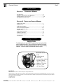
1
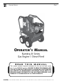
Operator’s Manual Page Operator’s Manual Ramteq JV Series Gas Engine / Diesel Fired READ THIS MANUAL This manual manual contains containsimportant importantinformation information for for the the use use and and safe operation safe operaof your of tion BEyour machine. RAMTEQ FAILURE machine. TO FAILURE READ THIS TOMANUAL READ THIS ANDMANUAL FOLLOWAND ITS INSTRUCTIONS FOLLOW ITS INSTRUCTIONS PRIOR TO OPERATING PRIOR TOOR OPERATING ATTEMPTING OR ANY ATTEMPTING SERVICE OR MAINTENANCE ANY SERVICE OR MAINTENANCE PROCEDURE COULD PROCEDURE RESULT IN COULD SERIOUS RESULT INJURY IN OR DEATHINJURY SERIOUS TO YOU OROR DEATH OTHER TOPERSONS; YOU OR OTHER ALSO DAMAGE PERSONS; TOALSO THE MACHINETO DAMAGE ORTHE TO OTHER MACHINE PROPERTY. OR TO OTHER PROPERTY. ® 30585 p r o g r e s14275 s i v e way aebsbtot r d B Road, C,v2t 6w3 TX pho n 604.850.6662 TO l l f 37421 r e e 800.663.8331 fax: 604.850.8886 9/07 AMAZING MACHINERY 2288 Gunbarrel e:Chattanooga, Phone: 1-800-504-7435 Fax: 1-800-504-7436 RAMTEQ n o r t hw f rsefeoway H oSuite u s to111-151 n, 77040 p h o n e: TENNESSEE 713.983.6000 fax: 713.983.6405 300-00010-01 300-00012-01 3/08 7/06 ® Operator’s Manual Page Table of Contents Section 1 Operator’s Manual Unpacking....................................................................2 Safety Instructions and Warnings.............................3 Maintenance Instructions...........................................4, 5 Operating Instructions...............................................6 Section 2 Parts and Service Manual Exploded View ............................................................7 Parts List....................................................................8 Burner Assembly.........................................................9 Control Box Assembly..............................................10 Hose, Wand, & Gun....................................................10 Pump List....................................................................11 Plumbing Diagram......................................................12 Wiring Diagram..........................................................13 Troubleshooting.........................................................14 Warranty...................................................................15 Unpacking Instructions INSPECTION Carefully unpack your new RAMTEQ equipment by removing the shrink wrap & banding from pallet. Remove the pressure washer from the pallet and check for any physical damage that may have occurred during shipment. Check for all parts specified and shown in figure 1. Included Parts • Pallet • Packing Material • Outer Box • Pressure Washer Machine • Operator’s Manual • Wand / Trigger Gun • Nozzles 0º, 15º, 25º, 40º • Hose 3/8” X 50’ • QC Hose Fittings NOTICE Information in this operator’s manual is subject to change without notice. RAMTEQ SHALL NOT BE LIABLE FOR TECHNICAL OR EDITORIAL ERRORS OR OMISSIONS CONTAINED HEREIN. This operator’s manual contains information protected by copyright. No part of this operator’s manual may be photocopied or reproduced in any form without prior written consent from RAMTEQ. © RAMTEQ, 2007 All rights reserved. 30585 p r o g r e s14275 s i v e way aebsbtot r d B Road, C,v2t 6w3 TX pho n 604.850.6662 TO l l f 37421 r e e 800.663.8331 fax: 604.850.8886 9/07 AMAZING MACHINERY 2288 Gunbarrel e:Chattanooga, Phone: 1-800-504-7435 Fax: 1-800-504-7436 RAMTEQ n o r t hw f rsefeoway H oSuite u s to111-151 n, 77040 p h o n e: TENNESSEE 713.983.6000 fax: 713.983.6405 300-00010-01 300-00012-01 3/08 7/06 ® Operator’s Manual Page Safety Guidelines � WARNING READ THIS FIRST! Failure to read and observe all WARNING statements could result in severe bodily injury or death, possible injury to other persons, damage to machine or other property. DO NOT operate this machine in areas where open flames are not permitted. DO NOT store or use combustible materials on or near this machine. Use this equipment only in well ventilated areas. Failure to follow this warning may cause carbon monoxide build up, fire or explosion, and possible injury or death. DO NOT fill gasoline tank while engine is running. Allow engine to cool before refueling. Should gasoline be spilled, move the machine away from the area of the spill. Do not attempt to restart the machine until the gasoline has fully evaporated. DO NOT operate engine if air cleaner or cover directly over the carburetor air intake is removed. DO NOT touch hot mufflers, cylinders or fins, as contact may cause burns DO NOT operate this machine while under the influence of alcohol, drugs or while fatigued. DO NOT direct discharge stream at yourself or others. Risk of injection or injury may occur. Never put your hand or fingers over the spray tip. Do not try to stop or deflect leaks with your hand or body. Always face nozzle and wand to the ground when testing. DO NOT operate this machine without wearing protective Eye Wear. Gloves, Hard Hat, Mask, Ear Plugs & Steel Toe Work Boots are also recommended, DO NOT wear loose clothing. Keep your body and clothing clear of the engine and discharge stream when the machine is running. DO NOT tie back or block trigger gun in OPEN position. Never leave the pressure washer unattended once you have started it. If you leave, shut down machine completely. DO NOT overreach or stand on an unstable support while operating this machine. Maintain good footing and balance. DO NOT permit this machine to run while unattended or for extended periods of time with trigger gun closed. Damage to pump may occur. DO NOT operate this machine in an unsafe manner or around unsupervised children. Keep all other personnel clear while operating this machine. This product should only be operated by trained personnel. DO NOT alter original factory settings prior to operating this machine. Risk of injury to yourself or other persons may occur. DO NOT remove hoses, guns, nozzles or any components while this machine is still hot or while it is running. DO NOT attempt to service this machine before reading the service manual. DO NOT use water with a temperature over 140 degrees Fahrenheit DO NOT put diesel fuel in to a gasoline tank or gasoline into a diesel tank. Observe correct markings on fuel tanks before filling. DO NOT operate this machine without knowing how to stop and bleed water pressures. Know all controls before using this machine. DO NOT spray caustic, acids or abrasive fluids through this machine. DO NOT permit water to freeze inside this machine. Pump and plumbing damage may occur. Use only recommended RAMTEQ parts when servicing this machine. RAMTEQ will not be held liable for any unauthorized modifications made to this machine. Any such action will void the warranty. When connecting battery, ensure that the RED battery cable is connected to the POSITIVE pole on the battery and the BLACK is connected to the NEGATIVE pole on the battery 30585 p r o g r e s14275 s i v e way aebsbtot r d B Road, C,v2t 6w3 TX pho n 604.850.6662 TO l l f 37421 r e e 800.663.8331 fax: 604.850.8886 9/07 AMAZING MACHINERY 2288 Gunbarrel e:Chattanooga, Phone: 1-800-504-7435 Fax: 1-800-504-7436 RAMTEQ n o r t hw f rsefeoway H oSuite u s to111-151 n, 77040 p h o n e: TENNESSEE 713.983.6000 fax: 713.983.6405 300-00010-01 300-00012-01 3/08 7/06 ® Operator’s Manual Page Maintenance Instructions MAINTENANCE PRECAUTIONS Do not permit acidic, caustic or abrasive fluids to be pumped through system. Periodically clean detergent inlet screen. This will ensure proper flow of water to the pump. High mineral content in water may adversely affect your machine and may require the use of a water softener to ensure proper operation. NEVER run the pump dry under any circumtances. Doing so will cause extreme damage to the pump. � WARNING FAILURE TO MAINTAIN HEAT EXCHANGER COIL MAY RESULT IN A STEAM EXPLOSION WHICH MAY CAUSE SERIOUS INJURY OR DEATH. HEAT EXCHANGER COIL MAINTENANCE Hard water conditions may eventually cause clogging in the heat exchanger coil if left unattended. Scale deposits will compromise the heating efficiency and produce an unsafe condition over time. It may be necessary to descale coil. Scale buildup from certain detergents may eventually clog up the heat exchanger coil causing an unsafe condition. Use only recommended detergents for better cleaning efficiency. Black carbon deposits that collect on the outside wall of the heat exchanger coil may be a result of using a poor grade of fuel or improper burner operation. Heating fuel should be void of water and sediments to eliminate the possibility of sooting and compromising the efficiency of the coil. MOVING, STORAGE Place machine in covered area when not in use to protect from elements. Protect machine from freezing in cold temperatures by storing in a heated location. ENGINE MAINTENANCE Refer to Engine Manual. WINTERIZING Non-float Tank Machines: To protect the machine from freezing temperatures while storing or transporting, connect short length of garden hose (approximately 3 ft.) to water inlet connection on machine. Remove the pressure nozzle from the wand and insert the short garden hose end into a container of antifreeze. Place the wand into the antifreeze container and start engine, running machine until antifreeze appears from the end of the wand. Turn engine “OFF” and replace pressure nozzle. Coil up hose and move machine to storage area. 30585 p r o g r e s14275 s i v e way aebsbtot r d B Road, C,v2t 6w3 TX pho n 604.850.6662 TO l l f 37421 r e e 800.663.8331 fax: 604.850.8886 9/07 AMAZING MACHINERY 2288 Gunbarrel e:Chattanooga, Phone: 1-800-504-7435 Fax: 1-800-504-7436 RAMTEQ n o r t hw f rsefeoway H oSuite u s to111-151 n, 77040 p h o n e: TENNESSEE 713.983.6000 fax: 713.983.6405 300-00010-01 300-00012-01 3/08 7/06 ® Operator’s Manual Page Maintenance Instructions ELECTRODE SETTINGS Inspection of all wires, spring contacts and electrodes should be done periodically. � WARNING IF BLACK OR WHITE SMOKE VENTS FROM EXHAUST PORT UPON STARTING EQUIPMENT, DISCONTINUE USE AND ADJUST AIR BANDS BEFORE RESTARTING. OIL BURNER AIR BAND ADJUSTMENT RAMTEQ sets oil burners at sea level. Air bands may need adjustment at higher elevations to offer enhanced performance of the burner and extended life of the machine. Adjustment of burner is done with pump motor and thermostat set to maximum. Loosen locking screw on air band, then close band until black smoke vents up exhaust vent. Take careful note of air band position when black smoke is first noticed. Slowly open air band until white smoke vents, then turn air band halfway back to where black smoke was first noted. Tighten air band locking screw. When properly set, the unit should NOT have either "black" smoke or "white" smoke during operation. PUMP MAINTENANCE Fill crankcase to dot on oil gauge window per specifications with the specific oil recommended by the pump manufacturer. Ensure the right oil for specific pump as it may vary. Change oil after 50 Hour Break-in Period. Change oil at every 500 Hour Intervals thereafter. UNLOADER ADJUSTMENT This RAMTEQ machine has the unloader correctly set at the the factory. Setting an unloader is a difficult job without the proper equipment and training. Should the need arise to change the unloader settings, please contact your local dealer. 30585 p r o g r e s14275 s i v e way aebsbtot r d B Road, C,v2t 6w3 TX pho n 604.850.6662 TO l l f 37421 r e e 800.663.8331 fax: 604.850.8886 9/07 AMAZING MACHINERY 2288 Gunbarrel e:Chattanooga, Phone: 1-800-504-7435 Fax: 1-800-504-7436 RAMTEQ n o r t hw f rsefeoway H oSuite u s to111-151 n, 77040 p h o n e: TENNESSEE 713.983.6000 fax: 713.983.6405 300-00010-01 300-00012-01 3/08 7/06 ® Operator’s Manual Page Operating Instructions LOCATION GUIDELINES Locate the machine on a solid and level surface so that engine and pump crankcase oil lubricate components properly. Avoid areas where water can build up in the working area. Possible injury may result. Locate the machine in a well-ventilated area and away from flammable materials or fumes. Be sure ventilation warnings are observed. Keep pressure washer at least 18” away from flammable materials. Locate the machine so the operator has easy access to the jetter/pressure washer and its controls. Locate the machine so that it is protected from external damage. To prevent damage and excessive hose wear, locate the unit so that the hose does not cross traffic areas. STARTING THE MACHINE Following the steps below will insure successful operation: Read this manual completely before attempting to start the machine. Check the fuel tank and fill with a good grade of gasoline (87 octane minimum) for gas engines and a high quality diesel fuel for diesel engines. Check the engine oil level and fill with appropriate oil. Check the pump oil level and fill with SAE 30w non-detergent oil if needed. Pull trigger on gun until a steady stream of water comes out the nozzle. This purges any air in the system. Slide fuel switch to the RIGHT and slide choke switch to the LEFT (closed position). Turn ON/OFF switch (on engine) to “ON”. Open water flow to reduce back pressure in pump. (Back pressure can overpower electric starter, preventing ignition.) Turn key to start gas engine and allow RPM to develop. Check for leaks in the system and cycle trigger gun to insure bypass is adjusted correctly. Repair any leaks and correct unloader adjustment if needed. Turn off machine before attempting any repairs. STOPPING THE MACHINE Turn engine to “OFF”. Pull gun trigger to release water pressure from system. Disconnect wand & gun assembly. Wind up pressure hose. CAUTION Always wear protective safety gear, such as, but not limited to, rain coat or coveralls, rubber boots, face shield or goggles, gloves and hearing protection. Do not run the machine for more than two minutes with water flow shut off (by-pass mode). This will over heat the jetter and could cause personal injury. Do not run hot water thru this pump. Hot water will damage the pump, and will void the warranty. 30585 p r o g r e s14275 s i v e way aebsbtot r d B Road, C,v2t 6w3 TX pho n 604.850.6662 TO l l f 37421 r e e 800.663.8331 fax: 604.850.8886 9/07 AMAZING MACHINERY 2288 Gunbarrel e:Chattanooga, Phone: 1-800-504-7435 Fax: 1-800-504-7436 RAMTEQ n o r t hw f rsefeoway H oSuite u s to111-151 n, 77040 p h o n e: TENNESSEE 713.983.6000 fax: 713.983.6405 300-00010-01 300-00012-01 3/08 7/06 ® Operator’s Manual Page Main Assy Exploded View See Pg 16 See Pg 16 See Pg 15 See Pg 13 See Pg 10 See Pg 9 30585 p r o g r e s14275 s i v e way aebsbtot r d B Road, C,v2t 6w3 TX pho n 604.850.6662 TO l l f 37421 r e e 800.663.8331 fax: 604.850.8886 9/07 AMAZING MACHINERY 2288 Gunbarrel e:Chattanooga, Phone: 1-800-504-7435 Fax: 1-800-504-7436 RAMTEQ n o r t hw f rsefeoway H oSuite u s to111-151 n, 77040 p h o n e: TENNESSEE 713.983.6000 fax: 713.983.6405 300-00010-01 300-00012-01 3/08 7/06 ® Operator’s Manual Page Main Assy Parts List See Pg 9 See Pg 10 See Pg 13 See Pg 15 See Pg 16 See Pg 16 See Pg 16 30585 p r o g r e s14275 s i v e way aebsbtot r d B Road, C,v2t 6w3 TX pho n 604.850.6662 TO l l f 37421 r e e 800.663.8331 fax: 604.850.8886 9/07 AMAZING MACHINERY 2288 Gunbarrel e:Chattanooga, Phone: 1-800-504-7435 Fax: 1-800-504-7436 RAMTEQ n o r t hw f rsefeoway H oSuite u s to111-151 n, 77040 p h o n e: TENNESSEE 713.983.6000 fax: 713.983.6405 300-00010-01 300-00012-01 3/08 7/06 ® Operator’s Manual Page Base Assy Parts List 30585 p r o g r e s14275 s i v e way aebsbtot r d B Road, C,v2t 6w3 TX pho n 604.850.6662 TO l l f 37421 r e e 800.663.8331 fax: 604.850.8886 9/07 AMAZING MACHINERY 2288 Gunbarrel e:Chattanooga, Phone: 1-800-504-7435 Fax: 1-800-504-7436 RAMTEQ n o r t hw f rsefeoway H oSuite u s to111-151 n, 77040 p h o n e: TENNESSEE 713.983.6000 fax: 713.983.6405 300-00010-01 300-00012-01 3/08 7/06 ® Operator’s Manual Page 10 Power Plate Assy Exploded View See Pg 12 Power Plate Assy Assembled View 30585 p r o g r e s14275 s i v e way aebsbtot r d B Road, C,v2t 6w3 TX pho n 604.850.6662 TO l l f 37421 r e e 800.663.8331 fax: 604.850.8886 9/07 AMAZING MACHINERY 2288 Gunbarrel e:Chattanooga, Phone: 1-800-504-7435 Fax: 1-800-504-7436 RAMTEQ n o r t hw f rsefeoway H oSuite u s to111-151 n, 77040 p h o n e: TENNESSEE 713.983.6000 fax: 713.983.6405 300-00010-01 300-00012-01 3/08 7/06 ® Operator’s Manual Page 11 Power Plate Assy Parts List 30585 p r o g r e s14275 s i v e way aebsbtot r d B Road, C,v2t 6w3 TX pho n 604.850.6662 TO l l f 37421 r e e 800.663.8331 fax: 604.850.8886 9/07 AMAZING MACHINERY 2288 Gunbarrel e:Chattanooga, Phone: 1-800-504-7435 Fax: 1-800-504-7436 RAMTEQ n o r t hw f rsefeoway H oSuite u s to111-151 n, 77040 p h o n e: TENNESSEE 713.983.6000 fax: 713.983.6405 300-00010-01 300-00012-01 3/08 7/06 ® Operator’s Manual Page 12 12v Burner Assembly 19 20 18 21 17 22 15 14 16 13 10 11 12 1 2 3 4 5 6 9 8 7 Beckett BE Ref.# Part # Part # 1 21699UF 254-00002-02 2 2140401 253-00004-01 3 21405 254-00001-11 4 31231U 259-00006-01 5 5874BKU 259-00007-01 6 5151501 259-00005-01 7 3494 259-00008-01 8 21807 252-00014-01 9 218440ZU 251-00002-03 10 21877U 252-00010-01 11 21754U 252-00007-01 12 3666 252-00013-01 13 3493 252-00012-01 14 5700 258-00006-01 15 7492 252-00009-01 16 51411 252-00011-01 17 51776U 252-00005-02 18 Specify 19 31802 256-00002-01 20 7435U 252-00005-01 21 51663 252-00006-01 22 245-00007-14 Description DC Motor Blower Wheel Coupling Air Guide Burner Housing - Black Air Band Air Shutter 8 Slot Cord Set Pump (CleanCut) Tube assembly 12 volt Coil Escutcheon plate spline nut Escutcheon plate Electrode kit Cad cell detector Ignitor gasketr kit Ignitor w/ICB Air tube assemblies Flange mounting gasket Ignitor only Ignitor Control Board Burner Nozzle, 1.75, 90A 30585 p r o g r e s14275 s i v e way aebsbtot r d B Road, C,v2t 6w3 TX pho n 604.850.6662 TO l l f 37421 r e e 800.663.8331 fax: 604.850.8886 9/07 AMAZING MACHINERY 2288 Gunbarrel e:Chattanooga, Phone: 1-800-504-7435 Fax: 1-800-504-7436 RAMTEQ n o r t hw f rsefeoway H oSuite u s to111-151 n, 77040 p h o n e: TENNESSEE 713.983.6000 fax: 713.983.6405 300-00010-01 300-00012-01 3/08 7/06 ® Operator’s Manual Page 13 Engine & Pump Assembly 30585 p r o g r e s14275 s i v e way aebsbtot r d B Road, C,v2t 6w3 TX pho n 604.850.6662 TO l l f 37421 r e e 800.663.8331 fax: 604.850.8886 9/07 AMAZING MACHINERY 2288 Gunbarrel e:Chattanooga, Phone: 1-800-504-7435 Fax: 1-800-504-7436 RAMTEQ n o r t hw f rsefeoway H oSuite u s to111-151 n, 77040 p h o n e: TENNESSEE 713.983.6000 fax: 713.983.6405 300-00010-01 300-00012-01 3/08 7/06 ® Operator’s Manual Page 14 Direct Drive Pump Comet Pump LWD3025G POS. ITEM 1 2 3 4 5 6 7 8 9 10 11 12 13 14 15 16 17 19 20 21 22 23 24 25 26 27 28 29 30 31 CODICE KIT DESCRIZIONE PART No. KIT DESCRIPTION 3218.0112.00 MANIFOLD Ø 15 mm 3202.0018.00 CAP G1/8 Q.tà Qty. 1 1 3609.0152.00 SCREW M6X55 1210.0046.00 A-D O-RING 2,62X 17,13 mm 3009.0087.00 A VALVE SEAT 3604.0017.00 A VALVE PLATE 1802.0177.00 A SPRING 1205.0025.00 A VALVE GUIDE 1210.0048.00 A-D O-RING 2,62X 20,24 mm 3202.0155.00 CAP 3609.0088.00 SCREW M5X10 1004.0012.00 CRANKCASE COVER 0402.0172.00 SPACER 1210.0386.00 D O-RING 3,53X44,04 mm 3019.0011.00 SNAP RING 8 6 6 6 6 6 6 6 3 1 1 1 1 0438.0069.00 BALL BEARING 20X52X15 mm 0403.0128.00 CRANKCASE 3200.0051.00 OIL DIPSTICK 0009.0196.00 B HEAD RING Ø15 mm 1241.0034.00 B PACKING Ø15 mm 1241.0030.00 B PACKING 15X22X5,5 mm 0009.0198.00 PACKING RETAINER Ø15 mm 1210.0223.00 B-D O-RING 1,78X26,7 mm 0019.0095.00 D OIL SEAL 15X24X5 mm 0 6 0 0 . 0 0 4 8 . 0 0 C NUT 2811.0080.00 C WASHER 8,2X14X1,5 mm 0202.0020.00 C PISTON Ø15 mm 2812.0038.00 C WASHER 1210.0055.00 C-D O-RING 1,78X 6,07 mm 2409.0044.00 PISTON GUIDES 1 1 1 3 3 3 3 3 3 3 3 3 3 3 3 MODELLI MODELS Pump Repair Kits Part # 221-00310-02 221-00302-01 221-00300-01 221-00315-03 Description Check Valve Kit Packing Kit Piston Kit Oil Seals POS. I 32 33 34 35 36 37 38 39 46 47 48 49 50 51 61 62 63 64 65 66 67 68 69 70 71 72 73 74 75 76 77 78 79 80 81 CODICE KIT 3011.0014.00 0205.0050.00 3019.0033.00 3201.0010.00 1210.0333.00 1210.0206.00 0402.0142.00 3609.0041.00 1210.0441.00 3200.0007.00 3200.0007.00 2811.0084.00 3202.0015.00 2811.0086.00 1220.0030.00 3410.0290.00 3410.0288.00 1210.0398.00 1210.0402.00 1802.0179.00 2409.0076.00 1210.0397.00 3410.0289.00 3410.0287.00 2409.0075.00 1210.0403.00 3009.0122.00 3002.0508.00 3009.0013.00 0009.0204.00 0009.0205.00 1210.0405.00 1210.0404.00 1210.0407.00 0204.0045.00 2409.0077.00 1210.0406.00 Qty. 1 1 1 3 D D D E E E-F E-F E E E-F E-F E-F E-F E-F E-F E-F E-F E-F E E-F E-F DESCRIZIONE Q.tà Qty. WRIST. PIN 3 CON. ROD 3 SNAP RING Ø18 mm 1 OIL INDICATOR 1 O-RING 1,78X23,52 mm 1 O-RING 2,62X101,27 mm 1 CRANKCASE COVER 1 SCREW M6X25 4 O-RING 2x14 mm 1 CAP 3/8GAS OT58 1 CAP 3/8GAS OT58 1 WASHER 16,7X22X1,5 mm 1 CAP G1/2 1 WASHER 21,2X27X1,5 mm 1 VALVE ASS. BLY. 6 INJECTOR BODY M22 x 1,5 1 INJECTOR BODY 3/8" NPT 1 O-RING 1 O-RING 1 SPRING 1 CHECK VALVE 1 O-RING 1 INJECTOR BODY KITM22 x 1,5 1 INJECTOR BODY KIT3/8" NPT 1 CHECK VALVE KIT 1 O-RING 1,78X8,73 mm VT 1 VALVE SEAT 1 HOUSING WITH BALL 1 SEAT KIT 1 RING 1 BACK RING 1 O-RING 1 O-RING 1 O-RING 1 HOUSING 1 PISTON ROD 1 O-RING 1 MODELLI MODELS Comet Part # 5025.0011.00 5019.0035.00 2409.0071.00 0019.0095.00 30585 p r o g r e s14275 s i v e way aebsbtot r d B Road, C,v2t 6w3 TX pho n 604.850.6662 TO l l f 37421 r e e 800.663.8331 fax: 604.850.8886 9/07 AMAZING MACHINERY 2288 Gunbarrel e:Chattanooga, Phone: 1-800-504-7435 Fax: 1-800-504-7436 RAMTEQ n o r t hw f rsefeoway H oSuite u s to111-151 n, 77040 p h o n e: TENNESSEE 713.983.6000 fax: 713.983.6405 300-00010-01 300-00012-01 3/08 7/06 ® Operator’s Manual Page 15 Coil, Shell & Plumbing Assy 30585 p r o g r e s14275 s i v e way aebsbtot r d B Road, C,v2t 6w3 TX pho n 604.850.6662 TO l l f 37421 r e e 800.663.8331 fax: 604.850.8886 9/07 AMAZING MACHINERY 2288 Gunbarrel e:Chattanooga, Phone: 1-800-504-7435 Fax: 1-800-504-7436 RAMTEQ n o r t hw f rsefeoway H oSuite u s to111-151 n, 77040 p h o n e: TENNESSEE 713.983.6000 fax: 713.983.6405 300-00010-01 300-00012-01 3/08 7/06 ® Operator’s Manual Page 16 Upper Frame Assy Dual Lance & Hose Assy's 30585 p r o g r e s14275 s i v e way aebsbtot r d B Road, C,v2t 6w3 TX pho n 604.850.6662 TO l l f 37421 r e e 800.663.8331 fax: 604.850.8886 9/07 AMAZING MACHINERY 2288 Gunbarrel e:Chattanooga, Phone: 1-800-504-7435 Fax: 1-800-504-7436 RAMTEQ n o r t hw f rsefeoway H oSuite u s to111-151 n, 77040 p h o n e: TENNESSEE 713.983.6000 fax: 713.983.6405 300-00010-01 300-00012-01 3/08 7/06 ® Operator’s Manual Page 17 Wiring Diagram BURNER (BECKETT) BLOWER MOTOR RED YEL RED PRIMARY CONTROL WHT WHT BLK YEL YEL YEL BLK RED BLK BLK CAD CELL IGNITOR PURPLE FUEL SOLENOID WHT BLK RED CONTROL PANEL AC BURNER SW + AC WHT RED BLK RED BLK BLK WHT 87 WHT WHT 1 86 P1 WHT 85 30 THERMOSTAT RED RED RED BRN Thermostat jumpers for troubleshooting FLOW SW or PRESSURE SW RED BLK STARTER SOLENOID BLK GRN WHT ALTERNATOR BATTERY GAS ENGINE 30585 p r o g r e s14275 s i v e way aebsbtot r d B Road, C,v2t 6w3 TX pho n 604.850.6662 TO l l f 37421 r e e 800.663.8331 fax: 604.850.8886 9/07 AMAZING MACHINERY 2288 Gunbarrel e:Chattanooga, Phone: 1-800-504-7435 Fax: 1-800-504-7436 RAMTEQ n o r t hw f rsefeoway H oSuite u s to111-151 n, 77040 p h o n e: TENNESSEE 713.983.6000 fax: 713.983.6405 300-00010-01 300-00012-01 3/08 7/06 ® Operator’s Manual Page 18 troubleshooting problem Low Water Pressure Insufficient water source Old or incorrect nozzle Plumbing or hose leak Obstruction in spray nozzle Unloader valve worn Pump valves dir ty or worn Check hose size/water source Replace nozzle Tighten, repair or replace leak Clean or replace nozzle Replace unloader Clean or replace packing/valves Detergent valve closed Low detergent level Chemical screen dir ty Open detergent valve Fill detergent container Clean detergent screen No fuel Burner switch turned off Thermostat set too low Clogged fuel filter Defective pressure switch Clogged burner nozzle Fuel pump malfunction Fill fuel tank with proper fuel Turn burner switch on Reset thermostat Replace fuel filter Replace pressure switch Replace burner nozzle Replace fuel pump Improper fuel being used Water contamination in fuel Improper air band adjustment Low fuel pressure Air leaks in fuel lines Soot on coils/burner assembly Dir ty burner nozzle Use Diesel #1/#2 or Kerosene Drain fuel and replace with new Readjust air band/altitude Adjust to specifications Check for air leaks or bubbles Clean coils/burner assembly Clean or replace burner nozzle Nozzle is dir ty Defective relief valve Unloader adjusted incorrectly Restriction on discharge hose Scale restricting flow in coil Clean or replace nozzle Replace relief valve Adjust unloader valve Remove nozzle and flush line Clean coil Burner Not Igniting Excessive Burner Smoke Relief Valve Leaks Engine Will Not Star t action No Chemical Flow Pressure cause Throttle lever off No fuel in engine Bad fuel or wrong fuel in engine Worn, foul, or dir ty spark plug(s) Pressure bulid up in pump Turn throttle lever to "on" position Fill fuel tank if needed Check to ensure correct fuel in tank Check spark plugs Squeeze trigger on gun Engine Runs Rough/No Power Low oil level Dir ty air filter Bad fuel or wrong fuel in engine Worn, foul, or dir ty spark plug(s) Overchoking Check oil level, fill if needed Check and replace air filter if needed Check to ensure correct fuel in tank Check spark plugs Open choke fully and crank engine Pump Noisy Air in suction line Pump valves dir ty Check valve springs worn Incoming water too hot Check inlet water fittings Clean/replace pump valves Replace check valves Reduce temperature/ambient Water In Oil High humidity environment Oil seal worn Plunger packing worn Change oil frequently Check and replace oil seal Check and replace packing Water Dripping/Pump Plunger packing is worn Plunger retainer oil ring worn Cracked ceramics Install new packing kit Replace oil ring Replace ceramics Fluctuating Pressure Valves worn Dir t or blockage in valves Pump sucking air Worn plunger packing Pump Head Overheating Extended period in bypass Replace with valve kit Clean or replace valve Check water/detergent supply Replace packing kit Pull trigger gun for water flow 30585 p r o g r e s14275 s i v e way aebsbtot r d B Road, C,v2t 6w3 TX pho n 604.850.6662 TO l l f 37421 r e e 800.663.8331 fax: 604.850.8886 9/07 AMAZING MACHINERY 2288 Gunbarrel e:Chattanooga, Phone: 1-800-504-7435 Fax: 1-800-504-7436 RAMTEQ n o r t hw f rsefeoway H oSuite u s to111-151 n, 77040 p h o n e: TENNESSEE 713.983.6000 fax: 713.983.6405 300-00010-01 300-00012-01 3/08 7/06 ® Operator’s Manual Page 19 WARRANTY MANUFACTURER LIMITED WARRANTY ENGINES Honda GX Series Engines; TWO years from date of purchase Honda will repair or replace any manufacturer defect at their expense. To be handled by Honda Service Centers. See owners Manual for details. PUMPS Pump manufacturers offer a "one and five" limited warranty on tri-plex ceramic plunger type pumps, from date of purchase. The body, head and power train of the pump is warranted for 5 years from date of purchase against manufacturer defects. See owners manual for details.The valves, packings and "o"rings are warranted for one year from date of purchase against manufacturer defects. See owner's manual for details. NOTE - Over Heated Pumps void all warranties. LIMITATION OF LIABILITY RAMTEQ and Equipment Manufacturer liability for special, incidental, or consequential damages is expressly disclaimed. In no event shall any liability exceed the purchase price of the product in question.The warranty contained herein is in lieu of all other warranties express or implied, including any implied warranty of fitness for particular purpose. NOTE - It is understood that a manufacturers limited warranty pertains to equipment used in it's prescribed manner, without abuse, and does not include wear and tear. NOTE - All freight charges incurred from manufacturer's warranty situations are the responsibility of the customer. Specifications, Warranties and Pricing are subject to change without notice. *Refund does not include shipping/handling fees. No refund will be given for installation kits. Customer is responsible for lost or misdirected packages. It is recommended that the customer insure the package for its full retail value. This warranty does not cover or include any damage as a result of acts of God, improper installation, alteration, negligence or abuse. 30585 p r o g r e s14275 s i v e way aebsbtot r d B Road, C,v2t 6w3 TX pho n 604.850.6662 TO l l f 37421 r e e 800.663.8331 fax: 604.850.8886 9/07 AMAZING MACHINERY 2288 Gunbarrel e:Chattanooga, Phone: 1-800-504-7435 Fax: 1-800-504-7436 RAMTEQ n o r t hw f rsefeoway H oSuite u s to111-151 n, 77040 p h o n e: TENNESSEE 713.983.6000 fax: 713.983.6405 300-00010-01 300-00012-01 3/08 7/06 ®