1
Installation manual
Tumble dryer
T5675
Type N2...
Installation manual in original language
438 9054-20/AU
2014.06.24
Additional safety instructions and warnings
3
Additional safety instructions and warnings
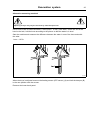
WARNING. Never stop a tumble dryer before the end of the drying cycle unless all items are
quickly removed and spread out so that the heat is dissipiated.
This appliance is not intended for use by young children or infirm persons unless they
have been adequately supervised by a responsible person to ensure that they can use
the appliance safely.
Young children should be supervised to ensure that they do not play with the appliance.
The tumble dryer is not to be used if industrial chemicals have been used for cleaning.
The lint trap has to be cleaned frequently, if applicable.
Lint must not to be allowed to accumulate around the tumble dryer (not applicable for
appliances intended to be vented to the exterior of the building).
The exhaust air must not be discharged into a flue which is used for exhausting fumes
from appliances burning gas or other fuels.
Fresh air ventilation openings shall not be blocked and/or sealed.
THIS APPLIANCE SHALL NOT BE USED TO DRY OFF SOLVENTS OR DRY-CLEANING
FLUIDS.
DO NOT USE OR STORE FLAMMABLE MATERIALS IN THE APPLIANCE STORAGE DRAWER
OR NEAR THIS APPLIANCE.
DO NOT SPRAY AEROSOLS IN THE VICINITY OF THIS APPLIANCE WHILE IT IS IN
OPERATION.
For parts, service and technical assistance please contact:
Electrolux Laundry Systems
5–7 Keith Champbell Crt Scoresby Victoria 3179
4
Additional safety instructions and warnings
To minimize the risk of fire in a tumble dryer, the following should be observed:
• Items that have been spotted or soaked with vegetable or cooking oil constitute a fire
hazard and should not be placed in a tumble dryer.
• Oil-affected items can ignite spontaneously, especially when exposed to heat sources
such as in a tumble dryer. The items become warm, causing an oxidation reaction in the
oil. Oxidation creates heat. If the heat cannot escape, the items can become hot enough
to catch fire. Piling, stacking or storing oilaffected items can prevent heat from escaping
and so create a fire hazard. If it is unavoidable that fabrics that contain vegetable or
cooking oil or have been contaminated by hair care products be placed in a tumble
dryer they should first be washed in hot water with extra detergent - this will reduce,
but not eliminate, the hazard. The ’cool down’ cycle of tumble dryers should be used
to reduce the temperature of the items. They should not be removed from the tumble
dryer or piled or stacked while hot.
• Items that have been previously cleaned in, washed in, soaked in or spotted with
petrol/gasoline, dry-cleaning solvents or other flammable or explosive substances
should not be placed in a tumble dryer. Highly flammable substances commonly used in
domestic environments include acetone, denatured alcohol, petrol/gasoline, kerosene,
spot removers (some brands), turpentine, waxes and wax removers.
• Items containing foam rubber (also known as latex foam) or similarly textured rubber. like
materials should not be dried in a tumble dryer on a heat setting. Foam rubber materials
can, when heated, produce fire by spontaneous combustion.
• Fabric softeners or similar products should not be used in a tumble dryer to eliminate
the effects of static electricity unless this practice is specifically recommended by the
manufacturer of the fabric softener or product.
• Undergarments that contain metal reinforcements should not be placed in a tumble dryer.
Damage to the tumble dryer can result if metal reinforcements come loose during drying.
When available a drying rack could be used for such items.
• Plastic articles such as shower caps or babies’ waterproof napkin covers should not be
placed in a tumble dryer.
• Rubber-backed articles, clothes fitted with foam rubber pads, pillows, galoshes and
rubber-coated tennis shoes should not be placed in a tumble dryer.
Contents
Contents
1 Safety Precautions ............................................................................................................. 7
1.1 Symbols...................................................................................................................... 8
2 Technical data .................................................................................................................... 9
2.1 Drawing ...................................................................................................................... 9
2.2 Technical data............................................................................................................. 10
2.3 Connections................................................................................................................ 10
2.4 Sound levels ............................................................................................................... 10
3 Setup.................................................................................................................................. 11
3.1 Unpacking................................................................................................................... 11
3.2 Siting........................................................................................................................... 12
3.3 Mechanical installation ............................................................................................... 12
4 Marine installation .............................................................................................................. 13
5 Reversing the door............................................................................................................. 14
6 Evacuation system ............................................................................................................. 18
6.1 Air principle................................................................................................................. 18
6.2 Fresh air ..................................................................................................................... 19
6.3 Exhaust duct............................................................................................................... 20
6.4 Shared exhaust duct................................................................................................... 21
6.5 Exhaust dimensioning ................................................................................................ 22
6.6 Adjusting the dryer...................................................................................................... 23
7 Steam connection .............................................................................................................. 26
7.1 Connecting the steam................................................................................................. 26
7.2 Steam calorifier........................................................................................................... 27
8 Gas connection .................................................................................................................. 29
8.1 General....................................................................................................................... 29
8.2 Table of pressure and adjustment .............................................................................. 30
8.3 Test run....................................................................................................................... 31
8.4 Converting instructions ............................................................................................... 32
8.5 Data label ................................................................................................................... 34
9 Electrical connection .......................................................................................................... 35
9.1 Electrical installation ................................................................................................... 35
9.2 Single-phase connection ............................................................................................ 36
9.3 Three-phase connection............................................................................................. 37
9.4 Electrical connections................................................................................................. 38
9.5 Functions for I/O-cards ............................................................................................... 39
9.5.1 Central payment (2J) .......................................................................................... 39
9.5.2 Central payment (2J) .......................................................................................... 40
9.5.3 External coin meter/Central payment (2K).......................................................... 41
9.5.4 Price reduction (2K) ............................................................................................ 42
9.6 Option ......................................................................................................................... 43
9.6.1 External connection 100 mA ............................................................................... 43
10 Function check ................................................................................................................. 44
The manufacturer reserves the right to make changes to design and component specifications.
Safety Precautions
1 Safety Precautions
This appliance can be used by children aged from 8 years and above and persons with reduced physical,
sensory or mental capabilities or lack of experience and knowledge if they have been given supervision or
instruction concerning use of the appliance in a safe way and understand the hazards involved. Children
shall not play with the appliance. Cleaning and user maintenance shall not be made by children without
supervision.
Children of less than 3 years should be kept away unless continuously supervised.
The machine is not to be used if industrial chemicals have been used for cleaning.
Do not dry unwashed items in the machine.
Items that have been soiled with substances such as cooking oil, acetone, alcohol, petrol, kerosene, spot
removers, turpentine, waxes and wax removers should be washed in hot water with an extra amount
of detergent before being dried in the machine.
Items such as foam rubber (latex foam), shower caps, waterproof textiles, rubber backed articles and
clothes or pillows fitted with foam rubber pads should not be dried in the machine.
Fabric softeners or similar products should be used as specified by the fabric softener instructions.
The final part of a drying cycle occurs without heat (cool down cycle) to ensure that the items are left at a
temperature that ensures that the items will not be damaged.
Remove all objects from pockets such as lighters and matches.
WARNING. Never stop the machine before the end of the drying cycle unless all items are quickly removed
and spread out so that the heat is dissipated.
Adequate ventilation has to be provided to avoid the back flow of gases into the room for appliances
burning other fuels, including open fires.
Exhaust air must not be discharged into a flue which is used for exhausting fumes from appliances burning
gas or other fuels.
The machine must not be installed behind a lockable door, a sliding door or a door with a hinge on the
opposite side to that of the machine.
If the machine has a lint trap this has to be cleaned frequently.
The lint must not be accumulated around the machine.
DO NOT MODIFY THIS APPLIANCE.
All external equipment which is connected to the machine must be CE/EMC-approved and connected using
an approved shielded cable.
All external equipment must be connected according to the instructions in the installation manual.
In order to prevent damage to the electronics (and other parts) that may occur as the result of condensation,
the machine should be placed in room temperature for 24 hours before being used for the first time.
Servicing shall be carried out only by authorized personnel.
Only authorized spare parts shall be used.
When performing service or replacing parts, the power must be disconnected.
7
Safety Precautions
8
Gas heated tumble dryer:
Before installation, check that the local distribution conditions, nature of gas and pressure and the
adjustment of the appliance are compatible.
The machine is not to be installed in rooms containing cleaning machines with perchloroethylene,
TRICHLOROETHYLENE or CHLOROFLUOROCONTAINING HYDROCARBONS as cleaning agents.
If you can smell gas:
• Do not switch on any equipment
• Do not use electrical switches
• Do not use telephones in the building
• Evacuate the room, building or area
• Contact the person responsible for the machine
1.1 Symbols
Caution
Caution, hot surface
Read the instructions before using the machine
Technical data
9
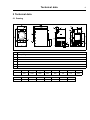
2 Technical data
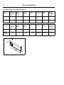
2.1 Drawing
B(b)
B(a)
A
1
H
K
L
4
3
3
7
7
N
C
J
G
2
6
6
D E
5
5
I
F
1
Operating panel
2
Door opening, ⌀ 810 mm
3
Electrical connection
4
Gas connection
5
Exhaust connection
6
Steam: in
7
Steam: out
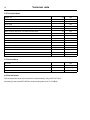
mm
mm
A
B(a)
B(b)
C
D
E
F
G
961
1560
1640
1857
660
720
170
1490
H
I
J
K
L
M
N
200
180
1560
50
480
580
805
M
10
Technical data
2.2 Technical data
Weight, net
kg
283
litres
675
Drum diameter
mm
913
Drum depth
mm
990
Drum speed, medium load
rpm
40
Drum volume
Rated capacity, filling factor 1:18 (Max. load)
kg
37.5
Rated capacity, filling factor 1:22 (Recommended load)
kg
30.6
kW
32
kW
40
Heating: Gas
kW
42
Heating: Steam
kW
46
Heating: Electricity
Maximum air flow, Electric 50 Hz / 60 Hz
m3/h
1140 / 1140
Maximum air flow, Gas 50 Hz / 60 Hz
m3/h
1140 / 1140
Maximum air flow, Steam 50 Hz / 60 Hz
m3/h
1380 / 1380
Maximum static back pressure, Electric 50 Hz / 60 Hz
Pa
270 / 800
Maximum static back pressure, Gas 50 Hz / 60 Hz
Pa
410 / 800
Maximum static back pressure, Steam 50 Hz / 60 Hz
Pa
900 / 1100
2.3 Connections
Air outlet
⌀ mm
1”
ISO 7/1–Rp1/2
-
ISO 7/1–Rp1/2
1/2”
ISO 7/1–R1/2
Steam outlet
Condensate outlet
Gas connection
2.4 Sound levels
The sound power level of the machine is determined by using ISO 3747:2012.
According to test code IEC 60704-2-4 the sound power level is 70 dB(A).
200
Setup
11
3 Setup
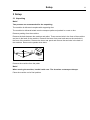
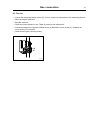
3.1 Unpacking
Note!
Two persons are recommended for the unpacking.
The machine is delivered complete with supporting feet.
The machine is delivered bolted onto the transport pallet and packed in a crate or box.
Remove packing from the machine.
Remove the bolts between the machine and pallet. There are two bolts in the front of the machine
and two in the back of the machine. Remove the lower front panel and remove the two bolts in
the front of the machine. Remove the lower rear panel and remove the two bolts in the back of
the machine. Remount the panels when done.
①
fig.7189A
Remove the machine from the pallet.
Note!
When moving the machine, handle it with care. The drum has no transport clamps.
Place the machine on its final position.
Setup
12
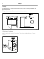
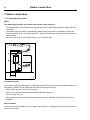
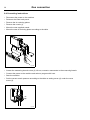
3.2 Siting
The machine should be positioned so that there is plenty of room for working, both for the user
and service personnel.
The figure shows minimum distance to a wall and/or other machines.
②
Max. 50 mm /
1 15/16 inch
500 mm /
20 inch
10 mm /
3/8 inch
10 mm /
3/8 inch
Min.150 mm / 5 7/8 inch
Min. 20 mm /
13/16 inch
fig.7187
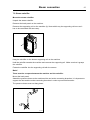
3.3 Mechanical installation
Level the machine with the feet of the machine. The maximum height adjustment of the feet
is 15 mm.
③
fig.7188
Marine installation
13
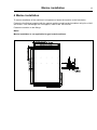
4 Marine installation
To ensure steadiness of the machine it is important to fasten the machine to the foundation.
Fasten the four fittings (supplied with the marine machine model) to the foundation using four x M10
set screws. If the four fittings are not supplied, order kit No. 487193544.
Fasten the machine to the fittings.
Note!
Marine installation is not applicable for gas heated machines.
④
73 mm / 2 7/8 inch
43.3 mm / 1 11/16 inch
1419.1 mm / 55 7/8 inch
1359.6 mm / 53 9/16 inch
15.3 mm / 9/16 inch
925.5 mm / 36 7/16 inch
866 mm / 34 1/8 inch
45 mm / 1 3/4 inch
M10
14
Reversing the door
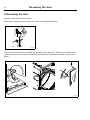
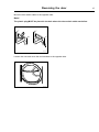
5 Reversing the door
Disconnect the power to the machine.
Demount the hinges and remove the door. Remove the upper hinge first.
⑤
fig.7166
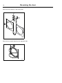
Remove the screws on the front panel and carefully loosen the panel. Push the door switch cable
down through the hole in order to access the cable and then disconnect the cable. Remove the
panel.
⑥
fig.7548
Reversing the door
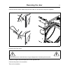
Move the door switch cable to the opposite side.
Note!
The plastic plug MUST be placed in the hole where the door switch cable was before.
⑦
fig.7170
Loosen the nuts and move the two brackets to the opposite side.
⑧
fig.7171
15
Reversing the door
16
Move the door switch on the front panel.
⑨
2
3
1
4
fig.7172
Move the four metal clips from the opposite side.
⑩
fig.7174
Reversing the door
17
Connect the door switch cable and push the cable in over the drum and pull it upwards.
⑪
fig.7549
Remount the front panel.
Ensure that the door switch cable does not get damaged when remounting the front panel.
Fasten the hinges and mount the door on the opposite side.
Connect the power to the machine.
Test run the machine.
Evacuation system
18
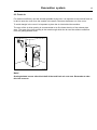
6 Evacuation system
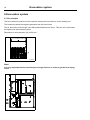
6.1 Air principle
The fan creates low pressure in the machine, drawing air into the drum via the heating unit.
The heated air passes through the garments and the drum holes.
The air then flows outh through a lint filter positioned below the drum. Then the air is evacuated
through the fan and exhaust system.
Dimension for air evacuation (A) is 200 mm.
⑫
A
fig.W00264
Note!
It is very important that the machine gets enough fresh air in order to get the best drying
result.
⑬
Evacuation system
19
6.2 Fresh air
For maximum efficiency and the shortest possible drying time, it is important to ensure that fresh air
is able to enter the room from the outside in the same volume as that blown out of the room.
To avoid draught in the room it is important to place the air inlet behind the machine.
The area of the air inlet opening is recommended to be five times the size of the exhaust pipe
area. The area of the inlet opening is the area through which the air can flow without resistance
from the grating/slatted cover.
⑭
A
5x A
fig.7183
Note!
Gratings/slatted covers often block half of the total fresh air vent area. Remember to take
this into account.
20
Evacuation system
6.3 Exhaust duct
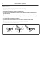
• Only rigid or flexible metal duct should be used for exhausting.
• Plastic ducting is not to be used.
• Recommended material for exhaust is galvanized steel.
• The duct is not to be assembled with screws of other fastening means that extend into the
duct and catch lint.
• The exhaust air should not be vented into a wall, a ceiling, or a concealed space of building.
• The exhaust duct must lead clear of the building as condensation may cause frost damage
to the building.
• The exhaust duct must lead to the outdoors.
• The exhaust duct must be placed in such a way that it is protected on the outside.
• The exhaust duct must be smooth on the inside (low air resistance).
• The exhaust duct must have gentle bends.
⑮
Evacuation system
21
6.4 Shared exhaust duct
It is recommended that each machine is connected to a separate exhaust duct.
When several machines shall use the same exhaust duct the exhaust duct must increase after
each machine.
⑯
1
2
3
4
5
6
7
8
9
10
Exhaust duct ⌀ mm
200
370
440
500
560
630
670
700
770
830
Minimum area of fresh-air intake
m2
0.2
0.5
0.8
1.0
1.2
1.6
1.8
1.9
2.3
2.7
Number of machines
The exhaust duct diameter must not be reduced.
22
Evacuation system
6.5 Exhaust dimensioning
It is important that the machine has correct air volume compared to each machines power.
If the air flow is smaller or larger this will result in a longer drying period.
The machine is designed to work with the maximum static back pressure according to the table in
the technical data section.
The exhaust duct must be designed so the static back pressure measured 1 m from the exhaust
outlet does not exceed the maximum allowable back pressure specified in Technical data.
If the outlet pipe is longer or the ventilation is not properly designed we recommend to clean the
outlet pipes periodically.
All cover panels must be mounted in order for the machine to work in the best way.
Evacuation system
23
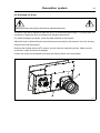
6.6 Adjusting the dryer
Adjusting the dryer may only be carried out by authorized personnel.
The dryer is pre-set for optimal air flow with up to 15 m equivalent pipe length. For longer pipes it is
necessary to adjust the dryer according to the following instructions.
For default settings from factory, check the label attached on the damper.
Adjust the dryer by demounting the lower back panel and measure the pressure in the fan housing.
Demount the lower back panel.
Demount the heating sensor (NTC sensor) (A) and insert the measuring device. Make sure the
connection is tight to prevent air leakage.
Loosen the screws on the damper and open the damper (B) as much as possible.
⑰
B
A
fig.7524
Evacuation system
24
Measure with a pressure measuring instrument (manometer) with an empty drum and with a
program without heat.
By opening and closing the damper (B) the pressure at the heating sensor (NTC sensor) (A)
is either lowered or raised.
The optimum drying performances are achieved when the measured static pressure correspond to
the value listed in the following table.
Model name
Heating / Frequency
Static pressure
in NTC sensor
position (Pa)
Resulting Nominal air flow cold
empty machine (m3/h)
T5675
Electric / 50 Hz
500
1140
T5675
Electric / 60 Hz
1150
1140
T5675
Gas / 50 Hz
750
1140
T5675
Gas / 60 Hz
1150
1140
T5675
Steam / 50 Hz
900
1380
T5675
Steam / 60 Hz
1100
1380
Evacuation system
25
Alternative measuring meathod
Adjusting the dryer may only be carried out by authorized personnel.
Use a home made U tube manometer, a hose (max ⌀ 10 mm), with water. Insert one end of the
hose in the hole, hold the hose according to the picture so that the water is in level.
Start the machine and measure the difference between the water in one of the hose ends with
the other.
1 mm = 10 Pa.
⑱
X mm
fig.7528
When the dryer is adjusted remount the heating sensor (NTC sensor) (A) and lock the damper (B)
in the new position with the screws.
Remount the lower back panel.
Steam connection
26
7 Steam connection
7.1 Connecting the steam
Note!
The steam pipe must be cut off and must not be under pressure.
• The branch pipe’s must be located at the top of the main steam pipe to prevent condensation in
the steam.
• The branch pipe must have a descending gradient and must end at a height above the inlet
connecting branch (5). For measurements L, M and N, please refer to the dimension drawing in
Tehnical data.
• Mount a plug valve (a) and a dirt collector (c) in the brach pipe.
⑲
a
b
5
N
6
b
c
a
M
L
fig.7194
Condensate return
It is important that the brach pipe for condensed water on return to the main condensate pipe has a
descending gradient and is lower than the outlet connecting branch (6).
• Mount a dirt collector (b) in the return pipe.
• Mount a mechanical water discharger behind the dirt collector (c).
• Mount a plug valve (a).
• Mount pressure hoses between the branch pipes and the machine. Note that hoses are not
supplied.
Pipe insulation
All pipes must be insulated in order to reduce risk of burning. Insulation also reduces loss of heat
to the surroundings.
Steam connection
27
7.2 Steam calorifier
Mount the steam calorifier
Unpack the steam calorifier.
Demount the back panel on the machine.
Demount the supporting rail on the machine (A). Note which way the supporting rail turns as it
has to be remounted the same way.
⑳
A
Hang the calorifier on the bottom supporting rail on the machine.
Hold the calorifier towards the machine and remount the supporting rail. Make sure that it grasps
the calorifier.
Fasten the calorifier into the supporting rail with the screws.
Note!
There must be no space between the machine and the calorifier.
Mount the back panel.
Attatch the pressure hoses to the machines inlet and outlet connecting branches. It is important to
support the inlet and the outlet connecting branches in order to prevent deformation.
The pressure hoses must not hang down.
21
fig.7195
28
When ready
• Leak test the system.
• Clean the dirt collectors.
• Perform a function chek.
Steam connection
Gas connection
29
8 Gas connection
8.1 General
Caution
This appliance shall be installed only by authorised personnel and in accordance with the manufacturer’s
installation instructions, local gas fitting regulations, municipal building codes, electrical wiring regulations,
AS5601/AG601 — Gas Installations and any other statutory regulations.
Mount a shut-off valve upstream from the machine.
The gas connection to the machine should be dimensioned to an output depending upon the
kW-rating of the machine.
The factory nozzle pressure setting must correspond to the fuel value given on the data label.
Check that the nozzle pressure and fuel value correspond with the values in the gas tables on the
following pages. If not, contact the supplier.
Bleed the pipe system before connecting the machine. Refer to AS5601 for correct gas pipe size.
After connection, test all joints for leaks.
Gas connection
30
8.2 Table of pressure and adjustment
Gas
category
Natural
Total nominal gas consumption
(MJ/h)
151
Inlet
pressure
(kPa)
Injector
pressure
(kPa)
1.13
0.80
Injector size
(⌀ mm)
Air reducing
plate (mm)
Label
number
May be
available
in following
countries
4.00
490359201
Default
AU
490375821
AU
A = 18
Propane
151
2.75
2.61
2.40
490359201
A = 18
Gas
category
Natural
Total nominal gas consumption
(MJ/h)
151
Inlet
pressure
(kPa)
Injector
pressure
(kPa)
1.13
0.80
Injector size
(⌀ mm)
Air reducing
plate (mm)
Label
number
May be
available
in following
countries
4.00
490359201
490375822
NZ
490375823
NZ
A = 18
General
product LPG
151
2.75
2.61
2.30
490359201
A = 18
22
A
Gas connection
31
8.3 Test run
• Loosen the measuring branch screw (2) 1/4 turn; connect a manometer to the measuring branch.
• Select a program with heat.
• Start the machine.
• Check the nozzle pressure, see “Table of pressure and adjustment”.
• If necessary adjust the regulator setting screw (4) behind the cover screw (3). Replace the
cover screw (3) if removed.
• Check that the gas is burning evenly.
23
2
3, 4
fig.7120
Gas connection
32
8.4 Converting instructions
• Disconnect the power to the machine.
• Demount the lower back panel.
• Remove the air reducing plates.
• Remove the nozzle (1).
• Mount the new supplied nozzle.
• Mount the new air reducing plates according to the table.
24
1
fig.7182
• Loosen the measuring branch screw (2) 1/4 turn; connect a manometer to the measuring branch.
• Connect the power to the machine and select a program with heat.
• Start the machine.
• Set the correct nozzle pressure according to the table on setting screw (4) under the cover
screw (3).
25
2
3, 4
fig.7120
Gas connection
• Check that the gas flame burns evenly.
• Mount the cover screw (3).
• Remount the lower back panel.
33
Gas connection
34
8.5 Data label
When the machine is to be converted to another gas type, the data label at the rear of the machine
must be updated in order for the data to be correct.
Place the data label enclosed in the conversion kit on top of the data label as shown below. If there
are more than one data label, select the label with the correct country code and gas type.
26
Product no.:
Serial no.:
OC:
Program:
Typ e :
WXXXXX
9868XXXXXX
09XXX / 99XXXXX
09XXXXXX
10XX
432XXXXXX,5XXX
432XXXXXXXX
WN3...WN3XXXX
Vo lta g e :
WXXXXX
9868XXXXXX
09XXX / 99XXXXX
Date(YYMM): 10XX
09XXXXXX
X kg
WN3...WN3XXXX
380 400V
3N
50Hz
Rated Input:
1,6kW
Product no.:
Serial no.:
OC number:
Capacity:
Typ e /Mo d e l:
~
GAS : PROP ANE
INPUT : A MJ /H
MANIF. PRESSURE : 2.75 KP A
ORF. M. BURNER MM. : Ø D MM
AGA AP P ROVAL NO : B
Art. No. ..........
10A
GAS : NA TURAL
INPUT : 1 19 MJ/H
MANIF. PRESSURE : 0.8 KP A
ORF. M. BURNER MM. : Ø 3.50 MM
AGA AP P ROVAL NO : ?
Electrolux Laundry Systems
5-7 Keith Campbell Crt Scoresby V
ictoria 3179
For safety reasons use only genuine spar
e par ts.
Mad e in S we d e n
Ele ctrolux La undry S ys te ms AB
341 80 Ljungby, S we de n.
Product no.:
Serial no.:
OC:
Program:
Typ e :
WXXXXX
9868XXXXXX
09XXX / 99XXXXX
09XXXXXX
10XX
432XXXXXX,5XXX
432XXXXXXXX
WN3...WN3XXXX
fig.7110A
Electrical connection
35
9 Electrical connection
9.1 Electrical installation
The electrical installation may only be carried out by qualified personnel.
Machines with frequency-controlled motors can be incompatible with certain types of earth leakage circuit
breaker. It is important to know that the machines are designed to provide a high level of personal safety,
which is why items of external equipment such as earth leakage circuit breakers are not necessary. If you
still want to connect your machine across an earth leakage circuit breaker, please remember the following:
• contact a skilled, authorised installation company to ensure that the appropriate type of breaker is chosen
and that the dimensioning is correct
• for maximum reliability, connect only one machine per earth leakage circuit breaker
• it is important that the earth wire is properly connected.
In instances where the machine is not equipped with an omni-polar switch, one must be installed
beforehand.
In accordance with the wiring rules: mount a multi-pole switch prior to the machine to facilitate
installation and service operations.
The connecting cable should hang in a gentle curve.
Fuse size, see table.
Electrical connection
36
9.2 Single-phase connection
Demount the cover panel from the supply unit. Connect the earth and other wires as shown.
1NAC
1AC
1AC
L1
L2/N
When the installation is completed remount the cover panel and check:
• That the drum is empty.
• That the machine operates by connecting the power to the machine and start a program with heat.
Electrical connection
37
9.3 Three-phase connection
Demount the cover panel from the supply unit. Connect the earth and other wires as shown.
3AC
3AC
L1
L2
L3
L1
L2
L3
3NAC
3NAC
N
When the installation is completed remount the cover panel and check:
• That the drum is empty.
• That the machine operates by connecting the power to the machine and start a program with heat.
Electrical connection
38
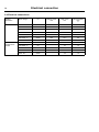
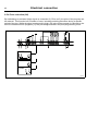
9.4 Electrical connections
Heating
alternative
Main voltage
Electric heated
Gas
heated/Steam
heated
Hz
Heating power
kW
Total power
kW
Recommended
fuse
A
380–415V 3/3N ~
50/60
32.0
34.6
50
380–415V 3/3N ~
50/60
40.0
42.6
63
440–480V 3 ~
60
32.0
34.7
50
440–480V 3 ~
60
40.0
42.7
63
230–240V 3 ~
50/60
32.0
34.4
100
230–240V 3 ~
50/60
40.0
42.4
125
200V 3N ~
50/60
32.0
34.2
100
380–415V 3/3N ~
50/60
-
2.6
10
440–480V 3 ~
60
-
2.7
10
230–240V 3 ~
50/60
-
2.4
10
230–240V 1 ~
50/60
-
2.2
10
50/60
-
2.2
10
200V 3N ~
Electrical connection
39
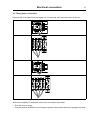
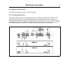
9.5 Functions for I/O-cards
The electrical schematic can be one of the following:
9.5.1 Central payment (2J)
To start the machine from a central payment system, the payment system must transmit a start
pulse 300–3000 ms (500 ms is recommended) with a minimum pause of 300 ms (500 ms is
recommended) between two pulses. The start pulse can be either 230V or 24V. In order to receive
a feedback signal once the machine has started, 230V or 24V must be connected to connection 19.
The feedback signal on connection 18 remains active (high) during the entire program.
27
fig.7440
40
Electrical connection
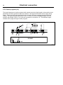
9.5.2 Central payment (2J)
The central payment or booking system shall transmit an active (high) signal to the machine once
permission has been granted to start the machine. The signal must remain active (high) during
drying. When the signal gets inactive (low) the machine will abort ongoing program and enter
cooling. The signal can be either 230V or 24V. In order to receive a feedback signal once the
machine has started, 230V or 24V must be connected to connection 19. The feedback signal
remains active (high) during the entire program.
P rogra m run
28
fig.7439
Electrical connection
41
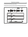
9.5.3 External coin meter/Central payment (2K)
The signal received from external coin meters must be a pulse between 300–3000 ms (500 ms is
recommended) with a minimum pause of 300 ms (500 ms is recommended) between two pulses.
29
fig.7438
42
Electrical connection
9.5.4 Price reduction (2K)
By maintaining an activated (high) signal on connection 5 ("Price red"), the price of the program can
be reduced. This function has a number of uses, including providing reductions during a specific
period of the day. Whilst the signal remains active (high), the price of the program is reduced (or the
time is increased on time programs), by the percentage entered in the price programming menu.
30
fig.7441
Electrical connection
43
9.6 Option
9.6.1 External connection 100 mA
A special connection terminal is located on the connection console.
This connection can be used as external control of a fan.
The terminal for external control is equipped with 220–240V max.100 mA and is intended solely for
the operation of a contactor.
Max. connection 100 mA.
Gnd. must not be used for earthing of external board.
31
X1
X2 Gnd.
fig.7154
Function check
44
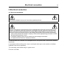
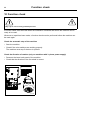
10 Function check
May only be carried out by qualified personnel.
A function check must be made when the installation is finished and before the machine can be
ready to be used.
Whenever a repair has been made, a function check must be performed before the machine can
be used again.
Check the automatic stop of the machine
• Start the machine.
• Check if the micro switches are working properly:
The machine must stop if the door is opened.
Check the direction of rotation (only on machines with 3–phase power supply)
• Demount the lower back panel of the machine.
• Check that the direction of the fan wheel is correct.
32
fig.7118A
Function check
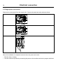
45
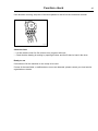
If the direction is wrong, swop two of the three phases to the left on the connection terminal.
33
fig.7119
Check the heat
• Let the machine work for five minutes on a program with heat.
• Check that the heating is working by opening the door and feel if there is heat in the drum.
Ready to use
If all tests are OK the machine is now ready to be used.
If some of the tests failed, or deficiencies or errors are detected, please contact your local service
organisation or dealer.
lastpage
Electrolux Laundry Systems Sweden AB
341 80 Ljungby, Sweden
www.electrolux.com/laundrysystems
Share more of our thinking at www.electrolux.com