1
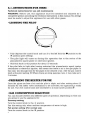
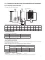
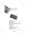
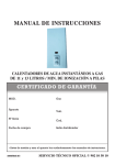
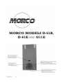
MORCO MODELS D-61B,
D-61E AND G11E
10005246
00
INDEX
A.- ENGLISH
A.1. INSTRUCTIONS FOR USERS ..........................................................................
A.2. TECHNICAL INSTRUCTIONS FOR INSTALLATION ENGINEERS .............
A.2.1. TECHNICAL INFORMATION.................................................................
A.2.2. INSTALLATION INSTRUCTIONS...........................................................
A.2.3. LOOKING AFTER THE APPLIANCE......................................................
A.2.4. SYMBOLS .................................................................................................
A.2.5. WARRANTY..............................................................................................
4
7
7
11
15
16
16
B.- FRANÇAIS
B.1. INSTRUCTIONS POUR L’UTILISATEUR..........................................................
B.2. INSTRUCTIONS TECHNIQUES POUR L’INSTALLATEURS ..........................
B.2.1. DONNÉS TECHNIQUES .........................................................................
B.2.2. NORMES D’INSTALLATION ...................................................................
B.2.3. INSTRUCTIONS POUR LA MISE EN MARCHE ....................................
B.2.4. MAINTENANCE.......................................................................................
B.2.5. SYMBOLES ...............................................................................................
B.2.6. GARANTIE................................................................................................
18
21
21
25
30
32
33
34
C.- NEDERLANS
C.1. GEBRUIKSAANWIJZING..................................................................................
C.2. TECHNISCHE INSTRUCTIES VOOR INSTALLATIE MONTEURS...............
C.2.1. TECHNISCHE INFORMATIE..................................................................
C.2.2. INSTRUCTIES VOOR DE INSTALLATIE................................................
C.2.3. INSTRUCTIES VOOR HET BEDRIJFSKLAAR MAKEN VAN DE GEISER
C.2.4. ONDERHOUD..........................................................................................
C.2.5. SYMBOLEN..............................................................................................
36
39
39
43
48
49
51
MORCO MODELS D-61B, D-61E AND G11E
3
4
5
6
A.2.- TECHNICAL INSTRUCTIONS FOR INSTALLATION ENGINEERS
A.2.1. Technical information
• Shape and outer dimensions
Lower of base
G
øE
H
I.
L
B
F
Ignition window
Control knob
Temperature selector
A
WW
GAS
WW
GAS
CW
CW
J
M
C
D
* WW, go connecting with one flexible pipe.
A
B
C
D
E
F
G
H
I
J
L
M
310
634
230
276
110
660
115
235
464
50
456
45
D61B/D61E 266
573
190
236
90
589
97
120
350
50
344
45
G11E
• SPECIFICATIONS
• Available calorific power
MODELS
D61B - D61E
G11E
Maximum
9,4 kW (135 kcal/min.)
19,2 kW (275 kcal/min.)
Minimum
5,6 kW (81 kcal/min.)
10 kW (145 kcal/min.)
• Output in terms of a p.c.i. over 85%
• HOT WATER DELIVERY
The figures quoted are for the appliance at normal operating pressure at minimum
and maximum selector settings.
NOTE: Temperatures are in degrees rise above ambient.
SELECTOR SETTING
MODELS
D61B-D61E
G11E
OPEN
Water flow
5,4 litres/min.
11 litres/min.
T
25ºC
25ºC
CLOSED
Water flow
2,7 litres/min.
5,5, litres/min.
T
50ºC
50ºC
• OPERATING PRESSURE
• Minimum
1bar
• Maximum
10 bar
• Water inlet pressure with the appliance working at normal pressure.
7
• GAS CONSUMPTION
TIPE OF GAS
(Standarised gases)
Butane
Propane
Natural
GAS FLOWAT 15ºC and 760 mm Hg
G11E
1,8 kg/h.
1,8 kg/h.
2,3 m3/h.
D61B-D61E
0,88 kg/h.
0,88 kg/h.
—
GAS PRESSURE AT
APPLIANCE INLET
(mbar)
28-30
37
20-25
• BURNER PRESSURE
Butane gas: 27,5 mbar
Propane gas: 36,3 mbar
Natural gas: 16,4 mbar
• PIPE WORK DIAMETERS AND CONNECTION SIZES
PIPE WORK
Butane/Propane-Natural
Inlet (cold)
WATER
Outlet (hot)
D61B and D61E
Flueway
G11E
GAS
CONNECTION SIZES
3/8 or 15 mm.
15 mm.
15 mm.
ø 90 mm.
ø 110 mm.
• DESCRIPTION AND OPERATION
These gas water heaters are equipped with:
• A stainless steel burner which can operate with Butane/Propane-Natural.
• A pilot which can be adapted to operate with Butane/Propane-Natural. It can be
taken apart easily for cleaning. Ignition is by piezoelectric spark ignition.
• A fully automatic progressive ignition system which needs no adjusting. This prevents any black smoke being given off during the ignition process.
• A thermocouple safety valve which shuts off the gas supply to both pilot and main
burner in the event of accidental flame failure.
• An inter-ignition valve which cuts off the supply of gas to the burner during the
pilot ignition process, even if there is water circulating through the appliance.
• A total shut-off valve which shuts off the supply of gas to the burner and the pilot,
even during the response time before the safety valve closes.
• A water shortage safety valve which adapts the supply of gas to the burner to the
circulation of water through the appliance.
• A gas economy feature which enables the supply of gas to the burner to be
reduced by up to 60%, to adapt the operation of the appliance when the ambient
temperature of the water supply is high.
• An automatic water flow regulator.
• A temperature selector.
• A heat exchanger made from pure electrolytic copper.
• A draught diverter hood.
8
• A set of water inlet and outlet and gas inlet accessories, which make it easier to
connect the heater to the main water and gas supplies.
OPERATION
Once the appliance has been turned on following the indications given in section
A.2.3. “Instructions for starting up the appliance” gas is supplied to the burner
whenever a hot water tap is turned on.
What actually happens is that when a hot water tap is turned on, water starts to circulate through the appliance and a valve, controlled by a diaphragm device which
operates by differential pressure, opens supplying gas to the burner.
When the hot water tap is turned off, the water pressure in the appliance is interrupted, as is the differential pressure in the control device, automatically shutting off the
gas supply to the burner.
Whilst the appliance is in operation, even if there are pressure fluctuations in the
mains supply, the temperature of the water is maintained at all times at the temperature preset with the “temperature selector” thanks to the action of the “automatic
water flow regulator”.
DATA PLATE D61B
DATA PLATE D61E
MORCO INSTANTANEOUS
CE 0099
GAS WATER HEATER
99AT507
Mod. Nº:
D61B
Gas Type: G-30
28mbar
G-31
37mbar Cat. I3+ 30mbar Cat. I3B/P
B11BS
Type:
Qn (hi)
11,1 kW
Qm (hi)
6,6 kW R. Fab. 20/26210
Pn
9,4 kW SERIAL Nº
Pw
10 bar
I3+
I3B/P
Cat.
Country/Pays:
GB / FR / IE / IT / ES / BE
NL
MORCO INSTANTANEOUS
CE 0099
GAS WATER HEATER
99AT507
Mod. Nº:
D61E
Gas Type: G-30
28mbar
G-31
37mbar Cat. I3+ 30mbar Cat. I3B/P
B11BS
Type:
Qn (hi)
11,1 kW
Qm (hi)
6,6 kW R. Fab. 20/26210
Pn
9,4 kW SERIAL Nº
Pw
10 bar
I3+
I3B/P
Cat.
Country/Pays:
GB / FR / IE / IT / ES / BE
NL
USE ONLY IN WELL VENTILATED ROOMS
NOT TO BE INSTALLED IN BATHROOMS
Manufactured in Spain exclusively for:
MORCO PRODUCTS LIMITED 59 Beberley Road HULL ENGLAND
USE ONLY IN WELL VENTILATED ROOMS
NOT TO BE INSTALLED IN BATHROOMS
Manufactured in Spain exclusively for:
MORCO PRODUCTS LIMITED 59 Beberley Road HULL ENGLAND
DATA PLATE G11E BUTANE/PROPANE
DATA PLATE G11E NATURAL
MORCO INSTANTANEOUS
CE 0099
GAS WATER HEATER
99BP819
Mod. Nº:
G11E PROP
Gas Type: G-30/G31 28-30mbar
G-30
37mbar Cat. I3+ 30mbar Cat. I3B/P
B11BS
Type:
Qn (hi)
22,6 kW
Qm (hi)
11,8 kW R. Fab. 20/26210
Pn
19,2 kW SERIAL Nº
Pw
10 bar
I3+
I3B/P
Cat.
Country/Pays:
BE / ES / FR / GB / IE / IT / PT NL
MORCO INSTANTANEOUS
CE 0099
GAS WATER HEATER
99BP819
Mod. Nº:
G11E NAT
Gas Type: G-20
20mbar
G-20/G25 20mbar Cat. I2H 25mbar Cat. I2E+
B11BS
Type:
Qn (hi)
22,6 kW
Qm (hi)
11,8 kW R. Fab. 20/26210
Pn
19,2 kW SERIAL Nº
Pw
10 bar
I2H
I2E+
Cat.
Country/Pays:
ES / GB / IE / IT / PT
BE / FR
USE ONLY IN WELL VENTILATED ROOMS
NOT TO BE INSTALLED IN BATHROOMS
Manufactured in Spain exclusively for:
MORCO PRODUCTS LIMITED 59 Beberley Road HULL ENGLAND
USE ONLY IN WELL VENTILATED ROOMS
NOT TO BE INSTALLED IN BATHROOMS
Manufactured in Spain exclusively for:
MORCO PRODUCTS LIMITED 59 Beberley Road HULL ENGLAND
9
10
11
• COMBUSTION GAS REMOVAL
Flue: A draught diverter is fitted to the top of the water heater. The nominal flue
size is 90 mm. (D61B, D61E) and 110 mm. (G11E). In exposed situations, twinwalled flue pipe should be used. A minimum length of vertically rising flue of 600
mm. must be provided to ensure the water heater’s produts of combustion are
completely evacuated. If single wall flue pipe is being used which has to pass
through combustible materials, provide a metal sleeve of 115 mm. diameter which
allows an air gap of 25 mm.
The flue shall not run into chimmeys for removing combustion products from solid
or liquid fuels. Flue pipes and terminals should comply with BS 715. Terminals
shall not be sited within 300 mm. of a ventilator o open window. In the U. K full
details of flueing requirements are given in BS 5440 Part 1.
The flow rate of the combustion gases is 14 m3/h (G-30 and G-31), and the
temperature of the combustion gases at the exit draught diverter hood is
137ºC (Model D61E, D61B).
The flow rate of the combustion gases is 41,4 m3/h (G-30 and G-31), and 44,4
m3/h (G-20 and G-25). The temperature of the combustion gases at the exit
draught diverter hood is 160ºC (Model G11E).
This appliance is fitted with a device to monitor the removal of combustion
gases, which cuts off the supply of gas to the burner, thereby turning of the
appliance.
The function of this device is to prevent the combustion gases from getting into
the premises where the appliance is installed when there are problems with their
removal due to adverse weather conditions or incorret draught in the flueway.
It is a safety device to ensure that the combustion gases are removed properly.
This device should never be taken out of service, as this would mean a lack of
safety in the correct operation of the appliance.
Whenever any repairs are made to this device, only original parts should be fitted.
A check should always be made to ensure that the appliance works correctly. The
procedure is as follows:
a) Turn the appliance on.
b) If air does not blow back through the flueway due to bad weather conditions
(too much wind), the control device should not stop the appliance, at least
during 30 minutes of continouus operation.
If this test is carried out satisfactorily, the appliance is in perfect operating
condition.
If the appliance repeatedly turns off, this means that the combustion gases are not
being removed correctly. The problem should be resolved by taking the
appropriate steps.
• AIR SUPPLY FOR COMBUSTION
Air Requirements: Reference is made to BS 5482 (BS EN 1949) and EN 721
covering ventilation requirements for permanent dwellings, caravans and boats.
12
Fixed ventilation should be provided to avoid draughts as far as possible
without impairing the free area of ventilation, even in adverse weather conditions.
All permanent openings for ventilation should be designed to prevent the entry
of vermin. Where screens are provided, they should not have apertures of less
than 6 mm. or greater than 9 mm. in any direction, and they should be accessible
for cleaning. Fine mesh screens should be avoided as they are liable to become
blocked with dust.
The location of vents and the method of cleaning them should be stated in the
Owners Handbook (Caravans and Boats).
As a guide, the minimum effective free area of vents is stated below in connection
with this water heater. Additional appliances burning gas in the same area would
require additional air requirements.
1. If a D61B, D61E or G11E is installed in an enclosed space in a Caravan
Holiday Home the required ventilation is that as specified in BS 5482 part 2,
ie 10 cm2 per kilowatt input rating divided between high and low. So the high
and low vents should be 55,5 cm2 for D61B, D61E and 114 cm2 for G11E.
2. Where a D61B or D61E is installed in an open bottomed cupboard in a
Caravan Holiday Home, i.e. in a kitchen, the ventilation requirements is as
stated in BS 5482 part 2. (EN 721).
A.2.2.B PUTTING AN APPLIANCE INTO SERVICE
Checks:
Check that the main water and gas supplies meet the specifications given on
the appliance’s technical specification plate. Take special care to ensure that the
water and gas pressures are correct. Also make sure that the bottle regulator is
large enough to allow sufficient gas to be supplied to the appliance, bearing in
mind the gas consumption of other appliances on the same meter.
• FIXING THE APPLIANCE
To do this you only need to remove the cover. Proceed as follows:
• Remove the control knobs.
• Remove the screw securing the front of the cover, hidden by the temperature
selector control button.
• Remove the screw (2) which secures the cover to the base, at the bottom.
• Remove the cover from the lugs which secures it to the top of the base.
Having selected a location for the water heater in accordance with the
requirements set out in this Manual, the water heater should be fixed to the wall
using the mounting holes on either side of the base plate.
• PUTTING THE APPLIANCE INTO SERVICE
• Before connecting up the appliance, it is necessary to purge the water and gas
pipe work thoroughly, in order to remove filings and other waste material.
13
ø in mm.
MODELS
14
GAS
BURNER
PILOT
D61B-D61E
G.L.P.
0,72 (6)
0,19
G11E
G.L.P.
0,72 (12)
0,19
G11E
Natural
1,18 (12)
0,32
15
16