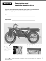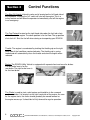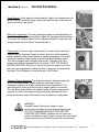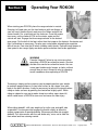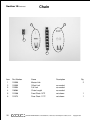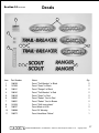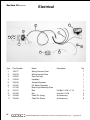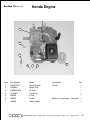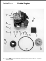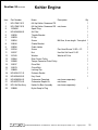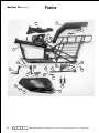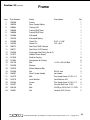
1
Illustrated
Owners and Parts Manual
Made In
The USA
ROKON International Inc.
50 Railroad Avenue
Rochester, NH 03839
Tel: 603 335-3200
Fax: 603 335-4400
e-mail:[email protected]
web site: www.rokon.com
©2005 Rokon International, Inc. Printed in U.S.A. ROKON® and its logo are registered trademarks.
Rev. 3
Welcome to the growing group of ROKON owners. All operators must read and familiarize
themselves with this owners manual and the safety information.
The ROKON Warranty Statement is enclosed with this manual. For it to be validated, the
complete ROKON Utility Vehicle Registration Card must be signed and returned to
ROKON within 10 days of the date of purchase.
We congratulate you on your decision to purchase a ROKON Utility Vehicle. By following
the procedures and suggestions outlined in this manual, you will be rewarded with many
hours of reliable, gratifying performance that others have come to expect from ROKON
Utility Vehicles.
ROKON INTERNATIONAL, 50 Railroad Ave., Rochester, New Hampshire 03839, U.S.A.
Copyright 2004
BEFORE YOU OPERATE YOUR NEW ROKON, THE
FOLLOWING IMPORTANT POINTS MUST BE OBSERVED.
1.
Children under 16 should not operate a ROKON.
2.
Carefully read and follow the instructions in the safety section of this manual.
3.
Carefully read and follow the setup procedure on the yellow card
attached to your ROKON (See yellow card instructions, also on page
56 of this manual).
4.
Follow the Pre-Operation Checklist.
TABLE OF CONTENTS
SECTION:
Page
1.
Safety Information
3-4
2.
Description and Machine Identification
5
3.
Control Functions
6-7
4.
Pre-Operation Checks
8
5.
Operating Your Rokon
9-10
6.
Periodic Maintenance and Adjustment
11-15
7.
Repair Procedures
16-21
8.
Torque and other specification charts
22
9.
Limited Warranty
23
10. Illustrated Parts Manual
ROKON INTERNATIONAL, 50 Railroad Ave., Rochester, New Hampshire 03839, U.S.A.
24-53
Copyright 2004
Section 1
Safety Information
Always wear an approved motorcycle helmet that fits properly, eye protection (goggles
or face shield), gloves, sturdy boots, long sleeve shirt, jacket and pants while operating a
ROKON.
Never consume alcohol or drugs before or while operating a ROKON.
The ROKON is a go slow vehicle. Never operate at speeds too fast for your skills or the
conditions. Always operate at a speed that is appropriate for the terrain, visibility and
operating conditions and your experience.
DANGER-SERIOUS INJURY MAY RESULT! Never attempt wheelies, jumps or other
stunts of any kind while operating a ROKON.
Always keep both hands on the handlebars during operation.
Always go slow and be extra careful when operating on unfamiliar terrain. Always be
alert to changing terrain conditions when operating a ROKON.
Never operate on excessively rough, slippery or loose terrain until you have learned and
practiced the skills necessary to control the ROKON on such terrain.
Never operate on hills too steep for the ROKON or for your abilities. Never exceed a
60% grade (or 31 degrees). Practice on smaller hills before attempting larger hills.
Always follow proper procedures for climbing hills as described in this manual. Check
the terrain carefully before you start up any hill. Never climb hills with excessively slippery or loose surfaces. Shift your weight forward when on an incline.
Always follow proper procedures for going down hills and for braking on hills as described in this manual on pages 9 and 10. Check the terrain carefully before you start
down any hill. Shift your weight rearward. Never go down a hill at high speed. Shift into
1st range and keep the torque converter engaged for engine braking as described on
page 9 in this manual. Use the rear brake only in down hill corners. Apply the rear brake
before the front brake when going straight down.
Always maintain proper tire pressure.
Never modify your ROKON. Use only ROKON parts. Follow instructions, and properly
install ROKON parts.
ROKON INTERNATIONAL, 50 Railroad Ave., Rochester, New Hampshire 03839, U.S.A.
Copyright 2004
3
Section 1 Continued
Safety Information
WARNING:
Potential bodily injury.
Never operate a ROKON without
the chain guards and side covers
in place and securely attached with
all fasteners properly tightened.
Never exceed the stated load capacity. Cargo should be properly distributed and securely attached. Reduce speed and follow instructions in this manual for carrying cargo
or pulling a trailer. Be careful to allow greater distances for braking when carrying cargo
or operating with a trailer.
Read your engine manual completely and follow all safety instructions.
WARNING:
Potential Hazard- Improper Handling of Gasoline
can catch fire and you could be burned.
Always turn off the engine when refueling. Do not refuel right after the engine has been
running and is still very hot. Do not spill gasoline on the engine or exhaust pipe/muffler
when refueling. Never refuel while smoking, or while in the vicinity of sparks, open
flames or other sources of ignition such as the pilot lights of water heaters and clothes
dryers. When transporting the machine in another vehicle be sure that it is kept upright
and that the fuel cock is in the “OFF” position (see page 6 of manual). Otherwise, fuel
may leak out of the carburetor and flood the engine.
Gasoline is poisonous and can cause injuries. If you should swallow some gasoline
or inhale a lot of gasoline vapor, or get some gasoline in your eyes, see your doctor
immediately. If gasoline spills on your skin, wash with soap and water. If gasoline spills
on your clothes, change your clothes.
WARNING
Potential Hazard- Starting or running the engine
in a closed area.
Exhaust fumes are poisonous and may cause loss of consciousness and death within
a short time. Always operate your machine in an area with adequate ventilation
4
ROKON INTERNATIONAL, 50 Railroad Ave., Rochester, New Hampshire 03839, U.S.A.
Copyright 2004
Section 2
Description and
Machine identification
Record the Vehicle Identification number and Engine Number in the spaces below to
facilitate ordering spare parts or for reference if the vehicle is stolen
VIN
Engine Number
The Engine number
is on the front of the
engine facing the
front wheel.
The Vehicle identification number
is on the center frame tube beneath
the driver seat.
ROKON INTERNATIONAL, 50 Railroad Ave., Rochester, New Hampshire 03839, U.S.A.
Copyright 2004
5
Section 3
Control Functions
The Shut Off Switch is black in color and is located on the left hand side of
the handlebar. Pressing the “kill” switch will shut off the engine. This is a
safety feature and will allow the operator to immediately shut off the engine
in an emergency.
The Fuel Petcock located on the right hand side under the fuel tank shuts
off fuel flow to the engine. The down position is for fuel flow. The up position
shuts fuel off. Shut the fuel off when storing or transporting your ROKON.
Throttle. The engine is accelerated by twisting the throttle grip on the right
hand side of the handlebar counterclockwise. The throttle grip is spring
loaded and will automatically close the throttle and slow the engine when
released.
Brakes. The ROKON Utility Vehicle is equipped with separate front and rear disc brakes.
The left brake lever is for the
rear brake. The right brake lever is
for the front brake.
The Choke is used to start a cold engine and should be in the rearward
position to choke. It is located on the right hand side of the engine. As soon
as the engine starts, the choke should gradually be moved forward as
the engine warms up. It should be left fully forward for regular operation.
6
ROKON INTERNATIONAL, 50 Railroad Ave., Rochester, New Hampshire 03839, U.S.A.
Copyright 2004
Section 3 Continued
Control Functions
Recoil Starter. Firmly grasp the handle and pull slightly until engagement can
be felt. Then pull forcefully, being careful not to pull the rope all the way out.
Return the starter rope gently.
Rider Seat Suspension. The seat suspension spring can be adjusted to suit
the rider’s weight and riding conditions. Adjust the spring per load as follows:
To increase the spring preload, turn the adjuster clockwise. To decrease the
spring preload, turn the adjuster counterclockwise.
Transmission: The three range transmission is a ratio selector and when
coupled with the automatic torque converter, gives the vehicle extremely
broad capabilities, from steep climbing to normal transporting. The torque
converter provides a large overlap of speed and torque between gears.
This makes frequent gear changes unnecessary. Therefore, the transmission has not been designed to shift in motion. STOP THE VEHICLE
BEFORE SHIFTING. Shift only at low idle or when the engine is off. Feel
the gears into engagement, rocking the bike, if necessary, to synchronize
the gears. The shift pattern is from inside out: 3-N-2-N-Low.
Automatic Torque Converter: The torque converter is designed especially
for ROKON and provides smooth automatic clutching and ratio
changing in response to throttle control and terrain requirements. The
front drive pulley tends to shift into high as engine speed is increased.
The rear driven pulley follows this speed change. If torque requirements
increase, the cam in the torque-sensing rear pulley overrides the front
pulley and forces a down shift without a loss of engine revs and power.
WARNING:
Potential Hazard- Starting the engine in gear.
could cause the Rokon to move forward unexpectedly.
PUT THE TRANSMISSION IN NEUTRAL BEFORE
STARTING THE ENGINE. Stand on the left hand side,
put the front Brake on with 2 fingers of your left hand, throttle
closed, reach over the ROKON and pull the starter handle.
ROKON INTERNATIONAL, 50 Railroad Ave., Rochester, New Hampshire 03839, U.S.A.
Copyright 2004
7
Section 4
Pre-operation Checks
Before using this machine, check the following points.
Front and Rear Brake. Check brake action. Check pucks to see that they are not over
worn. There should be visible brake material on both sides of the brake disc. See
Section 6.
Fuel Tank. Check fuel level. Fill as necessary. Use super unleaded for altitudes above
10,000 ft.
Engine Oil. The engine holds .6 qt. of SAE10W30/40 motor oil. Fill to the dipstick “full”
line.
Miter Box and Transmission. They are filled at the factory and need not be checked at
the start. The miter box should have 2.5 oz. of EP 80W90 gear lube oil. The transmission takes 6 oz. of EP 80W90 gear lube oil. The transmission has a fill to plug near the
bottom of the transmission( shown on page 46). There is no fill level for the miter box.
Over filling of either the miter box or transmission will result in leakage.
Throttle. Check for proper throttle cable operation. Look for smooth response to twist
action.
Wheels and Tires. Check Tire pressure, wear and damage.
Fittings and Fasteners. Check all fittings and fasteners.
Drive Chains. Check chains for tension and lubrication. Adjust tension for 1/2” - 3/4”
deflection at mid point.
Engine Manual. Read your engine manual completely and follow all instructions.
FAILURE TO INSPECT YOUR ROKON BEFORE OPERATION
INCREASES THE POSSIBILITY OF AN ACCIDENT OR EQUIPMENT
DAMAGE. ALWAYS INSPECT YOUR ROKON EACH TIME YOU USE IT
TO MAKE SURE IT IS IN SAFE OPERATING CONDITION.
8
ROKON INTERNATIONAL, 50 Railroad Ave., Rochester, New Hampshire 03839, U.S.A.
Copyright 2004
Section 5
Operating Your ROKON
When starting your ROKON, place the range selector in neutral.
Stand on left hand side, put the front brake on with two fingers of
your left hand, throttle closed, reach over the Rokon and pull the
starter handle. For a cold start put the choke on. Once the engine
turns over, set the choke off. Pull on the starter again and the
vehicle will start. Engage the three-range selector in the desired
gear range. Put the ball of the foot, rather than the instep on the footrest. Accelerate and
ride. Use braking as necessary. Pre-plan your route before attempting to negotiate
difficult terrain. Lean into the hill when climbing switch backs. Descend steep slopes at
slow speed in low range. Apply rear brake pressure before front brake application.
WARNING
Potential Hazard: Failure to use extra care when
operating a ROKON on unfamiliar terrain. Go slow
and be extra careful on unfamiliar terrain. You can
come upon hidden rocks, bumps, or holes, without
enough time to react. Always be alert to changing
terrain conditions when operating a ROKON.
Traversing a sloping surface requires you to properly position your weight
to maintain proper balance. As you travel across or up a slope, lean your
body in the uphill direction. It may be necessary to correct the steering when
riding on loose surfaces by pointing the front wheel slightly uphill. When
riding on slopes be sure not to make sharp turns either up or down hill,
which could cause a ROKON to turn over and cause the rider injury.
When riding downhill, shift your weight as far to the rear and uphill side
as possible. Use low gear and engage the throttle slightly to allow the
engine compression to provide braking. Whenever possible ride straight
downhill. Turn into corners with the rear brake only, so as not to slide the
front wheel and lose steering control.
ROKON INTERNATIONAL, 50 Railroad Ave., Rochester, New Hampshire 03839, U.S.A.
Copyright 2004
9
Section 5 Continued
Operating Your ROKON
The ROKON can be used to cross slow moving shallow
water of up to a maximum of 24 inches in depth. Before
entering the water, choose your path carefully. Enter where
there is no sharp drop off, and avoid rocks or other obstacles
which may be slippery or upset the ROKON. Drive slowly
and carefully. Never change your
course in the middle of a stream or
you will find that slippery rocks and
currents might throw you out of balance.
If the water is over 24” in depth, always float your machine
across (hollow wheels only). Keep the air intake out of the
water to avoid flooding the engine compartment.
Riding over rough terrain should be done with caution. Look out for obstacles which
could cause damage to the ROKON or lead to an
upset or an accident. Avoid jumping the ROKON
as loss of control and damage may result.
The real secret to riding perfection is throttle control.
Remember that gradual acceleration will take you
anywhere you desire with the proper gear selection.
Your throttle is designed to retract upon release of
the hand as a safety measure for the rider. Always
grasp your throttle with ease, and never with full force.
The ROKON is designed with individual disc brakes on the front and rear gear boxes.
The right hand front brake will stop both wheels through the gear train. When braking
with the front brake, the machine should be in a “straight away” position. Hard braking,
with a turned front wheel, can cause a loss of steering which can result in loss of
control. The left hand rear brake should be used more often for going down steep
slopes.
10
ROKON INTERNATIONAL, 50 Railroad Ave., Rochester, New Hampshire 03839, U.S.A.
Copyright 2004
Section 6
Periodic Maintenance
and Adjustment
Routine care of your ROKON vehicle is easily done and
is important for rider safety and vehicle longevity.
1.
Inspect all fasteners for tightness.
2.
The drive chains require adjustment at intervals, depending on the mileage and
the care which the operator has given the chains. Initial wear must be taken up
by adjustment after the first few hours of use. Total deflection should be 1/2” to 3/4”
when measured midway between the two sprockets of the most loose position.
To adjust the chains, loosen the axle bolts and the adjusting bolt lock nuts, and
turn the adjusting bolts equally in or out as required to give the chain the proper
setting. After adjusting the chain, rotate the wheel and check to make sure the
chain is aligned properly. Periodically, the chains should be removed from the
machine and cleaned in solvent and re-lubricated. They should be lubricated with
one of the chain lubricants on the market which can be applied to the chain in a
liquid form and will penetrate to the inner parts of the rollers.
3.
Clean the air filter based on use. See Engine Manual.
4.
Use normal repair procedures for tires and tubes. Re-seat the tire beads with 40
PSI , then deflate to the 3 -5 PSI operating pressure.
5.
The Miter Box and Transmission should not require service other than checking
the oil level or replacing oil seals. The Miter Box should be removed and oil
changed yearly. The Miter Box is assembled with special tooling to determine the
correct tooth engagement and backlash. It is not advisable to attempt to dismantle
the unit, unless necessary. The transmission should be drained and refilled on the
same yearly schedule. There is a drain plug on the bottom of the transmission, a
fill level plug partway up, and a fill plug on the top. The Miter box takes 2.5 fluid oz.
of EP 80W90 gear lube oil. The transmission takes 6 fluid oz. of EP 80W90 gear
lube oil.
6.
Check Belt for wear. Belts last at least a year and generally average 4-5 years.
7.
Check the throttle for full return and feel.
ROKON INTERNATIONAL, 50 Railroad Ave., Rochester, New Hampshire 03839, U.S.A.
Copyright 2004
11
Section 6 Continued
Periodic Maintenance and Adjustment
Storing your ROKON
1.
Close the gasoline shut-off valve, this will prevent fuel leakage when
transporting or storing your ROKON. This is a key item when transporting
your ROKON for example on the wheel free carrier.
2.
Start the engine and allow it to run until it stops from lack of fuel. This will use
up all the fuel in the carburetor and prevent the formation of deposits due to
evaporation of fuel.
3.
Disconnect fuel line and permit all fuel to drain from the gasoline tank.
Replace the fuel line.
Trouble Shooting
SYMPTOM
PROBABLE CAUSE
1. Twist grip sticks.
Twist grip end rubbing on handlebar.
Deposit buildup under twist grip.
Worn or broken twist grip or throttle cable.
Throttle linkage improperly adjusted.
Moisture under grip freezing in cold temp.
12
2. Chains loosen frequently.
Improperly seated chain adjustment bolts.
Loose axle bolts.
Improper chain alignment.
Chains need lubrication.
Twisted or distorted chains.
3. Excessive end play in wheel.
Loose axle bolts.
Improper axle or wheel spacer thickness.
Defective wheel bearings.
Distorted bearing retainer housing in wheel.
4. Chain scoring tire sidewall.
Improper chain alignment.
Improper axle spacer thickness.
Defective wheel bearings.
ROKON INTERNATIONAL, 50 Railroad Ave., Rochester, New Hampshire 03839, U.S.A.
Copyright 2004
Periodic Maintenance and Adjustment
Section 6 Continued
Trouble Shooting
SYMPTOM
PROBABLE CAUSE
5. Noisy driveline.
Driveline improperly seated.
Worn or broken override spring.
Worn, broken or loose carrier bearing or bearing
retainer.
Worn bosses leading into override spring.
Worn universal joint.
6. Noisy front miter box.
Low oil level.
Loose gearbox mounting bolts.
Worn or broken bevel gears.
Worn shaft bearings.
Improper gear mesh.
7. Rear wheel won’t drive.
Wheel chain off sprocket.
Sheared roll pin on drive sprocket
8. Front wheel won’t drive.
Wheel chain off sprockets.
Sheared roll pin in sprocket.
Broken override spring on driveline.
Worn bosses leading to override spring.
Defective transmission.
9. Engine stalls when
machine stops.
Debris in carburetor.
Improperly adjusted throttle linkage.
Ice in system.
Idle set too low.
10. Valve core disappears
within wheel. (only tubed tires)
Tire pressure too low.
Tube not secured by stem kit.
ROKON INTERNATIONAL, 50 Railroad Ave., Rochester, New Hampshire 03839, U.S.A.
Copyright 2004
13
Periodic Maintenance and Adjustment
Section 6 Continued
Trouble Shooting Engine
SYMPTOM
14
PROBABLE CAUSE
1. Engine will not start.
No fuel in tank or shut-off valve closed.
Spark plug not firing.
Fuel not being delivered to combustion chamber.
Engine flooded. Too much fuel in combustion
chamber.
Improper spark plug gap.
Plugged fuel filter.
2. Engine hard to start.
Water or dirt in fuel or stale fuel mixture.
Weak ignition spark.
Plugged air filter.
Engine over or under choked.
Gasket or seal leaks.
Spark plug fouled.
3. Engine starts but will
not continue to run.
Insufficient fuel supply.
Fuel line clogged.
Vent on filler cap plugged.
Dirty carburetor.
Air leak in fuel system.
Defective or fouled spark plug.
Idle screw not adjusted properly.
4. Engine misses.
Dirt in fuel system.
Spark plug fouled or defective.
Faulty magneto or improper ignition coil air gap
setting.
Idle screw not adjusted properly.
5. Engine lacks power.
Air cleaner clogged.
Incorrect spark plug – gap too wide or too narrow.
Incorrect air gap on ignition coil.
Worn or stuck piston rings or leaky head gasket.
Ice in system.
Hi altitude running. (use hi altitude jet)
ROKON INTERNATIONAL, 50 Railroad Ave., Rochester, New Hampshire 03839, U.S.A.
Copyright 2004
Periodic Maintenance and Adjustment
Section 6 Continued
Trouble Shooting Engine
SYMPTOM
PROBABLE CAUSE
6. Engine overheats.
Engine overloaded.
Oil too low in crankcase.
Incorrect spark plug.
Ignition timing over-advanced.
Scored piston or cylinder wall.
Lean Mixture.
Dirty air filter / blocked air intake.
7. Engine noisy or knocking.
Loose flywheel.
Worn bearings.
Broken or loose parts inside engine.
Lack of oil in crankcase.
8. Engine stalls under load.
Fuel line restricted or tank vent closed.
Engine overloaded.
9. Poor acceleration.
Air cleaner clogged.
Ignition timing over-advanced or retarded.
Leaking gaskets.
Air gap too wide.
Exhaust restriction.
Low compression.
10. Poor high speed performance.
Low compression.
Pre-ignition.
Spark plug or air gap improper.
Belt worn.
Brakes dragging.
ROKON INTERNATIONAL, 50 Railroad Ave., Rochester, New Hampshire 03839, U.S.A.
Copyright 2004
15
Periodic Maintenance and Adjustment
Section 6 Continued
Care and Adjustment of ROKON Brakes
General:
Rokon all wheel drive vehicles have individual front and rear disc brakes. They are cable operated
by hand levers on the handlebars. The left lever controls the rear brakes and, in the forward
direction, stops the rear wheel. The overrunning clutch in the driveline allows the front wheel to
continue rotating. The right lever operates the front brake and stops both wheels. The discs are
high mounted to keep them out of water and mud. Though small, they are powerful due to the
torque multiplication of the sprocket ratio.
Refer to the Rokon Parts Manual for help with part names and assembly sequence.
Maintenance:
The brakes operate with little or no maintenance, but work more smoothly and last longer if kept
clean and lubricated.
Be sure that all parts including the moveable pucks move freely and that the levers return fully.
Be sure that all fasteners are secure. Use self locking nuts, locktite or cotter pins on all fasteners.
Lubricate shaft and keys, push pins and cam, as needed, with a drop of motor oil.
Hitch Pin
or
Cotter Pin
FRONT
Brake Disc
Caliper
Brake Pad
Shaft
Push Pins
Key
Cable Clamp Screw
REAR
Cam
Cable Clamp Screw
16
Cam
ROKON INTERNATIONAL, 50 Railroad Ave., Rochester, New Hampshire 03839, U.S.A.
Cam Nut
Copyright 2004
Section 6 Continued
Periodic Maintenance and Adjustment
Maintenance:
Cables are plastic lined and do not require lubrication though it is OK to do so.
Be aware that a drop of water in a cable may freeze and prevent braking. Use boots and
lubricants to prevent this. Test before riding off in freezing weather.
Replace pucks when they are down to 1/4 inch thick. The moveable puck is loose, but the
stationary puck is secured to the caliper with a small slotted head screw. Locktite this screw.
Adjustment:
New Pucks.
After installing new pucks, reassemble the calipers and securely tighten the two 5/16” screws.
Remove the cotter pin and finger tighten the cam nut so that the cam push pins are at the bottom
of the cam. This is the starting point. Now at the hand lever, set the cable housing adjusting
screw out about 1/4 inch and lock it up by finger tightening the lock nut. At the cam, loosen the
cable clamp screw and pull the cable through snugly and clamp it up. Now loosen the cam nut so
you can ride with a few fingers holding the brake lever, but with enough lever stroke left for locking
up the brakes if need be. Check for good braking and snappy return.
In The Field.
A quick adjustment for brake wear can be made without tools at the handlebar by loosening its
locknut and extending the cable housing adjusting screw. Retighten the locknut. It is best not to go
too far with his adjustment as the overextended adjustment screw may then get hit and broken.
When you can, return the cable housing adjusting screw to its normal 1/4 inch extension and take
up pad wear at the caliper by pulling the hitch or cotter pin, tightening the cam retaining nut and
replacing the pin.
Brake Lever
Lock Nut
Cable Housing
Adjusting Screw
Cable Housing
ROKON INTERNATIONAL, 50 Railroad Ave., Rochester, New Hampshire 03839, U.S.A.
Copyright 2004
17
Section 7
Repair Procedures
I. TRANSMISSION AND DRIVELINE REMOVAL PROCEDURE
Section 1, Procedure for transmission removal:
18
1.
Elevate and secure the bike firmly to a non-moving stand. Bike should be elevated
so that the rear wheel is not touching the ground.
2.
Remove all fiberglass side covers from the bike.
3.
Shut fuel valve. Disconnect fuel line and plug, if necessary. Remove fuel tank.
4.
Remove front seat. This is accomplished by removing the two attaching bolts on
each side of the front seat bracket and the bottom shock absorber attaching bolt.
The whole assembly can be removed and put aside.
5.
If transmission and driveline need to be removed, the rear wheel and rear fender
will need to be taken off the bike. If only the transmission needs to be removed,
the rear wheel may stay intact. See Section 2 for Drive Line Removal.
6.
Remove the rear drive chain by locating the master link and separating it from the
chain.
7.
Remove the rear driveline roll pin. (If transmission and driveline are to be taken
out as one unit, leave roll pin attached for ease of disassembly.) This is done by
inserting a pin punch into the roll pin access hole (located under the front seat,
which was removed), and driving the pin straight downward. Note: Rotate rear
wheel until hole lines up.
8.
Remove drive belt.
9.
Remove driven clutch. Loosen the three Allen screws behind the clutch. Note:
Driven clutch may be frozen on to the shaft. A small piece of wood and a mallet
from behind the clutch should ease removal. Care must be taken, not to damage
clutch. Use pry bars if necessary.
10.
Remove muffler header pipe. (Loosen two 12mm nuts. Pull muffler off engine seat.
Pull muffler out of sleeve).
11.
Remove rear brake caliper assembly. Take caution not to undo the brake line
from the spring assembly. Disconnect cotter pin and back off brake tension.
Remove brake caliper assembly and brake bracket as a complete unit. (Remove
the two 1/2 “ bolts under the brake disc.). Slide Brake Disc off shaft. Take note
the way the caliper and brake disc came off for reassembly.
ROKON INTERNATIONAL, 50 Railroad Ave., Rochester, New Hampshire 03839, U.S.A.
Copyright 2004
Section 7 Continued
12.
Repair Procedures
Remove all four transmission attaching bolts, three on the frame mount, and one
next to the upper cross shaft. (Two should already be removed from the brake
bracket as described in step 11).
At this point: Transmission can be removed, by moving left to right to loosen
it from the Driveline clutch, sliding back into fender well, and carefully turning
sideways and pulling upward. Note: If the transmission can be shifted into 3rd
gear, it will ease removal, by having the shift ball closer to the transmission.
Reverse disassembly procedure for assembling.
Note: Replace worn parts as needed. (ie.: roll pins, Worn nuts or bolts, drive belt, etc.)
Use thread lock compound on transmission bolts upon reassembly.
Section 2, Procedure for Transmission and Driveline Removal:
1.
Follow steps 1-5 in Section 1.
2.
Remove in order: rear wheel, tail section of muffler, and rear fender.
3.
Remove the two carrier bearing bolts, which are located under the fuel tank.
4.
Remove front chain guard cover, front drive chain, and headlight. Note: Ground
wire for the headlight must be routed behind front miter box assembly.
5.
Remove front brake caliper assembly. Note: Take caution not to undo the brake
line from the spring assembly. Disconnect cotter pin and relieve brake tension.
Remove two 1/2” bolts that secure the assembly to the bracket. Swing out of the
way. Remove brake disc.
6.
Remove front miter box assembly. (This is done by removing the two 1/2” bolts
from behind the miter box assembly.) Pull miter box assembly straight out of
bore, with universal joint attached. Set aside.
7.
Remove transmission assembly and drive line as one unit (Ease disassembly by
making sure the transmission is shifted into the highest gear. Shift ball closest to
the transmission.) Pull the assembly straight out of the bore.
8.
Reverse procedure for reassembly.
ROKON INTERNATIONAL, 50 Railroad Ave., Rochester, New Hampshire 03839, U.S.A.
Copyright 2004
19
Section 7 Continued
Repair Procedures
II. Front Miter Box and Universal Joint Removal Procedure
20
1.
Remove front chain guard and front chain. Use a 1/2-inch wrench or socket to
remove chain guard. Then find master link and loosen chain. Remove master
link. Take chain off.
2.
Remove headlight. Using 1/2 inch wrench loosen and remove nut that attaches
light to fender. Unplug power lead & disconnect ground that is attached at miter
box mounting bolt. Set aside.
3.
Remove brake caliper and disc. Using 1/2 inch wrench & socket remove both
bolts that hold caliper in place. Remove caliper & replace bolt and nuts to keep
pucks in place and let caliper hang off the side of the bike & remove brake disc.
4.
Remove miter box. At this point you should have removed the bolt on the left
side of the bike (this attached ground for headlight). Remove the left bolt and
pull miter box straight out (the universal joint will come with the miter box).
5.
Replace broken or worn parts as needed including universal joint, gears or seals.
6.
After repairs are made and with the universal joint in place, slide miter box
(gently) into place. You will feel it hit the drive shaft. Slide your index & middle
fingers of your right hand between the fork and where the universal joint is
located. Pinch the universal joint with these two fingers. Slide the brake disc into
place and use this to spin miter box. As you are spinning miter box you should
feel it locate itself on the woodruff key as it catches back into place. To make
sure the universal joint is located properly, lock the rear brake and spin disc
counter clockwise. If the disc doesn’t spin, it has been installed properly. If the
miter box does spin, remove and check to see if woodruff key is in place. If it has
slipped out, you can retrieve the key by tilting the bike up on its nose and it will
fall out. Replace the key by means of long needle nose pliers or your finger and
repeat the procedure.
7.
When you have the miter box installed properly, reverse procedure 1-5.
ROKON INTERNATIONAL, 50 Railroad Ave., Rochester, New Hampshire 03839, U.S.A.
Copyright 2004
Repair Procedures
Section 7 Continued
III. FRONT DRIVE LINE SYSTEMS CHECK
1.
Elevate bike so wheels are not touching the ground.
2.
Apply front brake.
3.
Rotate rear tire in forward direction.
4.
While rotating rear tire (in forward direction), check front universal joint for
rotation. If the universal joint is spinning, check roll pin that attaches front drive
sprocket. If roll pin is not damaged, then the internal miter box roll pin is sheared.
If the universal joint is not spinning, look into rear inspection holes, under the
seat, to see if slip clutch is turning.
5.
If slip clutch turns then the roll pin attaching the drive shaft to the slip clutch is
sheared. If slip clutch is not spinning, check to see if roll pin attaching slip clutch
to the transmission is sheared. If roll pin is not sheared, then an internal
transmission roll pin is sheared.
6.
If miter box is damaged, it must be removed. Miter box must be disassembled
and repaired as needed.
7.
If this roll pin connecting the drive shaft to the slip clutch is sheared, it is
recommended that the drive shaft be replaced. Line up pin hole and replace.
8.
If the internal transmission damage is suspected, transmission must be removed
and repaired as necessary. Contact ROKON for transmission repair.
ROKON INTERNATIONAL, 50 Railroad Ave., Rochester, New Hampshire 03839, U.S.A.
Copyright 2004
21
Section 8
Torque and other
Specification Charts
Torque and Threadlocking Specifications For Fasteners On Rokon 2WD Vehicles
Fastener
Size
10-32
Location
Foot Rest Tube
Thread locking
Lock Washer
Torque
In. lbs.
Ft. lbs.
25
2
84
7
180
15
360
30
720
60
2400
200
M5
25
2
M6
84
7
M8
180
15
M10
360
30
1/4
5/16
3/8
Transmission
Loctite 242 + Lock Washer
Brake Mounting
Self Locking Nuts
Wheel Bearings
Loctite 242
Foot Rest
Self Locking Nuts
Engine Mounting
1/2
3/4
Steering
Loctite 242
Miscellaneous Specs
Tire Pressure 3 - 5 PSI
See Engine Manual for engine details.
22
ROKON INTERNATIONAL, 50 Railroad Ave., Rochester, New Hampshire 03839, U.S.A.
Copyright 2004
Section 9
Limited Warranty
ROKON WARRANTY SYSTEM
ROKON International Inc. warranties to the original purchaser, new ROKON Utility vehicles to be
free of defects that are the result of faulty workmanship or material, for a period of one year from the
date of purchase for new year model ROKONs only. In the case of competition machines, no
warranty is expressed or implied. The entire risk to the quality and performance of competition
machines is with the buyer.
Warranty will be honored through any authorized ROKON dealer or the factory. To validate warranty,
Purchaser must: Complete and return Warranty registration Card to ROKON International, Inc.
within ten (10) days of purchase.
Notify ROKON of any and all defects made within ten (10) days of malfunction and make machine
immediately available for inspection at a place to be determined by ROKON.
Have warranty service performed by an authorized Rokon agent as directed by ROKON.
Warranty will not cover:
Parts replaced as a result of normal wear. (ie.: spark plugs, tires, tubes , and so forth)
Parts subject to misuse, neglect, or modification.
Parts damaged as a result of accident or collision.
Machines used for rental and/or lease.
Machines used in competitive events.
Machine abuse.
ROKON International Inc.’s liability shall be limited to that set forth herein, and no other claims for
consequential damage or injury to person or property will be admissible. All other conditions and
warranties, statutory or otherwise, and whether expressed or implied, including, but not limited to,
implied warranties of merchantability or fitness for a particular use, are hereby excluded. This implied
warranty exclusion is not applicable in states having laws to the contrary.
ROKON INTERNATIONAL, 50 Railroad Ave., Rochester, New Hampshire 03839, U.S.A.
Copyright 2004
23
Section 10
Illustrated Parts Manual
Index of Illustrations
Page
25
26
27
28
29
30 & 31
32 & 33
34
35
36
37
38 & 39
40
41
42
43
44
45
46
47
48 & 49
50
51
52
53
54
24
Nomenclature
Brakes
Chain Parts
Decals
Electrical
Engine Honda
Engine Kohler
Frame
Front fork
Cargo Rack Assembly
Fuel Tank Assembly
Muffler
Handlebar Assembly
Pullstarter
Front Seat
Rear Seat
Torque Converter Drive Pulley
Torque Converter Driven Pulley
Tow Bar
Transmission Complete
Transmission with Attachments
Transmission in Sequence
Miter Box
Transmission to Miter Box
Aluminum Wheels
Steel Wheels
Wiring Diagram
ROKON INTERNATIONAL, 50 Railroad Ave., Rochester, New Hampshire 03839, U.S.A.
Copyright 2004
Section 10 Continued
18
Brake
17
2
5
7
6
1
4
10
16
16
11
5
14
Item
1
2
3
4
5
6
7
8
9
10
11
12
13
14
15
16
17
18
19
20
21
Part Number
108023
108024
108025
108026
108027
108028
108029
108030
108031
108032
108033
108002
100788
100509
100169
100202
108982
101673
100481
108002
100254
21
15
Name
Live Side Housing
Compression Spring
Lever Arm
Locking Nut
Actuating Pin
Back Plate
Dead Side Housing
Dead Side Puck
Flat Head Screw
Hex Head Bolt
Live Side Puck
Caliper Assembly
Brake Spring
Brake HH Bolt
Nut
Washer
Castle Nut
Cotter Pin
Brake Puck Set
Brake Caliper Assy.
Washer
3
8
16
13
Description
1/4-28 x 3/4 Hole for Cable
5/16
Includes 108030 & 108033
Includes everything except 13
1/4
ROKON INTERNATIONAL, 50 Railroad Ave., Rochester, New Hampshire 03839, U.S.A.
Copyright 2004
Qty
1
1
1
2
2
1
1
1
1
2
1
1
1
1
1
4
1
1
1
1
25
Chain
Section 10 Continued
1
2
3
4
Item
1
2
3
4
5
6
26
Part Number
100356
100355
100354
108984
101568
101570
Name
Master Link
Offset Link
Full Link
Chain Length
Front Chain 107P
Rear Chain 117P
Description
Qty
2
as needed
as needed
as needed
not shown
not shown
ROKON INTERNATIONAL, 50 Railroad Ave., Rochester, New Hampshire 03839, U.S.A.
1
1
Copyright 2004
Section 10 Continued
Decals
7
10
9
1
4
6
8
5
Item
1
2
3
4
5
6
7
8
9
10
11
Part Number
108039
101595
108041
108040
108043
108990
108991
101626
108057
108988
108972
2
3
Name
Decal "Trail-Breaker" in Black
Decal "Scout" in Black
Decal "Ranger" in Black
Decal "Trail-Breaker" in Red
Decal "Scout" in Red
Decal "Rokon" Oval in Red
Decal "Rokon" Oval in Brown
Decal "Shift Instructions"
Decal Made in USA
Decal Oil Warning
Decal Handlebar “Rokon”
ROKON INTERNATIONAL, 50 Railroad Ave., Rochester, New Hampshire 03839, U.S.A.
Qty
2
2
2
2
2
2
2
1
2
1
1
Copyright 2004
27
Section 10 Continued
Electrical
4
2
3
8
1
9
7
6
5
Item
1
2
3
4
5
6
7
8
9
10
11
28
Part Number
108177
108178
104315
104313
108126
100190
101135
100170
100169
100448
100449
Name
Wiring Harness Front
Wiring Harness Rear
Rear Tail Light
Headlight
Voltage Regulator
Kill Switch Assembly
Brake Light Mounting Plate
Bolt
Nut
Cable Tie (Long)
Cable Tie (Short)
10
Description
HH Bolt 1/4-28 x 1 1/2
Lock Nut 1/4-28
As Necessary
As Necessary
ROKON INTERNATIONAL, 50 Railroad Ave., Rochester, New Hampshire 03839, U.S.A.
Copyright 2004
Qty
1
1
1
1
1
1
1
2
2
2
6
Honda Engine
Section 10 Continued
1
4
2
6
Item
1
2
3
4
5
6
7
Part Number
HONGX160
100369H
HON5247408
101548H
108253
108254
108256
7
3
5
Name
Honda Engine
Spark Plug
Air Filter
Crank Key
E Clip
Screw
Cable Holder
Description
GX160
Qty
1
1
1
1
1
M4 Size, 6 mm length, .7mm pitch 1
1
ROKON INTERNATIONAL, 50 Railroad Ave., Rochester, New Hampshire 03839, U.S.A.
Copyright 2004
29
Kohler Engine
Section 10 Continued
1
23
19
18
3
7
6
5
10
12
11
8
4
9
16
17
14
30
15
ROKON INTERNATIONAL, 50 Railroad Ave., Rochester, New Hampshire 03839, U.S.A.
13
Copyright 2004
Section 10 Continued
Item
1
2
3
4
5
6
7
8
9
10
11
12
13
14
15
16
17
18
19
20
21
22
23
Kohler Engine
Part Number
KOH PA911512
KOH PA911513
100369K
KOH6308306-S
108235
108253
108254
108246
108256
100034
100037
100165
100884
100885
108137
108123
108983
KOH6304121-S
KOH6334005-S
KOH6385304-S
KOH6375704-S
KOH Air Box Assy
108968
Name
Description
Qty
6.6 Hp Kohler Command PS
1
6.6 Hp Kohler Command ES not shown
1
Spark Plug
1
Air Filter
1
Throttle Bracket
1
E Clip
1
Screw
M4 Size, 6 mm length .7mm pitch 1
Choke Bracket
1
Cable Holder
1
Screw
Pan Head Screw 10-32 x 1/2
1
Nut
Hex Nut Self Lock 10-32
1
Washer
Washer #10 flat
1
Rear Driven Pulley
1
Torque Converter Drive Pulley
1
Drive Belt
1
Clutch Bolt
1
Locking Clip
1
Exhaust Gasket
1
Key Crank
1
Carburetor Complete
not shown separately
Carburetor Repair Kit
not shown
Kohler Air Box Assembly
not shown separately
Nylon Snap In Plug
1
ROKON INTERNATIONAL, 50 Railroad Ave., Rochester, New Hampshire 03839, U.S.A.
Copyright 2004
31
Frame
Section 10 Continued
2
4
21
22
5
21
22
1
23
19
24
13
26
9
10
11
17
25
16
6
18
8
7
14
12
15
32
3
ROKON INTERNATIONAL, 50 Railroad Ave., Rochester, New Hampshire 03839, U.S.A.
Copyright 2004
Section 10 Continued
Item
1
2
3
4
5
6
7
8
9
10
11
12
13
14
15
16
17
18
19
20
21
22
23
24
25
26
Part Number
105066
108243
108994
108995
108996
100386
100223
100285
100290
108272
108271
100343
101572
101629
101630
100126
100255
100573
100036
108087
100273
100275
100034
100037
108123
100551
Frame
Name
Frame
Rear Fender Kohler
Fairing LHS
Fairing RHS Front
Fairing RHS Rear
Kickstand
Kickstand Spring
Clevis Pin
Cotter Pin
Foot Rest RHS Cleated
Foot Rest LHS Cleated
Passenger Foot Rest (Set of 2)
Rubber Chain Guard
Stud for Fairing
Receptacle for Fairing
Bolt
Washer
Wheel Adjuster Bolt
Nut
Rear Fender Honda
Bolt
Lock Washer
Screw
Nut
Bolt
Nut
Description
Qty
1
1
1
1
1
1
1
5/16" x 1 3/8"
1
1/8" x 3/4"
1
1
1
1
1
6
6
1/4-20 x 5/8 HH Bolt
2
2
2
3/8-24 Jam
2
not shown
1
Pan Head Screw 10-32 x 1/4
6
Lock Washer #10
6
Pan Head Screw 10-32 x 1/2
2
Hex Nut Self Lock 10-32
2
HHCS gr 5 5/16-24X 1 1/2 ZN
2
Locknut 5/16-24 Hex
2
ROKON INTERNATIONAL, 50 Railroad Ave., Rochester, New Hampshire 03839, U.S.A.
Copyright 2004
33
Section 10 Continued
Front Fork
6
5
4
2
1
15
11
14
12
5
17
7
16
13
3
9
10
Item
1
2
3
4
5
6
7
8
9
10
11
12
13
14
15
16
17
34
Part Number
105064
100453
100935
103136
100772
107026
107025
100573
100036
100427
108106
101629
101630
100035
100037
100167
100169
8
8
9
Name
Front Fork Weldment
Front Fender
Pop Rivet
Snap Ring
Bearing
Upper Fork Bolt
Lower Fork Bolt
Wheel Adjuster Bolt
Nut
Front Mud Flap
Front Chain Guard
Stud
Receptacle
Screw
Nut
Bolt
NutLock
Description
Sealed
Use Locktite 242
Use Locktite 242
HH Bolt 3/8-24 x 1 3/4
Fully Threaded
Hex Nut Jam 3/8-24
Pan Head Screw 10-32 x 1 1/2
Hex Nut Self Lock 10-32
1/4-28 x 1/2 HH Bolt
Nut 1/4-28
ROKON INTERNATIONAL, 50 Railroad Ave., Rochester, New Hampshire 03839, U.S.A.
Copyright 2004
Qty
1
1
5
1
2
1
1
2
2
1
1
1
1
2
2
1
1
Section 10 Continued
Front Cargo Rack
3
1
2
6
5
4
Item
1
2
3
4
5
6
7
Part Number
100423
100167
100281
100170
100255
100169
100892
Name
Front Cargo Rack
Screw
Washer
Screw
Washer
Nut
Front Cargo Rack Kit
Description
HH 1/4-20 x 1/2
1/4" Lock Washer
HH 1/4-28 x 1 1/2
1/4 x 28 Locking
Includes all items above
ROKON INTERNATIONAL, 50 Railroad Ave., Rochester, New Hampshire 03839, U.S.A.
Copyright 2004
Qty
1
2
2
2
2
2
35
Section 10 Continued
Fuel Tank
1
5
7
8
6
2
4
3
9
5
Item
1
2
3
4
5
6
7
8
9
10
11
12
13
14
36
Part Number
103120-GR
102843
102766
101295
100122
102594
102593
102590
101969
101970
102589
103120-RED
103120-OD
103120-BLK
11
5
10
Name
Fuel Tank Forest Green
Fuel Cap
Fuel Filter
Shut off Valve
Fuel Line
O Ring
Nut
Fuel Tank Fitting
Rubber Fuel Tank Washer
Bolt
Flat Washer
Fuel Tank Red
Fuel Tank Olive Drab
Fuel Tank Black
Description
Qty
1
1
1
1
3
1
1
1
1
1
1
9/16"-18
HH 1/2-20 x 3/4
not shown
not shown
not shown
ROKON INTERNATIONAL, 50 Railroad Ave., Rochester, New Hampshire 03839, U.S.A.
Copyright 2004
Section 10 Continued
Muffler
1
4
3
5
4
1
Item
1
2
3
4
5
6
Part Number
108236
108150
108998
108997
100255
KOH6331402-S
Name
Muffler Kohler
Muffler Honda
Sandwich Mount
Nut
Washer
Muffler Guard
Description
not shown
1/4-20 Jam Nut Nylock
Qty
1
1
2
4
2
not shown
ROKON INTERNATIONAL, 50 Railroad Ave., Rochester, New Hampshire 03839, U.S.A.
Copyright 2004
37
Section 10 Continued
Handle Bar
2
12
16
4
1
21
21
3
3
15
14
17
18
17
14
15
18
19
20
6
5
11
11
7
10
10
7
13
8
38
ROKON INTERNATIONAL, 50 Railroad Ave., Rochester, New Hampshire 03839, U.S.A.
Copyright 2004
Section 10 Continued
Item
1
2
3
4
5
6
7
8
9
10
11
12
13
14
15
16
17
18
19
20
21
Part Number
100466
100071
100820
107036
100015B
100014HB
108002
108234
108001
100610
100788
100559
100043
104309
107033
103113
108173
108174
108115
108116
103116
Handle Bar
Name
Handlebar
Grip Set
Brake Lever
Throttle Cable
Front Brake Cable
Rear Brake Cable
Brake Caliper
Rear Brake Bracket (Kohler Only)
Rear Brake Bracket (Honda Only)
Brake Disc
Brake Spring
Throttle Spring
Woodruff Key
Brake Switch
Boot
Twist Grip
Handlebar Clamp Bolt Short
Handlebar Clamp Bolt Long
Handlebar Clamp Upper
Handlebar Clamp Lower
Cable Adjuster
Description
Qty
1
1
2
1
1
1
2
1
1
2
2
1
2
2
2
1
2
2
2
2
2
not shown
#9
3/8-24 x 1 1/2
3/8-24 x 2 1/4
ROKON INTERNATIONAL, 50 Railroad Ave., Rochester, New Hampshire 03839, U.S.A.
Copyright 2004
39
Section 10 Continued
Pullstarter
7
1
5
9
3
8
4
6
Item
1
2
3
4
5
6
7
8
9
10
40
Part Number
KOH6308619-S
KOH6316502-S
KOH6308105-S
KOH6316601-S
KOH6308921-S
15585
KOH6309302-S
KOH6375706-S
KOH6308652-S
KOH6310902-S
Name
Screw, hex flange
Starter, retractable
Housing Assembly
Starter, handle
Recoil Spring
Pull Rope
Pulley
Kit, pawl repair
Screw
Starter Cup
Description
Qty
3
1
1
1
1
1
1
1
1
1
includes 3-9
includes 9
ROKON INTERNATIONAL, 50 Railroad Ave., Rochester, New Hampshire 03839, U.S.A.
Copyright 2004
Section 10 Continued
Front Seat
1
2
9
10
7
6
5
8
3
6
7
Item
1
2
3
4
5
6
7
8
9
10
11
11
Part Number
100451H
109002S
108063
108062
101629S
100208
101970
108999
101181
100212
100168
100169
4
5
Name
Front Seat
Shock
Seat Base Plate
Lower Shock Mount
Bolt
Washer 1/2 Flat
Bolt
Bolt
Bolt
Nut
Bolt
Nut
Description
Qty
1
1
1
1
Lag
5
2
HH Bolt 1/2-20 x 3/4
2
1
HH Bolt 3/8-24 x 1 3/4
1
Lock Nut 3/8-24
1
Not Pictured for Lower Shock Mount 2
Not Pictured for Lower Shock Mount 2
ROKON INTERNATIONAL, 50 Railroad Ave., Rochester, New Hampshire 03839, U.S.A.
Copyright 2004
41
Section 10 Continued
Rear Seat
1
2
3
3
4
Item
1
2
3
4
42
Part Number
100340
100343
100281
105037
Name
Rear Seat
Passenger Foot Peg Set
Locking Washer
Hex Head Bolt
Description
Lock Washer 1/4 Spring
HH Bolt 1/4-20 x 1 3/8
ROKON INTERNATIONAL, 50 Railroad Ave., Rochester, New Hampshire 03839, U.S.A.
Qty
1
1
4
4
Copyright 2004
Section 10 Continued
Torque Converter
Drive Pulley
1
2
5
8
6
9
7
4
10
3
12
11
13
Item
1
2
3
4
5
6
7
8
9
10
11
12
13
Part Number
703209
601319
690144
690146
703128
703116
703127
703129
703151
703211
108123
108983
100885
Name
Fixed Face and Hub Assy
Moveable Face Assy
Spring Kit
Roller Arm Kit
Liner Spline
Bearing
Washer
Retractor
Plate
Washer
Clutch Bolt
Locking Clip
Torque Converter Drive Complete
Description
not shown
not shown
Idler Bearing
Ramp Plate Retaining
Includes 1-10
ROKON INTERNATIONAL, 50 Railroad Ave., Rochester, New Hampshire 03839, U.S.A.
Copyright 2004
Qty
1
1
1
1
6
1
1
1
1
1
1
1
1
43
Section 10 Continued
Torque Converter
Driven Pulley
4
5
2
1
6
7
3
8
Item
1
2
3
4
5
6
7
8
44
Part Number
601311
703110
703109
703111
703305
601406
901709
100884
Name
Hub Fixed Face
Bearing
Movable Face
Spring
Button Shoe Ramp
Torque Bracket
Set Screw
Driven Pulley
Description
Includes Items 5 & 7
Rear Includes 1-7
ROKON INTERNATIONAL, 50 Railroad Ave., Rochester, New Hampshire 03839, U.S.A.
Copyright 2004
Qty
1
1
1
1
3
1
3
1
Section 10 Continued
Tow Bar
9
1
8
7
2
11
6
5
7
4
8
5
6
9
3
Item
1
2
3
4
5
6
7
8
9
10
11
Part Number
100349
100007
103181
100166
100255
100169
100848
100208
100551
100893
100170
Name
Tow Bar
Chain
Rigid Tow Bar
Bolt
Washer
Nut
Bolt
Washer
Nut
Tow Bar Kit
Bolt
Description
Accessory
HH 1/4-28 x 1
Lock Nut 1/4-28
HHCS 5/16-24 x 3/4
Flat Washer 3/8
Locknut 5/16-24 Hex
Includes all except 3
HH 1/4-28 x 1 1/2
ROKON INTERNATIONAL, 50 Railroad Ave., Rochester, New Hampshire 03839, U.S.A.
Copyright 2004
Qty
1
1
1
1
2
2
2
2
2
1
45
Section 10 Continued
Transmission
Complete
Fill Plug
Fill Level
Drain Plug
46
ROKON INTERNATIONAL, 50 Railroad Ave., Rochester, New Hampshire 03839, U.S.A.
Copyright 2004
Section 10 Continued
Transmission
with Attachments
1
3
4
6
5
2
6
Item
1
2
3
4
5
6
Part Number
101680
100884
100610
100040
100270
100043
Name
Transmission Assembly
Rear Driven Clutch
Brake Disc
11 Tooth Sprocket
Roll Pin
Woodruff Key
Description
ROKON INTERNATIONAL, 50 Railroad Ave., Rochester, New Hampshire 03839, U.S.A.
Qty
1
1
1
1
1
3
Copyright 2004
47
Transmission
in Sequence
Section 10 Continued
41
1
2
37
38
3
4
38
37
5
6
7
2
4
17
43
2
12
7
14
11
8
5
6
37
9
11
10
5
13
20
8
42
6
5
21
23
5
18
16
15
6
26
25
10
5
27
28
33
29
34
5
31
30
48
2
6
22
24
2
19
40
32
35
ROKON INTERNATIONAL, 50 Railroad Ave., Rochester, New Hampshire 03839, U.S.A.
Copyright 2004
Section 10 Continued
Item
1
2
3
4
5
6
7
8
9
10
11
12
13
14
15
16
17
18
19
20
21
22
23
24
25
26
27
28
29
30
31
32
33
34
35
36
37
38
39
40
41
42
43
Part Number
101502
101523
103142
103134
100158
103136
100160
100045
101519
100043
101506
103143
101517
105082-2
101511
101637
101633
101634
101632
101528
101527
101530
101541
101631-3
101631-2
101631-1
101516
107039
101505
101548
101510
100047
101509-3
101509-2
101509-1
100163
101525
101524
101939
105082
108987
101615
100163
Transmission
in Sequence
Name
Description
Transmission Casting Machined 2 halves
Oil Seal
Shaft
Front Output
Snap Ring
Bearing
Snap Ring
Miter Gear
Roll Pin
3/16" x 1 1/4"
Spacer
Woodruff Key
#9
Key
#3
Shaft
Rear Output
Gear
64T Drive
End Cap
Spacer
Roll Pin
3/32" x 1/2"
Gear Selector
Shift Rod
Selector Shaft
Spring
Ball
Spacer
Shift Knob
Gear
40T
Gear
51T
Gear
60T
Gear
32T
Shaft
Input
Snap Ring
Key
Straight Cut
Spacer
Roll Pin
3/16" x 1"
Gear
40T
Gear
29T
Gear
20T
Plug
Screw
1/4"-20 X 1"
Screw
1/4"-20 X 1 3/4"
Dowel Pin
End Cap
Pressure Relief Valve
Shim
.005
Plug
ROKON INTERNATIONAL, 50 Railroad Ave., Rochester, New Hampshire 03839, U.S.A.
Qty
1
5
1
2
8
6
2
2
1
3
3
1
1
1
1
2
1
1
1
1
1
1
1
1
1
1
1
1
1
1
1
1
1
1
1
2
1
1
2
1
1
1
2
Copyright 2004
49
Section 10 Continued
Miter Box
6
18
7
5
10
11
16
17
8
4
2
15
9
7
8
1
5
13
14
10
12
11
3
5
15
5
8
Item
1
2
3
4
5
6
7
8
9
10
11
12
13
14
15
16
17
18
50
Part Number
103131
100040
108053
103132
100158
108987
100160
101523
100270
100045
103136
101615
101616
100043
101505
100108
100853
100100
Name
Miter Box Assembly
11 T Sprocket
Miter Box Drive Shaft
Miter Box Driven Shaft
Bearing
Pressure Relief Vent
Miter Gear
Oil Seal
Roll Pin
Roll Pin
Snap Ring
Shim ID 3/4" OD 1 1/8" .005
Shim ID 3/4" OD 1 1/8" .010
Woodruff Key
Snap Ring
Spacer
Spacer
Miter Box
Description
more as needed
more as needed
Connects to Brake Disc
ROKON INTERNATIONAL, 50 Railroad Ave., Rochester, New Hampshire 03839, U.S.A.
Copyright 2004
Qty
1
1
1
1
4
1
2
3
1
2
4
1
1
1
2
1
1
1
Section 10 Continued
2
1
Transmission
to Miter Box
12
18
11
11
5
16
6
14
3
10
2
15
7
2
17
4
8
9
8
Part Number
101680
100039
100038
100307
108079
100314
100252
100281
100043
108054
100046
100100
100312
100047
101655
101656
100002
101529
100045
101640
Name
Transmission Case Assembly
Lock Washer
Screw
Snap Ring
Drive Shaft
Drive Line Bearing
Screw
Lock Washer
Drive Line Key
Universal Joint
Roll Pin
Miter Box Assembly
Bearing Retainer
Roll Pin
Drive Line Boss
Retaining Pin
Override Spring
Screw
Roll Pin
Drive Line Assembly
3
2
13
3
Item
1
2
3
4
5
6
7
8
9
10
11
12
13
14
15
16
17
18
19
20
19
7
Description
Three Speed
5/16
5/16-18 x 7/8
Four Stroke Models
1/4-20 x 1/2
1/4
#9 Woodruff
3/16 x 1 1/2
Front All Models
Drive Line Support
3/16 x 1
HH Bolt 5/16-18 x 2 1/4
ROKON INTERNATIONAL, 50 Railroad Ave., Rochester, New Hampshire 03839, U.S.A.
Copyright 2004
Qty
1
6
5
2
1
1
2
2
1
1
3
1
1
1
2
1
1
1
1
1
51
Section 10 Continued
Aluminum Wheels
1
2
4
15
14
10
9 11 10
11 9
14
12
6
7
13 15
8
3
5
17
18
16
19
Item
1
2
3
4
5
6
7
8
9
10
11
12
13
14
15
16
17
18
19
52
Part Number
100519
100836
100542
100521
108156
108129
100405
105030
100772
100522
100208
100756
100758
101181
100288
108112
100036
100523
100516
Name
Tire 5.90 X 15
Tire 8 X 12
Valve Stem
Tube
Aluminum Wheel 12"
Aluminum Wheel 15"
Axle
Valve Stem Kit
Bearing
Axle Spacer
Washer
Spacer
Spacer
Bolt
Lockwasher
Sprocket
Jam Nut
Plug
O Ring
Description
Goodyear Implement
Titan 489 XT
12" only
15" only
Qty
2
2
2
2
2
2
2
1
4
4
4
2
2
4
4
2
10
2
2
15" only (not shown)
Dead Side
Sprocket Side
3/8-24 x 1 3/4"
3/8" Lock
60T
ROKON INTERNATIONAL, 50 Railroad Ave., Rochester, New Hampshire 03839, U.S.A.
Copyright 2004
Section 10 Continued
Steel Wheels
2
1
4
14 10 13
9
7
9 13 10 14
12
12
11
11
6
8
5
3
Item
1
2
3
4
5
6
7
8
9
10
11
12
13
14
Part Number
100519
100836
100541
100521
100116
100117
100405
105030
100772
100522
100208
101181
100853
100288
Name
Tire 5.90 X 15
Tire 8 x 12
Valve Stem
Tube
Wheel
Wheel
Axle
Valve Stem Kit
Bearing
Axle Spacer
Washer
Bolt
Shim
Lockwasher
Description
Goodyear Implement
Titan 489 XT
12" only
15" only
12" Steel
15" Steel
15" only (not shown)
3/8-24 x 1 3/4"
3/8" Lock
ROKON INTERNATIONAL, 50 Railroad Ave., Rochester, New Hampshire 03839, U.S.A.
Copyright 2004
Qty
2
2
2
2
2
2
2
1
2
2
2
2
2
2
53
Section 10 Continued
54
Wiring Diagram
ROKON INTERNATIONAL, 50 Railroad Ave., Rochester, New Hampshire 03839, U.S.A.
Copyright 2004
Service/Maintenance Log
DATE
DESCRIPTION OF SERVICE
ROKON INTERNATIONAL, 50 Railroad Ave., Rochester, New Hampshire 03839, U.S.A.
Copyright 2004
55
IMPORTANT – PLEASE COMPLY WITH THE
FOLLOWING OWNER PREPARATION STEPS PRIOR
TO OPERATION OF YOUR NEW ROKON:
1)
READ AND BECOME THOROUGHLY FAMILIAR WITH THE MATERIAL
IN YOUR OWNERS MANUAL.
2)
REDUCE THE TIRE PRESSURE TO 31/2 PSI IN THE FRONT TIRE AND
21/2 PSI IN THE REAR TIRE.
3)
HANDLEBAR INSTALLATION: HANDLEBAR HAS BEEN DISASSEMBLED
FOR SHIPMENT. REINSTALL AND POSITION HANDLEBAR AND
TORQUE HANDLEBAR MOUNTING BOLTS TO 20 FT/LBS. ALL WIRES,
BRAKE CABLES AND THROTTLE CABLE MUST PASS BETWEEN
HANDLE BAR MOUNTING TOWERS.
4)
COMPLETELY FILL CRANKCASE WITH SAE 10W-30/40 MOTOR OIL.
FOLLOW START UP PROCEDURES IN ENGINE MANUAL.
5)
ADD UNLEADED FUEL TO TANK. USE SUPER UNLEADED FOR
OPERATION AT OR ABOVE 10,000 FEET.
6)
DURING THE FIRST FOUR (4) HOURS OF OPERATION, INSPECT
THE DRIVE CHAINS FOR EXCESSIVE LOOSENING. ADJUST AND
LUBRICATE DRIVE CHAINS PER OWNERS MANUAL.
50 RAILROAD AVE
ROCHESTER, NH 03839
www.rokon.com
TEL: 603-335-3200
FAX: 603-335-4400
56
ROKON INTERNATIONAL, 50 Railroad Ave., Rochester, New Hampshire 03839, U.S.A.
Copyright 2004