1
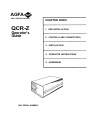
QCR-Z
Operator's Guide
Document Number: 20-21-2001
AGFA
Agfa Matrix Division One Ramland Road, Orangeburg NY, USA 10962
AGFA
AGFA MATRIX DIVISION
QCR-Z
Operator's
Guide
CHAPTER INDEX
1. PRE-INSTALLATION
2. CONTROLS AND CONNECTORS
3. INSTALLATION
4. OPERATOR INSTRUCTIONS
5. ADDENDUM
UNIT SERIAL NUMBER:
Agfa Matrix Sales and Service Offices
AGFA MATRIX FIELD SERVICE
One Ramland Road
Orangeburg, New York
USA 10962
TELEPHONE: (914) 365-0202
TELEX: 178339
FACSIMILE: (914) 365-0871
AGFA CORPORATION
AGFA MATRIX DIVISION SALES
One Ramland Road
Orangeburg, New York
USA 10962
TELEPHONE: (914) 365-0190
TELEX: 6853232
FACSIMILE: (914) 359-3201 .
For telephone technical support, equipment repair, or
parts, call toll-free in the United States:
1-800-456-2600
For service contracts, upgrades, or training, call
toll-free in the United States:
1-800-365-0191
Statement of Manufacturer's Responsibility
The manufacturer, installer, or importer will be responsible for safety, reliability,
and performance of the film recorder only if:
•
Installation, modifications, adjustments, changes, or repairs
are performed by certified service personnel;
• The electrical installation of the site in which the film recorder
is used is according to an applicable safety standard (UL,
CSA, or IEC/VDE).
•
The film recorder is used according to the instructions
provided in the Operator's Manual.
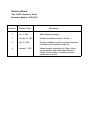
Revision Record
Title: QCR-Z Operator's Guide
Document Number: 20-21-2001
Revision
Effective Date
Description
1
July 5, 1989
Initial release for printing.
2
October 23, 1989
Revised specifications listed in Section 1.
3
July 16, 1990
Revised installation section to include description
of buffered and unbuffered mode use.
4
January 2, 1991
Added operator instructions for Chinon 35mm
camera module, and deleted instructions for
Pentax 35mm camera. Complete document
update and re-format.
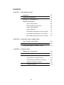
Contents
CHAPTER 1 PRE-INSTALLATION
Inspection
. . . . . . . . . . . . . . . . . . . . . . . . . . . . . . . . 1-2
Unpacking Instructions . . . . . . . . . . . . . . . . . . . . . 1-3
Inventory of Accessory Kit . . . . . . . . . . . . . . . . . . 1-4
Physical Dimensions . . . . . . . . . . . . . . . . . . . . . . . 1-5
Space Requirements
. . . . . . . . . . . . . . . . . . . . . 1-6
Environmental Specifications . . . . . . . . . . . . . . . 1-7
Power Requirements . . . . . . . . . . . . . . . . . . . . . . 1-7
Agency Approvals . . . . . . . . . . . . . . . . . . . . . . . . 1-7
M35 Module Specifications (35mm Camera) . . 1-7
M120 Module Specifications (4x5 Camera) . . . 1-7
M240 Module Specifications (8x10 Camera) . . 1-7
CHAPTER 2 CONTROLS AND CONNECTORS
User Controls and Display . . . . . . . . . . . . . . . . . . 2-2
Status and Error Indicators . . . . . . . . . . . . . . . . . . 2-3
Power and Signal Connector Panel . . . . . . . . . . . 2-5
CHAPTER 3 INSTALLATION
Making the Connections . . . . . . . . . . . . . . . . . . . . 3-2
Power Line . . . . . . . . . . . . . . . . . . . . . . . . . . . . . . 3-2
Checking the Line Voltage (120/220VAC)
3-3
Connecting the Interface Cable . . . . . . . . . . . . . 3-4
Programming the GPIB Device Address . . . . . . 3-5
Setting the GPIB DIP Switches . . . . . . . . . . . . . . 3-5
Computer Interface . . . . . . . . . . . . . . . . . . . . . . . 3-8
iv
Contents, continued
CHAPTER 4 OPERATOR'S INSTRUCTIONS
Warm Up Sequence . . . . . . . . . . . . . . . . . . . . . . . 4-2
Handling the Film Modules . . . . . . . . . . . . . . . . . . 4-3
Removing the M35 Module . . . . . . . . . . . . . . . . 4-3
Inserting the M35 Module . . . . . . . . . . . . . . . . . . 4-4
Loading Film Into the 35mm Camera . . . . . . . . 4-5
Unloading 35mm Film . . . . . . . . . . . . . . . . . . . . . 4-7
The M1 20 Module . . . . . . . . . . . . . . . . . . . . . . . . 4-8
Removing the M120 Module . . . . . . . . . . . . . . . 4-8
Inserting the M120 Module . . . . . . . . . . . . . . . . . 4-9
Loading Film Into the M120 Module . . . . . . . . . 4-10
The M240 Module . . . . . . . . . . . . . . . . . . . . . . . . 4-11
Removing the M240 Module . . . . . . . . . . . . . . . 4-11
Inserting the M120 Module . . . . . . . . . . . . . . . . . 4-12
Loading Film Into the M240 Module . . . . . . . . . 4-13
Recording Internal Test Patterns . . . . . . . . . . . . . 4-14
Test Pattern Descriptions . . . . . . . . . . . . . . . . . . 4-14
Imaging Test Pattern 0 . . . . . . . . . . . . . . . . . . . . 4-16
Imaging Test Pattern 1 . . . . . . . . . . . . . . . . . . . . 4-16
Error and Fault Codes . . . . . . . . . . . . . . . . . . . . . 4-17
CHAPTER 5 ADDENDUM
System
Overview . . . . . . . . . . . . . . . . . . . . . . . . . 5-2
Data Structures
. . . . . . . . . . . . . . . . . . . . . . . . . . . 5-4
Pixel Mode Data . . . . . . . . . . . . . . . . . . . . . . . . . 5-4
Run Length Encoded Data . . . . . . . . . . . . . . . . . 5-4
Black Jumping . . . . . . . . . . . . . . . . . . . . . . . . . . . 5-5
Color Film Compensation . . . . . . . . . . . . . . . . . . . 5-5
Brightness Levels
. . . . . . . . . . . . . . . . . . . . . . . . 5-5
Lookup Tables . . . . . . . . . . . . . . . . . . . . . . . . . . . 5-7
Custom Brightness Levels
and Lookup Tables . . . . . . . . . . . . . . . . . . . . . . . 5-9
V
1
Pre-lnstallation
This chapter contains important information concerning the
QCR-Z's power, space, and environmental requirements. Read
this section carefully and determine whether your site meets all
of these requirements before you attempt to install the film
recorder.
Chapter 1 gives additional instructions on
•
Inspecting the packaging for shipping damage
•
Unpacking your new Agfa Matrix film recorder
•
Checking that the accessory kit is complete
1-1
QCR-Z Operator's Guide Version 4
Pre-lnstallation
INSPECTION
Upon arrival, inventory the shipment with the carrier's driver.
•
Carefully inspect the packing material for obvious signs of damage
such as crushed, punctured, torn, broken, wet or rattling packages.
•
If damage is not evident, sign and stamp a bill of lading "condition
of contents unknown - subject to inspection".
•
If damage is evident, contact your Purchasing Department for action,
have the carrier's driver indicate the damage on the freight bill, and
sign all copies of the bill.
During formal inspection, you should:
•
Open all packages within 15 days of receipt for a complete inspection of the consignment.
•
Report concealed damage to the carrier within 15 days of receipt or
the carrier may not accept liability.
PACKING LIST
Figure 1-1. Receiving Inspection
QCR-Z Operator's Guide Version 4
1-2
Pre-lnstallation
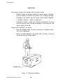
UNPACKING INSTRUCTIONS
The film recorder and its accessories are shipped in a single carton, while the
camera modules are shipped separately. To unpack the unit:
•
Remove the carton staples from the top of the box by prying them up
with a regular screwdriver.
•
Remove the foam plate covering the unit. It is wrapped in blue plastic
and lays across the entire machine. This exposes the unit and its
accessory kit which is packaged separately.
•
Take out the accessory kit and set it in a safe place.
•
Carefully lift the video imager from the carton and place it on a flat,
secure surface. The unit is heavy, so have another person assist you.
•
Save all shipping materials in case the unit requires additional
transportation.
FIND ENCLOSED
ACCESSORIES
REMOVE ALL
PACKING STAPLES
LIFT UNIT OUT OF
AND PLACE ON A
SECURE SURFACE
Figure 1-2. Unpacking the Film Recorder
1-3
QCR-Z Operator's Guide Version 4
Pre-lnstallation
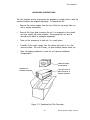
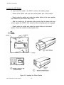
INVENTORY OF ACCESSORY KIT
The following is a list of standard accessory kit components, and is for your
reference only. Your kit may be different depending on specific order requests or
customer requirements. The packing list attached to the shipping carton lists the
exact contents of your accessory kit. Figure 1-3 will help you identify each
component.
Item
Quantity
Description
A
1
Power cord
B
1
Operator's Guide (this manual)
C
1
Factory test films
Figure 1-3. Accessory Kit Components
QCR-Z Operator's Guide Version 4
1-4
Pre-lnstallation
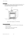
PHYSICAL DIMENSIONS
The unit weighs approximately 84 pounds (38kg).
Note:
These dimensions do not include the camera module.
Figure 1-4. Cabinet Dimensions
1-5
QCR-Z Operator's Guide Version 4
Pre-lnstallation
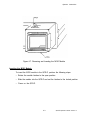
SPACE REQUIREMENTS
The QCR-Z can be positioned on a table or sturdy shelf in a space only slightly
larger than the outer dimensions of the cabinet itself. However, for servicing the unit
you should provide an area of at least 20 square feet (48" x 60") for service
access. This enables you to lay the unit on its base, remove the top cover, and
access the interior of the system from all four sides.
You must keep clear an area of at least 36 inches (915mm) at the front side of the
unit to access the user controls and use the camera modules. You should also
allow an additional six inches of free space at the back of the unit for the GPIB and
power cables. Refer to Figure 1-5. below for the recommended user and service
clearances.
Figure 1-5. Space Requirements for User and Service Access
QCR-Z Operator's Guide Version 4
1-6
Pre-lnstallation
ENVIRONMENTAL SPECIFICATIONS
You should install the film recorder in a location where the operating conditions are
within the limits specified below.
Conditions
Temperature
Operating
+15° C to +30° C
(+59° F to 86° F)
35% - 65%
0° C to +70° C
(+32° F to +158 ° F)
20% to 70%
non-condensing
Storage
Humidity
non-condensing
POWER REQUIREMENTS
Ensure that adequate AC input power is available. The unit's power requirements
are stated on the serial number identifying label located on its rear panel. Ideally,
the film recorder should have its own 20 amp individual circuit with a common
system safety ground.
Power Input
3 wire
(safety ground)
single phase.
Voltages
100, 120
220, or 240
Volts AC
Frequency
47 Hz to 63 Hz
Voltage
Variations
+/- 10% of
rated voltage
Fusings
100 -120 VAC: 1.5 AMP
Slo-Blo
220 -240 VAC: 1.0 AMP
Slo-Blo
AGENCY APPROVALS
All units will meet F.C.C. specifications according to CFR 47. Docket 20780 part 15
subchapter J for class A operation with respect to EMI/RFI emissions.
1-7
QCR-Z Operator's Guide Version 4
Pre-lnstallation
M35 Module Specifications (35mm Camera)
A.
B.
C.
D.
E.
F.
G.
H.
35mm cassettes
36 frames
>100 ASA / 21 DIN
Daylight
36mm
24mm
+/- 1%
57 pixels/mm in 2K mode
114 pixels/mm in 4K mode
Format:
Roll Length:
Sensitivity:
Color Balance:
Image Dimension (Horiz):
Image Dimension (Vertical):
Tolerance:
Scaling Factor (Horiz/Vert):
M120 Module Specifications ( 4 x 5 Camera)
A.
B.
C.
D.
E.
F.
G.
H.
4x5 sheet film
Polaroid 559
Format:
Recommended Medium:
Sensitivity:
Color Balance:
Image Dimension (Horiz):
Image Dimension (Vertical):
Tolerance:
Scaling Factor (Horiz/Vert):
>100 ASA / 21 DIN
Daylight
120mm
90mm
+/- 5%
17 pixels/mm in 2K mode
34 pixels/mm in 4K mode
M240 Module Specifications ( 8 x 1 0 Camera)
A.
B.
C.
D.
E.
F.
G.
H.
8x10 sheet film
Polaroid 809
>100 ASA / 21 DIN
Daylight
246mm
185mm
+/- 5%
17 pixels/mm in 4K mode (2K not supported)
Format:
Recommended Medium:
Sensitivity:
Color Balance:
Image Dimension (Horiz):
Image Dimension (Vertical):
Tolerance:
Scaling Factor (Horiz/Vert):
QCR-Z Operator's Guide Version 4
1-8
2
Controls and Connectors
Chapter 2 describes the front panel user controls and rear panel
electrical connectors. Here you will find a description of each
switch and connector and its related function to the QCR-Z film
recorder. Use this chapter as a reference section to Chapter
3- Installation, and Chapter 4- Operator's Instructions.
2-1
QCR-Z Operator's Guide Version 4
Controls and Connectors
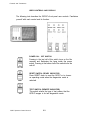
USER CONTROLS AND DISPLAY
The following text describes the QCR-Z's front panel user controls. Familiarize
yourself with each control and its function.
POWER ON - OFF SWITCH
Pressing in the top half of this switch turns on the film
recorder and illuminates the lamp inside the power
switch. Pressing in the bottom half of the switch turns the
unit off.
RESET SWITCH (READY INDICATOR)
Press RESET down to reset the QCR-Z or to choose
an operating mode when the diagnostics mode is
selected.
TEST SWITCH (REMOTE INDICATOR)
This switch selects the type of test pattern that the
QCR-Z images in its test diagnostics mode.
QCR-Z Operator's Guide Version 4
2-2
Controls and Connectors
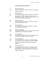
STATUS AND ERROR INDICATORS
RECORD
RECORD INDICATOR
This indicator illuminates while the QCR-Z is recording an
image onto the film.
RED
GREEN
RED INDICATOR
This indicator illuminates while the QCR-Z is recording red
image data onto the film. If there is a fault or error, a
combination of the RED, GREEN, and BLUE indicators may
be on, telling you what the problem is.
GREEN INDICATOR
This indicator illuminates while the QCR-Z is recording
green image data onto the film.
BLUE
BLUE INDICATOR
This indicator illuminates while the QCR-Z is recording
blue image data onto the film.
MODULE
MODULE INDICATOR
This indicator illuminates if there is a fault with the camera
module that you are using on the QCR-Z.
FILM
FILM INDICATOR
This indicator illuminates when the 35mm module reaches
the end of film and the last frame is exposed.
FAULT
FAULT INDICATOR
This indicator illuminates if there is a hardware problem
with the QCR-Z. Some combination of the RED, GREEN,
and BLUE indicators will be lit, telling you where the
problem is.
ERROR
ERROR INDICATOR
This indicator illuminates if there is a software problem
with the QCR-Z or the host. Some combination of the
RED, GREEN, and BLUE indicators will be lit, telling you
where the problem is.
2-3
QCR-Z Operator's Guide Version 4
Controls and Connectors
STATUS AND ERROR INDICATORS (CONTINUED)
POWER ON - OFF INDICATOR
This indicator is lit while the QCR-Z is powered on.
READY INDICATOR
This indicator illuminates when the QCR-Z is ready to
record an image.
REMOTE INDICATOR
This indicator illuminates while the QCR-Z is receiving
image data from the host computer.
QCR-Z Operator's Guide Version 4
2-4
Controls and Connectors
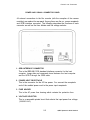
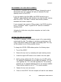
POWER AND SIGNAL CONNECTOR PANEL
All external connections to the film recorder (with the exception of the camera
modules) are made at its rear panel. Among these are the a.c. power receptacle
and GPIB interface connector. The following describes the functions of each
connector as well as the fuse holders and line voltage selector.
1. GPIB INTERFACE CONNECTOR
This is the IEEE-488 1978 standard interface connector for the host
computer. Image data and commands travel between the host computer
and the QCR-Z through the GPIB cable.
2. POWER INPUT RECEPTACLE
This is the connector for the AC line power. You connect the receptacle
end of the molded power cord to the power input receptacle.
3. FUSE HOLDER
This is the AC power fuse housing which contains the protective fuse.
4. VOLTAGE SELECTOR
This is a removable printed circuit that selects the input power line voltage
(120/220 VAC).
2-5
QCR-Z Operator's Guide Version 4
Controls and Connectors
This page is intentionally left blank.
QCR-Z Operator's Guide Version 4
2-6
3
Installation
Chapter 3 instructs you on how to properly install the QCR-Z film
recorder. You should install the unit in a location which meets
the power, space, and environmental requirements given in
Chapter 1. Before installing the QCR-Z, familiarize yourself with
the function and operation of each control and connector
described in Chapter 2.
Chapter 3 gives instructions on
• Making the connections to hook up the power cord, selecting
the proper line voltage, and connecting the GPIB cable.
• Programming the GPIB device address.
If you encounter a problem during the installation of this
equipment, contact the nearest Agfa Matrix service location
immediately. Use the toll free telephone hotline if you are in
the Continental United States. This telephone number is:
1-800-456-2600
3-1
QCR-Z Operator's Guide Version 4
Installation
MAKING THE CONNECTIONS
POWER LINE
• Ensure that the POWER switch is in the OFF position. This switch is
located on the film recorder's front panel, and is off when the bottom half ('0')
is pressed in.
•
Check the film recorder's a.c. line voltage requirements by inspecting
the serial number tag, located on its rear panel. They must exactly match
the line power that your wall outlet provides.
Check the serial number tag
and make sure the line voltage
requirements are met.
•
Connect the molded end of the power cord (included in the
accessory kit) to the a.c. receptacle on the QCR-Z's rear panel. Connect
the three-prong end to a power line outlet sharing a common ground with
the unit or a wall outlet having a common ground.
WARNING
If you are uncertain whether you have the correct power for the unit,
contact a licensed electrician or qualified service engineer. Never use a
3-to-2 prong a.c. adapter or otherwise defeat the ground prong on the
power cord provided with the unit.
QCR-Z Operator's Guide Version 4
3-2
Installation
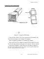
CHECKING THE LINE VOLTAGE (120/220 VAC)
There is a line voltage selector card inside the power input module that houses
the AC receptacle and the line fuse. This selector card is positioned just below
the fuse and is inserted in such a way that allows you to select 120 or 220 volt
operation. If you change the line voltage from 120 volt to 220 volt operation, be
certain to change the fuse to the proper rating for the new line voltage. The
fuse values are provided in Chapter 1 of this manual.
•
Ensure that the POWER switch is in the OFF position, and that the power
cord is removed from the receptacle on the back of the QCR-Z.
•
Slide the clear plastic safety cover to the left, exposing the voltage
selector board. The selected voltage is written on the card and should be
clearly visible to you.
• To change the voltage, carefully remove the selector card with a pair of
needle nose pliers, turn it 180 degrees, and re-insert it.
120 VOLT SELECTION
220 VOLT SELECTION
Figure 3-1. Input Power Selection
3-3
QCR-Z Operator's Guide Version 4
Installation
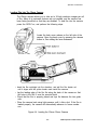
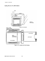
CONNECTING THE INTERFACE CABLE
The GPIB cable provides the link that allows the QCR-Z and the host computer
to communicate with each other. Plug the 24 pin GPIB cable (supplied by the
host computer) into the connector on the back of the QCR-Z. Secure the
connector in pace by tightening the screws on either side of the connector.
It is possible that you may have to modify or configure the GPIB board inside
the host computer in order to ensure that it can communicate with the QCR-Z.
Consult your Agfa Matrix dealer if you need assistance with setting up the
host's GPIB board.
Figure 3-2. Interface Cable Connection
QCR-Z Operator's Guide Version 4
3-4
Installation
PROGRAMMING THE GPIB DEVICE ADDRESS
The QCR-Z is compatible with most PC systems. Knowing the rate of
data transfer from your computer will help you determine the best
operating mode for the QCR-Z.
If your bus speed is less than 8Mhz, the QCR-Z should be set to
"buffered" mode. Buffered mode activates a two scan line (8K) memory
within the QCR-Z. This helps to minimize data transfer problems
associated with slower computers.
If your computer's bus speed is 8 Mhz or higher, the QCR-Z should be
set to "un-buffered" mode. A typical PC-AT uses the un-buffered
operating mode.
Activating the buffer when using faster computers can lead to data
transfer errors.
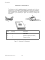
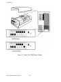
SETTING THE GPIB DIP SWITCHES
The QCR-Z is assigned a GPIB address as part of its communication
protocol with the host. The address is set during manufacturing to 02
using a DIP switch located on the inside of the display panel. You may
set the address to one of thirty possible choices.
To change the QCR-Z's GPIB address perform the following steps:
1.
Turn off the QCR-Z.
2.
Remove the top cover by unscrewing the eight mounting screws.
3.
Locate the eight bit DIP switch on the inside of the front panel.
4.
Set the primary address bits A5 to A2 (8 to 5 on the DIP switch).
The address bit designations are per IEEE 488 standard. A5 is the
most significant bit, A1 is the least significant bit. The remaining
switches are for extended addressing that is not currently available.
These switches should be set to "1" for normal operation.
5.
Replace the top cover and screws.
6.
Power on the QCR-Z. The host computer will read the new address.
3-5
QCR-Z Operator's Guide Version 4
Installation
Figure 3-3. Setting The GPIB Device Address
QCR-Z Operator's Guide Version 4
3-6
4
Operator's Instructions
Chapter 4 instructs you on routine operating procedures
including:
•
•
•
Powering the film recorder on and observing its warm up
and self test routines
Loading and unloading the camera modules
Interpreting status and error messages, and taking
corrective action if you have a problem.
4-1
OCR-7 Operator's Guide Version 4
Operator Instructions
WARM UP SEQUENCE
IMPORTANT
Allow the QCR-Z to warm up for at least 20 minutes before you begin imaging.
The QCR-Z's front panel LED indicators will begin flashing after you turn the unit
on. The QCR-Z will perform internal intensity calibrations for red, green and blue
according to the type film module you are using. Once the system has calibrated
properly, the LED indicators will blank and the READY LED will illuminate.
Figure 4-1. Warm Up Sequence
QCR-Z Operator's Guide Version 4
4-2
Operator Instructions
HANDLING THE FILM MODULES
The M35 Module
To prevent dust build-up on the face of the QCR-Z's CRT, you should leave a
camera module installed in the unit at all times.
Removing the M35 Module
To remove the M35 module from the QCR-Z, perform the following steps:
• Power off the QCR-Z and open the smoked plastic door of the module.
• Reach inside the module and rotate the module latches to the open position
(the handles will point toward each other).
• Pull the ejector tab at the top and center of the module's front opening to
dislodge the module. Slide the module out of the enclosure while ensuring that
the ejector tab does not jam against the QCR-Z.
• Close the smoked plastic door once the module has been removed.
Figure 4-2. Removing the 35mm Module
4-3
QCR-Z Operator's Guide Version 4
Operator Instructions
Inserting the M35 Module
To insert the M35 module in the QCR-Z, perform the following steps:
• Power off the QCR-Z and open the smoked plastic door of the module.
• Reach inside the module and rotate the module latches to the open position
(the handles will point toward each other).
• Slide the module into the enclosure while ensuring that the ejector tab does
not jam against the QCR-Z. Also check that the two guiding pins are engaged.
• Reach inside the module and rotate the module latches to the locked
position. Close the module's smoked plastic door.
Figure 4-3. Inserting the 35mm Module
QCR-Z Operator's Guide Version 4
4-4
Operator Instructions
Loading Film Into The 35mm Camera
The Chinon camera allows you to take up to 36 high resolution images per roll
of film. Many of its automatic features are not needed, and the camera has
been factory-modified so that they are disabled. To load film into the camera,
power the QCR-Z on, and perform the following steps:
Locate the back cover release on the left side of the
camera. Open the back cover by pressing the release
button in, then sliding the lever downward.
• Insert the film cartridge into the chamber, and pull the film leader out
until it aligns with the yellow leader mark inside the camera.
• Lay the leading edge of the film flat along the back of the camera so that
the holes in the film fit over the sprocket teeth.
• Check that the film is properly placed and lays flat between the two guide
rails.
• Close the camera back using light pressure until it clicks shut. If the film is
loaded properly, the camera will automatically advance to frame number
one.
Figure 4-4. Loading the Chinon 35mm Camera
4-5
QCR-Z Operator's Guide Version 4
Operator Instructions
Loading Film Into The 35mm Camera (continued)
Send the load film command from the host to ready the QCR-Z for imaging.
* The load film command will:
Advance the film.
Reset the Frame counter to 1.
Clear the end of film condition.
You can use the QCR-Z's front panel controls to initiate a load film sequence.
To do this, push the TEST button up on the front panel until the unit beeps
three times.
QCR-Z Operator's Guide Version 4
4-6
Operator Instructions
Unloading 35mm Film
When the film advances past the last frame, the Error indicator is lit, and you
should now unload the film in the following way:
• Locate the film rewind button on the
under side of the camera.
• Slide the rewind button's protective
cover in the direction of the arrow to
provide access to the rewind button.
• Press the rewind button to rewind
the film.
• Remove the film from the camera
only after it is fully rewound and the
motor stops.
Slide protective cover
in direction of arrow
then press
Film Rewind Button
Locate the back cover release on the left side of the
camera. Open the back cover by pressing the release
button in, then sliding the lever downward. Remove the
film from the chamber.
Push button in
Slide lever downward
Figure 4-5. Unloading Film from the Chinon Camera
Send the unload film command from the host or use the QCR-Z's front panel
controls to initiate an unload film sequence. To do this, push the TEST button
down on the front panel until the unit beeps three times.
4-7
QCR-Z Operator's Guide Version 4
Operator Instructions
The M120 Module
The M120 module is designed to handle 4x5 Polaroid 559 instant print film. The
M120 module utilizes the industry standard Graflex film holder and will also
accommodate 4x5 sheet film using Lisco cassettes.
LATCH
FILM HOLDER
CLASP
FILM HOLDER
CLASP —
LATCH
Figure 4-6. Major Components of the M120 Module
Removing the M120 Module
To remove the M120 module from the QCR-Z, perform the following steps:
• Power off the QCR-Z.
• Rotate the module latches to the open position.
• Slide the module out of the QCR-Z.
QCR-Z Operator's Guide Version 4
4-8
Operator Instructions
Figure 4-7. Removing and Inserting the M120 Module
Inserting the M120 Module
To insert the M120 module in the QCR-Z, perform the following steps:
• Rotate the module latches to the open position.
• Slide the module into the QCR-Z and set the latches to the locked position.
•
Power on the QCR-Z.
4-9
QCR-Z Operator's Guide Version 4
Operator Instructions
Loading Film Into The M120 Module
QCR-Z Operator's Guide Version 4
4-10
Operator Instructions
The M240 Module
The M240 module handles 8x10 Polaroid 809 instant print film. It uses the
industry standard 8x10 film holder and will accommodate 8x10 sheet film using
Lisco cassettes.
The QCR-Z automatically defaults to the 4K mode when you install the M240
module.
Figure 4-9. Major Components of the M240 Module
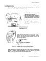
Removing the M240 Module
To remove the M240 module from the QCR-Z, perform the following steps:
•
Power off the QCR-Z.
• Rotate the module latches to the open position.
• Slide the module out of the QCR-Z.
4-11
QCR-Z Operator's Guide Version 4
Operator Instructions
Figure 4-10. Removing and Inserting the M240 Module
Inserting the M240 Module
To insert the M240 module in the QCR-Z, perform the following steps:
• Rotate the module latches to the open position.
• Slide the module into the QCR-Z and set the latches to the locked position.
• Power on the QCR-Z.
QCR-Z Operator's Guide Version 4
4-12
Operator Instructions
Loading Film Into The M240 Module
CASSETTE
RELEASES.
DARKSLIDE
FILM
TAB
SLIDE THE 8 X 1 0 FILM
CASSETTE INTO SLOT
FILM
LIP
Figure 4-11. Loading the M240 Module
• Position the film cassette so that it lays horizontally with the darkslide to the
left and with the releases at the top edge of the magazine.
• Open the cassette by pressing on the releases and unfolding.
• Place the 809 film into the cassette by placing the film lip under the film tab.
The film should align between the blue lines on the cassette. Close the cassette.
• Ensure that the darkslide is closed. Remove the film sleeve by pulling the
film from the side marked with the three arrows. Try not to pull the sleeve from
the side, this may cause the film to skew.
4-13
QCR-Z Operator's Guide Version 4
Operator Instructions
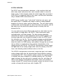
RECORDING INTERNAL TEST PATTERNS
The QCR-Z provides internal test and diagnostic functions which allow you to
expose a test image onto film and determine whether or not the system is
working properly. You should image the internal test pattern only after you turn
the QCR-Z on, and allow the system to warm up for at least twenty minutes.
Upon power up the QCR-Z does the following:
• It loads internal default brightness tables and the corresponding color
look-up tables for each of the red, green and blue scans.
• It looks at the type of camera module that is installed, and determines the
proper image size for the test pattern that you will expose onto the film. The
QCR-Z will image the test patterns in the 2K mode for the M35 and M120
modules, and in the 4K mode for the M240 module.
• It calibrates to the brightness values stored in its internal look-up tables.
IMPORTANT
The QCR-Z must not be actively controlled by the host computer during the
time that you are recording internal test patterns. Externally loaded look-up
tables may cause an imbalance in the colors on the internal test patterns.
This is why you image the internal test patterns after a power on and
warmup cycle. As an added precaution, you may disconnect the IEEE-488
interface connector from the back of the QCR-Z, and reset the film recorder
prior to running internal test patterns.
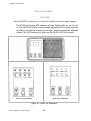
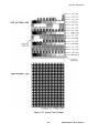
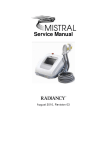
Test Pattern Descriptions
The QCR-Z can generate two different test patterns in the local mode. These
patterns are illustrated in Figure 4-12.
Test pattern 0 verifies focus, geometric and radiometric registration, color
registration, and color balance. It appears as a set of sixteen horizontal bars,
four each of the three colors, and four in neutral. In each color area, three
color bars contain alternating smaller bars of colored and dark pixels, and the
other bar shows a scale of color intensity.
Test pattern 1 verifies linearity, focus, density, and color registration. It appears
as a uniform field of neutral color, sixteen pixel squares on a dark background.
The neutral color squares in this image are produced from the combination of
the three color passes.
QCR-Z Operator's Guide Version 4
4-14
Operator Instructions
Figure 4-12. Internal Test Patterns
4-15
QCR-Z Operator's Guide Version 4
Operator Instructions
Imaging Test Pattern 0
Load film into the camera module and prepare the module for an exposure
(advance film to frame #1, remove dark slide, etc.) To select test pattern 0,
press and hold the TEST switch down so that you hear the QCR-Z's audio
alarm beep twice. When this occurs, the QCR-Z will image test pattern 0 onto
the film.
If you wish to view the the test pattern as it scans on the QCR-Z's CRT,
power off the QCR-Z and remove the module. Power the film recorder on and
wait for its warmup routine to finish. Press the TEST switch down so that you
hear the QCR-Z's audio alarm beep once, then release the TEST switch. The
QCR-Z will not care whether the camera module is installed, and it will begin
scanning the test pattern line-by-line on the CRT. If you hold the TEST switch
down for two beeps with no module installed, the QCR-Z will indicate a module
fault and terminate the test sequence.
Imaging Test Pattern 1
To select test pattern 1, press and hold the TEST switch up so that you hear
the QCR-Z's audio alarm beep twice. When this occurs, the QCR-Z will image
test pattern 1 onto the film. The same conditions apply as for test pattern 0; if
you wish to view the test pattern on the CRT, press the TEST switch up so that
you hear the QCR-Z's audio alarm beep once.
QCR-Z Operator's Guide Version 4
4-16
Operator Instructions
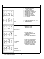
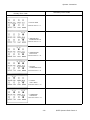
ERROR AND FAULT CODES
The QCR-Z uses its front panel LED array for reporting errors and faults. If you
are using the Matrix MVP card in the host computer, the error messages will be
also be displayed in Hexadecimal on the Foreground screen message window.
The QCR-Z provides additional error information through secondary error
codes. This helps to isolate the source of the problem so that you or a
qualified service engineer can troubleshoot it more effectively. Pressing the
RESET switch down after an error occurs will display secondary error codes in
the QCR-Z's LED array. The top four LEDs (RECORD - BLUE) serve as the
most significant bit, while the bottom four LEDs (MODULE - ERROR) serve as
the least significant bit. The contents of the QCR-Z's internal registers can be
obtained by pressing the TEST switch down then up.
4-17
QCR-Z Operator's Guide Version 4
Operator Instructions
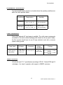
Secondary Error Codes
Primary Error Code
00
LUT checksum Failure
01
Internal ROM checksum failure
02
Internal ROM checksum failure
03
RAM failure during bit set/reset test
04
RAM failure during all values test
05
RAM failure during mux test
- geometry correction
= MEMORY
FAULT
COMPUTER DISPLAY = 91
= GPIB INTERFACE
FAULT
06
RAM failure during A55A test
07
RAM failure during REFRESH test
08
LUT RAM failure
00
Unable to put interface into LOCAL mode
01
GPIB handshake error.
00
Beam intensity too high
01
Beam intensity too low
00
No module detected for an
01
Invalid module ID
02
Film Jam error (bulk cameras only)
00
Unable to find neutral filter position
COMPUTER DISPLAY = 92
= CRT BEAM
CALIBRATION FAULT
COMPUTER DISPLAY = 93
operation that requires a module
= MODULE
FAULT
COMPUTER DISPLAY = A1
01
Wrong number of filter positions
= FILTER WHEEL
FAULT
02
Unexpectedly found no filter position
03
Unexpectedly found no filter position
COMPUTER DISPLAY = A2
04
Maximum step count exceeded in
searching for next filter position.
= UNIMPLEMENTED
FUNCTION
COMPUTER DISPLAY = 86
OCR-Z Operator's Guide Version 4
4-18
Operator Instructions
Secondary Error Codes
Primary Error Code
= OUT OF FILM
COMPUTER DISPLAY = 01
= UNEXPECTED
COMMAND BYTE
COMPUTER DISPLAY = 81
= UNEXPECTED
DATA BYTE
COMPUTER DISPLAY = 82
= ILLEGAL
COMMAND BYTE
COMPUTER DISPLAY = 83
= ILLEGAL
DATA BYTE
COMPUTER DISPLAY = 84
= COMMAND
INTERRUPT
COMPUTER DISPLAY = 85
4-19
QCR-Z Operator's Guide Version 4
Operator Instructions
This page is intentionally left blank.
QCR-Z Operator's Guide Version 4
4-20
5
Addendum
This chapter contains a system overview of the QCR-Z that
describes its basic operating principles. It may contain additional
information that is added at the time the manual is shipped from
the Publications Department.
5-1
QCR-Z Operator's Guide Version 4
Addendum
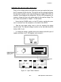
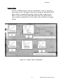
SYSTEM OVERVIEW
The QCR-Z uses microprocessor electronics, a high resolution black and
white video monitor and picture tube, and a camera module to record an
image on film. A host computer creates the actual image data, and sends it
to the QCR-Z in component blocks of red, green, and blue pixel information
using a standard GPIB communication link.
QCR-Z camera modules use a "color wheel" which has red, green, and
blue optical filters. A complete color image is made by making separate
exposures for the red, green, and blue image data. The color wheel rotates
a different filter into the light path for each of the three color passes, and the
light output from the picture tube passes through a focusing lens and
exposes the film.
You may select among three different data structures which define how the
host transfers its image data to the QCR-Z. These include pixel mode,
run-length-coding, and black jumping. The data structure essentially
determines the amount of data compression that the QCR-Z applies to the
incoming image data, and ultimately the speed at which the QCR-Z prints
the information onto the film. The host computer assigns an eight-bit binary
value to each piece of image data it sends the the QCR-Z. The QCR-Z
stores this value in its RAM memory, and modifies it through the use of color
look up tables to compensate for the non-linear characteristics of the
imaging process and the film. The QCR-Z's microprocessor circuits convert
the digital data into an analog voltage which varies the intensity of the CRT
beam, and ultimately produces different colors on the film.
The QCR-Z's microprocessor counts each image data point, and creates
analog voltages which drive the horizontal and vertical deflection windings
surrounding the CRT. Since resolution quality is critical, the scanning speed
is relatively slow when compared to a standard television set. The slower
speed increases the time each pixel is exposed to the film, and allows the
QCR to use relatively low brightness and contrast. This in turn provides a
sharply focused CRT electron beam and greatly reduces the amount of pixel
overlap or fringing that would occur with a brighter CRT.
QCR-Z Operator's Guide Version 4
5-2
Addendum
Figure A-1. Major Components of the QCR-Z
5-3
QCR-Z Operator's Guide Version 4
Addendum
DATA STRUCTURES
Data structures can be defined through software commands to the QCR-Z.
You should have a basic understanding these modes how they affect the
way the QCR-Z scans an image.
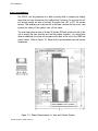
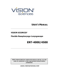
Pixel Mode Data
The QCR-Z requires pixel data for each addressable location where its CRT
can display information. If you create images with large amounts of
information and detail, the corresponding image data file will be very large.
Pixel mode is the data structure that sends image data pixel by pixel to the
QCR-Z. An example of the amount of data that would be required for a 4K,
35mm pixel mode image is as follows:
EACH LINE REQUIRES 4096
BYTES OF PIXEL DATA. IF A 35MM
CAMERA OPTION IS USED, 2732
LINES WILL BE PRODUCED FOR
EACH COLOR PASS.
4096 X 2732 = 11,190,272 BYTES
X 3 PASSES = 33,570,816 BYTES
A SINGLE IMAGE WOULD CONTAIN OVER 33 MEGABYTES OF INFORMATION!
Figure A-2. Pixel Mode Data Requirements
Operating The QCR-Z in the 2K mode would decrease the amount of data
by one-half, thereby decreasing the total imaging time, but the image would
also suffer a corresponding loss in detail.
Run Length Encoded Data
Run length encoding is a form of data compression. Groups of pixels can
be defined as segments to reduce the number of data transfers for a given
scan line. RLC can achieve a data compression factor of 90 to 1 or greater.
Simple images such as bar graphs do not require the high resolution detail
that fine art images require, and are ideal for using RLC.
QCR-Z Operator's Guide Version 4
5-4
Addendum
Black Jumping
Black jumping is an enhanced form of RLC that decreases the actual
imaging time. When an area of an image does not have contrasted data, the
QCR-Z will "jump" over this area and resume scanning at the next
contrasted pixel position. The more areas that are blank, the greater the
time saving during the imaging process.
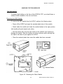
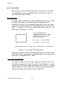
COLOR FILM COMPENSATION
That the image quality and color balance will vary significantly between the
image that you see on a viewing terminal the final image you view on film.
In order to produce an image on film that will accurately display the desired
color shading, compensation for the film must be provided. Each color pass
must be compensated for the relative sensitivity to red, green and blue light.
This means that the average intensity for a red pass will differ from a green
pass versus a blue pass. The average intensity selection for each color
pass will be adjusted through the use of brightness levels.
The film's sensitivity to shades of color or "gamma response" is also
non-linear. The QCR-Z modifies the pixel intensity data to compensate for
the film's gamma response. This is performed through the use of color
lookup tables.
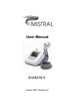
Brightness Levels
Brightness levels are software selectable and are determined by the imaging
mode and the camera module that you are using. A 4K image requires a
lower brightness level than the same image in the 2K mode. The QCR-Z
supports nine different brightness levels to accommodate the various camera
modules. The QCR-Z's CRT scans the red image data at the highest
intensity. This is due to the fact the the film's red emulsion is the first layer
of the color film, and light must pass through the blue and green emlusions
to reach it. The average intensity for green pass is less than the red pass.
The average intensity for the blue pass is the lowest of all.
5-5
QCR-Z Operator's Guide Version 4
Addendum
LIGHT FROM CRT
— COLOR FILTER
LENS
BLUE EMULSION
• BLUE LIGHT ABSORBING FILTER
GREEN EMULSION
GREEN LIGHT ABSORBING FILTER
RED EMULSION
FILM BASE
Figure A-3. Color Film Emulsion Layers
The QCR-Z determines the appropriate brightness levels soon after you
power it on. It reads the type of camera module that you are using, and
loads the brightness levels into memory. If you power the film recorder on
and no camera module is attached, the QCR-Z defaults to the 35mm
brightness levels.
QCR-Z Operator's Guide Version 4
5-6
Addendum
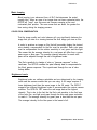
Lookup Tables
The film's GAMMA response must be compensated in order to produce a
linear image on film. The eight bit data for one image line enters the QCR-Z
and is stored in its static RAM memory. When the data is read from the
RAM, it is sent to the lookup table RAM chips where the eight bit data is
color corrected, expanded into a 12 bit output, and converted to an analog
voltage.
Figure A-4. Lookup Table Compensation
5-7
QCR-Z Operator's Guide Version 4
Addendum
Lookup tables consist of three files, one for each color pass. The operating
software PROM chips contain default lookup tables for each of the available
modules. The lookup tables (LUTs) that are written into the PROM are:
1.
2.
3.
4.
Linear LUTs = linear ramp from 0-255 for all three colors.
Polaroid LUTs = properly compensated for Polaroid 559 film.
Kodak LUTs = properly compensated for Kodak Ektachrome 100 film.
Kodak LUTs = properly compensated for Kodak Professional 100 film (4K
mode).
5. Polaroid LUTs = properly compensated for Polaroid 559 film (4K mode).
7. Polaroid LUTs = properly compensated for Polaroid 809 film (4K mode).
The QCR-Z determines the appropriate lookup tables soon after you power it
on. It reads the type of camera module that you are using, and loads the
brightness levels into memory. If you power the film recorder on and no
camera module is attached, the QCR-Z defaults to the 35mm lookup tables.
QCR-Z Operator's Guide Version 4
5-8
Addendum
Custom Brightness Levels and Lookup Tables
The host computer can send commands and data to "customize" the film
recorder's internal brightness and lookup table information. When you do
this, it overwrites the default values and replaces them with the custom
tables that the host computer sends. Keep in mind that the QCR-Z's internal
test patterns have been written to be used with the default LUTs. Using
custom lookup tables may degrade the color quality of the internal test
patterns.
5-9
QCR-Z Operator's Guide Version 4
Addendum
This page is intentionally left blank.
QCR-Z Operator's Guide Version 4
5-10