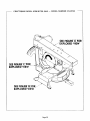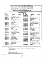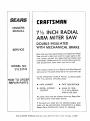
1
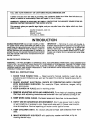
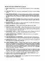
OWNERS
MANUAL
MODEL NO.
315.23/43
Serial
Number
Model
and
serial
number
may be found on plate
motor end cap,
at
You should
record
both
model and serial number in
a safe place for future use.
CAUTION:
Read Rulesfor
Safe Operation
and Instructions
Carefully
SAVE
DOUBLE INSULATED
WITH MECHANICAL
BRAKE
Assembly
Operation
Maintenance
THIS
REFERENCE
q,-,J,4h,, q_'&_S,
71/2 INCH RADIAL
ARM MITER SAW
Introduction
MANUALFOR
FUTURE
CRAFTSMAN _
Repair Parts
ROEBUCK
AND CO., Dept. 698/731A,
Sears Tower,
Chicago,
IL 60684
612547-228
PP,INTEO
IN
U,S,A
FULL ONE YEAR WARRANTY
ON CRAFTSMAN
RADIAL ARM MITER SAW"
If within one year from the date of purchase, this Craftsman Radial Arm Miter Saw falls due to a
defect In matedal or workmanship, Sears will repair It, free of charge,
WARRANTY SERVICE IS AVAILABLE BY SIMPLY CONTACTING
SERVICE CENTER THROUGHOUT
THE UNITED STATES,
THE NEAREST SEARS STORE OR
This warranty gives you specific legal dghts, end you may also have other rights which vary from
state to state.
SEARS ROEBUCK AND CO.
698/731A
SEARS TOWER
CHICAGO, IL 60684
i!
l !!
!
INTRODUCTION
DOUBLE INSULATION Is a concept in safety, In electric power tools, which eliminates the need for the
usual three wlregrounded
power cord and grounded
supply system, Wherever there is electric current in
the tool there are two complete sets of insulation to
protect the user. All exposed metal parts are Isolated
from the Internal metal motor components with protatting insulation.
IMPORTANT
-- Servicing of a tool with double insulation requires extreme care and knowledge of the
system and should be performed only by a qualified
service technician,
For service we suggest you
return the tool to your nearest Sears Store for repair.
Always use original factory replacement parts when
servicing.
RULES FOR SAFE OPERATION
WARNING -- DO NOT ATTEMPT TO OPERATE UNTIL YOU HAVE READ THOROUGHLY AND UNDERSTAND
COMPLETELY ALL INSTRUCTIONS, RULES, ETC. CONTAINED IN THIS MANUAL. FAILURE TO COMPLY CAN
RESULT IN ACCIDENTS
INVOLVING
FIRE, ELECTRIC SHOCK, OR SERIOUS PERSONAL INJURY. SAVE
OWNERS MANUAL AND REVIEW FREQUENTLY FOR CONTINUING
SAFE OPERATION, AND INSTRUCTING
POSSIBLE THIRD.PARTY
USER.
READ ALL INSTRUCTIONS
1. KNOW YOUR POWER TOOL -- Read owner's manual carefully. Learn its applications and limitations as well as the specific potential hazards peculiar to
this tool.
2. GUARD AGAINST ELECTRICAL SHOCK BY PREVENTING BODY CONTACT
WITH GROUNDED SURFACES. For example: Pipes, radiators, ranges, refrigerator enclosures.
KEEP GUARDS IN PLACE and in working order.
.
4. REMOVE ADJUSTING KEYS AND WRENCHES. Form habit of checking to see
that keys and adjusting wrenches are removed from tool before turning it on.
5. KEEP WORK AREA CLEAN. Cluttered areas and benches invite accidents.
J
.
DON'T USE IN DANGEROUS ENVIRONMENT.
Don't use power tool in damp
or wet locations or expose to rain. Keep work area well lit. Never use in explosive atmosphere. Normal sparking of motor could ignite fumes.
KEEP CHILDREN
area.
AWAY. All visitors should be kept safe distance from work
8. MAKE WORKSHOP
KID.PROOF
moving starter keys.
with padlocks,
master
switches,
or by re-
RULES
FoR
SAFE
OPERATION
(Continued)
9. DON'T FORCE TOOL. It will do the job better and safer for which it was designed.
10. USE RIGHT TOOL. Don't force tool or attachment to do a job it was not designed for.
11. WEAR PROPER APPAREL. No loose clothing, gloves, neckties, rings, bracelets,
or other jewelry to get caught in moving parts. Non-slip footwear is recommended. Wear protective hair covering to contain long hair. Roll long sleeves above
elbow.
12. ALWAYS USE SAFETY GLASSES. Also use face or dust mask if cutting oper.
ation is dusty. Everyday glasses only have impact resistant lenses, they are
NOT safety glasses.
i3. SECURE WORK, Use clamps or a vise to hold work. It's safer than using your
hand and it frees both hands to operate tool,
DON'T OVERREACH
-.- Keep proper footing and balance at all times.
MAINTAIN
TOOLS WITH CARE -- Keep tools sharp and clean for best and
safest performance.
Follow
instructions
for lubricating
and changing
accessories. Always
use a clean cloth when cleaning.
Never use brake fluid, gasoline,
or any strong solvents
to clean your tool.
16. DISCONNECT
such
as blades,
TOOLS
-- Before
bits, cutters,
etc.,
17. AVOID UNINTENTIONAL
before plugging in cord.
servicing
and when
changing
all tools should
be disconnected.
STARTING
accessories
-. Make sure switch is in off position
18. USE RECOMMENDED ACCESSORIES -- Consult the owners manual for recommended accessories. The use of improper accessories may cause hazards.
19. NEVER STAND ON TOOL -- Serious injury could occur if the tool is tipped or if
the cutting tool is accidentally contacted.
20. CHECK DAMAGED PARTS -- Before further use of the tool, a guard or other
part that is damaged should be carefully checked to ensure that it will operate
properly and perform its intended function -- check for alignment of moving
parts, binding of moving parts, breakage of parts, mounting, and any other conditions that may affect its operation. A guard or other part that is damaged
should be properly repaired or replaced.
21.
DIRECTION OF FEED .-. When cutting, always pull blade into material from rear
to front of saw. Never push blade into material from front to rear. Wrong feed
direction could result in material kick.back causing serious personal injury.
22. NEVER LEAVE TOOL RUNNING UNATTENDED.
leave tool until it comes to a complete stop.
23. DRUGS, ALCOHOL,
MEDICATION.
drugs, alcohol or any medication.
TURN POWER OFF. Don't
Do not operate
Page 3
tool under the Influence
of
RULES FOR SAFE OPERATION
(Continued)
24. OUTDOOR
USE EXTENSION
CORDS -- When tool is used 6u_do____, use only
extension
cords suitable
for use outdoors,
Outdoor approved
cords are marked
with the suffix W-A, for example
-- SJTW-A or SJOW.A.
25. DON'T-Place either hand in the cutting area when the saw is connected
to the
electrical
power supply, Accidental
starting
could result in serious personal
injury.
26. DON'T -- FORCE CUTTING
ACTION.
Stalling
or partial stalling
of motor can
cause major damage, Allow motor to reach full speed before cutting.
27, DON'T -- Use blades recommended
for operation
at less than 5500 RPM or of a
diameter
not recommended.
The use of improper
blades may cause hazardous
operating
conditions,
28. DON'T -- Attempt
to cut small pieces, Injury could result from improper
control
or clamping
of such material,
29. DON'T -- Wedge anything
against
fan to hold motor shaft, This action will
cause serious damage to the saw motor,
30. DO -- Make certain the blade rotates in the correct direction,
Incorrect
rotation
will cause material
"Kickback"
and possible
serious
injury to operator,
31, DO -- Keep saw blade sharp and properly set to avoid blade cracking
and grabbing, possibly
resulting
in a serious accident,
32. DANGER:
A coasting
cutting
tool can be dangerous,
To avoid possible
serious
injury, apply brake immediately
after completion
of cut,
33. ALWAYS
use identical
replacement
parts when servicing,
34. WEAR EYE PROTECTION.
35. KEEP HANDS OUT OF PATH OF SAW BLADE.
36, DO NOT OPERATE
SAW WITHOUT
GUARDS
IN PLACE.
37. DO NOT PERFORM
ANY OPERATION
FREEHAND.
38. NEVER REACH AROUND
SAW BLADE.
39, SHUT OFF POWER AND WAIT FOR SAW BLADE TO STOP BEFORE SERViC.
ING OR ADJUSTING
TOOL.
40, WARNING:
TO REDUCE THE RISK OF INJURY,
RETURN SAW HEAD TO THE
FULL REAR POSITION
AFTER EACH CROSSCUT
OPERATION,
41, This tool is intended
for residential
use only,
42, SAVE THESE INSTRUCTIONS.
The operation of any miter saw can result in
foreign objects being thrown into the eyes, which
can result in severe eye damage. Always wear
safety goggles complying with ANSI Z87,1 (shown
on Package) before commencing
power tool
or_eration. Safety Goggles are available at Sears
Catalog Order or Retail Stores,
TABLE OF CONTENTS
Unpacking ...................................
Mounting
of Miter Saw ........................
Assembly ...................................
Adjustments ...............................
Operating Instructions
.....................
Table Extension and
5
6
6
7-9
10-11
Securing Workpiece .......................
Typical Operations ........................
Maintenance
.............................
Trouble Shooting ............................
illustration
and Parts List ...................
How to Order Repair Parts ....................
p,,._ _ i_ 4
11.12
12-16
18-21
22
25-31
32
TOOLS
HEEDED
FOR
ASSEMBLY AND ADJUSTMEHT
Your miter saw can be assembled and adjusted with a tow be$1c hand tools shown below:
?/16" AND 1/2" WRENCHES
MEDIUM
BLADE WRENCH
3/i6"
ALLEN WRENCH
(FURNISHED)
SCREWDRIVER
:
(FURNISHED)
PHILLIPS
SCREWI:_VER
CRRFTSMRN
E1',1i I, I'_ i, i ,1i i,'1 ' I, i,i,l'q_
|l,/i,l,,_iii,
8" ADJUSTABLE
WRENCH
,I,ili,
COMBINATION
2. Remove the two hex nuts and washers
miter saw off the cardboard pad.
SQUARE
,-LOCK
Remove the miter saw from the carton by lifting it
by the miter saw table. See Figure 1. CAUTION:
When removing the miter saw do not lift by the
operating
handle or the saw arm as this may
Cause misalignment.
i i'i,l'l_
i_,l_/,lli,l'l,i'ili,l,hl,],l'l
UNPACKING
,
I,iii,i,i
BEVEL
LOCK_
LEVER
BurToN
ATING HAHDLE
and lift the
3, Your miter saw is shipped with the saw head locked both in the rear positron and the 45 ° miter set.
ting. To release the saw head, unlock by turning
the lock lever counter-clockwise,
This will allow
the saw head to move forward for operating pos.
itions, Move the saw head through
its entire
movement,
front to rear. several times to check
for binding, Should saw head bind in its move.
merit, make adjustment
as follows: See Fig. 1
1, Move saw head to futl rear position.
2. Using allen wrench furnished, loosen
screw (A) on front guide rod clamp, one
half turn.
3. Move saw head through its entire move
ment, front to rear several times, stopping
it in the front position,
4, Move the saw head slightly to the rear and tighten
screw (A) securely,
5. Recheck for any binding in saw head
movement.
Should
binding
Still be present
after adjusting,
return the saw to your nearest Sears retail store. See
Page 11 for operating instructions
of miter arm,
Page 5
\
Fig, 1
FASTENING MITER SAW TO WORKBENCH
OR LEG
SET (9.22246)
DISCONNECT
MITER SAW FROM POWER SUPPLY
if the miter saw Is to be used in a permanent location, it should be fastened securely to a firm supporting surface such as a workbench or accessory leg
set (9-22246). It Is recommended
that the saw be
mounted so that the saw table Is approximately 39"
above the floor, However, for your convenience and
safety you might require a different height, in all
cases care must be taken to assure operator vislblllty of cutting area. Holes should be drilled through
supporting surface of the workbench as illustrated
in Figure 2. Each leg of the miter saw should be
bolted securely using 5/16' diameter machine bolts,
5/16" hex nuts, and lock washers. Bolts should be of
sufficient length to accommodate legs of miter saw,
washers, hex nuts, and thickness of supporting surface. Tighten all four bolts securely, if the saw Is to
be used in a portable application, It is recommended
that It be fastened to a mounting board. The board
should be of sufficient size to avoid tipping of saw
while in use. Any good grade of plywood or chip.
board with a 3/4" minimum thickness Is recom.
mended, Mount saw to board using hole pattern as
shown in Figure 2 and described above. Clamp board
securely to workbench.
SECURING WORKBENCH
AND LEGS TO FLOOR
DISCONNECT
MITER SAW FROM POWER SUPPLY
The supporting surface where miter saw is mounted
should be examined carefully after mounting to insure that no movement during use can result. If any
"tipping"
or "walking"
is noted, secure workbench
legs, or supporting surface before operating.
2
t|'MtN,
Fig. 2
EXTENSION CORDS
The use of any extension cord will cause some loss
of power, To keep the loss to a minimum and to pre.
vent tool overheating, follow the recommended
cord
sizes on the chart below, When tool is used outdoors,
use only extension
cords identified
as
suitable
for outdoor
use. Extension
cords
are
available at Sears Catalog Order or Retail Stores,
Extension Cord Length
Wire Size A.W.G.
25-50 Feet
16
50-100 Feet
14
WARNING:
CHECK EXTENSION
CORDS BEFORE
EACH USE. IF DAMAGED, REPLACE IMMEDIATELY.
NEVER USE TOOL WITH A DAMAGED CORD SINCE
TOUCHING THE DAMAGED AREA COULD CAUSE
ELECTRICAL SHOCK RESULTING IN SERIOUS INJURY,
ASSEMBLY
CAUTION: NEVER USE A BLADE ON THIS MITER SAW THAT IS RATED LESS THAN 5500 R.P.M. AND IT
MUST BE 7.1/2 INCHES IN DIAMETER. NEVER USE A BLADE HAVING A THICKNESS THAT WILL NOT
ALLOW OUTER BLADE WASHER TO ENGAGE WITH FLAT ON SPINDLE.
DISCONNECT
MITER SAW FROM POWER SUPPLY.
BLADE ASSEMBLY
1. Place saw head in the position shown in Fig. 3.
Remove four screws (A) and blade cover (B).
2. Remove blade screw (C), spring washer (D), and
outer blade washer (E) from the spindle, NOTE:
THE BLADE SCREW HAS LEFT.HAND THREADS.
3. Fit the saw blade inside the guards and over the
spindle WITH THE BLADE TEETH AT THE BOTTOM POINTED TO THE REAR.
4, REPLACE THE OUTER BLADE WASHER MATCH.
ING FLAT SIDE OF "D" HOLE OF WASHER WITH
FLAT SIDE OF SPINDLE. SEE FIG. 3. REPLACE
SPRING WASHER AND BLADE SCREW AND
TIGHTEN
FINGER TIGHT. NOTE: THE BLADE
SCREW HAS LEFT.HAND THREADS. CAUTION:
"D"
HOLE IN THE OUTER BLADE WASHER
MUST BE ALIGNED WiTH AND ENGAGED ON
THE FLAT SIDE OF THE SPINDLE TO PREVENT
THE BLADE FROM COMING OFF THE SPINDLE.
5. With a soft wood block seated on the turntable (F')
and In front of the fence (G), move the saw head
until the blade teeth embed in the block and hold
securely, With the wrench furnished, hand tighten
the blade screw until no further tightening can
be accomplished.
........
hi ,-t ,,,r nr'h frnm blade, shrew, and
,
,,,, ,
,,i,,,
,
,
PLAGI_ "¢UP_'_O" SlOt
SPRING
O_T_R
WASHE_
_J_D_
"O"
,
i ,
O!=
AGAINST
WA_HER_
D
C
A
ADJUSTMENTS
Your miter saw has been factory adjusted and altgned to assure proper operation. However, misallgnment
can occur during shipping, All alignments
must be checked to assure that factory settings have been
maintained, NO ADJUSTMENTS SHOULD BE MADE BEFORE CHECKING THESE ALIGNMENTS. For your
convenience
the checks and adjustments
should be made In the following order,
DISCONNECT
MITER SAW FROM POWER SUPPLY.
II
BEVEL ADJUSTMENT
1. Place saw head in position
shown in Fig. 4,
2. Place square firmly against table as shown and
check blade squareness, If blade is square with
table check pointer (A) for 0 ° setting, adjust
pointer if needed by loosening screw (B), locate
pointer on 0 °, and tighten screw, If blade is not
square with table proceed as follows:
3, Loosen lock screw (C) slightly in order to pivot
saw arm (D).
\\
4. Adjust saw arm until blade is square with table
and tighten lock screw securely.
5, Set pointer
to 0 ° as stated in 2 above.
6. Reassemble blade cover and four screws as
shown in Fig. 3, it is not necessary to remove
blade cover for any further checks or adjust.
merits. COVER SHOULD ALWAYS BE IN PLACE
DURING SAW OPERATION,
CAUTION: BEFORE MAKING FURTHER CHECKS OR ADJUSTMENTS CONNECT MITER SAW TO POWER
SUPPLY AND MOMENTARILY
ENGAGE SWITCH TO CHECK FOR CORRECT DIRECTIONAL ROTATION
OF BLADE, SEE FIG, 3, IF INCORRECT ROTATION IS DISCOVERED, DO NOT USE THIS SAW. RETURN IT
TO YOUR NEAREST SEARS RETAIL STORE,
DISCONNECT MITER SAW FROM POWER SUPPLY
BLADE CENTERING ADJUSTMENT
NOTE: The design of this saw requires that the blade
be slightly off set to the right of the turntable slot,
See Fig. 5.
5,
it is now necessary to visually check the blade alignment with the center of the turntable slot, See Fig. 5,
1. Place miter arm at0 ° setting
fully engaged in slot,
2. Tighten
locking
with detent
lever(A)
lever (B) securely.
3. With saw head centered on turntable as shown,
visually
check or measure
to assure that the
blade is closely
centered
on turntable
slot.
if satisfactory
proceed to next adjustment
check.
if setting
is not proper, make adjustment
as
follows:
4, Using allen wrench furnished, slightly loosen four
cap screws (C) located in the top rear of the saw
arm.
5. With the palm of the hand tap to left or right, as
required, the front of the saw arm (D) until the
bottom of the saw blade is centered as described
in item 3 above,
6. Tighten
the four cap screws
(C) securely.
Page 7
Fig. 5
ADJUSTMENTS
DISCONNECT
(Con'" ued)
MITER SAW FROM POWER SUPPLY
BLADE HEEL ADJUSTMENT
The saw blade must be aligned, front to rear, with the
direction of travel of the saw head. This condition
is
referred to as Blade Heel. See Fig. 6.
1. Miter arm must be securely locked at 0 ° setting
as described above, (See Blade Centering Adjustment, item 1 and 2.)
2. With the rear edge of the saw blade set in line
with the left fence, hold the blade of your square
firmly against the top front face of the fence.
3, Move the blade of your square to the right until
its end lightly touches the side of the saw blade,
Hold square firmly and push the saw head slowly to the rear allowing the saw blade to pass by
the end of the square until the front edge of saw
blade is in line with the end of the square. Note
any clearance or interference
at the front edge
of saw blade, with the end of the square, in order
to determine direction of any saw head adjust,
ment, if the blade has the same clearance to the
square through entire saw head movement, no
adjustment
is necessary. Proceed to next adjustment check.
4, Should misalignment
have been found, make
adjustments
as follows:
5, Move the saw head so that two cap screws (A)
located in the traveler (B) are directly under two
holes (C) in the top of the saw arm (D).
6, With the allen wrench furnished, slightly loosen
both screws, Adjust saw head by lightly tapping
front or rear of the motor housing in the direction
needed to align the saw blade.
7. Repeat checking procedure as described in 2 and
3 alternating
with adjustment described in 6 until
all blade heel is removed. Tighten the two cap
screws (A) securely, NOTE: WHEN TIGHTENING
SCREWS CARE SHOULD BE TAKEN NOT TO
CAUSE HEEL SETTING TO CHANGE. Fina! check
should be made as described in 2 and 3 toassure
that proper setting has been maintained
while
tightening
screws,
DISCONNECT
\
Fig, 6
MITER SAW FROM POWER SUPPLY
FENCE TO BLADE ADJUSTMENT
To assure
necessary
ting,
proper 45 ° miter and 90 ° cross cuts it is
to maintain the proper fence to blade sut-
1. With the miter arm locked in the0 ° setting as previously described (see Blade Centering Adjustment, page 7, items 1 and 2) place square against
left fence and blade as shown in Fig. 7.
2. if fence checks square to blade proceed to next
adjustment
check, If setting is improper, make
left fence adjustment
as follows:
3. Loosen two screws on rear of left fence,
4. Adjust left fence square with the blade and securely tighten two screws,
5. Recheck squareness.
Fig. 7
ADJUSTMENTS
DISCONNECT
Continued)
MITER SAW FROM POWER SUPPLY
FENCE TO FENCE ADJUSTMENT
After the left fence has been squared to the blade, or
any adjustments
made to the left fence, it is
necessary to align the right fence, See Fig. 8.
1. Place saw head in full rear position.
2. Locate blade of square along front of both fences.
if fences align to each other make no adjustments
and proceed to next alignment check. If fences do
not align proceed as follows:
3. Loosen two screws on rear of right fence,
4, Using blade of square align right fence with left,
5, Tighten screws securely.
DISCONNECT
MITER SAW FROM POWER SUPPLY
MITER DETENT ADJUSTMENT
Fig. 8
A fine adjustment
has been provided in the miter detent lever, This is to allow correction
of any slight
fence to blade squareness error remaining after all
other checks and adjustments
have been made,
1, Place square against
left fence and blade as
shown in Fig. 7,
2. If fence checks square to blade no adjustment
is
necessary,
If setting should require adjustment
proceed as follows: See Fig. 9,
3. Release locking lever (F) on miter arm, The detent
lever must remain in the 0 ° setting,
4, Loosen nut(C) with 7/16' open end wrench,
5, Adjust blade square to left fence by turning screw
(G) with flat screwdriver,
Note: While turning
screw, head of screw must be kept against miter
arm.
6. When blade is square to left fence, hold screw (G)
in position while tightening
nut (C),
DISCONNECT
MITER SAW FROM POWER SUPPLY
BLADE GUARD ADJUSTMENT
For operator protection
and safety, the lower blade
guard must always be in place and operate properly.
The front guard arm should raise as the saw head
moves to the full rear position and lower itself to the
table as the saw head is moved forward. If the guard
does this, there is no adjustment
necessary and this
completes all checks and adjustments.
If guard does
not operate make adjustment
as follows: See Fig. 10,
1, Push saw head to the full rear position and securely tighten lock screw, located on the left side
of the saw arm.
2. With a phillips screwdriver, loosen two screws (A)
attaching striker guard (B) to bevel post.
3, Raise blade guard arm (C) to 1/4" from top of saw
head and hold in position,
4, Slide striker guard (B) as far forward as it will
move and tighten two screws (A) securely.
5, Loosen lock screw and move saw head through
its entire movement
checking
for proper blade
guard operation.
Page 9
G
B
OPERATION
READ RULES FOR SAFE OPERATION
WARNING:
DO NOT ALLOW FAMILIARITY
WITH
YOUR SAW TO MAKE YOU CARELESS. REMEMBER
THAT A CARELESS FRACTION OF A SECOND IS
SUFFICIENT TO INFLICT SEVERE INJURY.
Proper positioning
of your body and hands when
operating your miter saw will make cutting easier
and safer. SEE FIGURE 11. NEVER PLACE HANDS
NEAR CUTTING
AREA, Always stay alert when
operating saw -- THINK AHEAD AND PREVENT ACCIDENTS.
CAUTION:
THE BLADE COVER AND
BLADE GUARD ATTACHED
TO YOUR SAW ARE
THERE FOR YOUR PROTECTION
AND SAFETY.
THE GUARD COVER SHOULD NEVER BE REMOV.
ED FOR ANY REASON
DURING
OPERATION.
Should either of these guards become damaged, do
not operate the miter saw until the damaged guards
are replaced. Always leave guards tn operating posl.
tlons when using saw, Never use miter saw when
uards are not operating correctly. Guards should be
equently checked and maintained for proper opera.
tlon and condition. NOTE: GUARDS MUST BE IN
POSITION OVER BLADE AT ALL TIMES.
DANGER:
REMOVING
GUARDS OR IMPROPER
OPERATION MAY RESULT IN INJURY.
When making a cut hold the operating handle with
your right hand so you can operate the switch trigger
with your right Index finger. Always stand directly tn
line with the miter arm and not the base of the saw
when making
a cut. DANGER:
ALWAYS
KEEP
HANDS CLEAR OF CUTTING AREA. When a 45"
mlter cut is required the miter arm must be moved to
that position,
DO NOT STAND IN FRONT OF THE
SAW TABLE, MOVE WITH THE MITER ARM TO THE
45 ° ANGLE,
STARTING
AND STOPPING
Fig, 11
SAW
To start the saw, depress switch trigger, See Fig.
!2. Allow blade to reach full speed and slowly pull
blade Into material to be cut. CAUTION: Always
clamp material securely against fence and table
AND USE SLOW, STEADY PULL ON SAW HEAD TO
AVOID BLADE BINDING IN MATERIAL AND POSSIBLE PERSONAL INJURY. Your miter saw is equipped with a mechanical blade brake. As soon as the
cut Is completed,
release the switch trigger and
depress the brake button. Firmly hold the brake button In the depressed position until the blade stops
Its rotation. CAUTION: BLADE SHOULD COME TO A
COMPLETE
STOP BEFORE
RETURNING
SAW
HEAD TO REAR POSITION. To prevent possible
damage to your saw, never engage switch while
brake button is depressed.
WARNING:
TORQUE
DEVELOPED
DURING
THE
BRAKING
PROCESS
MAY CAUSE THE BLADE
SCREW
TO WORK
LOOSE.
TO AVOID
THE
POSSIBILITY
OF AN ACCIDENT
RESULTING
IN
POSSIBLE
SERIOUS
INJURY,
PERIODICALLY
CHECK AND TIGHTEN BLADE SCREW.
BRAKE
BUTTOH
--SWITCH TRIGGER
Fig, 12
pin
in
OPERATION
OPERATION
OF MITER ARM
Your miter saw will cut any angle from 0 ° to 47.1/2"
left and right. To operate miter arm release lock lever
(A) on underside of miter arm (B) by turning
counterclockwise.
See Figure 13, Depress detent
lever (C), move miter arm to desired angle, and
tighten lock lever (A). Your miter saw also has
positive stops at 0 ° and 45 ° left and right. When any
of these cuts are desired release lock lever (A) on
underside of miter arm (B). Release detent lever (C)
and move miter arm to desired angle, The spring
loaded
positive
stop engages
In the Indent
automatically,
4J
OPERATION
A
OF BEVEL POST
Your miter saw Is also capable of making bevel cuts
from 45' to 90 °. To operate bevel post, loosen lock
screw (A) as shown in Fig, 14 and pivot saw arm until
the pointer (B) is on desired bevel ang_e. Tighten lock
screw securely. Note: While adjusting bevel post,
care should be taken to hold saw arm and saw head
securely to prevent sudden fall to the 45 ° position
and possibly damaging your saw,
____
Fig. "14
TABLE EXTENSION AND SECURING WORKPIECE
Caution: Due to Inherent dangers from using this type of saw, especially during miter and compound
angle cutting, It Is strongly recommended that table extensions
and material clamps be used to avoid
possible serious injury to operator.
To construct a, table extension it Is suggested that a
1/2" thick x 9 wide x 48' long straight, solid board
be used, See Fig. 15. The bottom surface of the
board must be relieved 118" in the area of the turn.
table to permit rotation of the miter arm. Attach the
board to the miter saw table, according to the I1tustration shown, using six (6) 1/4.20 x 1" long
counter-sunk flat head machine screws, All screw
heads must be recessed below the top surface of the
board. After assembly of the board to the table, make
a clearance cut into the board with the miter arm
and/or bevel post at the setting to be used. NOTE:
The usable height of the fence as well as the
thickness cutting capacity of saw will be reduced by
the thickness of the table extension board, CAUTION: Screw heads must clear blade in all cutting
positions of miter arm and bevel post.
Materials should always be positioned
widest side against the table extension.
with their
Page 11
_
COUNTERSUNK FLAT
HEAD MACHINE SCREW.
1/8' CLEARANCE BETWEEN
L
_I
|
....
_-RELIEVEBOARD
L_
i/8-FROM
I
TURNTABLE I
Fig. 15
TABLE
EXTENSION
AND SECURING
Because of the possibility
of the material being cut
causing the saw blade to jam or feed itself into the
material, and possibly causing serious personal in.
jury to the operator, CLAMPS SHOULD ALWAYS BE
USED TO SECURE MATERIALS TO THE TABLE EX.
TENSION DURING CUTTING. This eliminates
any
need for the operators hands to be used in, the cut.
ting area of the saw, Wooden glue clamps or metal
'C' clamps are recommended
for this purpose and
are available at your nearest Sears store or catalog
center. These clamps must be of sufficient size to
securely hold the material during cutting. After the
desired saw settings are made for the required cut,
the material should be placed on the table extension, properly located in relation to the blade, and
pushed firmly against the fences, See Fig. 16. When
the material has been properly positioned the clamp
must be located and tightened to securely hold the
material to the table extension,
WORKPIECE
EXTENSION
(Continued)
-"
OPERATOR'S
CAUTION: BECAUSE OF POSSIBLE SERIOUS PERSONAL INJURY TO THE OPERATOR, MATERIAL
NOT LONG ENOUGH TO BE SECURELY CLAMPED
TO TABLE EXTENSION SHOULD NOT BE CUT WITH
THiS SAW.
POSITION
Fig, 16
To prevent material bow and possible saw blade jamming in the material, long lengths of material must
be supported
at some distance from the saw, See
Fig. 17, The support should be strong enough to properly hold the material being cut and located at the
same height as the table or extension,
Fig. 17
TYPICAL OPERATIONS
Your Craftsman Radial Arm miter saw was designed to cut wood and plastics. It is not recommended for cu
ting ferrous metals or hard non.ferrous alloys, Shown below are just some of the many operations that may b
performed with your miter saw. As you become mere familiar with the operation of your saw you will find man
more uses, Always use proper blade for material being cut, The blade packed with your miter saw was desigr
ed to cut wood,
The cutting capacity of your saw depends upon the setting at which the cut is being made, The saw will cu!
material 9-7/8" wide at 0 ° miter setting and 7.3/8" wide at 45 ° miter setting, Your miter saw will also cu_
material 2-3/8" thick at 0 ° bevel setting and 1-5/8" thick at 45 ° bevel setting. Care should be taken prior to cut
ring of any material to :_ssure that it is not too wide or thick for the angle being cut.
CAUTION:
Extension
To prevent possible personal injury, you should read and understand all items shown
and Securing Workpiece"
before attempting
any cutting with this saw.
under"Tabl,
Securely tighten both the bevel and miter arm locking screws before making any cut and return the saw head t(
the full rear position when cuts are complete, and after the blade has stopped rotating.
P,n
19
TYPICAL OPERATIONS
CUTTING
MOULDINGS
You can cut 45 ° miter cuts on material and moldings
up to 2.3/8" thick, See Fig, 18. Instead of making
right and left hand 45 ° cuts for matching miters, or
cornering, simply make the 45 ° cut and for the mat.
ching face turn the work completely
over and make
your cut with the saw at the same setting, Your miter
saw is also capable of cutting angles up to 47.1/20
to allow the operator to compensate for existing out
of square corners,
Miters on material
such as
baseboards that are wider than 2-3/8" should be cut
with the material lying flat on the saw table, The
miter cut can be made with the bevel post at 45 ° set,
ting and the miter arm at 0 °, Refer to page 21 for proper blades to be used with your materials.
CUTTING
(Co,-,t,-,uod)
FRAMING
WOOD CLAMP
WORK
OPERATOR'S
POSITION
Fig. 18
MATERIALS
2 x 4 and 2 x 6 framing material as well as moldings
can be cut at all angle settings of the miter arm. it is
an ideal saw for squaring ends of framing material
where random lengths are being used, See Fig, 19.
NOTE: Care must be taken to properly support long
lengths of material during cutting to avoid possible
damage to the miter saw and/or serious injury to
operator. See page 21 for proper blade for your cutting requirement.
Fig, 19
CUTTING
ROOF RAFTERS
With this saw it is possible to make compound angle
cuts using required settings cf both the miter arm
and the bevel post, See Fig, 20, Ends of roof rafters,
for joining with hip roof ridge and valley rafters, can
be readily cut to proper angles. With the material laying flat on the saw table and firmly against fences,
set the miter arm for the correct pitch angle and the
bevel post for the correct
intersect
angle, The
resulting cut will give an excellent fitting rafter end,
NOTE: After cut is completed,
release the switch
trigger, depress the brake button to stop rotation of
blade, Then remove the material from the saw table
before returning
saw head to rear position.
This
prevents
the blade guard from binding
on the
material when returning saw head to rear position,
Again care should be used to properly support long
lengths of material, See Fig, 17, NOTE: Table exten.
sion and clamp are not used when making this cut,
WARNING: Keep hands clear of cutting area.
Fig. 20
Page 13
TYPICAL OPERATIONS
CUTTING
THIN
(Continued)
MATERIALS
Your miter saw can be used for cutting thin materials
such as laminated plastics and composition
board,
See Fig, 21. To avoid Jammlng under the fences all
thin materials should only be cut when the saw Is
equipped
wtth a table extension
and material
Is
securely clamped, See "Table Extension and Securing Workplece"
as shown on page 11 . For proper
blade requirements,
see page 21,
\,\
\
Fig. 21
CUTTING
PLASTIC PIPE
You can use your miter saw on plastic pipe, it makes
clean, square ends for butt joining and mitered ends
for cornering, Care must be taken to properly clamp
pipe during cut to prevent its rotation, See Fig, 22,
Long material should also be supported at saw table
height for ease of cutting and to avoid possible Injury to the operator, See "Table Extension and
Securing Workplece", page 1i , See page 21 for the
correct blade to use on the material to be cut.
Fig. 22
WARNING: DUE TO THE POSSIBILITY OF CAUSING PERSONAL INJURY TO THE OPERATOR AND DAMAG.
iNG YOUR SAW, ONLY THOSE BLADES AND ACCESSORIES LISTED ON PAGE 21 SHOULD BE USED WITH
THIS SAW. THiS SAW WAS NOT DESIGNED FOR USE WiTH DADOES, MOLDING HEADS, SANDING DISCS
OR CUT,OFF WHEELS, AND THESE MUST NEVER BE USED WITH IT. REMEMBER, READ AND UNDERSTANI;
ALL INSTRUCTIONS,
USE YOUR SAW CAREFULLY, AND PREVENT INJURIES.
CUTTING
BOWED MATERIAL
When cutting any material, check to make sure it is
not bowed, if it is bowed the material must be positioned and cut in the proper manner. Material positioned lrfcorrectly will cause pinching of the blade
near the end of the cut. See Fig. 23 for correct positioning of material on miter saw, It also shows incorrect positioning of material which will cause pinching of the blade,
CORRECT
INCORRECT
Page 14
Fig. 23
TYPICAL OPERATIONS
(Continued)
FLAT
CUTTING
POLYGON
MITERS
Any closed construction
has a number of sides
which must be joined together at the proper angles.
This can be done with either a miter or bevel setting
of the correct angle and the material lying with the
flat side against the saw table. See Fig, 24. Fiat
miters, as shown, can be cut with a miter arm settlng, but miters to be used with the material on edge
must be cut with the bevel post at the proper setting.
See table In Fig, 25 for proper angle setting of either
the miter arm or bevel post to create your desired
cuts. For an object requtrl,lg a number of sides not
shown In the table, a simple formula of 180' dtvlded
by the number of sides in the object results In the
miter arm degree setting for each cut. See Page 12
for cutting capacity of your saw for this type of cut.
CUTTING
CROWN
ON_EOG_
POLYGON
EXAMPLES
SIDES
MITER
OR
4
45 °
5
36 °
6
30°
BEVEL
?
MOULDING
COMPOUND
ANGLE
NO,
8
22,5 °
9
20°
18°
10
Fig, 25
The majority of crown mouldings
have contact sur.
faces of 52" and 38 ° on the top and bottom rear cur.
faces, and in some instances are wider than the cut.
ttng capacity of the saw. Because of this, it ts much
easier to cut crown moulds for square corners with
the material lying flat on its back surface and a com.
pound setting on the saw. See Fig, 26. in all cases
the bevel post should be set at 33.85' and the miter
arm set at 31.62' either right or left, depending on
the desired cut. Your saw angle quadrants
are
graduated In 1/2 ° (.50°). Care should be taken In
making set-ups to properly adjust saw settings to
decimal degrees. Excellent corner fits should be obtained with these settings, However, angle settings
cannot be relied upon to be precise. Always test
angle setting accuracy on scrap and plan each cut
before you begin.
CUTTING
MITERS
Fig. 24
OUTSIDE CORNER
MITERS
INSIDE CORNER
A compound miter, sometimes
called a hopper or
bevel miter, is a cut utilizing both a miter and bevel
setting on the same cut. It is used for making frames
or boxes with sloping sides (see Fig. 27) and for certain roof framing cuts (see "Cutting
Roof Rafters").
To make this type cut, the miter arm must be adjusted to the correct angle and the bevel post tilted
the correct amount, Care should always be taken
when making compound
miter set,ups due to the interaction of the two angle settings. After the first
setting is made, miter or bevel post, adjusting the second setting will change the first. Because of this,
angles previously
set should always be checked
after a setting of the second angle, Repeat as required until the two correct settings
for your particular cut are obtained,
See Page 12 for cutting
capacity of your saw for this type of cut. NOTE: After
cut is completed
release the switch trigger, depress
the brake button
to stop rotation
of blade, Then
remove the material from the saw table before returning saw head to rear position,
This prevents ttle
blade guard from binding on the material when returning saw head to rear position.
Page 15
Fig. 26
i_.l_T E R
ANGL_
COMPOUND
PITCH
,_,NG
LE
MITER
Fig, 27
TYPICAL OPERATIONS
CUTTING COMPOUND
(Continued)
MITERS (Cont'd)
To aid In making the correct settings, the compound
angle setting chart shown in Fig 28 has been provided.
Since compound
cuts are the most difficult
to accurately obtain, trial cuts should be made in scrap material,
and much thought and planning made, prior to making your required cut,
NUMBER
PITCH
OF SIDE
M,44.89
° M-35.90
° M.29.91
B" 3,53 ° 8"
2.94 °
M-44.56
° M-35.58
B" 7,05 ° B- 5.86
M,44,01
° M-35.06
B. 10,55 ° B8.75
M-42.19
8.17.39
25 °
,_o
•_u .......
10
M.29.62
°
°
M-29.15°1
87.440
° M-33.36
°
° B - 14,38 °
M.24.95
°
8 • 6.45 O B" 5.68°
M.21.27
M.28.48
°] M.24.35°1
B" 9.85 ° B" 8.53°I
B" 7.52
M.27.62
°! M.23.58
°1 M-20.58
B-12.20°1
B- 10.57 ° B- 9.31
° M.1 7.94 °
° B" 1.54 °
° M-17,74
°
° B-3.08
°
M-21,81
° M-Z937
° M:1742
B - 5.08°_
4.59 °
M'37.450
B.27,03
M.35.26
B "30.00
M-29'10
° B.22,20
° M.27.19
° I B -24.56
° 1_.23'860'M'20.250'M:i7.60°'M.iS'SB0"M.13.980
° B-18.75
°!B'16.19°!B-14,24
° B-12.70
° B-11.46
° M.22.21°I
M-18.80°i
M-16.32°;
M.14.43
° M.12.94
° B.20.70
° B. 17.87 ° B. 15.70 ° B- 14.000
B. i2.62
50 °
M-32.73
B -32.80
° M.25.03
° B.26.76
° j M.20.36
° B "22.52
°
°
55 °
M.29.84
° iM-22.62
B - 35.40 ° B.28.78
°
°
M-18.32
B.24.18
°
°
B.20.82
°
°
B-25.66
M:13.54
° B-22.07
°
°
45 °
,
, ,,
60o
M2657_
!
B- 37.760
65 o
70 °
75 °
.......
J
8- 30.60
M'22.64
B" 12,53
M.18.88
° M.16.98
B- 6.72°
8 , 6.07
M-18.26 °IM:16.41
B- 8.31 ° B" 7.50
°
°
°
°
40o
M.26,57
B- 14.48°!
°
°
°
°
M,40,89
° M-32,18
8- 20,70 ° B- 17.09
M.39,32°IM.30,76
B.23.93
o B.19.70
35 °
, ,
9
° M.22.42
° M-19.93
° M.25.63
B- 2.17 ° B. 1,91°lB
- 1,71
° M.22.19°i
M.19.72
° M.25.37
B- 3.810
B- 3.40
°
°
M .43.22 ° M.34.32
°
B" 14.00 ° 8- 11.60 °
20 °
8
° M.30.O0 o M_25.71 ° IM.22.50
° M.20.O0 ° M-18.O0
B.00.0 °
B0.0 °
B* 0.0 °
B- 0,0 °
B" 0.O °
5o
15°
....
M.36.00
M.45.00
°
B" 0,0 °
LB:°,00
7
6
0 o
i 0°
....
5
4
OF SIDES
B.16,67°!B.14.41
o
M 17o7OM.13.71
B-41,64
°
=8.33.53,
°.B.28.02
M.14.51
B-43.08
° M-10.65
°
° 8- 34.59 °
B.32,19
°
B.26.95
M.13.95
°
M-11.17
B-19.41
85 °
° B'17,O5
°
° M- 9.35 °
°
° B.24,06
B (Bevel)
COMPOUND-ANGLE
and
M (Miter)
I
B
"
8,89
.......
°
°
°
°
°
°
°
°
°
° B.16,27
° B-1,4,66 °
M'1i.70
° M-10,31....... 6!
M- 9.23 o
B. 19.35 ° B-17,23
° B-15.52
8.1714OI
B.20,29
° B " 18,06 ° B-16.26
M- 6.34 b
M- 8.06 °
8.21.08
° B.18.75
° B-Z6.a8°
B.18.27
M:7.82
o'
M-
M. 7.1o_'
M- 8.50 ° M- 7,10 ° M- 6,12 ° M- 5.38 ° M- 4.81 °
B.28.88
° B.24.78
° B.21,69
° B-19.29
° B. 17.37 °
........
Each
.....850
M.11.80
13.170° B" 13.69
:15,i9
°
M.11,5o
° M. 9.93°
°
° B.23,16
° M- 4.110
° B-22.14 °
° M- 2,O7 °
° B.22.4!°
M- 0.00 ° M- 0.00 ° M- 0.00 ° M- 0.00 °
8 -4,5.00 ° B- 36.00 ° B.30.00
° 8-25.71
°
90 o
9.
M.lS 440M.1336o'M 111796
M.i0.56
M- 9.85 0 M. 7.19 ° M. 5.73 _ M- 4.78
B.44,14
° B. 35.37 ° B- 29.50 ° B-25.30
M- 4,98 ° M- 3.62 ° M. 2.88 ° M- 2.40
B-44.78
° 8-35
84 ° ¢1.29.87°.B-25.61
80 o
....
M.i7200;M'14
91o
M 16,1o°
M-22,91
8-39.86
d M.19.73°iM.iT'500iM.15.72°
° B'il, .03 °[ B"
M.18,74
° M.16,60
° M.14,90
° B.12,68°IB.11,31
° B.10.21
°
°
°,
°
SETTINGS
.....
I$ Given
FOR
Fig. 2B
Page 16
3.62 ° M- 3.23 °
8-!9.68
° B- 17.72 °
M- 1,82 ° M- 1.62 °
B.19.92
° B- 17.93 °
M- 0.00 ° M- 0.00 ° M- 0.00 °
B-22.50
° B-20.00
° B - 18.00 °
i
Setting
M-
to the
POPULAR
Closest
0.OOS °.
STRUCTURES
NOTES
Page 17
MAINTENANCE
WHEN SERVICING
USE ONLY IDENTICAL
REPLACEMENT_RARTS
BRUSH REPLACEMENT
DISCONNECT
MITER SAW FROM POWER SUPPLY.
1, Remove brush caps (A) from motor housing (B)
with screwdriver. See Figure 29,
2, Remove brushes (C).
3, Assemble new brushes into motor housing,
making sure that the brushes move freely in the
brush tube,
4, Replace the brush caps,
5, After brush replacement is completed saw should
be run at no load 3 to 5 minutes to properly seat
the brushes,
C
SWITCH REPLACEMENT
DISCONNECT MITER SAW FROM POWER SUPPLY.
1, Remove the six screws (A) that secure the handle
cover and carefully llft it from the tool. Note the
locations of all wiring in the handle and how each
connection is made to the switch. Connections
and wiring position must be identical when installing the new switch.
2, Remove the screw (B) securing the switch (C) and
lift the switch away from the handle.
3, Remove the leads from the switch and attach
them to the new switch making sure they are at.
tached in proper location as shown In Fig, 30.
4. Arrange the wiring in the handle so that it will not
be pinched when the handle cover is replaced and
secure switch In place with screw (B).
5. Place the cord and bend relief in their correct locations.
6, Properly locate and seat brake linkage in its
proper place making sure linkage does not bind
or interfere with wiring.
7, Replace handle cover and tighten all screws,
Fig. 29
B
CORD REPLACEMENT
DISCONNECT
MITER SAW FROM POWER SUPPLY.
1, Remove handle cover as described above.
2. Remove switch from handle and disconnect
the
supply cord leads from the switch,
3. Attach each lead of the new supply cord to the
switch in the proper location making sure red lead
from motor is attached at this time, See Figure
30,
4, Arrange the wiring in the handle so that it will not
be pinched when handle cover is replaced and
secure the switch in place, CAUTION: DO NOT
PINCH WIRING WITH SCREW BOSSES.
5, Place the bend relief and cord in their correct
locations,
6. Properly
locate and seat brake linkage
in its
proper place making nure linkage does not bind
or interfere with wiring.
7, Replace handle cover and tighten all screws.
BLACK
(POWER CORD)
/
(POWER CORD)
':._
.....
Fig, 30
Page 18
MAINTENANCE
REMOVING
¢Coot nued)
THE BLADE
DISCONNECT
MITER SAW FROM POWER SUPPLY.
1, Place saw head in the position shown in Fig. 31.
Remove four screws (A) and blade cover (B).
2, Place a soft wood block on the turntable (F) seated against the front of the fence (G). See Fig. 31.
Move the saw head until the blade teeth embed in
the block and hold securely,
3. With the wrench furnished loosen the blade
screw (C) until it can be removed byhand, NOTE:
THE BLADE SCREW HAS LEFT.HAND THREADS.
4, Remove the screw (C), spring washer (D), and
outer blade washer (E),
5, Remove saw blade from spindle.
6, To assemble blade see Fig, 3, Page 6. Note: Blade
cover must always be in place when blade is
mounted on unit.
WHEN NOT IN USE LOCK SWITCH
POSITION
i
Fig, 31
IN THE "OFF"
IMPORTANT: We suggest that when the miter saw is
not in use it should be disconnected
from the power
supply. The switch should be locked in the "off"
position using a padlock, as shown in Figure 32. A
lock with a shackle up to 3/16" diameter may be used,
Fig, 32
LOCK LEVER 7
FOR ADDED SAFETY the saw head should be locked
in the rear position when the miter saw is not in use
or is being moved. To lock the saw head in the rear
position,
DISCONNECT
MITER SAW FROM POWER SUPPLY.
1, Push saw head to rear as shown in Fig, 33.
2, Lock saw head in this position by tightening
lever,
lock
Fig, 33
Page 19
MAINTENANCE
TO CLEAN
SAWDUST
(Continued)
FROM TURNTABLE
Periodically sawdust will accumulate
between the
turntable
and miter saw table, This will cause difficulty in the movement of the turntable when maktng different angle cuts, To clean sawdust from between turntable
and miter saw table,
DISCONNECT
1, Remove
MITER SAW FROM POWER SUPPLY.
the blade,
2, Place saw head in the rear position.
3, Clean between
See Fig. 34,
4, Replace
miter
Fig. 34
saw table and turntable,
blade.
PROPER TENSION
DISCONNECT
OF TURNTABLE
i
MITER SAW FROM POWER SUPPLY
Proper tension on turntable should be maintained to
help prevent "wobble"
in saw arm, To make the adjustment simply loosen or tighten lock nut (A) on pin.
tie bolt (B) located on underside of miter arm, See
Fig, 35,
UNDERSIDE
LUBRICATION
Fig. 35
OF MITER SAW
in order to malntatn proper bearing lubrication,
your
saw arm assembly has an oil reservoir that should be
refilled from time to time. SEE FIGURE 36, To refill:
Slide saw head along guide rods until the oil reservoir on one end of the traveler lines up with one of
the oll holes on top of the saw arm assembly. Add
several drops of machine oil, Next, slide saw head
along guide rods until the oil reservoir on the other
end of the traveler lines up with one of the oil holes
on top of the saw arm assembly, Add several drops
of machine oil to this side of your traveler also,
SAWARM
ASSEMBLY
MOTOR PLAY ADJUSTMENT
As mentioned
earlier, your miter saw has been factory adjusted and aligned to assure proper operation,
After use, however, the bearings in the traveler of
your saw arm assembly may begin to wear creating
motor play, To remove this motor play make the
following
adjustments,
OIL
RESERVOIR
OIL
HOLES
/
,
/
//
AVELER
/I
j_
GUIDE
RODS
Fig, 36
SAW ARM
/.j_'_,._
1, See Figure 37, Move the saw head so that two
screw heads (A & B) can be seen thru the 3/8"
diameter holes in top of the saw arm assembly,
._"
ASSEM BLY
2, Tighten screw (A) so that the motor will not slide
back or forth, Loosen screw (A) just enough so
that motor will slide,
3, Adjust
screw (B) by the same procedure.
4. Move the saw head forward about 2-1/2" until you
see the third screw (C). This screw can be seen
thru the right hand 3/8" diameter hole.
5. Adjust
above.
screw (C) the same as screws
Fig, 37
(A) & (B)
,'_t'l
MAINTENANCE
(Continued)
SAW BLADES
The best of saw blades will not cut efficiently
if they are not kept clean and sharp. Using a dull blade will
do nothing more than place a heavy load on your saw, Keep extra blades on hand, so that sharp blades are
always available, Gum and wood pitch hardened on blade will slow it down, Use Craftsman Gum and Pitch
Remover No, 9.49191 to remove these accumulations,
DO NOT USE GASOLINE, ALWAYS REMOVE
BLADE FROM MITER SAW WHEN CLEANING.
GENERAL
Only the parts shown on parts lists, pages 27, 29 and 31 are intended to be repaired or replaced by the
customer. All other parts represent an important part of the double insulation
system and should be serviced only by a qualified technician.
Avoid using solvents when cleaning plastic parts. Most plastics are susceptible
to various types of commercial solvents and may be damaged by their use, Use clean cloths to remove dirt, carbon dust, etc.
WARNING: DO NOT AT ANY TIME LET BRAKE FLUIDS, GASOLINE, PENETRATING OILS, ETC., COME IN
CONTACT
WITH PLASTIC PARTS. THEY CONTAIN
CHEMICALS
THAT CAN DAMAGE AND/OR
DESTROY PLASTIC.
When electric tools are used on fiberglass, it has been found that they are subject to accelerated wear and
possible premature failure, as the fiberglass chips and grindings are highly abrasive to bearings, brushes,
commutators,
etc, Consequently
tt is not recommended
that this tool be used for extended work on any
fiberglass material, During any use on fiberglass it is extremely important
that the tool is cleaned frequently by blowing with an air jet. ALWAYS WEAR SAFETY GLASSES OR EYE SHIELDS BEFORE BEGIN.
NING THIS OPERATION,
RECOMMENDED
ACCESSORIES
THE FOLLOWING
RECOMMENDED
ACCESSORIES
THE TIME THIS MANUAL WAS PRINTED.
ARE CURRENT
iTEM
USAGE
Leg Set
Blade (Master Combination)
Blade (Chisel.Tooth
Combination)
Blade (Crosscut Plywood)
Mounting Miter Saw
Large Hard and Soft Wood
All Purpose Hard and Soft Wood
Plywood, Fiberboard, Plastics
HELPFUL
Always
clamp workpiece
•
A safe operator
•
Always
•
Make set-up adjustments
check.
securely
AT
22246
32495
32665
32449
FOR USE ON THIS SAW. THE USE OF
BE HAZARDOUS,
HINTS
for cutting,
•
NEVER place your hands
ahead.
•
Make certain
clamps
can't
when sawing,
•
Test difficult
lumber,
set-ups
on scrap - Don't waste
•
Plan each operation
•
Remember-
•
THINK
is one who thinks
wear eye protection
WERE AVAILABLE
CAT. NO.
WARNING: CARBIDE TIPPED BLADES ARE NOT RECOMMENDED
ATTACHMENTS
OR ACCESSORIES NOT LISTED ABOVE MIGHT
•
AND
carefully.
in jeopardy.
loosen
while in use,
Then double
•
Don't let familiarity
make you careless.
•
Study all safety rules and do the job safely.
Page 21
Guards
SAFETY
before
you begin,
must always be used.
BY THINKING
AHEAD.
TROUBLE SHOOTING
POSSIBLE
PROBLEM
3, Damaged cord.
4, Motor brushes worn.
5, Faulty switch,
1, Connect saw to
power supply.
2. Replace fuse or reset circuit
breaker, Check for circuit
overload,
3, Replace cord. See Page 18
4, Replace brushes, See Page 18
5, Replace switch. See Page 18,
1, Faulty brake linkage.
2, Worn brake lining,
Contact
Service
1, Extension cord too light _
or too long,
2, Low house voltage.
3, Sticking motor brush.
1, Replace with proper size cord,
See Page 6
2, Contact your power company,
3, Remove brush and check for
uniform surfaces or binding.
4, See Blade Assembly, Page 6.
1, Saw not plugged in to power
supply.
2, Fuse blown or circuit breaker
tripped.
Saw will not run,
Mechanical
functioning.
W_HAT=TO
DO
CAUSE
brake not
Blade does not reach full
speed,
4, Blade improperly
tightened,
your nearest Sears
Center
or Sears
Store.
Saw vibrates excessively.
1, Saw not mounted to bench or
supporting suface securely,
2. Bench or support on uneven
floor or surface,
3, Damaged saw blade.
1, Tighten all mounting
screws.
See Page 6.
2, Reposition on flat level surface,
Fasten securely.
3, Replace blade, See Page 19,
Saw makes rough cuts.
1,
2,
3.
4,
5,
1,
2,
3,
4,
5.
Dull blade,
Blade mounted backwards.
Gum or pitch on blade.
Incorrect blade for job.
Heel setting incorrect.
Cutting bowed material
wrong position,
2. Fences not aligned.
in
.
Materlal pinches
blade,
3, Heel Setting
incorrect,
Detent lever not adjusted
correctly,
2, Blade is "heeling."
.
Saw does not make ac.
curate cross cuts or miter
cuts.
3, Mtsaligned
fences.
4, Excessive
table,
5. Excessive
arm,
6. Excessive
Head,
looseness
in turn-
looseness
in saw
Looseness
1. Bevel setting
Saw does not make
accurate bevel cuts.
Miter
arm difficult
to rotate
in Saw
Replace blade, See Page 19
Turn blade around.
Remove and clean blade.
Change the blade, See Page 21,
Check heel adjustment,
See
Page 8,
1, Position material as shown, See
Page 14,
2, Check fence to fence alignment.
See Page 9.
3, Check heel adjustment, See
Page 8,
1, Readjust Detent Lever. See
Page 9,
2, Check blade heel adjustment,
See Page 8,
3. Check fence to blade and fence
to fence adjustment,
See
Pages 8 and 9.
4, Check turntable adjustment.
See
Page 20,
5, Check blade centering adjustment. See Page 7,
6, Check Motor Play Adjustment. See Page 20.
incorrect
1, Check bevel adjustment,
See Page 1,
2, Heel setting incorrect,
2, Check heel adjustment,
See Page 8,
3. Excessive looseness in saw arm, 3, Check blade centering adjustment, See Page 7.
1, Sawdust or wood chips
turntable.
Page 22
binding
1, Clean out turntable.
See Page 20.
NOTES
'l
Page 23
NOTES
Page 24
--------
CRAFTSMAN
RADIAL
ARM MITER
SAW
--
MODEL
NUMBER
315.23743
SEE FIGURE'_' FOR
D VIEW
SEEFIGURE"C"FOR
EXPLODED VIEW
SEE FIGURE"B"FORj
EXPLODED VIEW
Page 25
/
\
\
'\
\
'\
\,
\
\
\
II!
I
!
!
!
I
I
I!11
II
I
III
I
....
_
_--
_
I
I
I
I!
_
--L
I
_[_
!
!
L
_
i
I
_.__
CRAFTSMAN
RADIAL
ARM
MITER
SAW --
MODEL
NUMBER
315.23743
Always mention the Model Number in all correspondence
regarding your
The
ModelARM
Number
be found
on ordering
a plate attached
to the Motor End Cap.
RADIAL
MITERwill
SAW
or when
repair parts.
SEE BACK
'
'
PAGE
•
,,
FOR PARTS
,
FIGURE
Key
No.
1
2
3
4
Part
Number
611638-004
622180.001
989001-001
621644-006
5
6
7
8
612465-002
941401-023
989959-001
621644-002
9
10
11
12
931744-811
989960-001
989048-001
614658-010
13
14
15
16
17
989165-004
989645-001
623547-002
989630-003
611897-001
18
21
22
989963-001
718602-805
990454-001
Description
ORDERING
I
INSTRUCTIONS
I
=,
i
i •
_, PARTS LIST
Quantity
Cord Assembly
...........
*Screw (#8-32 x 1/2 Pan Hd.).
Clamp ..................
*Socket
Head Cap Screw
(1/4-20 x 2) .............
Locking
Lever ............
Roll Pin .................
Saw Arm Logo (Left) .......
*Socket
Head Cap Screw
(1/4-20 x 1) ..............
Washer .................
Saw Arm Logo (Right) .....
Saw Arm Assembly .......
*Screw (8-32 x 3/8 Pan Hd.)
* * STD510803
..........
Blade Cover ..............
Blade
Screw ..............
Spring
Washer ...........
Outer Blade Washer .......
***Saw
Blade7-1/2 Inch
For 5/8" Arbor .........
Warning
Plate .............
Retaining
Ring ...........
*Screw ...................
I
!
1
1
1
4
1
1
1
2
2
1
1
4
1
1
1
1
1
1
1
1
Key
No.
Part
Number
23
24
25
26
27
28
29
31
32
33
34
36
611807-002
611806-002
611815-001
795247-037
617550-001
611114-001
989680-001
941401-825
617020-001
612219-001
990549-001
706404-007
37
38
39
989116-000
703428-025
989116-000
40
41
42
43
44
614658-005
614658-024
617966-006
989447-001
61710_001
45
612458-002
Description
SECTION "'A" -- The assembly shown represents an important
part of the Double Insulated
System. To avoid the possibility of
alteration or damage to the System, service should be performed by your nearest Sears Repair Center. Contact your nearest
Catalog Order or Retail Store.
"Standard
Hardware Item -- May Be Purchased Locali_f
**Available
From Div. 98 -- Source 980.00
***Refer
to Page 21 of Owners Manual for Recommended
Saw Blades
Page 27
Quantity
Lever ...................
1
Connector
...............
1
Lower Blade Guard ........
1
Drive Screw ..............
1
Spring ..................
1
*Screw (8-32 x 1/2 Flat Hd.)..4
Blade Spindle Assembly...
1
Roll Pin .................
1
Brush Cap ................
2
Brush ...................
2
Data Plate ...............
1
*Hex Nut (#8-32)
* * STD541008
..........
3
Handle (Includes
Key #39).. 1
* Screw (#8-32 x 1/2 Ftat Hd.). 1
Handle Cover
(Includes
Key #37) .......
1
*Screw (8-32 x 7/8 Pan Hd.).. 3
*Screw (8-32 x 1-1/2 Pan Hd.)3
Screw ...................
1
Switch (Includes
Key #44).. 1
*Screw (#6-32 x 3/16 Pan Hd.)
**STD510602
..........
4
Wrench
.................
1
CRAFTSMAN
RADIAL
ARM MITER
SAW--
MODEL
NUMBER
315.23743
9
10
SEE
NOTE
13
t
12
15
17
14
2O
NOTE 1: COAT WITH LIGHT
FILM OF HIGH PRESSURE GREASE
FIGURE"B"
Page 28
CRAFTSMAN
RADIAL
ARM
MITER
SAW --
MODEL
NUMBER
315.23743
The Model Number will be found on a plate attached to the Motor End Cap.
Always mention the Model Number in all correspondence
regarding your
RADIAL ARM MITER SAW or when ordering repair parts,
SEE BACK PAGE FOR PARTS ORDERING
FIGURE
Key No,
Part
Number
INSTRUCTIONS
B PARTS LIST
Description
Quantity
1
703428.010
*Screw
2
989229.002
Pintle
3
989227.003
Turntable
5
703427-035
*Screw
6
703473.032
* Lockwasher
7
931744-006
8
930687.008
9
610490.003
Fence
10
98996i-001
Logo
11
612875.003
Washer
12
611783.003
Fence
13
610393.009
Table
14
610510.002
Sleeve
15
989956.001
Logo
Plate ........................
1
16
610494.003
Foot
--
1
17
703473.042
* Lockwasher
18
622439.005
*Screw
19
610493.003
Foot --
Left .......................
1
20
610489.003
Quadrant
.........................
1
(//8-32 x 3/8
Bolt ........................
(1/4-20
x 1-1/4
(1/4)
Screw
--
1
Hex Head) ......
* *STD551125
* * STD551225
7
1
.........................
Washer
* Set
Flat Head) ........
......
..............
........................
4
4
4
1
Right ....................
1
Plate ........................
1
..........................
1
--
Left .....................
(Includes
Bearing
1
Key No. 14) ..........
1
....................
1
Right .....................
(5/16)
(5/16.18
"Stanclard Hardware item _ May Be Purchased
"*Available From DIv. 98 _ Source 980,00
Locally
Page 29
x 3/4
* * STD551 i31 .....
Hex
Head) ......
4
4
CRAFTSMAN
RADIAL
ARM MITER
SAW --
MODEL
NUMBER
315.23743
6
.1
SEE
NOTE 3
10
._,:'
TORQUE TO 100 INCH
LBS. MIH;
/
15
,/
/
/
NOTE 1: COAT WITH LIGHT
HIGH PRESSURE GREASE.
FILM OF
t
NOTE 2: TIGHTEN UNTIL ARM SWINGS
FREELY WITHOUT LOST MOTION.
NOTE 3: TIGHTEN UNTIL POST
SWINGS FREELY WITHOUT LOST
MOTION.
FIGURE"C"
Page30
CRAFTSMAN
RADIAL
ARM
MITER
SAW --
MODEL
NUMBER
315.23743
The Model Number will be found on a plate attached to the Motor End Cap.
Always mention the Model Number in all correspondence
regarding your
RADIAL ARM MITER SAW or when ordering repair parts.
SEE BACK
PAGE FOR PARTS
FIGURE
Key
No.
Part
Number
Description
ORDERING
C PARTS LIST
Key
No.
Part
Number
1
19
612271-001
930687-002
Quantity
.......
Description
Quantity
1
989006-002
Lock Screw
2
703776-098
617966-003
2
4
20
3
Washer (3/8") ..............
Screw ....................
5
621377-004
617483-004
Locking
Lever ..............
1
612681-001
2
1
21
6
*Nut (3/8-16) ................
Quadrant
Insert ............
22
611642-003
Locking
Nut ...............
!
23
931744-006
Washer
24
703473-032
614658-010
Assembly
INSTRUCTIONS
*Screw (#8-32 x 3/8 Pan Hd.)
**STD510803
............
8
611767-002
Pointer
9
611800-004
Post (Includes
10
621359-000
11
990542-002
Sleeve
Striker
12
622180-001
13
989229-002
14
612875-002
Washer
15
621433-009
Carriage
16
610541-005
Locking
17
617802-001
Spring
18
612361-001
*Screw
Pintle
*Screw
.....................
1
2
1
(#8-32 x 1/2 Pan Hal.)...3
Bolt .................
1
Cover ..............
*Set Screw
25
26
621377-003
703477-047
1
(#8-32 × 3/16i
* * ST D500802
1
Key #10) ......
Bearing .............
Guard ..............
1
Handle
(1/4")
............
* * STD551225..
!
1
* Lockwasher
(1/4")
* * STD551125 ............
1
* Hex Nut (1/4-28)
* * STD541125 ............
1
*Hex Lock Nut (1/2-13)
* *STD541450
............
1
27
610019-003
1
29
611772-003
Disk Spring ................
Trunnion
Shaft .............
2
1
Bolt ..............
1
30
611825-003
Miter
!
Lever ..............
1
31
611790-003
Quadrant
1
32
621644-004
...................
....................
(1/4-28
x 1-7/8 Fil. Hd.). 1
"Standard
"*Available
612547-228
Hardware Item -- May Be Purchased
From Div. 98 -- Source 980.00
Page 31
Locally
Arm .................
..................
* Hex Socket Cap Screw
(1/4-20 x 3/4") ............
Owners Manual
1
3
*,,:.
S_ A/RS
OWNERS
MANUAL
CRAFTSMAN
7½ INCH RADIAL
ARM MITER SAW
DOUBLE INSULATED
WITH MECHANICAL
BRAK
SERVICE
Now that you have purchased
your Radial Arm Miter
Saw, should a need ever exist for repair parts or service, simply
contact
any Sears Service Center and
most Sears, Roebuck and Co. stores. Be sure to provide all pertinent
facts when you call or visit.
MODEL NO.
315.23743
HOW TO ORDER
REPAIR PARTS
The model number of your Radial Arm Miter Saw will
be found on the plate attached
to the motor end cap.
WHEN
ORDERING
THE
FOLLOWING
REPAIR
PARTS,
INFORMATION'
•
PART
NUMBER
•
MODEL NUMBER
315.23743
ALWAYS
GIVE
•
PART DESCRIPTION
•
NAME OF ITEM
7-1/2 INCH RADIAL
ARM MITER SAW
All parts listed may be ordered
from
vice Center and most Sears stores.
any Sears Ser-
If the parts you need are not stocked
locally, your
order will be electronically
transmitted
to a Sears
Repair Parts Distribution
Center for handling,
Sold by SEARS, ROEBUCK
AND CO., Dept. 698/731A,
Sears Tower,
Chicago,
IL 60684