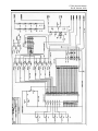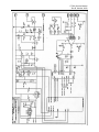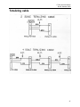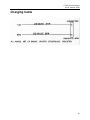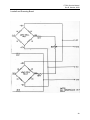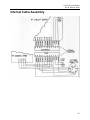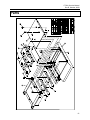
1
I
PT300
Service Manual
A & A Scales
1-813-994-3190
Fax 509-355-3498
www.stainlessscales.com
PT300, Service Manual
Rev B, October, 2000
SAFETY SUMMARY
The following general safety precautions must be observed during all phases of
operation, service, and repair of this scale. Failure to comply with these precautions or
with specific warnings elsewhere in this manual violates safety standards of design,
manufacture, and intended use of the scale. Intercomp assumes no liability for the
customer's failure to comply with these requirements.
DO NOT OPERATE IN AN EXPLOSIVE ATMOSPHERE.
Do not operate the scale in the presence of flammable gases or fumes. Operation of
any electrical instrument in such an environment constitutes a definite safety hazard.
DO NOT SUBSTITUTE PARTS OR MODIFY SCALE.
Because of the danger of introducing hazards, do not substitute parts or perform any
unauthorized modifications of the scale.
NOTICE
All rights reserved. The information contained in this publication is derived in part from proprietary and
patent data of the Intercomp corporation. This information has been prepared for the express purpose of
assisting operating maintenance personnel in the efficient use of the instrument described herein.
Publication of this information does not convey any rights to use or reproduce it or to use it for any
purpose other then in connection with the installation, operation, and maintenance of the equipment
described herein. While every precaution has been taken in the preparation of this manual, Intercomp
Corporation assumes no responsibility for damages resulting from the use of the information contained
herein. All instructions and diagrams have been checked for accuracy and ease of application; however,
success and safety in working with tools depend largely upon the individual accuracy, skill, and caution.
For this reason Intercomp Company is not able to guarantee the result of any procedure contained
herein. Nor can they assume responsibility for any damage to property or injury to persons occasioned
from the procedures. Persons engaging the procedures do so entirely at their own risk.
COMPLIANCE WITH FCC RULES
Please note that this equipment generates, uses, and can radiate radio frequency energy. If this
equipment is not installed and used in accordance with the support manual, you are warned that it may
cause interference to radio communications. This unit has been tested and has been found to comply
with the limits for a Class A computing device pursuant to subpart J of part 15 of FCC Rules. These
rules are designed to provide reasonable protection against interference when equipment is operated in a
commercial environment. However, if this unit is operated in a residential area, it is likely to cause
interference and under these circumstances the user will be required to take whatever measures are
necessary to eliminate the interference at his own expense.
1
PT300, Service Manual
Rev B, October, 2000
Table of Contents
SCOPE OF MANUAL ......................................................................................................................................... 5
SPECIFICATIONS.............................................................................................................................................. 6
ELECTRICAL....................................................................................................................................................... 6
SERIAL INTERFACE SPECIFICATIONS:.................................................................................................................... 6
PHYSICAL .......................................................................................................................................................... 6
ENVIRONMENTAL ............................................................................................................................................... 7
CALIBRATION:.................................................................................................................................................... 7
THEORY OF OPERATION ............................................................................................................................... 9
POWER SUPPLY:.................................................................................................................................................. 9
Input protection:........................................................................................................................................... 9
Charger:......................................................................................................................................................10
Switch:.........................................................................................................................................................10
Low Voltage Sensor: ....................................................................................................................................11
Regulator: ...................................................................................................................................................11
ANALOG SECTION: ............................................................................................................................................12
Instrumentation Amplifier:...........................................................................................................................12
Analog/Digital Converter: ...........................................................................................................................12
Microprocessor section: ..............................................................................................................................14
CPU:....................................................................................................................................................................... 14
Memory: ................................................................................................................................................................. 14
Device Selector: ...................................................................................................................................................... 14
Switches & Reader:................................................................................................................................................. 14
Display Driver: ....................................................................................................................................................... 15
Serial IN/OUT: ....................................................................................................................................................... 15
TROUBLESHOOTING .....................................................................................................................................16
SYMPTOMS........................................................................................................................................................16
No power up, nothing on display..................................................................................................................16
Power up to random display. .......................................................................................................................16
Power up to test pattern...............................................................................................................................16
Scale shuts off..............................................................................................................................................17
"Locks up." ..................................................................................................................................................17
No backlight. ...............................................................................................................................................17
No response to one or more keys..................................................................................................................17
"Bad" weights. .............................................................................................................................................17
Jumpy/drifty weights....................................................................................................................................17
Slow operation.............................................................................................................................................17
Low batt indicator won't turn off..................................................................................................................18
Batteries won't charge. ................................................................................................................................18
No totalizing................................................................................................................................................18
ERROR MESSAGES ..............................................................................................................................................18
TESTS, WAVEFORMS AND ..................................................................................................................................19
VOLTAGE MEASUREMENTS .................................................................................................................................19
Blank EPROM test.......................................................................................................................................19
SYSTEM CHECKOUT PROCEDURE .........................................................................................................................22
Charger voltage: .........................................................................................................................................22
On / Off switch: ...........................................................................................................................................22
Power Supplies:...........................................................................................................................................22
Amplifier: ....................................................................................................................................................23
A/D converter:.............................................................................................................................................23
Lamp: ..........................................................................................................................................................23
Keys: ...........................................................................................................................................................23
2
PT300, Service Manual
Rev B, October, 2000
Low batt indicator: ......................................................................................................................................23
Power down shutoff: ....................................................................................................................................23
SIO (totalizing):...........................................................................................................................................24
Load Cells:..................................................................................................................................................26
PROCEDURES...................................................................................................................................................27
LOADING PADS & BLOCKS..................................................................................................................................27
CALIBRATE SPAN ...............................................................................................................................................27
Calibration ..................................................................................................................................................27
REMOVE AND REPLACE MAIN CIRCUIT BOARD ......................................................................................................29
Disassembly.................................................................................................................................................29
Assembly .....................................................................................................................................................29
REMOVE AND REPLACE LOAD CELL .....................................................................................................................30
Disassembly.................................................................................................................................................30
Assembly .....................................................................................................................................................31
CHECK FRONT/BACK LOAD CELL BALANCE ..........................................................................................................31
UNPACKING AND INSTALLATION ........................................................................................................................34
USE OF A LOAD CELL SIMULATOR ........................................................................................................................34
COMPLETE LIST OF REQUIRED TOOLS AND MATERIALS .........................................................................................34
Spare parts list ............................................................................................................................................34
Connector pinouts .......................................................................................................................................36
TRANSMIT DATA FORMAT ..................................................................................................................................36
PT300 MAIN CIRCUIT BOARD ............................................................................................................................37
PARTS LIST .......................................................................................................................................................37
PT300 SUMMING CIRCUIT BOARD PARTS LIST .......................................................................................39
APPENDIX A......................................................................................................................................................40
APPENDIX B......................................................................................................................................................44
SCHEMATICS .....................................................................................................................................................44
TOTALIZING CABLE ...........................................................................................................................................47
CHARGING CABLE .............................................................................................................................................48
INTERNAL CABLE ASSEMBLY .............................................................................................................................50
PARTS.................................................................................................................................................................51
HOW TO REACH INTERCOMP SERVICE ...................................................................................................52
3
PT300, Service Manual
Rev B, October, 2000
Table of Illustrations
FIGURE 1 BLOCK DIAGRAM ................................................................................................. 8
FIGURE 2 BATTERY CHARGER ............................................................................................ 9
FIGURE 3 SWITCH ............................................................................................................ 10
FIGURE 4 INTEGRATOR/COMPARITOR ................................................................................ 12
FIGURE 5 CONVERSION CYCLE ......................................................................................... 13
FIGURE 6 LCD DRIVE ...................................................................................................... 15
FIGURE 7 BLANK EEPROM TEST WAVEFORMS ................................................................ 20
FIGURE 8 BLANK EEPROM TEST, ADDRESS LINES ........................................................... 21
FIGURE 9 TEST WAVEFORMS ........................................................................................... 22
FIGURE 10 SIO MASTER TEST ......................................................................................... 24
FIGURE 11 SIO SLAVE TEST ............................................................................................ 25
FIGURE 12 LOAD CELL SCHEMATIC ................................................................................... 26
FIGURE 13 LOAD CELL PLACEMENT .................................................................................. 32
FIGURE 14 SUMMING BOARD ............................................................................................ 40
4
PT300, Service Manual
Rev B, October, 2000
Scope of manual
This service manual describes the Intercomp PT300 scale specifications, theory of
operation, interconnection, calibration, and servicing. Please refer to the users manual
for detailed operating procedures and application information.
This manual is separated into several sections, each containing information on a
different aspect of the scale. The specifications show the design parameters for the
scale. The theory section includes a circuit description and theory of operation that
explains how the scale works. The service section provides information for
troubleshooting a defective circuit. The calibration section explains how to set the
scale adjustments. The interconnection section shows the way two or more scales
work together to form a larger system. The assembly instructions show correct
assembly and disassembly techniques.
This manual is not designed to be a substitute for proper training in the installation,
operation, maintenance or service of PT300 electronic scale. It is to be used as a
guide for training service personnel or as a reference source for training previously
received.
Caution
Your PT300 scale is covered by a one year warranty and should be referred to the
factory for maintenance within the warranty period. Attempts to make any extensive
repairs within the warranty period may invalidate the warranty. If repairs are needed
after the warranty period, only qualified technicians should attempt such repairs. An
understanding of the principles of operation of the PT300 circuitry as described herein
in necessary for rapid troubleshooting and repair of any scale malfunction.
5
PT300, Service Manual
Rev B, October, 2000
Specifications
Electrical
Display settling
time:
Accuracy:
Overcapacity:
Safe Overload:
Batteries:
Battery Life:
Battery Duration:
Automatic Shutoff:
Charging Voltage:
Charging Current:
Charging Time:
Low Batt.:
Fuse:
950 milliseconds to typical reading (static).
±1% of applied load
±1 display division in static mode
±2% of applied load
±1 display division in roll-over mode.
105% of nominal capacity.
150% of capacity.
6 x 1.2 volt AA nickel cadmium cells.
(Alkaline batteries can be used, but do not attempt to recharge
them).
Approximately 5 years. (1500 charge/discharge cycles).
Approximately 8 hours of continuous use before the low battery
indicator comes on, and 2 hours after that before the scale
shuts itself off.
The scale turns itself off when the battery voltage gets down to
approximately 6.3 volts.
11.5 volts - 14.5 volts DC. Protection is provided for accidental
reversal of the charging connections.
Starts at approximately 300 mA and drops down to 50 mA after
8 hours.
8 hours if the batteries are discharged to the point of turning off
the scale.
Indicator comes on when the battery voltage gets down to
approximately 7.2 volts.
Buss type AGC-1.
Serial interface specifications:
Interface:
Format:
1200 baud, 8 data, no parity, 2 stop bits.
Each print line contains
Physical
Overall Dimensions:
Platform Dimensions:
Scale Weight:
Display Height:
3 x 16 x 20 inches / 76 x 406 x 508 mm.
12 x 12 inches / 305 x 305 mm.
37 lb / 16.8 kg.
0.55” / 14mm
6
PT300, Service Manual
Rev B, October, 2000
All metal case provides EMI/RFI immunity.
Caution The scale and connecting cables should be operated at a minimum distance of
3 feet (1 meter) from any transmitting apparatus and least 10 feet (3.3 meters) from a
radiating antenna.
Environmental
Operating Temperature:
Humidity
-20 to 150º F (-28 to 65º C).
10 to 95% Non-Condensing.
Calibration:
All scales are calibrated at the factory, a fine span adjustment can be made using the
potentiometer on the PT300 circuit board.
This scale can be used while it is charging.
Caution
Operation outside the range of -20°F to 150°F (-28°C to 65°C) may result in inaccurate
weight values. Storage or operation outside the range of -40°F to 170°F (-40°C to
75°C) may result in a shift in calibration or damage to the scale.
7
PT300, Service Manual
Rev B, October, 2000
12v
Power Supply
On Off
Lamp
Lb/Kg
Zero
Hold/Rel
Total/Local
Print
Switches
Battery
Input
Buffer
Micro
Controller
Low Battery Sensor
Drivers
Display
Connector
Input
Connector
Serial
Input
Receiver
Serial
Output
Output
Loadcells
Summing
Board
Analog/Digital
Input
Figure 1 Block Diagram
8
PT300, Service Manual
Rev B, October, 2000
Theory of Operation
For the following discussion, please refer to the schematics in appendix B.
Power supply:
The power supply section provides a source of ±5 volts, a nickel-cadmium battery
charger, and the detector for low battery condition. The input is designed to accept any
voltage between 10.5 and 14.6 volts.
+14.6v-+10.5v
Current
C h a rge
L i m itin g
Sensor
Constant
Resistor
Current
R20
S o u rce
Q5
10.0v
D4
D20
9.3v
D5
S w itch
8.6v
Gnd
Gnd
B a tte r y
S c a le
Gnd
Gnd
Figure 2 Battery Charger
Input protection:
Diode D1 and fuse F1 provide protection from incorrectly connected power or a
circuit fault.
9
PT300, Service Manual
Rev B, October, 2000
Charger:
The battery charger works on the constant voltage charging principle. The diode
D4 is a 10 volt zener diode. This diode is biased by the constant current source
formed by R1, R2, Q8, D2, and D3. Current is sourced to D4 until the voltage
across R2 is equal to the voltage dropped across D2. D3 cancels the voltage
drop across the Vbe of Q8. R1 is used to draw a bias current through D2 and
D3. Q7 is configured as a common base amplifier, with 9.3 volts appearing on
emitter Q7 (10 volts from D4 minus 0.7 volts Vbe of Q7). R3 limits the charging
current to safe value. D5 is used to establish 8.6 volts across the string of cells.
The charge indicator circuit senses the current through R3. When 0.7 volts is
developed (about 28 milliAmps) across R3, Q10 turns on, lighting D20.
V Bat
Logic
Auto
Off
V Switched
R4
Q9
R6
R?
D6
Q5
On
Off
Gnd
Gnd
Gnd
Figure 3 Switch
Switch:
Q6 acts as the main power switch. R4 provides bias to hold Q6 off when in the
off state. Current is drawn through R5 to turn Q6 on. This current may be
provided by the ON switch contact, or through the transistor Q5. Q5 derives its
bias from the low voltage sensor of R6 and zener diode D6. While 6.8 volts is
present on the collector of Q6, D6 will conduct through the current limiting
resistor R6, and bias Q5 on. The OFF switch starves the base current of Q5.
This cuts off the base drive for Q6, turning the unit off. An output from the U12
(74HC191) may also hold D6 below turn on voltage, again, depriving Q5 of base
drive and indirectly turning off Q6 (auto off feature).
10
PT300, Service Manual
Rev B, October, 2000
Low Voltage Sensor:
R9, D7, and Q2 work much the same as R6, D6 and Q5 in the power switch
section. The addition of D8 causes Q2 to switch 0.3 volts before Q5. In
practical terms, Q2 will be biased on until the switched voltage drops to 7.2 volts.
Below this voltage the low voltage sense line goes high. R10 provides a path for
any leakage current through D7 and D8.
Regulator:
Q3 a standard 3 terminal regulator in a TO-92 package. U19 is a voltage
inverter chip that uses a charge pump to convert 5.0 volts to -5.0 volts. C1, C2,
and C3 are used to stabilize Q3, C5 and C6 are necessary to the operation of
U19.
11
PT300, Service Manual
Rev B, October, 2000
Analog Section:
The analog section takes the signal from the load cells (about 10 mV) and translates
this signal into a digital representation. In our case this representation is a sixteen bit
number in a counter register.
Instrumentation Amplifier:
The signal from the load cells is about 10 mV at full load. U18 takes this signal
and amplifies it for use by the A/D converter. R21, R22, C14, and C15 filter out
RFI interference and provide some limited protection from electrostatic
discharge. The total resistance between pins 2, 3, 6, 7, and 4 and 5 select the
gain of the amplifier. Some of the amplifier's built-in resistors are used to
increase the gain stability, hence the busy connections between U18 and the
gain selection resistors. R24 and potentiometer R24 are the gain selection
resistors. In the revision 'C' and later boards R52, R53, and jumpers JP1-JP3
allow jumper gain selection. R25, R26, C10, and C11 provide low pass
frequency filtering.
Analog/Digital Converter:
U17 is a collection of integrator, comparator and analog switches. With U12,
U13, and U14 this forms a dual slope integrating analog to digital converter.
The heart of the A/D converter is R17, C7, and an integrator and comparator
internal to U17. Please examine figure 4 below for the configuration of these
parts.
Integrator
Vref
C7
Vin
Comparitor
R17
+
+
Figure 4 Integrator/Comparitor
12
PT300, Service Manual
Rev B, October, 2000
Integrate
Deintegrate
U17 Pin 1
Auto Zero
Auto Zero
Figure 5 Conversion Cycle
Let’s examine the operation of the converter. Start with C7 at zero volts. The
+input voltage charges C7 for a fixed period called Time-integrate. Then the
integrator input is switched to the reference voltage and C7 is discharged for an
amount of time called Time-deintegrate; this time is related to the input voltage.
At sometime the voltage on C7 crosses zero, and the output of the comparator
changes state to reflect this. Another way of looking at the discharge cycle is
that the reference voltage does not change so the rate of discharge should be a
certain number of volts per second. The higher the input voltage, the higher the
voltage that will be driven onto the integrating capacitor. The higher the voltage
on the integrating capacitor, the longer the time of discharge. When the
integrator is not charging or discharging it is held in an "auto-zero" condition. At
this time any internal error voltages cancels inside U17. Note that the reference
voltage is simply the power supply divided by a resistor network. This is the
same supply used to power the load cells, so any change in the power supply
excitation to the load cells is canceled in the analog to digital converter. This
feature, adjusting the reference by the same amount as the excitation voltage, is
called ratiometric conversion.
13
PT300, Service Manual
Rev B, October, 2000
Now for the messy details of implementation; U17 is driven through the
integrate, deintegrate, and auto-zero cycles by a counter U12. This counter is
loaded by the micro processor to start the cycle, and U12 pin 6 output is used as
an interrupt to signal that the conversion is over. The counter's clock is driven
by ones output from the Counter-Timer-Chip, U13. The deintegrate phase is
signaled by ones on the control lines A and B into U17; this is combined with the
comparator output from U17 using Boolean AND function; gates clock pulses
into another section of U13. When the Micro is signaled that a conversion is
finished it reads a 16 bit number in U13 that is proportional to the weight on the
load cells. The micro clears the counters U12 and U13 pin 14, starting another
conversion cycle. Note that the MIN/MAX bit out of counter U12 is used as the
auto-off signal. To turn the scale off the computer does not service the end of
conversion interrupt. This also acts as a dandy watchdog timer, if the micro is
incapacitated it does not service the interrupt and the scale shuts off.
Microprocessor section:
This is the logic and timing portion of the system. The computer portion, user
interface and input/output sections fall in this category.
CPU:
U2 is a standard CMOS Z80 processor chip. Y1, U3A, U3B, and
associated parts form a 1.2 mHz clock. R37 and C20 form the power on
reset pulse.
Memory:
U5 is a 2K x 8 bit static RAM memory. A 27C64 EPROM (U1) holds
program and setup information. There is no NOVRAM or related
parameter storage. All setup parameters are set at fabrication and are
held in the EPROM device.
Device Selector:
U9 and several low level gates select all devices as memory. No refresh
or I/O cycles are needed or used.
Switches & Reader:
U4 reads all the switches except ON and OFF. Pin 17 of U4 reads the
serial input line, pin 4 reads the low battery line.
14
PT300, Service Manual
Rev B, October, 2000
Display Driver:
Any LCD display must be driven by a waveform with a net zero DC
voltage. If the driving voltage has any DC component the display will be
destroyed. A display driver chip (U10) provides the correct drive for 4 of
the display digits. The leading 100000's digit, the trailing 0/5 digit and all
annunciators are driven by U6, U7, and U8. U6 latches most of the
desired segment drive information. One line of U6 drives the serial output
circuitry. The low battery line is driven directly by the voltage sensor.
The EXCLUSIVE OR gates (U7 & U8) drive LCD segments with a signal
in phase with the backplane for off segments, and out of phase for on
segments.
O ff
On
Figure 6 LCD Drive
Serial IN/OUT:
U15 Reads a 20 mA current loop and converts this to an opto-isolated
TTL signal across R31. R29 and R30 act as a voltage divider to limit the
current through the current loop receiver diode. D17 provides a path for
reverse voltage spikes. U13 is programmed to output a regular 4800 Hz
pulse on pin 17, this is used as the source of non-maskable interrupt.
This timebase pulse is used to form a UART in software. U16 converts
TTL signals into either RS-232 or a 20 mA current loop signal. R34 acts
to limit the current in U16. D18 cancels the Vbe drop of Q4, allowing
current through R38 until its voltage drop matches D19 (0.7 Volt). This
results in 20 mA across the collector-emitter of Q4. When used as a RS232 transmitter, OIL- is grounded and the output is taken from OIL+. For
current loop, output is taken from OIL- and ground is taken on the other
side of the receiver logic.
15
PT300, Service Manual
Rev B, October, 2000
Troubleshooting
Caution
Changing some parts may cause a large change in calibration whereas others may or
may not change the calibration, depending on the nature of the problem. The most
sensitive parts are in the analog and power supply sections; this includes Q3, U17,
U18, U19, and their related resistors and capacitors. The areas that normally would
have no effect are: CPU, display and driver, memory chips, and serial interface
sections. Normally, the calibration should be checked after any repairs.
Symptoms
No power up, nothing on display.
If any power reaches the scale the display driver turns on some random
segments. Since we are not seeing this we will assume that no power is
reaching the scale circuitry. Some possible causes: blown fuse, shorted battery
pack, bad switch circuit, bad keypad, bad regulator. The power supply may be
delivering power, but it might be eaten up with a shorted circuit board or filter
capacitors.
Power up to random display.
We know that some power is reaching the display driver circuit, but the
microprocessor is not able run the display. Some possibilities: bad
microprocessor (U2), bad memory (U1, U5), bad chip select logic to memory or
display driver. Finally, the microprocessor may be working but the display driver
(U10) circuitry may not be working.
Power up to test pattern.
The microprocessor is running well enough to write to the display, but gets hung
up at some point after that. The usual symptom is the display stays on EEE0.
During the time between the display test and normal operation the scale is trying
to read a stable A/D value between certain limits. The A/D converter (U12, U13,
U17) may not be running at all. The converter may be returning values that are
outside of allowed ranges. Two reasons for this could be bad load cell outputs
or a bad amplifier chip (U18). The microprocessor may be defective, not reading
end of conversion interrupts, getting hung up in a loop, shorted address lines,
etc.
16
PT300, Service Manual
Rev B, October, 2000
Scale shuts off.
Normally the scale shuts itself off after a long period of inactivity. The length of
time is defined at the time the scale is configured, but is normally one hour. If
the microprocessor is acting up, one of the symptoms may be that the scale
shuts off after the A/D is initialized and starts to run. All this tells up is that the
microprocessor is not resetting the counter U12, so its reaching MIN/MAX count.
We do know that the microprocessor is getting far enough through the startup
routine to set up U13, as U13 does not emit any pulses until it's told to. If the
scale turns off IMMEDIATELY after you take your finger off the off button, you
may have defective power switch circuitry.
"Locks up."
Bad microprocessor (U2) or support circuitry.
No backlight.
Look for a bad keypad, connector. If only one string of lamps refuses to shine,
short out the unlit LEDs until you bridge the bad one.
No response to one or more keys.
The keypad or connector may be bad. U4 may be defective.
"Bad" weights.
First, check weighing technique. Are the scales being used by a new operator?
Are the scales being used on level ground? Are the operators using dummy
blocks on the unweighed wheels? If on a calibration press, are you using weight
distribution blocks and rubber pads? Is the reference scale correct? Assuming
all this, is the scale spanned correctly? Are the load cells bottoming out? If the
weight is exactly half of what you would expect, one of the two signal leads may
not be providing signal. This would probably be in the load cell or amplifier
(U18). Non-linearity would be in the load cell or the analog section. The
interconnecting wiring inside the scale may be pinched under the printed circuit
board.
Jumpy/drifty weights.
This can usually be traced to contamination on circuit boards, a bad load cell, or
a defective U18.
Slow operation.
If the clock is running at some sub-multiple of the clock frequency, the scale runs
very slowly, but correctly. It is also possible that the A/D converter circuitry is
not working well. The scale uses the A/D cycles to pace all its internal
operations. This problem is usually caused by a bad crystal.
17
PT300, Service Manual
Rev B, October, 2000
Low batt indicator won't turn off.
It is possible that the output from the batteries is really low. Look at the cells
and charger circuit for these problems. The low voltage sensor could be out.
The driver for the display could be bad.
Batteries won't charge.
The most common problem is the Fuse, start there. Check for bad batteries.
The charger circuit could be out. Check for bad connections or a defective
charging cable. Look at the power source, whether it's a plug-in transformer or
automotive ignition.
No totalizing.
This may be traced to a defect in a particular scale, or a defect in the
interconnecting cables. In an otherwise properly running scale you need to look
at the serial transmitter and receiver sections. Look for the clock running at the
wrong speed. Try pressing the print button, this should send the local weight
down to the next scale once each time the print button is pressed. Is each scale
in the totalizing mode? Look for the bar on the display. No scale will totalize if
its not stable or if is in an under or over capacity condition. Is the signal getting
from one scale to the next? Look for bad cables or connectors, outside or inside
the scales. The interconnecting wiring inside the scale may be pinched under
the printed circuit board.
Error messages
The following are messages you may see on the display, with the most likely meaning.
-OL
OL
EEEE
-=18888=
Input to A/D converter too low.
Input to A/C converter too high.
Weight not stable while zeroing.
A keyboard line is or was in the low state.
Power-up test pattern
18
PT300, Service Manual
Rev B, October, 2000
Tests, Waveforms and
Voltage measurements
Blank EPROM test.
One of the most challenging problems is finding a problem in the
"microprocessor kernel," that is, the RAM, ROM, microprocessor and related
circuitry. The hardest part is that everything is tied together, and if you cut it
apart, nothing works. The best way to tackle this problem is to run a VERY
simple test program. This allows you to determine that the microprocessor is
working first. Often, when the machine is "almost" working correctly, the
symptoms help you to find any remaining problems.
On a Z80 style microprocessor, the simplest test program is a BLANK EPROM.
If used properly, this program will find any shorted address lines, any shorted or
open data lines, any bad read, write, or chip select lines. It only uses the
microprocessor, ROM, and chip selector IC.
A blank EPROM returns 0FFH as the data. A quick look at the Z80 instruction
set shows this to be a short call to location 38H in memory. The microprocessor
pushes the current address location on wherever the stack pointer is pointing.
As the test runs the stack pointer decrements through every location in memory.
At location 38H the microprocessor reads another 0FFH. This repeats
indefinitely. Let’s examine this program on a cycle by cycle basis.
19
PT300, Service Manual
Rev B, October, 2000
CLK
RD
WR
__
MI
_____
RFSH
0038h
RFSH
0FFh
See Below
?
See Below
039h
00h
Figure 7 Blank EEPROM Test Waveforms
For the first three clock pulses the Z80 reads 0FFH from location 038H. As part
of an instruction fetch the Z80 does a memory refresh cycle. We do not use this
for anything, but its there. Then the Z80 writes out the address 0039 on the
stack. Note that this takes two write cycles. Each time the Z80 writes this out
the stack address changes so the address lines will count through all address.
The address lines can be examined one at a time. With practice you can verify
that these signals are correct in about two minutes. What you are looking for is
a characteristic pattern, with no "funny" voltage levels. A shorted line will be
unable to reach the low voltage levels. You may have to fiddle with the trigger
controls to get a stable display.
20
PT300, Service Manual
Rev B, October, 2000
A15 20mS/Div
A14 10mS/Div
A13 5mS/Div
A12 2mS/Div
A11 1mS/Div
A10 0.5 mS/Div
A09 0.1mS/Div
A08 50mS/Div
A07 0.1mS/Div
A06 0.1mS/Div
A05 0.1mS/Div
A04 50mS/Div
A03 20mS/Div
A02 10mS/Div
A01 5mS/Div
A00 2mS/Div
Figure 8 Blank EEPROM Test, Address Lines
21
PT300, Service Manual
Rev B, October, 2000
System checkout procedure
The following measurements are typical values. When tolerances are given the signal
must fall within the given ranges. Special measuring conditions will be specified as
needed. The measurements are given in the order that you should use them.
Condition: Scale is off and plugged into the charger. No cells installed. A variable
power supply connected to the power supply leads, set to 12.0V.
Charger voltage:
Positive battery lead, 8.6V
To check out the charger circuit, install cells.
Positive battery lead, 5.4V to 8.6V, depending on batteries state of charge.
On / Off switch:
Press the ON switch,
Q6, collector, 6.8V or greater.
Press the OFF switch.
Q6, collector, 0.7V or less.
Press the ON switch for the following tests.
Power Supplies:
U19, Pin 8 = 5.0V ±0.25V
U19, Pin 5 = -4.9V ±0.25V
U10 pin 5, 0.5mS/Div
U2 pin26, 5mS/Div
U3 pin 4, 0.2mS/Div
Figure 9 Test Waveforms
All signal measured with vertical gain set to 1 volt/division. For the reset pulse, ground
and release the reset pin while watching with the oscilloscope.
CAUTION:
22
PT300, Service Manual
Rev B, October, 2000
If the display backplane drive is missing, TURN THE SCALE OFF IMMEDIATELY.
Operation without a backplane signal will damage the display quickly. Remove the
display while determining the cause of the missing backplane signal. Display damage
will be evident as display segments that are on permanently, even with the scale off.
Amplifier:
No load on scale, or a load cell simulator set to 0.05 mV/V.
U18, Pin 11, zero input = 0.05 volts.
Apply 20000Lb, or a simulator set to 2.0 mV/V.
U18, Pin 11, full scale = 2.0V.
A/D converter:
U13, pin 14, zero input = About 1 millisecond width pulse.
U13, pin 14, full scale input = About 30 milliseconds width pulse.
Lamp:
Press the lamp key. All eight lamps light up.
Keys:
For each key, observe about five volts on the indicated pin. Press the key and
see zero volts. The display should show two minus signs. Release the key and
see five volts again.
U4, pin 6, press the Print key.
U4, pin 8, press the Lb/Kg key.
U4, pin 11, press the Local/Total key.
U4, pin 13, press the Hold/Release key.
U4, pin 15, press the Test/Zero key.
Low batt indicator:
Connect a variable supply to the input connector and remove the batteries.
Set the supply to 12V and turn the scale on.
Reduce the input voltage until the low battery just turns on.
Q6, collector, 6.5V to 6.8v.
Power down shutoff:
Continue the above test, reducing the power supply until the scale turns off.
Q6, collector, 5.25V to 6.0V.
23
PT300, Service Manual
Rev B, October, 2000
SIO (totalizing):
To test the totalizing function you will need 2 scales (one is the scale under test)
and a totalizing cable.
Put the scale under test into the master position, and the other scale in the
second position on the cable.
Scale under test
Slave
Leave any other cable
Disconnected
Figure 10 SIO Master Test
Turn both scales on. Wait until both scale go to a stable zero display. Insure that both
scales are in the totalizing mode, look for the bar next to TOT on the display. Press the
local/total key to turn on the bar if needed. Apply a load to the master scale. The same
weight should appear on the slave scale. If this test fails try pressing the print key.
The receiver must sense an open line condition to force a scale to become the master
scale. Pressing print will force an output anyway. This is useful in isolating between
an input and an output failure.
24
PT300, Service Manual
Rev B, October, 2000
Turn both scales off. Now put the scale under test in the slave position and the other
scale in the master position, like this . . .
Master
Scale under test
Leave any other cable
Disconnected
Figure 11 SIO Slave Test
Turn both scales on. Wait until both scale go to a stable zero display. Insure that both
scales are in the totalizing mode, look for the bar next to TOT on the display. Press the
local/total key to turn on the bar if needed. Apply a load to the master scale. The same
weight should appear on the scale under test.
25
PT300, Service Manual
Rev B, October, 2000
Load Cells:
Each PT300 scale has two load cells. These load cells are the transducers that
convert mechanical energy (weight) to electrical energy. Each load cell has 4
strain gages (1000 ohms each) and a temperature compensation resistor. The
four strain gages are wired together to form a Wheatstone bridge.
Color coding of the wires.
Red - + Excitation (5 Volts in this case)
Green - + Signal
White - - Signal
Black - - Excitation (ground)
EX+
1K
1K
1K
1K
5+
5-
EXFigure 12 Load Cell Schematic
The 200 ohm resistor in series with the Excitation lead is for temperature
compensation. It is a balco resistor that change resistance with temperature to
maintain a constant signal voltage. These resistors are specially manufactured for our
load cell material and strain gage types.
With the load cells disconnected from the summing board the resistances should be as
follows:
Blk - Red = 1200 Ohms
Blk - Grn = 751 Ohms
Blk - Wht = 751 Ohms
Wht - Grn = 1000 Ohms
With the two excitation leads soldered in place and the power on you should measure
approximately -1.00 to 1.00 millivolts between the plus and minus signal leads. The
signal at the main circuit board with everything soldered in place and the tare set
should be approximately 0.16 millivolts.
26
PT300, Service Manual
Rev B, October, 2000
Procedures
Please see Parts section for the parts drawing.
Loading pads & blocks.
At several points in the following procedures you will be asked to use loading blocks.
The tip of a test press may exert 20000 pounds of force. While PT300 scales are
designed to accept this force, they may not tolerate this on a single point. You must
use a block to distribute the force over the load surface. In general, the force should be
applied over much the same pattern as a truck tire. We suggest a 8" x 8" x 2 ± .25”
block of aluminum on top of an 8" x 8" x 0.5" piece of rubber.
Calibrate span
Tools required
Twenty thousand pound calibration press.
8" x 8" x 2 ± .25” aluminum loading block.
8" x 8" x 0.5" rubber loading pad.
Static dissipation station.
#2 Phillips screwdriver for bezel and board mounts.
Small slotted blade screwdriver.
Torque-seal potentiometer shaft sealer.
Caution:
The following procedure must only be performed at a static controlled workstation. The
main printed circuit board is subject to damage by electrostatic discharge.
Calibration
1) Remove all 10 bezel screws.
2) Detach keyboard assembly and set aside. Do not unplug keyboard.
3) Turn scale ON.
4) Wait for scale to warm up.
5) Zero the scale.
6) Apply a 10000 Lb load using loading block and pad centered on scale.
7) Adjust the span potentiometer as needed to show 10000 on the display.
(clockwise to increase, CCW to decrease) If you run out of potentiometer
travel please refer to appendix A (section titled “Selecting Initial Span Range”)
to change the span resistor.
8) Tap the span potentiometer to seat wiper.
9) Remove the test weight.
10) Repeat steps 5 to 9 until unit shows 10000.
27
PT300, Service Manual
Rev B, October, 2000
11) Apply 5000, 10000, 15000, and 19000 lbs and verify span is within 1.0% of
applied load. Make any adjustments necessary to bring the unit into
tolerance. Insure that unit does not indicate overcapacity before 20000 lbs
of applied weight.
12) Apply Torx-seal to lock the potentiometer shaft.
13) Reassemble keyboard assembly.
14) Replace bezel screws.
28
PT300, Service Manual
Rev B, October, 2000
Remove and replace main circuit board
Tools required
Twenty thousand pound calibration press.
8" x 8" x 2 ± .25” aluminum loading block.
8" x 8" x 0.5" rubber loading pad.
Static dissipation station.
#2 Phillips screwdriver for bezel and board mounts.
Small slotted blade screwdriver.
Torque-seal potentiometer shaft sealer.
Caution:
The following procedure must only be performed at a static controlled workstation. The
main printed circuit board is subject to damage by electrostatic discharge.
Disassembly
1) Remove all 10 bezel screws.
2) Detach keyboard assembly, unplug keyboard connector and set aside.
3) Remove 2 screws holding circuit board.
4) Remove main circuit from housing.
5) Unplug harness connector.
Assembly
1) Plug printed circuit into harness connector.
2) Place circuit board into housing. Be careful not to pinch the wires between
the battery tube and the printed circuit board.
3) Install two board mounting screws.
4) Plug in keyboard.
5) Check and adjust calibration as needed.
6) Align keyboard on housing.
7) Install 10 bezel screws.
29
PT300, Service Manual
Rev B, October, 2000
Remove and replace load cell
Tools required
Twenty thousand pound calibration press.
8" x 8" x 2 ± .25” aluminum loading block.
8" x 8" x 0.5" rubber loading pad.
Static dissipation station for any P.C. board work.
#2 Phillips screwdriver for bezel and board mounts.
Torque wrench covering 12 ft-lbs.
Torx T30 bit.
Small slotted blade screwdriver.
Locktite 242 removable Threadlocker (BLUE).
Torque-seal potentiometer shaft sealer.
Dow-Corning 3145 electronic grade RTV Adhesive/Sealant.
Soldering iron and solder.
Caution:
The following procedure must be performed at a static controlled workstation. The
main printed circuit board is subject to damage by electrostatic discharge.
Disassembly
1) Remove all 10 bezel screws.
2) Detach keyboard assembly and set aside. Do not unplug keyboard.
3) Remove 2 screws holding circuit board.
4) Remove main circuit from housing.
5) Unplug wire harness, set board and keyboard aside.
6) Peel insulator from back of summing board.
7) Record connection and color code of cell to be removed.
8) Unsolder loadcell leads from summing board.
9) Rotate summing board until potentiometer is accessible.
10) Remove 4 bolts holding platform.
11) Remove platform.
12) Remove 2 bolts holding load cell to platform.
13) Pull lead from load cell through hole in case.
14) Remove old loadcell from cavity.
15) Clean all old RTV from load cell lead feed-through hole.
30
PT300, Service Manual
Rev B, October, 2000
Assembly
16) Set new load cell in place.
17) Glue the load cell lead off to the side so it doesn’t run under the middle of
the load cells.
18) Thread load cell lead through hole in case.
19) Apply RTV liberally where load cell lead enters case. Work RTV compound
inside feed-through hole.
20) Replace strap assembly.
21) Replace 8 bolts holding strap assembly. Use permanent locktite (RED) and
torque bolts to 12 ft-lbs.
22) Replace platform.
23) Replace 6 bots holding platform. Use removable locktite (BLUE) and torque
bolts to 12 ft-lbs.
24) Solder load cell leads to summing board, using the same color code hookup
as the removed load cell.
25) Clean soldering flux from newly soldered leads.
26) Check and adjust load cell deadload. Please see appendix A for details.
27) Replace insulator on back of summing board.
28) Return summing board in housing.
29) Place circuit board into housing. Be careful not to pinch the wires between
the battery tube and the printed circuit board.
30) Install two board mounting screws.
31) Check and adjust the front/back load cell balance given in the following
procedure.
32) Check and adjust calibration as needed (see calibration procedure).
33) Reassemble keyboard assembly.
34) Replace bezel screws.
Check front/back load cell balance
Tools required
Twenty thousand pound calibration press.
1.5" x 1.5" x 12" aluminum loading block.
Static dissipation station.
#2 Phillips screwdriver for bezel and board mounts.
Small slotted blade screwdriver.
Torque-seal potentiometer shaft sealer.
Caution:
The following procedure must be performed at a static controlled workstation. The
main printed circuit board is subject to damage by electrostatic discharge.
Load cell locations used in the following procedure.
31
PT300, Service Manual
Rev B, October, 2000
2
1
Figure 13 Load Cell Placement
1) Remove all 10 bezel screws.
2) Detach keyboard assembly and set aside. Do not unplug keyboard.
3) Remove 2 screws holding circuit board.
4) Remove main circuit from housing.
Do not set the board on any conductive surface, including the scale.
5) Rotate summing board until potentiometer is accessible.
6) Turn scale ON.
7) Wait for scale to warm up.
8) Zero the scale.
9) Apply 5000 lb load to load cell #1 and record weight
10) Record displayed weight.
11) Apply a 5000 lb load to front load cell using loading block.
12) Adjust displayed weight to middle of front and back weight values.
13) Repeat steps 8 through 12 until there is no more than 1 division difference
between the front and back cells.
14) Apply Torx-seal to lock the potentiometer shaft.
15) Return summing board in housing.
16) Place circuit board into housing. Be careful not to pinch the wires between
32
PT300, Service Manual
Rev B, October, 2000
the battery tube and the printed circuit board.
17) Install tow board mounting screws.
18) Check and adjust calibration as needed.
19) Reassemble keyboard assembly
20) Replace bezel screws
33
PT300, Service Manual
Rev B, October, 2000
Unpacking and Installation
Caution:
Keep all packing materials in case scale must be shipped again. If the packing material
are lost or damaged, contact the service department for a replacement shipping carton.
Units shipped in any other materials will automatically void the warranty.
Use of a load cell simulator
During circuit board checkout it may be awkward to apply 20000 pounds to develop
internal signals. A load cell simulator may be attached to the signal and excitation
terminals to simulate these same signals. A setting of 2 mV/V gives about the same
signal as a 20000 Lbs load.
Complete list of required tools and materials
In addition the usual workbench and good lighting, the following list of tools and
materials would be necessary to set up a complete PT-300 service station.
Twenty thousand pound calibration press.
1.5" x 1.75" x 12” aluminum loading block.
8" x 8" x 1.75" aluminum loading block.
8" x 8" x 0.5" rubber loading pad.
Static dissipation station for any P.C. board work.
#2 Phillips screwdriver for bezel and board mounts.
Torque wrench covering 12 ft-lbs.
Torx T30 bit and driver.
Small slotted blade screwdriver.
Locktite 242 removable Threadlocker (BLUE).
Locktite 262 permanent Threadlocker (RED).
Torque-seal potentiometer shaft sealer.
Dow-Corning 3145 electronic grade RTV Adhesive/Sealant.
Soldering iron and solder.
Spare parts list
These common parts can prevent "nuisance" downtime:
Fuses.
Battery pack.
To set up a "well stocked" service depot, the following parts are useful:
34
PT300, Service Manual
Rev B, October, 2000
Spare keypad.
Main circuit board.
Summing board.
Load Cells.
Check straps.
Charging transformer.
Span resistors, 124Ω , 174Ω .
35
PT300, Service Manual
Rev B, October, 2000
Connector pinouts
A: +5V
B: - Input
C: Ground
D: - Output
E: +12V (Charging Voltage)
F: + Input
G: Unused
H: + Output
Transmit Data format
M
Kg
Format = A_O_-XXXXXXX._Lb<CR><LF>
Z
Format explanation:
A = Scale code (Signifies the scale, could
be A for scale A, B for scale B etc..)
Space
M,O,Z = Error code
M = motion,
O = overcapacity,
Z = zero,
space = no error
Space
Minus sign if negative, space if positive.
8 data bits
Space
Units code, Pounds or Kilos
Carriage return
Line feed
36
PT300, Service Manual
Rev B, October, 2000
PT300 Main Circuit Board
Parts List
PT300 Circuit Board
1.22Mhz Crystal
Liquid Crystal Display
(LXD # 65R9F09KGJ)
LED’s
Right Angle Post Header
AMP #1-640457-0
28 pin DIP Socket
AMP #6415615-3
Display Stand Offs
Samtec #ECC-117-TT/03
Fuse Clips
DIGI KLIP #MC-27
6 pin Dual Row Header Posts
3M #2406-6122
Fuse, Buss type AGC-1
5pF Ceramic Disc, 50v Radial Leads
.01uF Ceramic Disc, 50v Radial Leads
0.1uF Polypropylene, 100v Axial Leads
0.1uF Ceramic Disc, 25v Radial Leads
0.33uF Polypropylene, 200v Axial Leads
1.0uF Tantalum, 35v Radial Leads
10uF Tantalum, 35v Radial Leads
100uF Electrolytic, 16v Radial Leads
50 ohm Pot, Vishay #1240 type W
22 ohm, ¼ w, 5%
25 ohm, 5 w 5%
27 ohm, ¼ w 5%
33 ohm, ¼ w 5%
47 ohm, ¼ w 5%
150 ohm, ¼ w 1%
220 ohm ¼ w 5%
270 ohm ¼ w 5%
301 ohm ¼ w 1%
330 ohm ¼ w 1%
1K ohm ¼ w 1%
1K ohm ¼ w 5%
1.5K ohm ¼ w 5%
Reference:
DS1
D9,D10,D11,D12,
D13,D14,D15,D16
Quantity:
1
1
8
1
1
4
2
JP1
C18
C2,C14,C15,C21,C22,C23,C2
4,C25,C26,C27,C28,C29,C30,
C31,C32,C33,C34,C35,C36
C10,C11,C8
C20
C7
C3,C4,C9
C1,C5,C6,C12,C13,C16
C37
R23
R29
R3
R2
R38
R7,R8
R52
R30
R51
R24
R24
R21,R22
R1,R34,R35
R20
1
1
1
19
3
1
1
3
6
1
1
1
1
1
1
2
1
1
1
1
1
2
3
1
37
PT300, Service Manual
Rev B, October, 2000
4.7K ohm ¼ w 5%
10K ohm ¼ w 5%
10K ohm ¼ w 1%
47K ohm ¼ w 5%
100K ohm SIP, 8pin, #1 common
150K ohm ¼ w 1%
180K ohm ¼ w 5%
1M ohm ¼ w 5%
5M ohm ¼ w 5%
1N914
1N4001
1N5711
1N5240
1N5233B
LM340LA-5
2N2222
2N4402
4N35
74HC08
74HC14
74HC32
74HC86
74HC138
74HC191
74HC244
74HC373
UPD70008
6116
TSC500IJE
TSC7211AM
TSC7600
82C54(UPD71054C)
INA102AG Burr Brown
Wire Harness
R5,R31
R6,R9,R10,R32
R14
R50
RN1
R25,R26
R12
R4
R33
D2,D3,D18,D19
D1,D5,D17
D8
D4
D6,D7
Q3
Q2,Q4,Q5,Q7,Q9
Q6,Q8,Q10
U15,U16
U14
U3
U11
U7,U8
U9
U12
U4
U6
U2
U5
U17
U10
U19
U13
U18
2
4
1
1
1
2
1
1
1
4
3
1
1
2
1
5
3
2
1
1
1
2
1
1
1
1
1
1
1
1
1
1
1
1
38
PT300, Service Manual
Rev B, October, 2000
PT300 SUMMING CIRCUIT BOARD PARTS LIST
PT300 Summing Board Rev. 1
14pin Dual Row, 90º, Header
3M #2414-5222TG
10K ohm Trim Pot
47M ohm ¼ w 1%
15M ohm ¼ w 5%
22M ohm ¼ w 5%
500 ohm pot
header, 4-pin MTA
header, 7 x 2 pin, 90 degree
Reference:
JP1
Quantity:
1
R1,R2,R3,R4
R6
R8
R7
R5
P1, P2, TP1-4
JP1
4
1
1
1
1
3
1
39
PT300, Service Manual
Rev B, October, 2000
Appendix A
Setting the deadload.
The output signal from the load cells is set to a value slightly above zero with zero
weight applied. This is done for two reasons; one is to detect any errors in the load
cells, the other is to run the A/D converter in its most accurate operating point. The
"Deadload" or "Tare" must be set with no weight on the scale. This is not a regular
maintenance item, it should only need to be adjusted when changing a circuit board or
load cell. Please refer to the diagram below while reading the following section.
Figure 14 Summing Board
Function of JP1:
Position 1.
Position 2
Position 3
Position 4
Position 5
Position 6
Position 7
Lower raw counts
Raise raw counts
Not used
Not used
Selects R8 (15M)
Selects R7 (22M)
Selects R6 (47M)
Instructions on next page
40
PT300, Service Manual
Rev B, October, 2000
1)
It is assumed that the scale is disassembled with the main circuit board
removed from the case (but still plugged in) and sitting on an insulating
surface. The keypad must be plugged into the main circuit board.
2)
On the keypad, press the Local/Total and the lb/kg and while holding
them down turn the scale on and release all switches. The scale should
turn on with a number other than zero, we call this number the "raw
counts", ideally this number should be between 1500 and 4500. The
raw counts should change as weight is applied to the platform, (even a
small weight of 5 or 10 pounds should register a change) it will either
increase or decrease depending on the signal coming from the load
cells.
3)
If the raw counts are lower than 1500 or go down as weight is applied it
means that the negative signal is too high and needs to be lowered
(lowering the negative signal will increase the displayed raw counts).
Place a shunt in position 2 of JP1 and using trial and error place another
shunt in position 5, 6 or 7 whichever puts the displayed value between
1500 and 4500.
4)
If the raw counts are higher than 4500 and go up as weight is applied it
means that the positive signal is too high and needs to be lowered
(lowering the positive signal will decrease the displayed raw counts).
Place a shunt in position 1 of JP1 and using trial and error place another
shunt in position 5, 6 or 7 whichever puts the raw counts between 1500
and 4500.
5)
Deadload adjustment complete.
41
PT300, Service Manual
Rev B, October, 2000
Selecting the Initial Span Range.
It may be necessary to change the span resistor if you run out of travel when setting
scale span. Likewise the span resistor may have to be changed when new circuit
boards or load cells are installed.
There are two revision boards; 300B and 300C. With the 300B board the span resistor
(R24) must be unsoldered to change values. The 300C board has a shorting plug
selecting a span resistor (R24, R52 or R53).
If you need more span (run out of travel going clockwise), select the next lower resistor
in this series: 274Ω , 301Ω , 330Ω , 365Ω , 392Ω . If you need less span (run out of
travel going counter-clockwise), select the next higher resistor in the series. These
resistors must be 1% tolerance parts.
With the revision B board, you must unsolder the old resistor and solder in the new
part.
With the revision C board the two most common values, 330Ω and 365Ω are selectable
with a shorting plug. JP1-1 goes to R24/330Ω and JP1-2 goes to R53/365Ω . Any
values outside this range will need to be soldered in place. Put the new resistor in
place of R52, and move the jumper to JP1-3.
With either board, clean off any soldering flux after changing a span resistor. Failure to
do this may result in inaccurate weight measurement.
Now try the span adjustment, and insure that you have enough adjustment range.
42
PT300, Service Manual
Rev B, October, 2000
Schematics and Parts layout
Number
072391-102
None
None
None
None
000196
Title
PT300 Schematic
PT300 Board Assembly
PT300 Internal harness
PT300 Summing Board
Scale Interconnect Cables
PT300 Assembly
Pages
3
1
1
1
2
1
43
PT300, Service Manual
Rev B, October, 2000
Appendix B
Schematics
44
PT300, Service Manual
Rev B, October, 2000
45
PT300, Service Manual
Rev B, October, 2000
46
PT300, Service Manual
Rev B, October, 2000
Totalizing cable
47
PT300, Service Manual
Rev B, October, 2000
Charging Cable
48
PT300, Service Manual
Rev B, October, 2000
Loadcell and Summing Board
49
PT300, Service Manual
Rev B, October, 2000
Internal Cable Assembly
50
PT300, Service Manual
Rev B, October, 2000
Parts
51