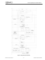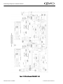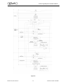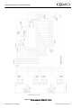
1
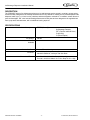
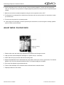
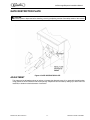
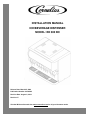
INSTALLATION MANUAL
ICE/BEVERAGE DISPENSER
MODEL: ED 300 BC
Release Date: March 25, 2004
Publication Number: 92166INS
Revision Date: August 3, 2010
Revision: E
Visit the IMI Cornelius web site at www.cornelius.com for all your Literature needs.
The products, technical information, and instructions contained in this manual are subject to change without notice.
These instructions are not intended to cover all details or variations of the equipment, nor to provide for every possible contingency in the installation, operation or maintenance of this equipment. This manual assumes that the person(s) working on the equipment have been trained and are skilled in working with electrical, plumbing, pneumatic,
and mechanical equipment. It is assumed that appropriate safety precautions are taken and that all local safety and
construction requirements are being met, in addition to the information contained in this manual.
This Product is warranted only as provided in Cornelius’ Commercial Warrant applicable to this Product and is subject to all of the restrictions and limitations contained in the Commercial Warranty.
Cornelius will not be responsible for any repair, replacement or other service required by or loss or damage resulting
from any of the following occurrences, including but not limited to, (1) other than normal and proper use and normal
service conditions with respect to the Product, (2) improper voltage, (3) inadequate wiring, (4) abuse, (5) accident,
(6) alteration, (7) misuse, (8) neglect, (9) unauthorized repair or the failure to utilize suitably qualified and trained persons to perform service and/or repair of the Product, (10) improper cleaning, (11) failure to follow installation, operating, cleaning or maintenance instructions, (12) use of “non-authorized” parts (i.e., parts that are not 100%
compatible with the Product) which use voids the entire warranty, (13) Product parts in contact with water or the
product dispensed which are adversely impacted by changes in liquid scale or chemical composition.
Contact Information:
To inquire about current revisions of this and other documentation or for assistance with any Cornelius product contact:
www.cornelius.com
800-238-3600
Trademarks and Copyrights:
This document contains proprietary information and it may not be reproduced in any way without permission from
Cornelius.
Printed in U.S.A.
TABLE OF CONTENTS
Safety Instructions . . . . . . . . . . . . . . . . . . . . . . . . . . . . . . . . . . . . . . . . . . . . . . . . . . . . . . . . . . . . . 1
Read And Follow All Safety Instructions . . . . . . . . . . . . . . . . . . . . . . . . . . . . . . . . . . . . . . . . . 1
Safety Overview . . . . . . . . . . . . . . . . . . . . . . . . . . . . . . . . . . . . . . . . . . . . . . . . . . . . . . . . 1
Recognition . . . . . . . . . . . . . . . . . . . . . . . . . . . . . . . . . . . . . . . . . . . . . . . . . . . . . . . . . . . . 1
Different Types Of Alerts . . . . . . . . . . . . . . . . . . . . . . . . . . . . . . . . . . . . . . . . . . . . . . . . . . . . . 1
Safety Tips . . . . . . . . . . . . . . . . . . . . . . . . . . . . . . . . . . . . . . . . . . . . . . . . . . . . . . . . . . . . . . . . 1
Qualified Service Personnel. . . . . . . . . . . . . . . . . . . . . . . . . . . . . . . . . . . . . . . . . . . . . . . . . . . 1
Safety Precautions . . . . . . . . . . . . . . . . . . . . . . . . . . . . . . . . . . . . . . . . . . . . . . . . . . . . . . . . . 2
Shipping And Storage . . . . . . . . . . . . . . . . . . . . . . . . . . . . . . . . . . . . . . . . . . . . . . . . . . . . . . . 2
Co2 (Carbon Dioxide) Warning . . . . . . . . . . . . . . . . . . . . . . . . . . . . . . . . . . . . . . . . . . . . . . . . 2
Mounting In Or On A Counter . . . . . . . . . . . . . . . . . . . . . . . . . . . . . . . . . . . . . . . . . . . . . . . . . 2
Description . . . . . . . . . . . . . . . . . . . . . . . . . . . . . . . . . . . . . . . . . . . . . . . . . . . . . . . . . . . . . . . . . . 3
Installation Instructions . . . . . . . . . . . . . . . . . . . . . . . . . . . . . . . . . . . . . . . . . . . . . . . . . . . . . . . . . 4
Installation . . . . . . . . . . . . . . . . . . . . . . . . . . . . . . . . . . . . . . . . . . . . . . . . . . . . . . . . . . . . . 4
Adjust Water -to-syrup Ratio . . . . . . . . . . . . . . . . . . . . . . . . . . . . . . . . . . . . . . . . . . . . . . . . . . 5
Gate Restrictor Plate . . . . . . . . . . . . . . . . . . . . . . . . . . . . . . . . . . . . . . . . . . . . . . . . . . . . . . . . . . 6
Adjustment . . . . . . . . . . . . . . . . . . . . . . . . . . . . . . . . . . . . . . . . . . . . . . . . . . . . . . . . . . . . . . . . . . 6
Troubleshooting . . . . . . . . . . . . . . . . . . . . . . . . . . . . . . . . . . . . . . . . . . . . . . . . . . . . . . . . . . . . .
Blown Fuse Or Circuit Breaker . . . . . . . . . . . . . . . . . . . . . . . . . . . . . . . . . . . . . . . . . . . . . . .
Gate Does Not Open. Agitator Does Not Turn. . . . . . . . . . . . . . . . . . . . . . . . . . . . . . . . . . . .
Gate Does Not Open Or Is Sluggish. Agitator Turns . . . . . . . . . . . . . . . . . . . . . . . . . . . . . .
Ice Dispenses Continuously. . . . . . . . . . . . . . . . . . . . . . . . . . . . . . . . . . . . . . . . . . . . . . . . . .
Slushy Ice. Water In Hopper . . . . . . . . . . . . . . . . . . . . . . . . . . . . . . . . . . . . . . . . . . . . . . . . .
Beverages Do Not Dispense . . . . . . . . . . . . . . . . . . . . . . . . . . . . . . . . . . . . . . . . . . . . . . . . .
Beverages Too Sweet . . . . . . . . . . . . . . . . . . . . . . . . . . . . . . . . . . . . . . . . . . . . . . . . . . . . . .
Beverage Not Sweet Enough . . . . . . . . . . . . . . . . . . . . . . . . . . . . . . . . . . . . . . . . . . . . . . . .
Beverages Not Cold (Units With Built-in Cold Plate).. . . . . . . . . . . . . . . . . . . . . . . . . . . . . . .
Flavor Syrups Do Not Dispense . . . . . . . . . . . . . . . . . . . . . . . . . . . . . . . . . . . . . . . . . . . . . .
Flavor Dispenses For More Than1sec . . . . . . . . . . . . . . . . . . . . . . . . . . . . . . . . . . . . . . . . .
Flavor Dispenses More Than .5 Oz . . . . . . . . . . . . . . . . . . . . . . . . . . . . . . . . . . . . . . . . . . .
13
13
13
13
13
13
13
13
13
13
14
14
14
Ice/Beverage Dispenser Installation Manual
SAFETY INSTRUCTIONS
READ AND FOLLOW ALL SAFETY INSTRUCTIONS
Safety Overview
•
Read and follow ALL SAFETY INSTRUCTIONS in this manual and any warning/caution labels on the unit (decals, labels or
laminated cards).
•
Read and understand ALL applicable OSHA (Occupational Safety and Health Administration) safety regulations before
operating this unit.
Recognition
Recognize Safety Alerts
!
This is the safety alert symbol. When you see it in this manual or on the unit,
be alert to the potential of personal injury or damage to the unit.
DIFFERENT TYPES OF ALERTS
! DANGER:
Indicates an immediate hazardous situation which if not avoided WILL result in serious injury, death or equipment
damage.
! WARNING:
Indicates a potentially hazardous situation which, if not avoided, COULD result in serious injury, death, or equipment
damage.
! CAUTION:
Indicates a potentially hazardous situation which, if not avoided, MAY result in minor or moderate injury or equipment
damage.
SAFETY TIPS
•
Carefully read and follow all safety messages in this manual and safety signs on the unit.
•
Keep safety signs in good condition and replace missing or damaged items.
•
Learn how to operate the unit and how to use the controls properly.
•
Do not let anyone operate the unit without proper training. This appliance is not intended for use by very young children or
infirm persons without supervision. Young children should be supervised to ensure that they do not play with the appliance.
•
Keep your unit in proper working condition and do not allow unauthorized modifications to the unit.
QUALIFIED SERVICE PERSONNEL
! WARNING:
Only trained and certified electrical, plumbing and refrigeration technicians should service this unit. ALL WIRING AND
PLUMBING MUST CONFORM TO NATIONAL AND LOCAL CODES. FAILURE TO COMPLY COULD RESULT IN
SERIOUS INJURY, DEATH OR EQUIPMENT DAMAGE.
Publication Number: 92166INS
-1-
© 2004-2010, IMI Cornelius Inc.
Ice/Beverage Dispenser Installation Manual
SAFETY PRECAUTIONS
This unit has been specifically designed to provide protection against personal injury. To ensure continued protection
observe the following:
! WARNING:
Disconnect power to the unit before servicing following all lock out/tag out procedures established by the user. Verify
all of the power is off to the unit before any work is performed.
Failure to disconnect the power could result in serious injury, death or equipment damage.
! CAUTION:
Always be sure to keep area around the unit clean and free of clutter. Failure to keep this area clean may result in
injury or equipment damage.
SHIPPING AND STORAGE
! CAUTION:
Before shipping, storing, or relocating the unit, the unit must be sanitized and all sanitizing solution must be drained
from the system. A freezing ambient environment will cause residual sanitizing solution or water remaining inside the
unit to freeze resulting in damage to internal components.
CO2 (CARBON DIOXIDE) WARNING
! DANGER:
CO2 displaces oxygen. Strict attention MUST be observed in the prevention of CO2 gas leaks in the entire CO2 and
soft drink system. If a CO2 gas leak is suspected, particularly in a small area, IMMEDIATELY ventilate the
contaminated area before attempting to repair the leak. Personnel exposed to high concentrations of CO2 gas
experience tremors which are followed rapidly by loss of consciousness and DEATH.
MOUNTING IN OR ON A COUNTER
! WARNING:
When installing the unit in or on a counter top, the counter must be able to support a weight in excess of 730 lbs. to
insure adequate support for the unit. FAILURE TO COMPLY COULD RESULT IN SERIOUS INJURY, DEATH OR
EQUIPMENT DAMAGE.
NOTE: Many units incorporate the use of additional equipment such as icemakers. When any addition
equipment is used you must check with the equipment manufacturer to determine the additional weight
the counter will need to support to ensure a safe installation.
©2004-2010, IMI Cornelius Inc.
-2-
Publication Number: 92166INS
Ice/Beverage Dispenser Installation Manual
DESCRIPTION
The “ENDURO” series of ice dispensers solves your ice and beverage service needs in a sanitary, space saving,
economical way. Designed to be manually filled with ice from any remote ice-making source, these dispensers will
dispense cubes (up to 1-1/4 inch in size), cubelets, and hard-chipped or cracked ice. In addition, several flavors of
post-mix beverages. “BC” units include beverage faucets and a cold plate and are designed to be supplied direct
from syrup tanks and carbonator, with no additional cooling required.
SPECIFICATIONS
Model Descriptions:
ED300(Ice only)
B=(Beverage Faucets)
BC=(Faucets andCold Plate)
Z=(No Drip)
F=(Flavor Option)
Ice Storage:
Maximum number of Faucets
Available
Built-in Cold Plate:
Electrical:
Dimensions ED 150:
Publication Number: 92166INS
300 lbs
12
Yes, on BC models only
120/1/60Hz, 5.2 Amps Total Unit Draw
220-240/1/50/60 Hz, 4.0 Amps Total Unit Draw
44-3/8 in. Wide X 31-1/2 in. Deep X 37 in. High
Z model = 44-3/8 in. Wide X 23-1/16 in. Deep X 37 in. High
-3-
© 2004-2010, IMI Cornelius Inc.
Ice/Beverage Dispenser Installation Manual
INSTALLATION INSTRUCTIONS
INSTALLATION
! WARNING:
TO THE INSTALLER.
It is the responsibility of the Installer to ensure that the water supply to the dispensing equipment is provided with
protection against backflow by an air gap as defined in ANSI/ASME A112. 1.2-1979; or an approved vacuum
breaker or other such method as proved effective by test and must comply with all federal state and local codes,
failure to comply could result in serious injury, death or damage to the equipment.
Water pipe connections and fixtures directly connected to a potable water supply shall be sized, installed, and
maintained according to Federal, State, and Local laws.
1. Locate the dispenser indoors on a level counter top.
A. LEG OPTION, Kit P/N 08017
NOTE: Before Installing legs, the plastic plugs (6) in the base threaded holes must be removed.
Unpack the four (4) legs and install them into the threaded holes provided in the bottom of the unit.
The installer must provide flexibility in the product and utility supply to permit shifting the position of the
dispenser sufficiently to clean the area beneath it.
B. COUNTER MOUNTING
The ice dispenser must be sealed to the counter. The template drawing (see Figure 3) indicates where
openings can be cut in the counter. Locate the desired position for the dispenser, then mark the outline
dimensions on the counter using the template drawings. Cut openings in counter.
Apply a continuous bead of NSF International (NSF) silastic sealant (Dow 732 or equal) approximately
1/4--inch inside of the unit outline dimensions and around all openings. Then, position the unit on the counter
within the outline dimensions. All excess sealant must be wiped away immediately.
2. The beverage tubes, drain tube and power cord are routed through the large opening in the bottom of the unit.
See the MOUNTING TEMPLATE (Figure 3 or 4) for locating the required clearance opening in the counter for
these utility lines.
3. DRIP TRAY DRAIN ASSEMBLY (see Figure 5): Route the drain tube to an open drain with the end of the tube
above the “flood” level of the drain. Use the tubing, fittings, clamps, and insulation provided with the Dispenser
to assemble the drain. The completed drain line must pitch continuously downward and contain no “traps” or
improper drainage will result.
4. Connect the beverage system product tubes as indicated in the Beverage System Schematic. This workshould
be done by a qualified service person.
NOTE: See applicable Plumbing Diagram (see Figure 6, 7, 8, or 9) or Decal on the lower front panel of the
unitfor the location of syrup and water connections.
5. Clean the hopper interior (see CLEANING INSTRUCTIONS in Owner’s Manual).
! WARNING:
This unit must be grounded to aviod possiable fatal electrical shock or serious injury to the opertor. The unit power
card is equiped with a three prong plug. if a Three-hole (grounded) outlet is not avilable and use an approved method
to ground the unit. Failure to comply could result in serious injury, death or damage to the equipment.
©2004-2010, IMI Cornelius Inc.
-4-
Publication Number: 92166INS
Ice/Beverage Dispenser Installation Manual
6. Connect the power cord to a 120 volt, 60 cycle, 3-wire grounded receptacle. For 220--240 volt International
units, a 3--wire power cord is provided. An adapter plug for the particular country will need to be provided by the
Installer.
7. Maximum and minimum ambient temperature rating for correct operation is 40 to 105 F
8. The dispenser is not designed for a wash down environment and must not be placed in an area where a water
jet could be used.
9. The uint has to be placed in a horizontal position.
10. If the supply cord is damaged, it must be replaced by the manufacturer, it’s service agent or similarly qualified
person in order to avoid a hazard.
ADJUST WATER -TO-SYRUP RATIO
Figure 1
1. Remove valve cover and install syrup separator over the difiuser and throug the nozzle.
2. Hold cup under valve and dispenser beverage for a specific time (i.e. 2 seconds)
3. NOTE: water and syrup must be cold before checking ratios.
4. Adjust carbonated water flow to the desired rate (such as 90 to 100 ml (3 to 3.75 oz.) per second). Turn the flow
adjuster 1/4 of a turn at a time and recheck the flow. To increase reading turn clockwise.
5. Set a syrup flow adjuster to get the desired ratio.
6. Test the valve and adjust until a consistent ratio is delivered three consecutive times.
7. Repeat procedure for other valves.
Publication Number: 92166INS
-5-
© 2004-2010, IMI Cornelius Inc.
Ice/Beverage Dispenser Installation Manual
GATE RESTRICTOR PLATE
!
CAUTION:
Disconnect power to dispenser before installing, removing oradjusting restrictor. See safety section of this manual.
Figure 2. GATE RESTRICTOR PLATE
ADJUSTMENT
This plate may be adjusted as shown to reduce or increase the dispensing rate of ice, especially desirable when
using glasses or other containers with small openings. Adjustment can be made by sliding up or down with nuts
loosened, to obtain the desired amount of restriction.
©2004-2010, IMI Cornelius Inc.
-6-
Publication Number: 92166INS
Ice/Beverage Dispenser Installation Manual
Figure 3. Mounting Template (Ice only-B Models)
Figure 4. Mountin Template (BC Models)
Publication Number: 92166INS
-7-
© 2004-2010, IMI Cornelius Inc.
Ice/Beverage Dispenser Installation Manual
Figure 5. Drip Tray Drain Assembly
©2004-2010, IMI Cornelius Inc.
-8-
Publication Number: 92166INS
Ice/Beverage Dispenser Installation Manual
Figure 6. Flow Diagram (BC Model with Eight Beverage Faucets)
Publication Number: 92166INS
-9-
© 2004-2010, IMI Cornelius Inc.
Ice/Beverage Dispenser Installation Manual
Figure 7. Flow Diagram (B Models with Ten Beverage Faucets)
©2004-2010, IMI Cornelius Inc.
- 10 -
Publication Number: 92166INS
Ice/Beverage Dispenser Installation Manual
Figure 8. Flow Diagram (BC Models with Twelve Beverage Faucets)
Publication Number: 92166INS
- 11 -
© 2004-2010, IMI Cornelius Inc.
Ice/Beverage Dispenser Installation Manual
Figure 9. Flow Diagram (B Models with Twelve Beverage Faucets)
©2004-2010, IMI Cornelius Inc.
- 12 -
Publication Number: 92166INS
Ice/Beverage Dispenser Installation Manual
TROUBLESHOOTING
IMPORTANT: Only qualified personnel should service internal components or electrical wiring.
! WARNING:
If repairs are to be made to a product system, remove quick disconnects from the applicable product tank,
then relieve the system pressure before proceeding. If repairs are to be made to the CO2 system, stop
dispensing, shut off the CO2 supply, then relieve the system pressure before proceeding. If repairs are to
be made to the refrigeration system, make sure electrical power is disconnected from the unit.
Should your unit fail to operate properly, check that there is power to the unit and that the hopper containsice. If the
unit does not dispense, check the following chart under the appropriate symptoms to aid in locating the defect.
Trouble
Probable Cause
A. . Short circuit in wiring.
BLOWN FUSE OR CIRCUIT BREAKER. B. Defective gate solenoid.
C. Defective agitator motor.
GATE DOES NOT OPEN. AGITATOR
DOES NOT TURN.
A. No power.
B. Bent depressor plate (does not actuate
C. Defective dispensing switch.
GATE DOES NOT OPEN OR IS
SLUGGISH.
AGITATOR TURNS.
A. Defective gate solenoid
B. Excessive pressure against gate slide.
C. Defective Rectifier.
ICE DISPENSES CONTINUOUSLY.
A. Stuck or bent depressor plate (does not release switch).
B. Defective dispensing switch.
C. Improper switch installation.
SLUSHY ICE. WATER IN HOPPER.
A.
B.
C.
D.
BEVERAGES DO NOT DISPENSE.
A. No 24 volt power to faucets.
B. No CO2 pressure.
BEVERAGES TOO SWEET.
A. Carbonator not working.
B. No CO2 pressure in carbonator.
C. Faucet brix requires adjusting.
BEVERAGE NOT SWEET ENOUGH
A. Empty syrup tank
B. Faucet brix requires adjusting.
BEVERAGES NOT COLD (UNITS
WITH BUILT-IN COLD PLATE).
A. Unit standing with no ice in hopper -- no ice in cold plate
cabinet.
Publication Number: 92166INS
switch).
Blocked drain.
Unit not level.
Poor ice quality due to water quality orice maker problems.
Improper use of flaked ice.
- 13 -
© 2004-2010, IMI Cornelius Inc.
Ice/Beverage Dispenser Installation Manual
Trouble
FLAVOR SYRUPS DO NOT DISPENSE
Probable Cause
A. No 24 volt power to PC board.
B. No CO2 pressure.
C. Empty syrup tank.
D. Kinked tubing.
E. Clogged inner nozzle.
F. Defective PC board.
G. Defective harness from keypad.
H. Defective Flow control.
I. Defective solenoid harness.
J. Defective keypad.
FLAVOR DISPENSES FOR MORE
THAN1SEC
A. Dip switch settings on control board incorrect.
B. PC board defective.
C. Defective flow control.
FLAVOR DISPENSES MORE THAN
.5 OZ
A.
B.
C.
D.
Dip switch settings on control board incorrect.
Flow control incorrectly set.
PC board defective.
Defective flow control.
Contact your local syrup or beverage equipment distributor for additional information and troubleshooting
of beverage system.
©2004-2010, IMI Cornelius Inc.
- 14 -
Publication Number: 92166INS
Ice/Beverage Dispenser Installation Manual
Figure 10. Wiring Diagram (120 V Unit)
Publication Number: 92166INS
- 15 -
© 2004-2010, IMI Cornelius Inc.
Ice/Beverage Dispenser Installation Manual
Figure 11. Wiring Schematic (120V Unit)
©2004-2010, IMI Cornelius Inc.
- 16 -
Publication Number: 92166INS
Ice/Beverage Dispenser Installation Manual
Figure 12. Wiring Diagram (220--240 V Unit)
Publication Number: 92166INS
- 17 -
© 2004-2010, IMI Cornelius Inc.
Ice/Beverage Dispenser Installation Manual
Figure 13.
©2004-2010, IMI Cornelius Inc.
- 18 -
Publication Number: 92166INS
Ice/Beverage Dispenser Installation Manual
Figure 14. Wiring Schematic (220--240 V Unit)
Publication Number: 92166INS
- 19 -
© 2004-2010, IMI Cornelius Inc.
IMI Cornelius Inc.
www.cornelius.com