1
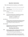
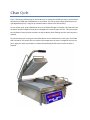
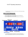
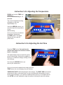
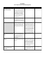
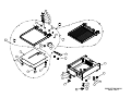
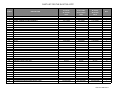
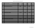
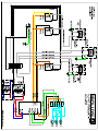
Operations Manual
Model: SL1577
Split Lid Grill
formerly DOUGHPRO. New Name. Same Quality. Superior Service.
proluxe.com
rev8-71713
Operation Instructions
Please read carefully before attempting to use this appliance.
Step 1.
Carefully unpack and clean grill plates with mild soap then sponge clean
with cold water.
Step. 2.
Place in location where it will be used allowing for clearances per the
dimensions indicated.
WARNING! Allow 2” minimum clearance between adjacent equipment and/or
wall areas.
Do not touch hot surfaces.
Step 3.
Plug into proper 3 prong wall outlet. If other appliances are connected
to the same circuit make sure the total load does not exceed maximum
ampacity of the circuit. Electrical information is as follows:
120V/50/60Hz/1 phase/2200W/18.3 Amps
208V/60Hz/1 phase/2800W/13.5 Amps
220V/60Hz/1 phase/2200W/10.0 Amps
Step 4: Warm-up
Energize by turning on the power switch which will illuminate when turned
on. The display flashes and shows left preset timer during warm-up. Preheat temperature time will be 40-50 minutes. When the set point is
reached, the display stops flashing and beeps 3 times.
Step 4: Operation
Simply place product on either side of the grill, close lid and press the
desired pre-set time cycle 10 or 20 seconds. After the time cycle is
finished press it again to reset the time cycle.
Cleaning Instructions
NOTE!
Always turn off power and allow to cool down before attempting to clean.
Never submerge grill in water or other liquid nor use mineral spirits
or other flammable material to clean this appliance.
!Never use ice to cool down grill, warranty will be void!
Clean stainless steel and griddle surfaces with soap and water using a
soft, clean cloth periodically as required, but at least once daily. Never
use harsh abrasives. Use only non-abrasive scouring pads when required.
Clean Cycle
275°F is the factory default temp for the CLEAN cycle. To change the CLEAN cycle temp, simultaneously
hold down the TEMP and CLEAN buttons for 15 seconds. The current temp setting will display on the
right digital display only. Using the up or down arrows to adjust to the desired temp.
To start a clean cycle, push CLEAN button once so the CLEAN LED light is turned on. All preset LED’s are
turned off, and the temperature set point is changed to the clean set point of 275°F. This also initiates
the cool down to clean set point condition as well the display starts flashing until the clean set point is
reached.
To stop the clean cycle, simply press the CLEAN button once to deactivate the clean cycle. The CLEAN
LED is turned off, the preset LED’s are restored, the temperature set point is changed to the main set
point. Again, the warm-up condition is initiated and the display flashes until the cook set point is
reached.
SL1577 Operating Instructions:
1. Press desired time to start the time cycle. After the cycle is finished, press it again to
reset the time cycle
HOW TO FIND TEMPERATURE
1. To find the temperature of the UPPER PLATENS:
Press the TEMPERATURE button and the ARROW UP button at the same time.
2. To find the temperature of the LOWER PLATENS:
Press the TEMPERATURE button and the ARROW DOWN button at the same time
*
* 275° is the factory default temp for the CLEAN cycle. To change the CLEAN cycle temp,
simultaneously hold down the TEMP and CLEAN buttons for 15 seconds. The current temp setting will
display on the right digital display only. Using the up or down arrows to adjust to the desired temp.
Instruction’s for Adjusting the Temperature
PRESS and hold the TEMP and
ARROW up
buttons simultaneously for 15
seconds.
The current temperature setting
will display on the right
digital display only.
Using the ARROW buttons, you
may now adjust the temperature
to your
desired setting.
Once you have set your desired
temperature simply push
the TEMP button. The digital
displays will now read the
preset times.
Instruction’s for Adjusting the Set-Time
Press the TEMP button first and then the
desired timer button and continue to hold
both for 5 seconds.
The digital displays will now read their preset
times as shown here. Each side is capable of
having up to 4 different settings, making a total
of 8 set-times.
Now using the ARROW buttons you
can set your desired time.
Once you have set the desired time simply press the
TEMP button, the unit will display the new set-time.
*IMPORTANT NOTE: When adjusting the time settings, The RIGHT SIDE time buttons
control the left side, so the same time you set on the right will automatically be set to
the left side accordingly. If you desire an additional set of times you can adjust the left
side AFTER you have adjusted the right side without effecting the right side settings.
DOUGHPRO
SL1577 Split Lid Grill Trouble Shooting Guide
Symptom
Power Button on Control face is
depressed but doesn’t turn on.
Probable Cause
Power Cord is not plugged in.
Circuit Breaker is tripped off in the
site's breaker box
Digital Controller's LED's are
scrambled or randomly irratic
Digital Controller is constantly
Beeping No heat on either on left
right Upper, or Lower Platen.
Depress Temp. While depressing
Temp., depress either up or down
arrow to locate error
message,"PROB" (zone 1, Lower
Platen, zone 2 Left Upper Platen,
zone 3, right Upper Platen.) . If
occurred when depressing the up
arrow indicates either the left or
right Upper Platen has the open
sensor or probe. same goes for the
down arrow indicating Lower Platen.
Transformer has taken a electrical
surge and is damaged
Check voltage on the secondary side
of the Transformer. If you read
12VDC then you are receiving voltage
to the Controller.
Possibly blown Fuse
Possibly a componet on the Digital
Controller is damaged
Possibly control needs to reset
Parts List Ref. #
___
Replace Controller. Controller
should be on once the power button
is depressed.
A8
Check fuse and repace if necessary
Replace the Digital Controller.
While unit is on (controller lit up)
Unplug unit, wait for 1 min. then
plug machine on and depress power
button.
Sensor in one of two zones lost it's
Disconnect prob and check for
continuity. Depress Temp. While
continuity (by using Ohm Meter) and
depressing Temp., depress either up replace. Do not cut and splice new
or down arrow to locate error
sensor. Install new 2000 ohm RTD
message,"PROB" (zone 1, Lower
sensor to under side of Heat Platen
Platen, zone 2 Left Upper Platen,
and reconnect to Controller. Upper
zone 3, right Upper Platen.) . If
left and right sensor for replacement
occurred when depressing the up
on upper platens, Lower Platen
arrow indicates either the left or right sensor for replacement for Lower
Upper Platen has the open sensor or Platen.
probe. same goes for the down
arrow indicating Lower Platen
Digital Controller is beeper chirping
and is over heating.
The Mechanical Relay on the
switched side is not opening to
regulate temperture. Same as above,
hold Temp button then depress
either the down or up arrow (zone 1,
Lower Platen, zone 2 Left Upper
Platen, zone 3, right Upper Platen.)
which ever zone is the problem, you
will see RLY indicating the damage (in
closed position) .
One of the three Heater Platens not The offset function in the Controller's
close to set point.
setting needs to be adjusted to
achieve proper shade of toast.
Beeper not functioning
Action to be Taken
Plug power cord into wall 's
receptacle and depress power
button on controller
Reset circuit breaker that the Grill is
plugged into. Depress Power Button
to turn on.
Replace Transformer
Beeper has failing.
___
18
# 98
# A8
___
# 22
# 46
Replace the Mechanical Relay.
#15
Call Doughpro (800) 624-6717 for
instructions. This information must
not to be given to operators of the
SL1577. They may get confused and
cause further temperature
discrepancies.
Replace Controller board
____
# A8
DOUGHPRO
SL1577 Split Lid Grill Trouble Shooting Guide
Symptom
Either Heater Platen is not Heating
but the Digital Controller is on and
appears to be functioning.
Probable Cause
Action to be Taken
If the Mechanical Relay (s) on the coil Replace Mechanical Relay.
side are receiving 12vdc indicates the
Controller is functioning properly. On
the switching side of the relay, is the
rated voltage for the Model(120,208,
or 220~AC) going to the heater in
question? If there is no voltage on
the to the switching side of the relay
to the heaters, the Relay is not
working properly
Heater Platen overheating
The mechanical Relay may be stuck in Replace Mechanical Relay.
the closed position (zone 1, Lower
Platen #1 labeled on this relay, zone
2, left upper and zone 3, right upper).
# 15
If you are receiving 12vdc on the coil
of the relay, the Controller is properly
functioning thus maybe you have a
break in the wire to the heater (s) or
the Heater Platen lost it's continuity
#15
One of the Heater's embedded into
to the Heated Aluminum Platen may
have lost Continuity. With use of a
Ohm Meter a condinuity check must
check at the cold pins of the heater
(where the heater wire is brazed at
the cold pin. This will eliminate any
other failue before the the heater
element validating the loss off
condinuity at the source (Heater
Element). If so, either the Upper left
(zone 2), right (zone 3) or Lower,
Reconnect the pin and the retaining
E-Clip.
Parts List Ref. #
# 15
Parallel Lever not attached either in
the rear out on the Upper Heater
Platen. Check to see if Parallel leveler
is connected on both sides. The
retaining clip attached to pin may
have come off.
Upper Platen falling down or lost It's Possibly the Springs (2, one for each Remove rear panel and adjust the
retension .
Upper Heater Platen has lost some
retaining collars on shaft by winding
retension.
spring tighter. There are mutlple set
screws that need to be loosened in
order to wind the spring tighter.
Once achieving proper tension be
sure to tighten all set screws so that
tension isn't lost again.
# 25
If one heating zone is not reaching
setpoint and another heater is
overheating
___
Either Upper Heater not coming
down parallel to the Lower Heater
Platen.
Sensors maybe crossed
Make sure each sensor is connected
to it's prospective postion on the
terminal block which in turn to the
Controller.
___
72
67
7
86
87
31
29
73
A2P
29
14
A2
A1P
A1
50
46
74
5
4
95
3
96
7
1
6
7
83
42
69
9
8
69
83
42
83
8
69
42
8
EXPSL1577 RB 100314
PAGE 1 OF 3
38
37
40
36
26
38
41
27
43
34
39
10
60
29
37
71
74
24
50
38
23
11
29
25
22
41
29
28
11
43
35
31
27
25
33
28
A3P
60
74
29
31
50
22
11
71
74
29
29
50
25
22
74
30
11
A3
25
50
33
11
32
22
A4
A4P
EXPSL1577 RB 100314
PAGE 2 OF 3
A5
64
55
A6
D
61
28
59
C
77
56
62
64
57
A6P
52
25
53
16
65
25
78
68
85
78
A5P
75
51
16
80 94
78
56
57
54
77
58
70
28
75
18
59
78
88
51
A8
48
76
78
85
A7
98
49
68
78
17
15
89
78
89
79
19
81
88
54
58
47
91
78
92
45
66
93
91
92
93
13
90
93
92
91
92
44
16
EXPSL1577 RB 100314
PAGE 3 OF 3
PART LIST FOR THE SL1577/SL1577P
ITEM #
1
3
4
5
6
7
8
9
10
11
12
13
14
15
16
17
18
19
22
23
24
25
26
27
28
29
30
31
32
33
34
35
36
37
38
39
40
DESCRIPTION
LOWER WRAP AROUND SHROUD ASSEMBLY
LOWER PLATEN INSULATION
COVER, LOWER PLATEN ASSEMBLY
SCREW, SET 5/16-18 X 1/2
SCREW, SET 3/8-16 X1-3/4
GREEN INSULATION WASHER
HEX NUT 3/8-16
STRAIN FELIEF
SCREW, SET 3/8-16 x 1
SCREW, SET 3/8-16 x 1/2
FUSE HOLDER 1 AMP
FUSE BUSS 1 AMP
PIN, BACK STOP
RELAY
SCREW, PAN HEAD PHILLIPS 8-32 x 3/8 STAINLESS STEEL
4 STAGE TERMINAL BLOCK DOUBLE
TRANSFORMER
4 STAGE TERMINAL BLOCK SINGLE
RTD SENSOR
GROMMET 5/16 x 1/2
CLEVIS ASSEMBLY LEFT HAND
E-CLIP, RETAINING RING
HANDLE LEFT ASSEMBLY
SCREW, SOCKET HEAD 5/16-18 x 3/4
WASHER, SPLIT LOCK 5/16
BUSHING TEFLON 1 LONG
CLEVIS ASSEMBLY RIGHT HAND
FLANGED BUSHING TEFLON 1/2 LONG
HANDLE RIGHT ASSEMBLY
HANDLE GRIP
TUBING PAD
SPRING, DETENT 1-1/2 LONG
PLUNGER ASSEMBLY
HANDLE SPRING ADJUSTING COLLAR
SCREW SET KNURLED CUP POINT 5/16-18 X 3/8
COUNTER BALANCE SPRING RIGHT HAND
COUNTER BALANCE SPRING LEFT HAND
MODEL
SL1577A/
SL1577PA
MODEL
SL1577CEC/
SL1577PCEC
MODEL
SL1577E/
SL1577PE
120 V
110115501
110115542
110115506
SST5161812
SST3816134
C4401
NH3816
1106546468
SST38161
SST381612
MPPF708
MPPF701R
110115543
110942520
SP83238S
6014
11096975
6994
1108881101
110115554
110115503
LCC3478
110115522
SSH5161834
WL516
110115541
110115504
110115563
110115521
110901168
110115531
110115555
110115544
110115528
SST5161838KN
1101023154R
1101023154L
220V
110115501
110115542
110115506
SST5161812
SST3816134
C4401
NH3816
1106546468
SST38161
SST381612
MPPF708
MPPF701R
110115543
110942520
SP83238S
6014
11096975
6994
1108881101
110115554
110115503
LCC3478
110115522
SSH5161834
WL516
110115541
110115504
110115563
110115521
110901168
110115531
110115555
110115544
110115528
SST5161838KN
1101023154R
1101023154L
208 V
110115501
110115542
110115506
SST5161812
SST3816134
C4401
NH3816
1106546468
SST38161
SST381612
MPPF708
MPPF701R
110115543
110942520
SP83238S
6014
11096975
6994
1108881101
110115554
110115503
LCC3478
110115522
SSH5161834
WL516
110115541
110115504
110115563
110115521
110901168
110115531
110115555
110115544
110115528
SST5161838KN
1101023154R
1101023154L
QTY.
1
1
1
1
4
10
4
1
2
4
1
1
2
3
7
1
1
1
2
2
1
4
1
6
10
6
1
2
1
2
2
2
2
2
12
1
1
PLSL1577 RB 100314
PART LIST FOR THE SL1577/SL1577P
ITEM #
41
42
43
44
45
46
47
48
49
50
51
52
53
54
55
56
57
58
59
60
61
62
64
65
66
67
68
69
70
71
72
73
74
75
76
77
78
DESCRIPTION
COLLAR HOLDER
FEET, RUBBER 3/4
BUSHING TEFLON 3/4 LONG
GREASE TRAY
OVERLAY
RTD SENSOR
INSTRUMENT HOUSING ASSEMBLY
NYLON SPACER 1/4 x .141 x 9/32
DIGITAL CONTROL
WASHER, SAE #6
NUT, HEX 6-32
INSULATION UPPER PLATEN LEFT HAND
INSULATION UPPER PLATEN RIGHT HAND
TOP LINK
WIRE HARNESS
UPPER LEVELING BRACKET
UPPERLEVELING SHIM
PIN, PIVOT FRONT
BOLT, HEX 5/16-18 X 1 STAINLESS STEEL
WASHER, CUT 5/16
SHROUD, LEFT ASSEMBLY
SHROUD, RIGHT ASSEMBLY
SCREW, PAN HEAD PHILLIPS 10-24X3/8 STAINLESS STEEL
BACK COVER
POWER CORD
SHIM, LOWER PLATEN
PIN PIVOT BACK
WASHER, SPLIT LOCK 3/8
TRANSFORMER INSULATION
SHIM, CLEVIS
BOLT, HEX 1/4-20 X 1
NUT, SERRATED FLANGED HEX 1/4-20
SCREW, PAN HEAD, PHILLIPS 6-32 X 1/4
SCREW, PAN HEAD, PHILLIPS 8-32 x 1-1/2 STAINLESS STEEL
WASHER, STEEL
WASHER, INTERNAL TOOTH LOCK 5/16
RETAINING RING
MODEL
SL1577A/
SL1577PA
MODEL
SL1577CEC/
SL1577PCEC
MODEL
SL1577E/
SL1577PE
120 V
110115530
11016546469
110113441
110115505
OSL1577
1108881102
110115511
11090109
1101041052
WSAE6
NH632
110888251L
110888251R
110115508
1101101050
110115510
110115557
11017088865
BH516181S
WC516
11016546454
11016546455
SP102438S
110115562
1101591174
11060420
11017088866
WL38
1101159180
11060421
BH14201
NHSF1420
SP63214
SP832112S
311150019
WLIT516
11017088867
220V
110115530
11016546469
110113441
110115505
OSL1577
1108881102
110115511
11090109
1101041052
WSAE6
NH632
110888251L
110888251R
110115508
1101101050
110115510
110115557
11017088865
BH516181S
WC516
11016546454
11016546455
SP102438S
110115562
MPPW202
11060420
11017088866
WL38
1101159180
11060421
BH14201
NHSF1420
SP63214
SP832112S
311150019
WLIT516
11017088867
208 V
110115530
11016546469
110113441
110115505
OSL1577
1108881102
110115511
11090109
1101041052
WSAE6
NH632
110888251L
110888251R
110115508
1101101050
110115510
110115557
11017088865
BH516181S
WC516
11016546454
11016546455
SP102438S
110115562
1101217175
11060420
11017088866
WL38
1101159180
11060421
BH14201
NHSF1420
SP63214
SP832112S
311150019
WLIT516
11017088867
QTY.
2
4
2
1
1
1
1
6
1
9
18
1
1
2
1
2
2
2
4
6
1
1
12
1
1
1
2
4
1
2
2
2
3
2
6
4
8
PLSL1577 RB 100314
PART LIST FOR THE SL1577/SL1577P
ITEM #
79
80
81
83
85
86
87
88
89
90
91
92
93
94
95
96
97
98
A1
A1P
A2
A2P
A3
A3P
A4
A4P
A5
A5P
A6
A6P
A7
A8
DESCRIPTION
MARKER STRIP, #4 SINGLE
MARKER STRIP, #4 DOUBLE
SCREW, PAN HEAD PHILLIPS 2-56 X 1/4
WASHER, SAE 3/8
WASHER, INTERNAL TOOTH LOCK #6
WASHER, SAE 1/4
WASHER, SPLIT LOCK 1/4
SCREW, PAN HEAD PHILLIPS 6-32 x 3/8
SCREW, PAN HEAD PHILLIPS 6-32 x 5/8
SCREW, PAN HEAD PHILLIPS 8-32X1
NUT, HEX 8-32
WASHER, SAE #8
WASHER, INTERNAL TOOTH LOCK #8
MOUNTING BRACKET ASSEMBLY
COVER, HEATER ELEMENT
SCREW, PAN HEAD PHILLIPS 6-32 X1/4 STAINLESS STEEL
MANUAL SL1577
GASKET, PUSH BUTTON CONTROLLER
LOWER PLATEN WITH WIRING
LOWER PLATEN PANINI WITH WIRING
LOWER PLATEN ASSEMBLY
LOWER PLATEN PANINI ASSEMBLY
UPPER PLATEN LEFT HAND WITH WIRING
UPPER PLATEN PANINI LEFT HAND WITH WIRING
UPPER PLATEN RIGHT HAND WITH WIRING
UPPER PLATEN PANINI RIGHT HAND WITH WIRING
UPPER PLATEN LEFT HAND ASSEMBLY
UPPER PLATEN PANINI LEFT HAND ASSEMBLY
UPPER PLATEN RIGHT HAND ASSEMBLY
UPPER PLATEN PANINI RIGH HAND ASSEMBLY
KITTED, CONTROLLER TEMPERATIRE, WITH INSTRUCTIONS
KITTED, CONTROLLER TEMPERATURE ASSEMBLY
MODEL
SL1577A/
SL1577PA
MODEL
SL1577CEC/
SL1577PCEC
MODEL
SL1577E/
SL1577PE
120 V
MS6994
MS6014
SP25614
WSAE38
WLIT6
WSAE14
WL14
SP63238
SP63258
SP8321
NH832
WSAE8
WLIT8
110115559
110115564
SP63214ST
MSL1577
11017088803
1101155207
1101155207P
1101155116
1101155116P
1101155201
1101591201L
1101155204
1101591204R
1101155110
1101591110L
1101155113
1101591113R
1101041052K
110104152K
220V
MS6994
MS6014
SP25614
WSAE38
WLIT6
WSAE14
WL14
SP63238
SP63258
SP8321
NH832
WSAE8
WLIT8
110115559
110115564
SP63214ST
MSL1577
11017088803
1101155208
1101155308P
1101155117
1101155317P
1101155202
1101155302L
1101155205
1101155305R
1101155111
1101155311L
1101155114
1101155314R
1101041052K
110104152K
208 V
MS6994
MS6014
SP25614
WSAE38
WLIT6
WSAE14
WL14
SP63238
SP63258
SP8321
NH832
WSAE8
WLIT8
110115559
110115564
SP63214ST
MSL1577
11017088803
1101155209
1101155309P
1101155118
1101155318P
1101155203
1101155303L
1101155206
1101155306R
1101155112
1101155312L
1101155115
1101155315R
1101041052K
110104152K
QTY.
1
1
1
4
18
2
2
8
4
1
3
4
3
1
1
2
1
4
1
1
1
1
1
1
1
1
1
1
1
1
1
1
PLSL1577 RB 100314
PLEASE READ CAREFULLY BEFORE ATTEMPTING TO USE
THIS APPLIANCE.
LIMITED MACHINE WARRANTY
WHAT IS COVERED
Proluxe warrants the SL1577, from manufacturing defects in workmanship and material sold within
the domestic United States.
HOW LONG DOES THE COVERAGE LAST
One year warranty for parts and labor.
WHAT WE WILL DO
We will repair or replace the defective SL1577 on normal warranty one year parts and labor. The
heating elements on the upper and lower platen only; will be replaced by next day air service;
under the normal one year warranty. Such repair or replacement will be at the expense of Proluxe
on under the normal one year warranty.
HOW TO GET SERVICE
Contact our Factory to obtain warranty service. Proluxe must issue a return authorization
number, and call tag, or find the name and location of a Factory Authorized Service Center
nearest you. When calling for service, please furnish the model number, serial number, and a
description of the problem.
WHAT THIS WARRANTY DOES NOT COVER
THE WARRANTIES PROVIDED BY PROLUXE DO NOT APPLY IN THE FOLLOWING INSTANCES:
•
Damage due to misuse, abuse, alteration, or accident.
•
Improper or unauthorized repairs.
•
Submerged in water.
•
Dropped.
•
Damage in shipment.
•
Equipment exported to foreign countries.
Warranty & Return Policy
Proluxe warrants all products manufactured by it against defects in workmanship or materials from the date of purchase for a period of
(1) year on parts and labor. This warranty applies to only equipment purchased and used in the United States. Warranty period
shall begin when equipment ships and will not exceed 90 days past the original shipment date. Warranty travel shall only
be covered for 60 miles.
ALL WARRANTY SERVICE CALLS MUST BE APPROVED BY PROLUXE. IF THIS PROCEDURE IS NOT FOLLOWED,
WARRANTY SERVICE WILL NOT BE COVERED. WARRANTY SERVICE WILL BE PAID ON STRAIGHT TIME, OVERTIME WILL
NOT BE COVERED.
Exclusions:
1. WOOD / GAS FIRED OVENS: PROLUXE warranty applies to the main body of the oven being steel / refractory and insulation shall
be free from defects in materials and workmanship for a period of four years from the date of purchase. The gas equipment shall be
free from defects in materials and workmanship for a period of one (1) year
from the date of purchase. This warranty excludes the tandoori and home oven. Lifetime warranty against cracks on oven floor.
2. TANDOORI & HOME OVENS: PROLUXE warrants the Tandoori & Home Oven including gas equipment shall be free from defects
in materials and workmanship for a period of one (1) year from the date of purchase.
3. Air compressors are excluded from this warranty, but PROLUXE may act as a warranty expeditor in certain instances regarding
these compressors. The air compressor manufacturer provides a limited warranty
and a copy of this warranty is furnished with all compressors sold by PROLUXE. For prompt handling of compressor warranty claims
the instructions of the compressor manufacturer must be adhered to.
4. Equipment built to special order as well as accessories are not returnable unless defective within the terms of this warranty.
5. In no event shall PROLUXE be liable for consequential damages arising out of the failure of any of its products if operated
improperly or caused by normal wear or damage by operator abuse.
6. BC2325 pedestal warranty disclaimer: Pedestals shall only be covered under warranty if they have been cleaned using the factory
approved cleaning method. cracked or damaged pedestals must be inspected by the factory before warranty is authorized.
Returned Merchandise Policy:
Should it become necessary to return any of the company’s products, the following instructions must be adhered to: First,
contact our customer service department for approval and a return authorization number. Please have the serial number
of your item available at that time. All merchandise must be shipped freight prepaid by customer or service agency.
Subject to the inspection of the product by the company, a restocking charge of 20% of the Net purchased price paid to
PROLUXE will be assessed. Merchandise may not be returned for credit without prior written approval of PROLUXE. Collect shipments
will not be accepted. No returns after 60 days of original shipment date on machines. Purchased parts may not be returned after 30
days.
If upon inspection by PROLUXE or its authorized agent it is determined the equipment has not been used in an appropriate manner,
has been modified, or has not been properly maintained, or has been subject to misuse,
misapplication, neglect, abuse, accident, unauthorized modification, damage during transit, delivery, fire, flood, act or war,
riot or act of God, then this warranty shall be deemed null and void.
Terms & Conditions:
1. Prices indicated in the PRICE LIST are suggested retail prices and are shown in U.S. DOLLARS.
2. Terms of Payment: 1% 10 days, NET 30 days.
3. NEW ACCOUNTS: Satisfactory credit information must be provided before open account status can be extended.
Unless agreed otherwise, all shipments will be made C.O.D., CASH IN ADVANCE.
4. PRICING: Prices, specifications, model numbers, capacities and accessories are subject to change without notice.
5. FREIGHT / ROUTING: Method of shipment will be determined by PROLUXE unless otherwise
advised by PURCHASER.
6. DAMAGED CLAIMS: All merchandise shipped at purchaser’s risk. Inspection must be made by purchaser at time
goods are received. If goods are damaged, the PURCHASER shall request that the agent of the transportation
company make a written notation on the proper shipping documents immediately and then file a claim for damage.
GOODS DAMAGED IN SHIPMENT ARE NOT RETURNABLE.
7. RETURNS: Machines may not be returned after 60 days. Purchased parts may not be returned after 30 days. A
restocking fee of 20% will be assessed on non-warranty returns.
8. TAXES: Prices indicated herein DO NOT include State, Federal, Local or foreign taxes or duties, nor do they include
fees, permits, insurance or other levies, all of which are the responsibility of the purchaser.
9. All orders are subject to acceptance by PROLUXE.
10. Possession of this price list shall not be considered an offer to sell.