1
Preface
No single troubleshooting resource can anticipate every possible glitch that can be encountered in
internetworks. But any significant contribution that can be made toward preventing connectivity
blockages is a step in the right direction. We hope that this publication contributes to the body of
knowledge that makes networks more manageable.
Audience
Internetworking Troubleshooting Handbook is intended for network administrators who are
responsible for troubleshooting internetworks that implement Cisco products and Cisco-supported
protocols.
Administrators should have hands-on experience in configuring, administering, and troubleshooting
a network, should know how to configure routers, switches and bridges, and should be familiar with
the protocols and media that their hardware has been configured to support. Awareness of the basic
topology of their network is also essential.
Document Organization
The Internetworking Troubleshooting Handbook provides the information necessary to troubleshoot
many problems commonly encountered in internetworks using Cisco hardware and software
products. This publication consists of the following six parts:
•
The chapters in Part 1, “Introduction to Troubleshooting,” provide an introduction to
troubleshooting techniques and an overview of common troubleshooting tools.
•
The chapters in Part 2, “Hardware, Booting, and Media Problems,” provide information for
troubleshooting hardware problems, LAN media problems, and booting (system initialization)
problems.
•
The chapters in Part 3, “Troubleshooting Desktop and Entreprise Routing Protocols,” provide
information on troubleshooting common connectivity and performance problems in TCP/IP,
Novell IPX, AppleTalk, IBM, and other widely-implemented network environments.
•
The chapters in Part 4, “Troubleshooting Serial Lines and WAN Connections,” provide
information on troubleshooting problems that commonly occur on serial lines and WAN links
such as ISDN, Frame Relay, and X.25.
•
The chapters in Part 5, “Troubleshooting Bridging and Switching Environments,” provide
information on troubleshooting problems commonly encountered in ATM switching, LAN
switching, and bridging environments.
Preface xvii
Using This Publication
•
The chapters in Part 6, “Troubleshooting Other Internetwork Problems,” provide information on
troubleshooting CiscoWorks installations, and on troubleshooting security implementations,
including TACACS troubleshooting and password recovery.
•
Appendixes provide supplemental troubleshooting information, including information on
creating core dumps, memory maps for different Cisco routers, technical support information,
and a list of references and recommended reading. In addition, at the end of the book are several
perforated troubleshooting worksheets to assist you in gathering information when problems
occur.
Using This Publication
This publication is designed to provide users with the information needed to troubleshoot common
problems encountered in Cisco-based internetworks. Most chapters focus on describing symptoms,
identifying their causes, and suggesting specific actions to resolve the problem. Some material
describes preventative measures or tips for identifying problems by interpreting command output.
Document Conventions
Our software and hardware documentation uses the following conventions:
•
The symbol ^ represents the key labeled Control.
For example, ^D means hold down the Control key while you press the D key.
•
A string is defined as a nonquoted set of characters. For example, when setting up a community
string for SNMP to “public,” do not use quotes around the string, or the string will include the
quotation marks.
Command descriptions use these conventions:
•
Examples that contain system prompts denote interactive sessions, indicating that the user enters
commands at the prompt. The system prompt indicates the current command mode. For example,
the prompt router(config)# indicates global configuration mode.
•
•
•
•
Commands and keywords are in boldface font.
Arguments for which you supply values are in italic font.
Elements in square brackets ([ ]) are optional.
Alternative but required keywords are grouped in braces ({ }) and separated by vertical bars (|).
Examples use these conventions:
•
•
•
•
•
•
Terminal sessions and information the system displays are in screen font.
Information you enter is in boldface screen font.
Nonprinting characters, such as passwords, are in angle brackets (< >).
Default responses to system prompts are in square brackets ([ ]).
Exclamation points (!) at the beginning of a line indicate a comment line.
When part of the command output has been omitted (to conserve space), the deleted output is
indicated with italicized brackets and ellipsis ([...])
Note This is a special paragraph that means reader take note. It usually refers to helpful
suggestions, the writer’s assumptions, or reference to materials not contained in this manual.
xviii
Book Title
C H A P TER
1
Troubleshooting Overview
Internetworks come in a variety of topologies and levels of complexity—from single-protocol,
point-to-point links connecting cross-town campuses, to highly meshed, large-scale wide-area
networks (WANs) traversing multiple time zones and international boundaries. The industry trend is
toward increasingly complex environments, involving multiple media types, multiple protocols, and
often interconnection to “unknown” networks. Unknown networks may be defined as a transit
network belonging to a Internet service provider (ISP) or a telco that interconnects your private
networks. In these unknown networks, you do not have control of such factors as delay, media types,
or vendor hardware.
More complex network environments mean that the potential for connectivity and performance
problems in internetworks is high, and the source of problems is often elusive.The keys to
maintaining a problem-free network environment, as well as maintaining the ability to isolate and
fix a network fault quickly, are documentation, planning, and communication. This requires a
framework of procedures and personnel to be in place long before any network changes take place.
The goal of this book is to help you isolate and resolve the most common connectivity and
performance problems in your network environment.
Symptoms, Problems, and Solutions
Failures in internetworks are characterized by certain symptoms. These symptoms might be general
(such as clients being unable to access specific servers) or more specific (routes not in routing table).
Each symptom can be traced to one or more problems or causes by using specific troubleshooting
tools and techniques. Once identified, each problem can be remedied by implementing a solution
consisting of a series of actions.
This book describes how to define symptoms, identify problems, and implement solutions in generic
environments. You should always apply the specific context in which you are troubleshooting to
determine how to detect symptoms and diagnose problems for your specific environment.
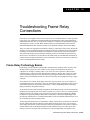
General Problem-Solving Model
When you’re troubleshooting a network environment, a systematic approach works best. Define the
specific symptoms, identify all potential problems that could be causing the symptoms, and then
systematically eliminate each potential problem (from most likely to least likely) until the symptoms
disappear.
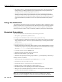
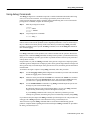
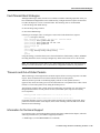
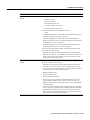
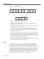
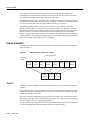
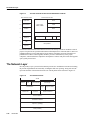
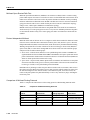
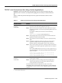
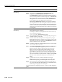
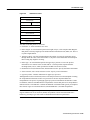
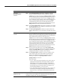
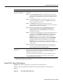
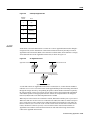
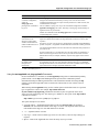
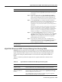
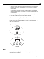
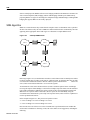
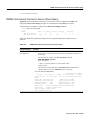
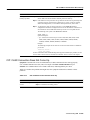
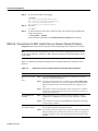
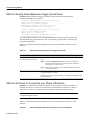
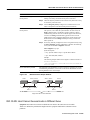
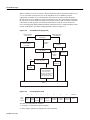
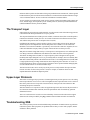
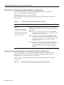
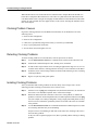
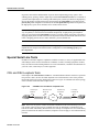
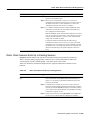
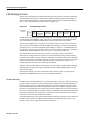
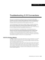
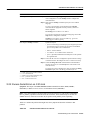
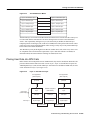
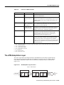
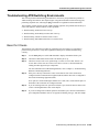
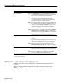
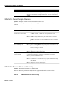
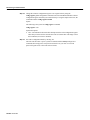
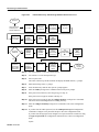
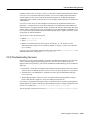
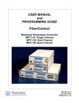
Figure 1-1 illustrates the process flow for the general problem-solving model. This process flow is
not a rigid outline for troubleshooting an internetwork; it is a foundation from which you can build
a problem-solving process to suit your particular environment.
Troubleshooting Overview 1-3
General Problem-Solving Model
Figure 1-1
General Problem-Solving Model
Define problem
Gather facts
Consider possibilities based on facts
Create action plan
Implement action plan
Observe results
(If symptoms stop…)
(If symptoms persist…)
Repeat process
Problem resolved; terminate process
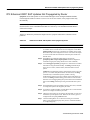
The following steps detail the problem-solving process outlined in Figure 1-1:
Step 1
When analyzing a network problem, make a clear problem statement. You should define
the problem in terms of a set of symptoms and potential causes.
To properly analyze the problem, identify the general symptoms and then ascertain what
kinds of problems (causes) could result in these symptoms. For example, hosts might not
be responding to service requests from clients (a symptom). Possible causes might
include a misconfigured host, bad interface cards, or missing router configuration
commands.
Step 2
Gather the facts you need to help isolate possible causes.
Ask questions of affected users, network administrators, managers, and other key people.
Collect information from sources such as network management systems, protocol
analyzer traces, output from router diagnostic commands, or software release notes.
Step 3
Consider possible problems based on the facts you gathered. Using the facts you
gathered, you can eliminate some of the potential problems from your list.
Depending on the data, you might, for example, be able to eliminate hardware as a
problem, so that you can focus on software problems. At every opportunity, try to narrow
the number of potential problems so that you can create an efficient plan of action.
Step 4
Create an action plan based on the remaining potential problems. Begin with the most
likely problem and devise a plan in which only one variable is manipulated.
Changing only one variable at a time allows you to reproduce a given solution to a specific
problem. If you alter more than one variable simultaneously, you might solve the
problem, but identifying the specific change that eliminated the symptom becomes far
more difficult and will not help you solve the same problem if it occurs in the future.
Step 5
1-4
Book Title
Implement the action plan, performing each step carefully while testing to see whether
the symptom disappears.
Preparing for Network Failure
Step 6
Whenever you change a variable, be sure to gather results. Generally, you should use the
same method of gathering facts that you used in Step 2 (that is, working with the key
people affected in conjunction with utilizing your diagnostic tools).
Step 7
Analyze the results to determine whether the problem has been resolved. If it has, then
the process is complete.
Step 8
If the problem has not been resolved, you must create an action plan based on the next
most likely problem in your list. Return to Step 4, change one variable at a time, and
reiterate the process until the problem is solved.
Note If you exhaust all the common causes and actions (either those outlined in this book or ones
that you have identified for your environment), you should contact your Cisco technical support
representative.
Preparing for Network Failure
It is always easier to recover from a network failure if you are prepared ahead of time. Possibly the
most important requirement in any network environment is to have current and accurate information
about that network available to the network support personnel at all times. Only with complete
information can intelligent decisions be made about network change, and only with complete
information can troubleshooting be done as quickly and easily as possible. During the process of
troubleshooting the network that it is most critical to ensure that this documentation is kept
up-to-date.
To determine whether you are prepared for a network failure, answer the following questions:
•
Do you have an accurate physical and logical map of your internetwork?
Does your organization or department have an up-to-date internetwork map that outlines the
physical location of all the devices on the network and how they are connected, as well as a
logical map of network addresses, network numbers, subnetworks, and so forth?
•
Do you have a list of all network protocols implemented in your network?
For each of the protocols implemented, do you have a list of the network numbers, subnetworks,
zones, areas, and so on that are associated with them?
•
Do you know which protocols are being routed?
For each routed protocol, do you have correct, up-to-date router configuration?
•
Do you know which protocols are being bridged?
Are there any filters configured in any bridges, and do you have a copy of these configurations?
•
Do you know all the points of contact to external networks, including any connections to the
Internet?
For each external network connection, do you know what routing protocol is being used?
•
Do you have an established baseline for your network?
Has your organization documented normal network behavior and performance at different times
of the day so that you can compare the current problems with a baseline?
If you can answer yes to all questions, you will be able to recover from a failure more quickly and
more easily than if you are not prepared.
Troubleshooting Overview 1-5
Preparing for Network Failure
1-6
Book Title
C H A P TER
2
Troubleshooting Tools
This chapter presents information about the wide variety of tools available to assist you in
troubleshooting your internetwork, including information on using router diagnostic commands,
using Cisco network management tools, and third-party troubleshooting tools.
Using Router Diagnostic Commands
Cisco routers provide numerous integrated commands to assist you in monitoring and
troubleshooting your internetwork. The following sections describe the basic use of these
commands:
•
The show commands help monitor installation behavior and normal network behavior, as well as
isolate problem areas.
•
•
•
The debug commands assist in the isolation of protocol and configuration problems.
The ping commands help determine connectivity between devices on your network.
The trace commands provide a method of determining the route by which packets reach their
destination from one device to another.
Using show Commands
The show commands are powerful monitoring and troubleshooting tools. You can use the show
commands to perform a variety of functions:
•
•
•
•
•
Monitor router behavior during initial installation
Monitor normal network operation
Isolate problem interfaces, nodes, media, or applications
Determine when a network is congested
Determine the status of servers, clients, or other neighbors
Following are some of the most commonly used show commands:
•
show interfaces—Use the show interfaces exec command to display statistics for all interfaces
configured on the router or access server. The resulting output varies, depending on the network
for which an interface has been configured.
Some of the more frequently used show interfaces commands include the following:
— show interfaces ethernet
— show interfaces tokenring
Troubleshooting Tools 2-7
Using Router Diagnostic Commands
— show interfaces fddi
— show interfaces atm
— show interfaces serial
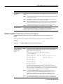
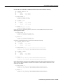
— show controllers—This command displays statistics for interface card controllers. For
example, the show controllers mci command provides the following fields:
MCI 0, controller type 1.1, microcode version 1.8
128 Kbytes of main memory, 4 Kbytes cache memory
22 system TX buffers, largest buffer size 1520
Restarts: 0 line down, 0 hung output, 0 controller error
Interface 0 is Ethernet0, station address 0000.0c00.d4a6
15 total RX buffers, 11 buffer TX queue limit, buffer size
Transmitter delay is 0 microseconds
Interface 1 is Serial0, electrical interface is V.35 DTE
15 total RX buffers, 11 buffer TX queue limit, buffer size
Transmitter delay is 0 microseconds
High speed synchronous serial interface
Interface 2 is Ethernet1, station address aa00.0400.3be4
15 total RX buffers, 11 buffer TX queue limit, buffer size
Transmitter delay is 0 microseconds
Interface 3 is Serial1, electrical interface is V.35 DCE
15 total RX buffers, 11 buffer TX queue limit, buffer size
Transmitter delay is 0 microseconds
High speed synchronous serial interface
1520
1520
1520
1520
Some of the most frequently used show controllers commands include the following:
— show controllers token
— show controllers FDDI
— show controllers LEX
— show controllers ethernet
— show controllers E1
— show controllers MCI
— show controllers cxbus
— show controllers t1
— show running-config— Displays the router configuration currently running
— show startup-config—Displays the router configuration stored in nonvolatile RAM
(NVRAM)
— show flash—Group of commands that display the layout and contents of flash memory
— show buffers—Displays statistics for the buffer pools on the router
— show memory—Shows statistics about the router’s memory, including free pool statistics
— show processes—Displays information about the active processes on the router
— show stacks—Displays information about the stack utilization of processes and interrupt
routines, as well as the reason for the last system reboot
— show version—Displays the configuration of the system hardware, the software version, the
names and sources of configuration files, and the boot images
There are hundreds of other show commands available. For details on using and interpreting the
output of specific show commands, refer to the Cisco Internetwork Operating System (IOS)
command references.
2-8
Book Title
Using debug Commands
Using debug Commands
The debug privileged exec commands can provide a wealth of information about the traffic being
seen (or not seen) on an interface, error messages generated by nodes on the network,
protocol-specific diagnostic packets, and other useful troubleshooting data. To access and list the
privileged exec commands, complete the following tasks:
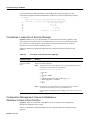
Step 1
Enter the privileged exec mode:
Command:
Router> enable
Password: XXXXXX
Router#
Step 2
List privileged exec commands:
Router# debug ?
Note Exercise care when using debug commands. Many debug commands are processor intensive
and can cause serious network problems (such as degraded performance or loss of connectivity) if
they are enabled on an already heavily loaded router. When you finish using a debug command,
remember to disable it with its specific no debug command (or use the no debug all command to
turn off all debugging).
Use debug commands to isolate problems, not to monitor normal network operation. Because the
high processor overhead of debug commands can disrupt router operation, you should use them only
when you are looking for specific types of traffic or problems and have narrowed your problems to
a likely subset of causes.
Output formats vary with each debug command. Some generate a single line of output per packet,
and others generate multiple lines of output per packet. Some generate large amounts of output, and
others generate only occasional output. Some generate lines of text, and others generate information
in field format.
To minimize the negative impact of using debug commands, follow this procedure:
Step 1
Use the no logging console global configuration command on your router. This command
disables all logging to the console terminal.
Step 2
Telnet to a router port and enter the enable exec command. The enable exec command
will place the router in the privileged exec mode. After entering the enable password,
you will receive a prompt that will consist of the router name with a # symbol.
Step 3
Use the terminal monitor command to copy debug command output and system error
messages to your current terminal display.
By redirecting output to your current terminal display, you can view debug command
output remotely, without being connected through the console port.
If you use debug commands at the console port, character-by-character processor
interrupts are generated, maximizing the processor load already caused by using debug.
If you intend to keep the output of the debug command, spool the output to a file. The procedure for
setting up such a debug output file is described in the Debug Command Reference.
This book refers to specific debug commands that are useful when troubleshooting specific
problems. Complete details regarding the function and output of debug commands are provided in
the Debug Command Reference.
Troubleshooting Tools 2-9
Using Router Diagnostic Commands
In many situations, using third-party diagnostic tools can be more useful and less intrusive than using
debug commands. For more information, see the section “Third-Party Troubleshooting Tools” later
in this chapter.
Using the ping Command
To check host reachability and network connectivity, use the ping exec (user) or privileged exec
command. After you log in to the router or access server, you are automatically in user exec
command mode. The exec commands available at the user level are a subset of those available at the
privileged level. In general, the user exec commands allow you to connect to remote devices, change
terminal settings on a temporary basis, perform basic tests, and list system information. The ping
command can be used to confirm basic network connectivity on AppleTalk, ISO Conectionless
Network Service (CLNS), IP, Novell, Apollo, VINES, DECnet, or XNS networks.
For IP, the ping command sends Internet Control Message Protocol (ICMP) Echo messages. ICMP
is the Internet protocol that reports errors and provides information relevant to IP packet addressing.
If a station receives an ICMP Echo message, it sends an ICMP Echo Reply message back to the
source.
The extended command mode of the ping command permits you to specify the supported IP header
options. This allows the router to perform a more extensive range of test options. To enter ping
extended command mode, enter yes at the extended commands prompt of the ping command.
It is a good idea to use the ping command when the network is functioning properly to see how the
command works under normal conditions and so you have something to compare against when
troubleshooting.
For detailed information on using the ping and extended ping commands, refer to the Cisco IOS
Configuration Fundamentals Command Reference.
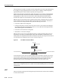
Using the trace Command
The trace user exec command discovers the routes that a router’s packets follow when traveling to
their destinations. The trace privileged exec command permits the supported IP header options to
be specified, allowing the router to perform a more extensive range of test options.
The trace command works by using the error message generated by routers when a datagram
exceeds its time-to-live (TTL) value. First, probe datagrams are sent with a TTL value of 1. This
causes the first router to discard the probe datagrams and send back “time exceeded” error messages.
The trace command then sends several probes and displays the round-trip time for each. After every
third probe, the TTL is increased by one.
Each outgoing packet can result in one of two error messages. A “time exceeded” error message
indicates that an intermediate router has seen and discarded the probe. A “port unreachable” error
message indicates that the destination node has received the probe and discarded it because it could
not deliver the packet to an application. If the timer goes off before a response comes in, trace prints
an asterisk (*).
The trace command terminates when the destination responds, when the maximum TTL is
exceeded, or when the user interrupts the trace with the escape sequence.
As with ping, it is a good idea to use the trace command when the network is functioning properly
to see how the command works under normal conditions and so you have something to compare
against when troubleshooting.
For detailed information on using the trace and extended trace commands, refer to the Cisco IOS
Configuration Fundamentals Command Reference.
2-10
Book Title
Using Cisco Network Management Tools
Using Cisco Network Management Tools
Cisco offers several network management products that provide design, monitoring, and
troubleshooting tools to help you manage your internetwork.
The following three internetwork management tools are useful for troubleshooting internetwork
problems:
•
CiscoWorks internetwork management software, a set of Simple Network Management Protocol
(SNMP)–based tools.
•
The TrafficDirector RMON application, a remote monitoring tool that enables you to gather data,
monitor activity on your network, and find potential problems.
•
The VlanDirector switch management application, a management tool that provides an accurate
picture of your VLANs.
CiscoWorks Internetwork Management Software
CiscoWorks is a series of SNMP-based internetwork management software applications.
CiscoWorks applications are integrated on several popular network management platforms and build
on industry-standard platforms to provide applications for monitoring device status, maintaining
configurations, and troubleshooting problems.
Following are some of the applications included in the CiscoWorks product that are useful for
troubleshooting your internetwork:
•
Device Monitor—Allows the network manager to specify which network devices to monitor for
information about environmental and interface statistics. The configuration includes settings to
specify how often CiscoWorks should check this information and whether to log it in to the Log
Manager application.
•
Health Monitor—Displays information about the status of a device, including buffers, CPU load,
memory available, and protocols and interfaces being used.
•
•
Show Commands—Enable you to view data similar to output from router show exec commands.
•
•
Device Polling—Probes and extracts data about the condition of network devices.
•
Offline Network Analysis—Collects historical network data for offline analysis of performance
trends and traffic patterns.
•
CiscoConnect—Allows you to provide Cisco with debugging information, configurations, and
topology information to speed resolution of network problems.
Path Tool—Displays and analyzes the path between two devices to collect utilization and error
data.
CiscoView—Provides dynamic monitoring and troubleshooting functions, including a graphical
display of Cisco devices, statistics, and comprehensive configuration information.
CiscoWorks implements numerous other applications that are useful for administering, designing,
and monitoring your internetwork. Refer to the Cisco Systems Product Catalog for more
information.
The TrafficDirector RMON Application
The TrafficDirector advanced packet filters let users monitor all seven layers of network traffic.
Using Cisco IOS embedded RMON agents and SwitchProbe standalone probes, managers can view
enterprise-wide network traffic from the link, network, transport, or application layers. The
Troubleshooting Tools 2-11
Third-Party Troubleshooting Tools
TrafficDirector multilayer traffic summary provides a quick, high-level assessment of network
loading and protocol distributions. Network managers then “zoom in” on a specific segment, ring,
switch port, or trunk link and apply real-time analysis and diagnostic tools to view hosts,
conversations, and packet captures.
TrafficDirector threshold monitoring enables users to implement a proactive management
environment. First, thresholds for critical Management Information Base (MIB) variables are set
within the RMON agent. When these thresholds are exceeded, traps are sent to the appropriate
management station to notify the network administrator of an impending problem.
The VlanDirector Switch Management Application
The VlanDirector switch management application simplifies VLAN port assignment and offers
other management capabilities for VLANs. VlanDirector offers the following features for network
administrators:
•
•
•
•
Accurate representation of the physical network for VLAN design and configuration verification
•
•
Quick detection of changes in VLAN status of switch ports
Capability to obtain VLAN configuration information on a specific device or link interface
Discrepancy reports on conflicting configurations
Ability to troubleshoot and identify individual device configurations that are in error with
system-level VLANs
User authentication and write protection security
Third-Party Troubleshooting Tools
In many situations, third-party diagnostic tools can be more useful than commands that are
integrated into the router. For example, enabling a processor-intensive debug command can be
disastrous in an environment experiencing excessively high traffic levels. However, attaching a
network analyzer to the suspect network is less intrusive and is more likely to yield useful
information without interrupting the operation of the router.The following are some typical
third-party troubleshooting tools used for troubleshooting internetworks:
•
Volt-Ohm meters, digital multimeters, and cable testers are useful in testing the physical
connectivity of your cable plant.
•
Time domain reflectors (TDRs) and optical time domain reflectors (OTDRs) are devices that
assist in the location of cable breaks, impedence mismatches, and other physical cable plant
problems.
•
•
Breakout boxes and fox boxes are useful for troubleshooting problems in peripheral interfaces.
Network analyzers such the Network General Sniffer decode problems at all seven OSI layers
and can be identified automatically in real-time, providing a clear view of network activity and
categorizing problems by criticality.
Volt-Ohm Meters, Digital Multimeters, and Cable Testers
Volt-ohm meters and digital multimeters are at the lower end of the spectrum of cable testing tools.
These devices measure parameters such as AC and DC voltage, current, resistance, capacitance, and
cable continuity. They are used to check physical connectivity.
2-12
Book Title
TDRs and OTDRs
Cable testers (scanners) also enable you to check physical connectivity. Cable testers are available
for shielded twisted pair (STP), unshielded twisted pair (UTP), 10BaseT, and coaxial and twinax
cables. A given cable tester might be able to perform any of the following functions:
•
•
•
Test and report on cable conditions, including near-end crosstalk (NEXT), attenuation, and noise
Perform TDR, traffic monitoring, and wire map functions
Display Media Access Control (MAC) layer information about LAN traffic, provide statistics
such as network utilization and packet error rates, and perform limited protocol testing (for
example, TCP/IP tests such as ping)
Similar testing equipment is available for fiber-optic cable. Due to the relatively high cost of this
cable and its installation, fiber-optic cable should be tested both before installation (on-the-reel
testing) and after installation. Continuity testing of the fiber requires either a visible light source or
a reflectometer. Light sources capable of providing light at the three predominant wavelengths,
850 nanometers (nm), 1300 nm, and 1550 nm, are used with power meters that can measure the
same wavelengths and test attenuation and return loss in the fiber.
TDRs and OTDRs
At the top end of the cable testing spectrum are TDRs. These devices can quickly locate open and
short circuits, crimps, kinks, sharp bends, impedance mismatches, and other defects in metallic
cables.
A TDR works by “bouncing” a signal off the end of the cable. Opens, shorts, and other problems
reflect the signal back at different amplitudes, depending on the problem. A TDR measures how
much time it takes for the signal to reflect and calculates the distance to a fault in the cable. TDRs
can also be used to measure the length of a cable. Some TDRs can also calculate the propagation rate
based on a configured cable length.
Fiber-optic measurement is performed by an OTDR. OTDRs can accurately measure the length of
the fiber, locate cable breaks, measure the fiber attenuation, and measure splice or connector losses.
An OTDR can be used to take the “signature” of a particular installation, noting attenuation and
splice losses. This baseline measurement can then be compared with future signatures when a
problem in the system is suspected.
Breakout Boxes, Fox Boxes, and BERTs/BLERTs
Breakout boxes, fox boxes, and bit/block error rate testers (BERTs/BLERTs) are digital interface
testing tools used to measure the digital signals present at PCs, printers, modems, the channel service
unit/digital service unit (CSU/DSU), and other peripheral interfaces. These devices can monitor data
line conditions, analyze and trap data, and diagnose problems common to data communication
systems. Traffic from data terminal equipment (DTE) through data communications equipment
(DCE) can be examined to help isolate problems, identify bit patterns, and ensure that the proper
cabling has been installed. These devices cannot test media signals such as Ethernet, Token Ring, or
FDDI.
Network Monitors
Network monitors continuously track packets crossing a network, providing an accurate picture of
network activity at any moment, or a historical record of network activity over a period of time. They
do not decode the contents of frames. Monitors are useful for baselining, in which the activity on a
network is sampled over a period of time to establish a normal performance profile, or baseline.
Troubleshooting Tools 2-13
Third-Party Troubleshooting Tools
Monitors collect information such as packet sizes, the number of packets, error packets, overall
usage of a connection, the number of hosts and their MAC addresses, and details about
communications between hosts and other devices. This data can be used to create profiles of LAN
traffic as well as to assist in locating traffic overloads, planning for network expansion, detecting
intruders, establishing baseline performance, and distributing traffic more efficiently.
Network Analyzers
A network analyzer (also called a protocol analyzer) decodes the various protocol layers in a
recorded frame and presents them as readable abbreviations or summaries, detailing which layer is
involved (physical, data link, and so forth) and what function each byte or byte content serves.
Most network analyzers can perform many of the following functions:
2-14
Book Title
•
Filter traffic that meets certain criteria so that, for example, all traffic to and from a particular
device can be captured
•
•
•
•
Time stamp captured data
Present protocol layers in an easily readable form
Generate frames and transmit them onto the network
Incorporate an “expert” system in which the analyzer uses a set of rules, combined with
information about the network configuration and operation, to diagnose and solve, or offer
potential solutions to, network problems
C H A P TER
3
Troubleshooting Hardware and
Booting Problems
This chapter provides procedures for troubleshooting hardware and booting problems. Although it
provides specific procedures for some Cisco products, always refer to your hardware installation and
maintenance publication for more detailed information about your specific platform, including
descriptions of specific LEDs, configuration information, and additional troubleshooting
information.
This chapter begins with the following sections on hardware problems:
•
Cisco 7500 Series Startup—Describes hardware and boot process troubleshooting
for Cisco 7500 series routers
•
Cisco 7000 Series Startup—Describes hardware and boot process troubleshooting
for Cisco 7000 series routers
•
Cisco 4000 and Cisco 3000 Series Startup—Describes hardware and boot process
troubleshooting for Cisco 4000 and Cisco 3000 series routers
•
Cisco 2500 Series Startup—Describes hardware and boot process troubleshooting
for Cisco 2500 series routers
•
Cisco 2000 Series Startup—Describes hardware and boot process troubleshooting
for Cisco 2000 series routers
•
Catalyst 5000 Series Startup—Describes hardware and boot process troubleshooting
for Catalyst 5000 series LAN switches
•
Catalyst 3000 Series Startup—Describes hardware and boot process troubleshooting
for Catalyst 3000 series LAN switches
•
Catalyst 2900 Series Startup—Describes hardware and boot process troubleshooting
for Catalyst 2900 series LAN switches
•
Catalyst 1600 Token Ring Switch Startup—Describes hardware and boot process
troubleshooting for Catalyst 1600 Token Ring LAN switches
•
LightStream 2020 Startup—Describes hardware and boot process troubleshooting for
LightStream 2020 ATM switches
•
Testing and Verifying Replacement Parts—Provides suggested actions when swapping router
hardware
The remaining sections describe symptoms, problems, and solutions for Flash boot, netboot, ROM
boot, and other bootup problems:
•
•
Booting: Router Fails to Boot from Flash Memory
Booting: Vector Error Occurs When Booting from Flash Memory
Troubleshooting Hardware and Booting Problems 3-17
Booting the Router
•
•
•
•
•
•
•
•
•
•
•
•
Booting: Router Partially Boots from Flash and Displays Boot Prompt
Booting: Router Cannot Netboot from TFTP Server
Booting: Router Cannot Netboot from Another Router
Booting: Timeouts and Out-of-Order Packets Prevent Netbooting
Booting: Invalid Routes Prevent Netbooting
Booting: Client ARP Requests Timeout during Netboot
Booting: Undefined Load Module Error When Netbooting
Booting: Router Hangs After ROM Monitor Initializes
Booting: Router Is Stuck in ROM Monitor Mode
Booting: Scrambled Output When Booting from ROM
Booting: Local Timeouts Occur When Booting from ROM
Booting: Unresponsive Terminal Connection to Unconfigured Access Server
Booting the Router
Cisco routers can initialize the system (boot) in four ways:
•
Netboot—Routers can boot from a server using the Trivial File Transfer Protocol (TFTP), the
DEC Maintenance Operation Protocol (MOP), or the Remote Copy Protocol (RCP) across any
of the supported media types (such as Ethernet, Token Ring, Fiber Distributed Data Interface
[FDDI], High-Speed Serial Interface [HSSI], and serial lines).
•
Flash memory—Routers can boot from Flash memory, a nonvolatile storage medium that can be
electrically erased and reprogrammed.
•
•
ROM—Routers can boot a system from built-in read-only memory (ROM).
PC Flash memory card—Routers can boot from a removable Flash memory card.
This section provides general information about router booting.
Netbooting Tips
During netbooting sessions, routers behave like hosts. They route via proxy Address Resolution
Protocol (ARP), Serial Line Address Resolution Protocol (SLARP) information, Internet Control
Message Protocol (ICMP) redirects, or a default gateway. When netbooting, routers ignore dynamic
routing information, static IP routes, and bridging information. As a result, intermediate routers are
responsible for handling ARP and User Datagram Protocol (UDP) requests correctly. For serial and
HSSI media, ARP is not used.
Before netbooting from a server, you should ping the server from the ROM software. If you cannot
ping the server, follow the procedures described in the section “Booting: Router Cannot Netboot
from TFTP Server” later in this chapter. If you still cannot ping the server, there is probably a server
configuration or hardware problem. Refer to your TFTP server documentation or contact your
technical support representative for assistance.
3-18
Book Title
Fault-Tolerant Boot Strategies
Fault-Tolerant Boot Strategies
Although netbooting is useful, network or server failures can make netbooting impossible. After you
have installed and configured the router’s Flash memory, configure the boot sequence for the router
to reduce the impact of a server or network failure. The following order is recommended:
1 Boot an image from Flash memory.
2 Boot an image using a netboot.
3 Boot from a ROM image.
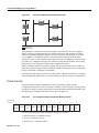
Following is an example of how to configure a router with a fault-tolerant boot sequence.
goriot# configure terminal
Enter configuration commands, one per line. End with CNTL/Z.
goriot(config)# boot system flash gsxx
goriot(config)# boot system gsxx 131.108.1.101
goriot(config)# boot system rom
goriot(config)# ^Z
goriot#
%SYS-5-CONFIG_I: Configured from console by console
goriot# copy running-config startup-config
[ok]
goriot#
Using this strategy, a router has three sources from which to boot: Flash memory, netboot, and ROM.
Providing alternative sources can help to mitigate any failure of the TFTP server or the network.
Note The configuration register must be set to allow ROM image booting after failed netbooting
attempts. For more information, refer to the hardware configuration manual for your platform.
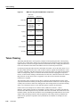
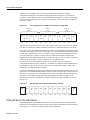
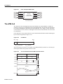
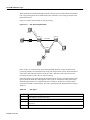
Timeouts and Out-of-Order Packets
When netbooting, a client might need to retransmit requests before receiving a response to an ARP
request. These retransmissions can result in timeouts and out-of-order packets.
Timeouts (shown as periods in a netbooting display) and out-of-order packets (shown as
uppercase Os) do not necessarily prevent a successful netboot. It is acceptable to have either or both
timeouts or out-of-order packets occur during the netboot process.
The following examples show console output from netbooting sessions that were successful even
though timeouts and out-of-order packets occurred (exclamation points represent successfully
received packets):
Booting gs3-bfx from 131.108.1.123: !.!!!!!!!!!!!!!!!!!!!!!!
Booting gs3-bfx from 131.108.1.123: !O.O!!!!!!!!!!!!!!!!!!!!!!
If a netboot generates excessive out-of-order packets and timeouts, problems might result. These
problems are discussed later in this chapter, in the section “Booting: Timeouts and Out-of-Order
Packets Prevent Netbooting.”
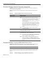
Information for Technical Support
If you cannot resolve your booting problem using the procedures outlined in this chapter, collect the
following information for your technical support representative:
•
ROM images. (Use the show version exec command.)
Troubleshooting Hardware and Booting Problems 3-19
Troubleshooting Hardware
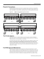
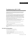
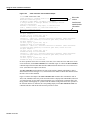
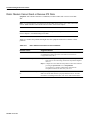
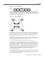
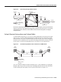
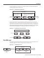
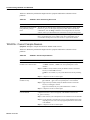
•
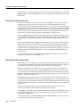
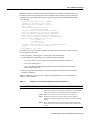
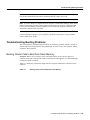
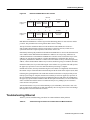
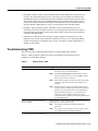
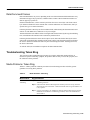
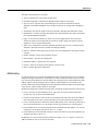
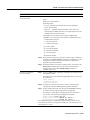
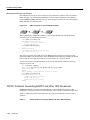
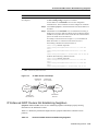
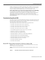
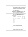
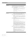
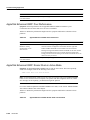
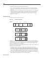
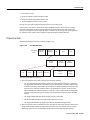
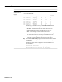
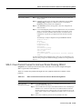
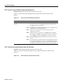
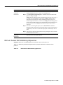
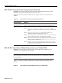
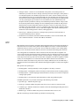
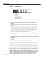
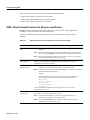
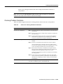
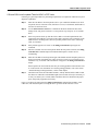
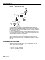
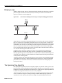
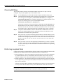
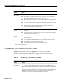
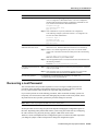
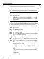
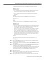
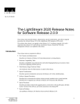
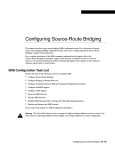
Programmable ROM labels. (This information is printed on the physical chip, and an example is
shown in Figure 3-1.)
Figure 3-1
An Example of a Boot ROM Label—Boot ROM Version 11.1(2)
U30 v11 1(2)
RS P2-ROMMON
O17-2111-04
Cisco Systems
•
•
NVRAM configurations for client and adjacent routers.
Debugging output from adjacent routers using the following privileged exec commands:
— debug ip packet
— debug arp
— debug ip udp
— debug tftp
For more information about these debug commands, refer to the Debug Command Reference.
Troubleshooting Hardware
This section discusses procedures for connectivity problems related to booting. It describes specific
booting symptoms, the problems that are likely to cause each symptom, and the solutions to those
problems.
Cisco 7500 Series Startup
When you start up a Cisco 7500 series router, the following should occur:
3-20
Book Title
•
The AC (or DC) OK LED should go on immediately and should remain on as long as the system
is receiving power.
•
•
The blower should be operating.
•
The Enabled LED on each interface processor should go on (to indicate that the RSP has
completed initialization of the interface processor).
The Route Switch Processor (RSP) and front-panel Normal LEDs should go on (to indicate
normal system operation) and should remain on during system operation; the CPU Halt LED
should remain off.
Cisco 7500 Series Startup
When the 7500 series system has initialized successfully, the system banner should be displayed on
the console screen. If it is not displayed, make sure that the console terminal is properly connected
to the RSP console port and that the terminal is set correctly. The system banner should look similar
to the following:
System Bootstrap, Version 4.6(5), SOFTWARE
Copyright (c) 1986-1995 by cisco Systems
RSP2 processor with 16384 Kbytes of memory
### [...] ###
F3: 2012356+47852+194864 at 0x1000
Restricted Rights Legend
Use, duplication, or disclosure by the Government is
subject to restrictions as set forth in subparagraph
(c) of the Commercial Computer Software - Restricted
Rights clause at FAR sec. 52.227-19 and subparagraph
(c) (1) (ii) of the Rights in Technical Data and Computer
Software clause at DFARS sec. 252.227-7013.
cisco Systems, Inc.
170 Tasman Drive
San Jose, CA 95134
GS Software (RSP-K), Version 10.3(571) [fc3], RELEASE SOFTWARE
Copyright (c) 1986-1995 by cisco Systems, Inc.
[...]
Press RETURN to get started!
If a problem occurs, try to isolate the problem to a specific subsystem. The Cisco 7500 series routers
have the following subsystems:
•
•
Power subsystem—Power supplies, external power cable, and backplane
Cooling subsystem—Depending on your system, includes the following:
— Cisco 7505: Fan tray, fan tray spare with six individual fans, and fan control board
— Cisco 7507: Chassis blower
— Cisco 7513: Blower module, including blower, blower-speed control board, front-panel
LEDs, and the module itself
•
Processor subsystem—Depending on your system, includes all interface processors and either
the RSP1 or the RSP2
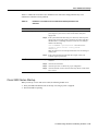
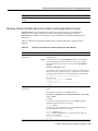
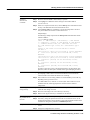
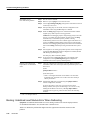
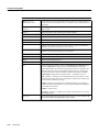
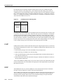
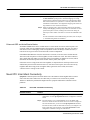
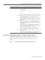
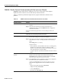
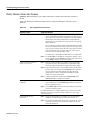
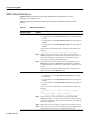
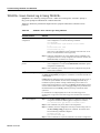
Table 3-1 outlines the areas where Cisco 7500 series startup problems may occur and describes
solutions to those problems.
Table 3-1
Hardware: Cisco 7500 Series Startup Problems and Solutions
Possible Problem Area
Solution
Power subsystem
Step 1
Check to see whether the blower is operating and LEDs on the
processor modules are on. If the blower and LEDs are on but the Power
Supply LED is off, there is probably a faulty Power Supply LED.
Step 2
Make sure the power switch is set correctly to the on position.
Step 3
Make sure the power source, power cable, and power supply are
functioning correctly. Swap parts to see whether one of the components
is faulty.
Step 4
Ensure that the blower module is seated properly. Make sure that the
blower control board edge connector is inserted fully in the backplane
socket.
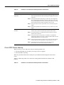
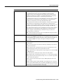
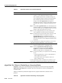
Troubleshooting Hardware and Booting Problems 3-21
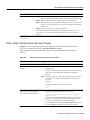
Troubleshooting Hardware
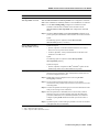
Possible Problem Area
Solution
Cooling subsystem
Step 1
Check to see whether the blower is operating when you start up the
system. If the blower is not operating, there might be a problem with the
blower or the +24 V DC power:
• If the Output Fail LED is on, there might be a problem with the +24V
DC supply to the blower or fan tray at either the power supply or the
blower control board.
• If the blower is not operating and the Output Fail LED is off, ensure
that the blower module is seated properly. Ensure that the blower
control board edge connector is inserted fully in the backplane
socket.
Step 2
If the system and blower start up but shut down after about two minutes,
one or more fans might have failed or might be operating out of
tolerance. You will probably see an error message similar to the
following:
%ENVM-2-FAN: Fan has failed, shutdown in 2 minutes
If the blower or the blower control board fails, you must replace the
blower module.
Step 3
If you see the following message at startup, the system has detected an
overtemperature condition or out-of-tolerance power inside the chassis:
Queued messages:
%ENVM-1-SHUTDOWN: Environmental Monitor initiated
shutdown
If an environmental shutdown results from an out-of-tolerance power
condition, the Output Fail LED goes on before the system shuts down.
This shutdown message might also indicate a faulty component or
temperature sensor. Before the system shuts down, use the show
environment or show environment table commands to display the
internal chassis environment.
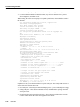
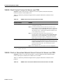
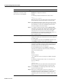
Processor subsystem
1
3-22
Book Title
RSP = Route Switch Processor
Step 4
Ensure that heated exhaust air from other equipment is not entering the
inlet vents, and that there is sufficient clearance around the chassis to
allow cooling air to flow.
Step 1
Check the RSP1 LEDs. If no LEDs come on, ensure that the power
supplies and blower are functioning properly.
Step 2
Check the seating of the RSP. If the RSP is not seated properly, it will
hang the system.
Step 3
If the RSP CPU Halt LED is on, the system has detected a processor
hardware failure. Contact a technical support representative for
instructions.
Step 4
Check to see whether the RSP Normal LED is on, indicating that the
system software has initialized successfully and the system is
operational.
Step 5
Check the Enabled LED on each interface processor. This LED should
go on when the RSP has initialized the interface processor.
Step 6
If the Enabled LED on an individual interface processor is off, the
interface processor might have pulled away from the backplane. If the
interface processors are not seated properly, they will hang the system.
Cisco 7000 Series Startup
Cisco 7000 Series Startup
When you start up a Cisco 7000 series router, the following should occur:
•
The DC OK LED should go on and should remain on as long as the system is receiving source
power.
•
•
The fans should be operating.
•
The Enabled LED on the Switch Processor (SP) or Silicon Switch Processor (SSP) and each
interface processor should go on when the RP has completed initialization of the interface
processor or SP (or SSP) for operation.
The Route Processor (RP) Normal LED should go on and stay on to indicate normal system
operation; the Halt CPU LED should remain off.
When the system has initialized successfully, the system banner should be displayed on the console
screen. If it is not displayed, make sure that the console terminal is properly connected to the RP
console port and that the terminal is set correctly. The system banner should look similar to the
following:
System Bootstrap, Version 4.6(5), SOFTWARE
Copyright (c) 1986-1995 by cisco Systems
RP1 processor with 16384 Kbytes of memory
### [...] ###
F3: 2012356+47852+194864 at 0x1000
Restricted Rights Legend
Use, duplication, or disclosure by the Government is
subject to restrictions as set forth in subparagraph
(c) of the Commercial Computer Software - Restricted
Rights clause at FAR sec. 52.227-19 and subparagraph
(c) (1) (ii) of the Rights in Technical Data and Computer
Software clause at DFARS sec. 252.227-7013.
cisco Systems, Inc.
170 West Tasman Drive
San Jose, California 95134-1706
GS Software (GS7), Version 10.3(1) [fc3], RELEASE SOFTWARE
Copyright (c) 1986-1995 by cisco Systems, Inc.
RP1 (68040) processor with 16384K bytes of memory.
[...]
Press RETURN to get started!
If problems occur, try to isolate the problem to a specific subsystem. The Cisco 7000 series routers
have the following subsystems:
•
Power subsystem—Includes power supplies, fans, external power cable, and internal power
harness that connects to the backplane
•
Cooling subsystem—Depending on your system, the cooling subsystem includes the following:
— Cisco 7000: Chassis blower
— Cisco 7010: Fan tray assembly, including six individual fans, the fan control board, and the
tray itself
•
Processor subsystem—Includes the RP, SP (or SSP), and all interface processors
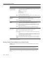
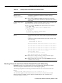
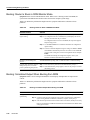
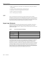
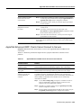
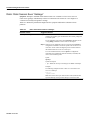
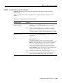
Table 3-2 outlines the areas where Cisco 7000 series startup problems may occur and describes
solutions to those problems.
Troubleshooting Hardware and Booting Problems 3-23
Troubleshooting Hardware
Table 3-2
Hardware: Cisco 7000 Series Startup Problems and Solutions
Possible Problem Area
Solution
Power subsystem
Step 1
Check to see whether the DC OK LED is on.
Step 2
If the LED is not on but the fans are operating and LEDs on the
processor modules are on, the Power Supply LED might be faulty.
Step 3
If the LED is not on and there is no other activity, make sure the power
switch is fully in the on position.
Step 4
Make sure the power source, power cable, and power supply are
functioning correctly. Swap parts to see whether one of the components
is faulty.
Step 5
Ensure that the fan tray is seated properly. Make sure the fan control
board edge connector is inserted fully in the backplane socket.
Step 1
Check to see whether the fans are operating.
Step 2
If the fans are not operating and the DC OK LED is off, there might be a
problem with the +24V DC power.
Step 3
Ensure that the fan tray is seated properly. Make sure that the fan
control board edge connector is inserted fully in the backplane socket.
Step 4
If the system and the fans start up but shut down after about two
minutes, one or more fans has failed or is operating out of tolerance.
You will see an error message similar to the following:
Cooling subsystem
%ENVM-2-FAN: Fan array has failed, shutdown in 2
minutes
If one or more fans or the fan control board fails, you must replace the
fan tray.
Step 5
If you see the following error message, the system has detected an
overtemperature condition or out-of-tolerance power inside the chassis:
Queued messages:
%ENVM-1-SHUTDOWN: Environmental Monitor initiated
shutdown
If an environmental shutdown results from an out-of-tolerance power
condition, the DC OK LED will go off before the system shuts down.
This shutdown message could also indicate a faulty component or
temperature sensor. Use the show environment or show environment
table command to display the internal chassis environment.
Step 6
3-24
Book Title
Make sure that heated exhaust air from other equipment is not entering
the inlet vents, and that there is sufficient clearance around the chassis
to allow cooling air to flow.
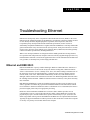
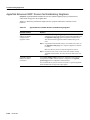
Cisco 4000 and Cisco 3000 Series Startup
Possible Problem Area
Solution
Processor subsystem
Step 1
Check to see whether the RP1 LEDs come on when system power is
turned on.
Step 2
If none of the RP LEDs come on, make sure that both the fan and power
supply are functioning properly.
Step 3
If the power supply and fans appear operational but none of the RP
LEDs are on, an improperly connected RP, SP2 (or SSP3), or interface
processor might have hung the bus.
Step 4
If the SP (or SSP) Enabled LED is off but any of the RP LEDs are on,
make sure the SP (or SSP) is seated in its slot properly.
Step 5
Check to see whether the Boot Error LED is on. If the LED is on, the
system software is unable to start up. If you have a spare RP with the
system software ROMs installed, replace the installed RP with the spare
to see whether the system will boot.
Step 6
Check to see whether the RP CPU Halt LED is on. If it is, the system
has detected a processor hardware failure. Contact a technical support
representative for more information.
Step 7
Check to see whether all interface processor Enabled LEDs are on.
Step 8
If the Enabled LED on an individual interface processor is off, make
sure that the interface processor has not pulled away from the
backplane.
1
2
3
RP = Route Processor
SP = Switch Processor
SSP = Silicon Switch Processor
Cisco 4000 and Cisco 3000 Series Startup
When you start up a Cisco 4000 or a Cisco 3000 series router, the following should occur:
•
•
The System OK LED should come on and stay on as long as power is supplied.
The fans should be operating.
Troubleshooting Hardware and Booting Problems 3-25
Troubleshooting Hardware
When the system has initialized successfully, the system banner should be displayed on the console
screen. The system banner should look similar to the following:
System Bootstrap, Version 4.14(9), SOFTWARE
Copyright (c) 1986-1994 by cisco Systems
4000 processor with 16384 Kbytes of main memory
Loading xx-j-mz.112-0.15 at 0x4A790, size = 3496424 bytes [OK]
F3: 8988+3487404+165008 at 0x12000
Self decompressing the image : ###[...]#### [OK]
Restricted Rights Legend
Use, duplication, or disclosure by the Government is
subject to restrictions as set forth in subparagraph
(c) of the Commercial Computer Software - Restricted
Rights clause at FAR sec. 52.227-19 and subparagraph
(c) (1) (ii) of the Rights in Technical Data and Computer
Software clause at DFARS sec. 252.227-7013.
cisco Systems, Inc.
170 West Tasman Drive
San Jose, California 95134-1706
Cisco Internetwork Operating System Software
IOS (tm) 4000 Software (XX-J-M), Version 11.2(0.15), BETA TEST SOFTWARE
Copyright (c) 1986-1996 by cisco Systems, Inc.
Compiled Wed 03-Jul-96 01:21 by susingh
Image text-base: 0x00012000, data-base: 0x006F6494
cisco 4000 (68030) processor (revision 0xA0) with 16384K/4096K bytes of memory.
Processor board ID 5007155
G.703/E1 software, Version 1.0.
Bridging software.
SuperLAT software copyright 1990 by Meridian Technology Corp).
X.25 software, Version 2.0, NET2, BFE and GOSIP compliant.
TN3270 Emulation software (copyright 1994 by TGV Inc).
Basic Rate ISDN software, Version 1.0.
2 Ethernet/IEEE 802.3 interfaces.
4 Serial network interfaces.
8 ISDN Basic Rate interfaces.
128K bytes of non-volatile configuration memory.
4096K bytes of processor board System flash (Read/Write)
Press RETURN to get started!
If problems occur, try to isolate the problem to a specific subsystem. The Cisco 4000 and Cisco 3000
series routers have the following subsystems:
3-26
Book Title
•
•
Power subsystem—This subsystem includes the power supply and the wiring.
•
Network processor modules (NPMs)—This subsystem includes all NPMs installed in the router
chassis.
•
System cables—This subsystem includes all the external cables that connect the router to the
network.
Cooling subsystem—This subsystem includes the blower assembly, which should come on when
power is applied.
Cisco 2500 Series Startup
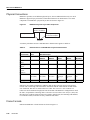
Table 3-3 outlines the areas where Cisco 4000 and Cisco 3000 series startup problems may occur
and describes solutions to those problems.
Table 3-3
Hardware: Cisco 4000 and Cisco 3000 Series Startup Problems and
Solutions
Possible Problem Area
Solution
Power and cooling subsystems
Step 1
Check to see whether the blower is operating. If it is not, check the AC
power input, AC power source, router circuit breaker, and power
supply cable.
Step 2
If the system shuts down after being on a short time, check the power
supply. If the power supply appears operational, the router might have
shut down due to overheating. Check the console for error messages
similar to the following:
%SYS-1-OVERTEMP: System detected OVERTEMPERATURE
condition. Please resolve cooling problem
immediately!
Make sure that the fans are working and that there is no air blockage to
cooling vents.
NPMs1 and cables
1
Step 3
If the system partially boots but LEDs do not light, contact your
technical support representative.
Step 1
Make sure that NPMs are properly connected to the motherboard
connector.
Step 2
Check the external cables.
Step 3
Check the processor or software for proper configuration.
Step 4
Check the external console connection and verify that the console baud
rate is correct.
NPM = network processor module
Cisco 2500 Series Startup
When you start up a Cisco 2500 series router, the following should occur:
•
•
The System OK LED should come on and stay on as long as power is supplied.
The fans should be operating.
Troubleshooting Hardware and Booting Problems 3-27
Troubleshooting Hardware
When the system has initialized successfully, the system banner should be displayed on the console
screen. The system banner should look similar to the following:
System Bootstrap, Version (3.3), SOFTWARE
Copyright (c) 1986-1993 by cisco Systems
2500 processor with 16384 Kbytes of main memory
Unknown or ambiguous service arg - udp-small-servers
Unknown or ambiguous service arg - tcp-small-servers
Booting igs-in-l.110-9 from Flash address space
F3: 3844616+90320+228904 at 0x3000060
Restricted Rights Legend
Use, duplication, or disclosure by the Government is
subject to restrictions as set forth in subparagraph
(c) of the Commercial Computer Software - Restricted
Rights clause at FAR sec. 52.227-19 and subparagraph
(c) (1) (ii) of the Rights in Technical Data and Computer
Software clause at DFARS sec. 252.227-7013.
cisco Systems, Inc.
170 West Tasman Drive
San Jose, California 95134-1706
Cisco Internetwork Operating System Software
IOS (tm) 3000 Software (IGS-IN-L), Version 11.0(9), RELEASE SOFTWARE (fc1)
Copyright (c) 1986-1996 by cisco Systems, Inc.
Compiled Tue 11-Jun-96 01:15 by loreilly
Image text-base: 0x03020F8C, data-base: 0x00001000
cisco 2500 (68030) processor (revision A) with 16384K/2048K bytes of memory.
Processor board ID 01062462, with hardware revision 00000000
Bridging software.
X.25 software, Version 2.0, NET2, BFE and GOSIP compliant.
Basic Rate ISDN software, Version 1.0.
1 Ethernet/IEEE 802.3 interface.
2 Serial network interfaces.
1 ISDN Basic Rate interface.
32K bytes of non-volatile configuration memory.
4096K bytes of processor board System flash (Read ONLY)
Press RETURN to get started!
If problems occur, try to isolate the problem to a specific subsystem. The Cisco 2500 series routers
have the following subsystems:
•
•
Power subsystem—This subsystem includes the power supply and the wiring.
•
Network interfaces—This subsystem includes all network interfaces, such as Ethernet, Token
Ring, serial, or ISDN Basic Rate Interface (BRI).
•
System cables—This subsystem includes all the external cables that connect the router to the
network.
Cooling subsystem—This subsystem includes the fan, which should go on when power is
applied.
Table 3-4 outlines the areas where Cisco 2500 series startup problems may occur and describes
solutions to those problems.
3-28
Book Title
Cisco 2000 Series Startup
Table 3-4
Hardware: Cisco 2500 Series Startup Problems and Solutions
Possible Problem Area
Solution
Power and cooling
subsystems
Step 1
If the Power LED is off, make sure the power supply is plugged in to the
wall receptacle and that the cable from the power supply to the router is
connected.
Step 2
If the system shuts down after being on a short time, there might have
been a thermal-induced shutdown caused by a faulty fan, or the power
to the system might have been lost. Ensure that the system is receiving
power and that the chassis intake and exhaust vents are clear.
Step 3
If the system does not boot up but LEDs are on, check the 12V power
supply.
Step 4
If the system partially boots but LEDs are not on, check the 5V power
supply.
Step 1
If a network interface is not recognized by the system, check the
interface cable connection and the LED on the network interface.
Step 2
If a network interface is recognized but will not initialize, check the
interface cable connection.
Step 3
If the system will not boot properly or constantly or intermittently
reboots, there might be a processor or software problem. Make sure that
DRAM SIMM modules are seated properly.
Step 4
If the system boots but the console screen is frozen, check the external
console connection and verify that the console baud rate is correct.
Step 5
If the system powers on and boots with a particular interface
disconnected, check the network interface connection.
Network interfaces
and cables
Cisco 2000 Series Startup
When you start up a Cisco 2000 series router, the following should occur:
•
•
The OK LED should come on and stay on as long as power is supplied.
The fans should be operating.
When the system has initialized successfully, the system banner should be displayed on the console
screen.
Table 3-5 outlines the possible Cisco 2000 series startup problem and describes solutions to that
problem.
Table 3-5
Hardware: Cisco 2000 Series Startup Problem and Solutions
Troubleshooting Hardware and Booting Problems 3-29
Troubleshooting Hardware
Possible Problem
Solution
Bootup problem
Step 1
Check to see whether the fan is operating. If it is not, check the fan or the 12V
power supply.
Step 2
If the system shuts down after being on for a short time, check the power
supply.
Step 3
If the power supply appears operational, the router might have shut down due to
overheating. Ensure that the chassis intake and exhaust vents are clear.
Step 4
If the system does not boot up but the System OK LED is on, check the 12V
power supply to make sure it is not faulty.
Step 5
If the system partially boots but the System OK LED is not on, check the 5V
power supply to make sure it is not faulty.
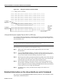
Catalyst 5000 Series Startup
When you start up a Catalyst 5000 series LAN switch, the following should occur:
•
•
The PS1 and PS2 LEDs on the supervisor engine module faceplate should be green.
•
The Status LED on the supervisor engine module and all interfaces should be orange until the
boot is complete.
The system fan assembly should be operating and the Fan LED on the supervisor engine module
should come on.
When the system boot is complete, the supervisor engine module should initialize the switching
modules. The status LED on each switching module goes on when initialization has been completed,
and the console screen displays a script and system banner similar to the following:
ATE0
ATS0=1
Catalyst 5000 Power Up Diagnostics
Init NVRAM Log
LED Test
ROM CHKSUM
DUAL PORT RAM r/w
RAM r/w
RAM address test
Byte/Word Enable test
RAM r/w 55aa
RAM r/w aa55
EARL test
BOOTROM Version 1.4, Dated Dec 5 1995 16:49:40
BOOT date: 00/00/00 BOOT time: 03:18:57
SIMM RAM address test
SIMM Ram r/w 55aa
SIMM Ram r/w aa55
Start to Uncompress Image ...
IP address for Catalyst not configured
BOOTP will commence after the ports are online
Ports are coming online ...
Cisco Systems Console
If problems occur, try to isolate the problem to a specific subsystem. The Catalyst 5000 series LAN
switches have the following subsystems:
•
•
3-30
Book Title
Power subsystem—This subsystem includes the power supplies and power supply fans.
Cooling subsystem—This subsystem includes the chassis fan assembly, which should be
operating when the system power is on.
Catalyst 3000 Series Startup
•
Processor and interface subsystem—This subsystem includes the supervisor engine module
(which contains the system operating software), the network interfaces, and all associated
cabling.
Table 3-6 outlines the areas where Catalyst 5000 series startup problems may occur and describes
solutions to those problems.
Table 3-6
Hardware: Catalyst 5000 Series Startup Problems and Solutions
Possible Problem Area
Solution
Power subsystem
Step 1
Check to see whether the PS1 LED is on. If it is not, ensure that the
power supply is connected properly and is flush with the back of the
chassis. Make sure that captive installation screws are tight.
Step 2
Check the AC source and the power cable. Connect the power cord to
another power source if one is available and turn the power back on. If
the LED fails to go on after you connect the power supply to a new
power source, replace the power cord.
Step 3
If the LED fails to go on when the switch is connected to a different
power source with a new power cord, the power supply is probably
faulty. If a second power supply is available, install it in the second
power supply bay and contact a customer service representative for
further instructions.
Step 4
Repeat these steps for the second power supply if present.
Step 1
Check to see whether the Fan LED on the supervisor engine module is
green. If it is not, check the power subsystem to see whether it is
operational.
Step 2
If the Fan LED is red, the fan assembly might not be seated properly
in the backplane.
Cooling subsystem
To ensure that the fan assembly is seated properly, loosen the captive
installation screws, remove the fan assembly, and reinstall it. Tighten
all captive installation screws and restart the system.
Processor and interface
subsystem
Step 3
If the Fan LED is still red, the system has probably detected a fan
assembly failure. Contact a technical support representative for
assistance.
Step 1
Check the supervisor engine module Status and Link LEDs. These
should both be green if all diagnostic and self-tests were successful
and ports are operational. For more information about interpreting the
supervisor engine module LEDs, refer to the user guide for your
switch.
Step 2
Check the LEDs on individual interface modules. In most cases these
should be green (or should flicker green, in the case of Transmit and
Receive LEDs) if the interface is functioning correctly. For detailed
information on interpreting interface module LEDs, refer to the user
guide for your switch.
Step 3
Check all cabling and connections. Replace any faulty cabling.
Catalyst 3000 Series Startup
When you start up a Catalyst 3000 series LAN switch, the following should occur:
•
The Power LED should come on.
Troubleshooting Hardware and Booting Problems 3-31
Troubleshooting Hardware
•
•
The fan should begin operating and should stay on while power is applied to the system.
On some models, the DIAG LED should come on, stay on for the duration of the system’s
self-test diagnostics, and then turn off.
While booting, the console screen displays a script and system banner, which should be similar to
the following:
Cisco Catalyst Boot Firmware P/N 57-1327-02, Copyright 1995
- Initiating bootstrapping sequence.
- Boot image integrity check...Passed.
- Control transferred to boot process.
- Relocating main image to DRAM.......Done.
- Main image integrity check...succeeded.
- Control transferred to main process.
Cisco Catalyst 3000 System Software Version 1.1.1-B7, Copyright 1994,
1995.
System started on Fri. November 17, 1995 13:02:46
4 Megabytes System memory
2 Megabytes Network memory
- Initialization started
- File system initialized
- System temperature is within safe operating levels
- Warmboot initialization started
- Checking file system integrity
- LAN ports detected:
- 10Base-T : 1 2 3 4 5 6 7 8 9 10 11 12 13 14 15 16
- StkPort
: 25
- Initializing Ports: 1 2 3 4 5 6 7 8 9 10 11 12 13 14 15 16 25
- Initializing system address table
- No existing diagnostic information, forcing diagnostic mode
- Starting Power Up Diagnostics test
- UART loopback test on diagnostic port...Passed
- UART loopback test on console port...Passed
- RTC memory test...Passed
- Real Time Clock test...Passed
- CPU loopback test..............Passed
- Ethernet Port loopback test...................Passed
- Ethernet Port fast transmit loopback test...................Passed
- Ethernet Port fast receive loopback test...................Passed
- Ethernet Port cross port loopback test...................Passed
- Ethernet Port broadcast test...................Passed
- Catalyst Stack Port loopback test...Passed
- Catalyst Stack Port cross port loopback test...Passed
- Catalyst Stack Port broadcast test...Passed
- CPU broadcast test...Passed
- Completed Power Up Diagnostics test
- System entering stand-alone mode
- Catalyst initiating bootp requests on one or more VLANs
- System initialization complete
- Enabling port: 1 2 3 4 5 6 7 8 9 10 11 12 13 14 15 16 25
Press RETURN key to activate console...
If problems occur, try to isolate the problem to a specific subsystem. The Catalyst 3000 series LAN
switches have the following subsystems:
3-32
Book Title
•
•
Power subsystem—This subsystem includes the input power, AC power cable, and power supply.
•
Network interfaces and system cables subsystem—This subsystem includes all the network
interfaces and the cables that connect the equipment to the network.
Cooling subsystem—This subsystem includes the fans, which should be operating when the
system power is on.
Catalyst 2900 Series Startup
Table 3-7 outlines the areas where Catalyst 3000 series startup problems may occur and describes
solutions to those problems.
Table 3-7
Hardware: Catalyst 3000 Series Startup Problems and Solutions
Possible Problem Area
Solution
Power and cooling
subsystems
Step 1
Check to see whether the Power LED is on. If it is not on
and the fans are not running, check the AC power cord and
the AC receptacle the cord is plugged in to.
Make sure the cord is intact and properly attached. Swap the
cord with another cord to see whether the cord is faulty.
Make sure the receptacle is receiving power.
Network interfaces and system
cables subsystem
1
Step 2
If the Fault LED comes on after power up or after the unit
has been running for a period of time, cycle the power to the
unit.
Step 3
Check to see whether the fans are running and that the
chassis intake vents and exhaust ports are clear.
Step 4
View the console to check whether a temperature error has
been reported. If you continue to experience power
problems, or if temperature errors are being reported to the
console and you cannot isolate a specific cause and correct
it, contact the Cisco TAC.1
Step 1
If a network interface is not recognized by the system,
check the interface cable and connection and the LED that
corresponds to the network interface.
Step 2
If a network interface is recognized but will not
communicate properly, check the interface cable and
connections.
Step 3
If the system will not boot properly or intermittently
reboots, the processor may be faulty or the hardware or
software setup may be incorrect.
Step 4
If the system boots but the console is frozen, check the
external console connection and verify the console setup.
TAC = Technical Assistance Center
Catalyst 2900 Series Startup
When you start up a Catalyst 2900 series LAN switch, the following should occur:
•
The PS LED on the supervisor engine module faceplate should come on and stay green while
power is applied to the system.
•
The system fan assembly and Fan LED should come on and stay on while power is applied to the
system.
•
The Status LED on the supervisor engine module and on each interface should be orange until
the boot is complete.
Troubleshooting Hardware and Booting Problems 3-33
Troubleshooting Hardware
When the system boot is complete, the supervisor engine module initializes the switching modules.
The status LED on each switching module goes on when initialization has been completed, and the
console screen displays a script and system banner similar to the following:
BOOTROM Version 2.1, Dated May 22 1996 15:17:09
Boot date: 05/22/96 BOOT time: 15:17:09
Executing from RAM
Cisco Systems Console
Sending RARP request with address 00:40:0b:a0:05:b8
Sending bootp request with address 00:40:0b:a0:05:b8
Sending RARP request with address 00:40:0b:a0:05:b8
Sending bootp request with address 00:40:0b:a0:05:b8
No bootp or rarp response received
Enter password:
If problems occur, try to isolate the problem to a specific subsystem. The Catalyst 2900 series LAN
switches have the following subsystems:
•
•
Power subsystem—This subsystem includes the power supplies and power supply fans.
•
Processor and interface subsystem—This subsystem includes the supervisor engine module
(which contains the system operating software), the network interfaces, and all associated
cabling.
Cooling subsystem—This subsystem includes the chassis fan assembly, which should be
operating when the system power is on.
Table 3-8 outlines the areas where Catalyst 2900 series startup problems may occur and describes
solutions to those problems.
Table 3-8
Hardware: Catalyst 2900 Series Startup Problems and Solutions
Possible Problem Area
Solution
Power subsystem
Step 1
Check the Power LED. If it is off, ensure that the power
supply cord is not damaged and that it is properly attached
to the power supply and to an AC receptacle.
Step 2
If the LED is red, the power supply has detected an anomaly
or voltage outage and needs to be serviced. Contact your
technical support representative for instructions.
Step 1
Check to see whether the Fan LED on the supervisor engine
module is green. If it is not, check the power subsystem to
see whether it is operational.
Step 2
If the Fan LED is red, contact a technical support
representative for assistance.
Cooling subsystem
3-34
Book Title
Catalyst 1600 Token Ring Switch Startup
Possible Problem Area
Solution
Series processor and interface subsystem
Step 1
Check the supervisor engine module Status and Link LEDs.
These should both be green if all diagnostic and self-tests
were successful and ports are operational. For more
information about interpreting the supervisor engine
module LEDs, refer to the user guide for your switch.
Step 2
Check the LEDs on individual interface modules. In most
cases these should be green (or should flicker green, in the
case of transmit and receive LEDs) if the interface is
functioning correctly. For detailed information on
interpreting interface module LEDs, refer to the user guide
for your switch.
Step 3
Check all cabling and connections. Replace any faulty
cabling.
Catalyst 1600 Token Ring Switch Startup
When you start up a Catalyst 1600 Token Ring switch, the self-test program automatically checks to
see whether the switch is operating correctly. The self-test begins by testing low-level hardware
functions and then conducts high-level self-tests. During the high-level self-test, the LCD panel
displays the following:
•
•
The version number of the boot software, and the date and time that the software was released
•
A “System Self Test PASSED” message indicating that the self-test is complete and the Catalyst
1600 has passed the test
The number of each stage in the self-test (these are usually displayed too quickly for the numbers
to be visible)
Table 3-9 outlines possible Catalyst 1600 Token Ring switch startup problems and describes
symptoms to those problems.
Table 3-9
Hardware: Catalyst 1600 Token Ring Switch Startup Problems and
Symptoms
Possible Problem
Symptom
Low-level test failure
The startup process is halted.
High-level test failure
The self-test program restarts and the number of the failed test is
displayed. High-level tests are repeated until the self-test is
completed successfully.
Hardware error
Contact your technical support representative. Be sure to note the
number of the failed test and the version number of the software
containing the self-test program.
LightStream 2020 Startup
When you start up a LightStream 2020 ATM switch, the blowers start running and the test and
control system (TCS) applies power to the cards and initiates a series of diagnostics known as the
power-on self-test (POST). POST diagnostics run automatically on each card whenever the system
or the slot is powered up or when the card is reset. If a card passes POST, the green RDY LED turns
on. If a card fails POST, its yellow FLT LED turns on.
Troubleshooting Hardware and Booting Problems 3-35
Troubleshooting Hardware
Table 3-10 outlines the possible LightStream 2020 problems and describes solutions to those
problems.
Table 3-10
Hardware: LightStream 2020 Startup Problems and Solutions
Possible Problem
Solution
System initialization
problem
Step 1
Make sure power cords and data cables are firmly connected at both
ends.
Step 2
Make sure all cards (front and back of the chassis) are firmly seated
in the midplane and screwed securely to the chassis.
Step 3
Make sure power supplies, blowers, and disk drives are properly
connected and screwed securely to the chassis.
Blower problem
If you are experiencing any of the following symptoms, you might need to
replace the blower:
• The temperature on one or more cards is out of the recommended range.
• The system is powered on, but the blower is not turning, is making noise,
or is exhausting air.
• Two minutes after the system is powered on, the blower fails to reduce its
speed in a room temperature environment.
• The system is powered on, but the blower’s green LED is off. The LED
indicates that the blower is turning at a rate of at least 1500 rotations per
minute.
Bulk power tray problems
In a system with one power tray, no power will be present if the power tray is
faulty. There might be a problem with the power tray if cycling the system’s
power has no effect.
A system with two power trays can operate normally when only one is
working. If you suspect a problem, use the CLI1 command show chassis
powersupply. If a status line for an occupied slot says anything other than
Good, check the faulty power tray to see that it is properly connected.
Replace the power tray if necessary.
Switch card problems
If you are experiencing any of the following symptoms, you might need to
replace the switch card:
• POST2 fails (the FLT3 LED stays lit and POST results indicate a
problem).
• The Switch card fails even when moved to the other slot. (If the card fails
in one slot but operates properly in another, suspect a problem with the
midplane.)
• Diagnostics that loop data through the switch card fail on two or more
function cards.
• The Switch card fails to come up or to select a TCS4 hub.
• Traffic is not passing through the system, but the line cards and NPs5 are
operational.
• The system has data transmission problems that do not go away when you
replace the card that appears to be failing or that occur in several cards
simultaneously. (Problems of this type may also indicate a faulty
midplane.)
• The switch card cannot be fully inserted into its slot. This probably
indicates damage to the connectors on either the card or the midplane.
Inspect all the connectors and replace the card or the midplane if you find
damage.
3-36
Book Title
LightStream 2020 Startup
Possible Problem
Solution
Network processor
problems
If the NP fails to power up, check its access card at the back of the chassis.
An NP requires an NPAC6; it cannot operate with any other kind of access
card.
If the system fails to boot, it could indicate either a problem with the NP, a
problem with the NP’s hard disk drive, or a problem with the software on the
hard drive.
If you are experiencing any of the following symptoms, you might need to
replace the NP card:
• POST fails (the FLT LED stays lit and the POST results indicate a
problem).
• The NP fails even when moved to the other slot. (If the card fails in one
slot but operates properly in the other, suspect a problem with the
midplane.)
• Hardware diagnostics fail.
• You cannot get to the CLI to run the diagnostics.
• The card fails to load.
• The NP or its access card cannot be fully inserted into its slot. This
probably indicates damage to the connectors on either the card or the
midplane. Inspect all the connectors and replace the card or the midplane
if you find damage.
Troubleshooting Hardware and Booting Problems 3-37
Troubleshooting Hardware
Possible Problem
Solution
Interface module
problems
The following tips will help you distinguish between problems in a line card
and problems in an access card:
• Run the manufacturing diagnostics and check the information provided
for the access card.
• Swap another line card of the same type. If the second card has the same
problem as the first one, the access card is probably at fault. If the second
card works properly, the first line card is likely to be the source of the
problem.
• Faults in the line card are more common than faults in the access card. If
you cannot determine which card is causing a problem, try replacing the
line card.
• Use the looping tests described in the LightStream 2020 Network
Operations Guide.
If you are having trouble bringing up an interface module, check the
following:
• Make sure the access card behind the line card is compatible with the line
card.
The low-speed line card (LSC) is compatible with the following access
card:
— Low-speed access card (LSAC)
The medium-speed line card (MSC) is compatible with the following
access cards:
— T3 medium speed access card (T3 MSAC)
— E3 G.804 medium speed access card (E3 G.804 MSAC)
— E3 PLCP medium speed access card (E3 PLCP MSAC)
The cell line card (CLC) is compatible with the following access cards:
— OC-3c single mode access card (OC3AC SM)—1 or 2 ports
— OC-3c multimode access card (OC3AC MM)—1 or 2 ports
— T3 access card (T3AC)—4 or 8 ports
— E3 access card (E3AC)—4 or 8 ports
3-38
Book Title
LightStream 2020 Startup
Possible Problem
Solution
Interface module
problems
The packet line card is compatible with the following access cards:
— FDDI access card
— Ethernet access card
— Fiber Ethernet access card
— T1 circuit emulation access card
— E1 circuit emulation access card
The NP is compatible with the following access card:
— NPAC
• If an FDDI7 module does not pass traffic, make sure the FDDI cables for
each port are attached to the proper connectors.
• If you are bringing up a low-speed module, make sure the interface
jumpers on the access card are set to match the physical interfaces marked
on the fantails (V.35, X.21 or RS-449).
• If you are bringing up an E1 circuit emulation module, make sure the
interface jumpers on the access card are set properly.
If you are having signal quality problems with a physical interface on an
access card, check the following:
• Make sure that cables are within the specifications of your media type.
• Make sure that connectors are not damaged. Check optical connectors for
dirt or scratches on the optical surface. For electrical connectors, check
that pins are not bent, broken, or loose.
Interface module
problems
If you are experiencing any of the following symptoms, you might need to
replace the line card or its access card:
• POST fails (the FLT LED stays lit and the POST indicates a problem).
• A card fails even when moved to another slot. (When you move a line
card, be sure to pair it with an appropriate access card. When you move an
access card, pair it with an appropriate line card.)
• Hardware diagnostics fail.
• The line card fails to load.
• The line card hangs repeatedly.
• The line card or access card cannot be fully inserted into its slot. This
probably indicates damage to the connectors on either the card or the
midplane. Inspect all the connectors and replace the card or the midplane
if you find damage.
• Two or more ports are passing no traffic, dropping many cells, or flapping.
If only one port has symptoms, there is probably a problem with the line,
the external DSU/CSU if one is present, the access card, or the remote
device. Use the looping tests described in the LightStream 2020 Network
Operations Guide to help isolate the problem.
Troubleshooting Hardware and Booting Problems 3-39
Troubleshooting Hardware
Possible Problem
Solution
Disk assembly problems
Disk assembly problems are indicated by the following symptoms:
• The node fails to boot.
• Files become corrupted.
• In a system with two NPs, the primary NP appears to fail and the backup
takes over. The failed NP might pass diagnostics.
• The system fails to read or write floppy disks. In the case of a write
failure, check the write protect switch on the disk.
If a disk problem is indicated, check the disk assembly connector for bent or
broken pins. If any pins are bent or damaged, they are the likely source of
the problem. Replace the disk assembly connector.
If the connector is in good condition, the problem may be in the disk
assembly itself, or in the software on the disk. If you suspect a problem with
the software, you should be able to correct it by reinstalling the software as
described in the LightStream 2020 Network Operations Guide.
Midplane problems
Midplane problems are indicated by the following symptoms:
• A card fails in one slot but operates normally in other slots.
• Data transmission problems do not go away when you replace the FRU8
that appears to be failing, or problems occur in several FRUs
simultaneously. (Problems of this type might also indicate a faulty switch
card.)
• Failure of a card to fully insert into its slot. This probably indicates
damage to the connectors on either the card or the midplane. Inspect all
the connectors and replace the card or the midplane if you find damage.
• Electrical failure or electrical problems that do not go away when you
replace the FRU that appears to be failing, or that occur in several FRUs
simultaneously. Electrical problems include out-of-range voltages.
1
2
3
4
5
6
7
8
CLI = command-line interface
POST = power-on self-test
FLT = fault
TCS = test and control system
NP = network processor
NPAC = network processor access card
FDDI = Fiber Distributed Data Interface
FRU = field-replaceable unit
Testing and Verifying Replacement Parts
If you are replacing a part or card to remedy a suspected problem, make only one change at a time.
To test a system, start with a simple hardware configuration and add one card at a time until a failed
interface appears or is isolated. Use a simple software configuration and test connectivity using a
ping test.
If you determine that a part or card replacement is required, contact your sales or technical support
representative. Specific instructions concerning part or card installation are outlined in the
configuration note provided with the replacement.
For modular routers, make sure that you seat all cards correctly. Check the seating of cards if the
system is not booting properly. Use the ejector levers to reseat all processor modules, and then
reboot.
3-40
Book Title
Troubleshooting Booting Problems
Note Before accessing the chassis interior and removing any cards, turn off power to the chassis.
Use extreme caution around the chassis. Potentially harmful voltages are present.
Note To prevent damage to components that are sensitive to electrostatic discharge (ESD), attach
ESD protection before opening a chassis. Make certain that the power cord is connected but that
power is off. ESD damage prevention guidelines are provided in the hardware installation and
maintenance publication for your router.
If a part replacement appears to solve a problem, reinstall the suspect part to verify the failure.
Always double-check a repair.
Troubleshooting Booting Problems
This section discusses troubleshooting procedures for connectivity problems related to booting. It
describes specific booting symptoms, the problems that are likely to cause each symptom, and the
solutions to those problems.
Booting: Router Fails to Boot from Flash Memory
Symptom: When a user is booting a router from Flash memory, the boot process appears to
complete, but the router does not route traffic or communicate with neighbors. exec commands might
or might not appear to function.
Table 3-11 outlines the problems that might cause this symptom and describes solutions to those
problems.
Table 3-11
Booting: Router Fails to Boot from Flash Memory
Troubleshooting Hardware and Booting Problems 3-41
Troubleshooting Booting Problems
Possible Problem
Solution
Incorrect or corrupted image
(exec does not function)
Step 1
Check the configuration register using the show version exec
command. Set the register to boot from Flash memory. For
information about configuration register settings, refer to your
hardware installation and maintenance documentation.
Step 2
Power cycle the router.
Step 3
Within the first 60 seconds of booting, press the Break key to
access the ROM monitor.
Step 4
At the ROM monitor prompt (>), enter o/r 0x1 to set the
configuration register to boot from ROM.
Step 5
Enter i to reinitialize the router, which causes the router to
enter setup mode.
Step 6
Obtain the correct system image. If necessary, contact your
technical support representative to determine which image is
correct.
Step 7
After the correct image is identified, use the copy tftp flash
privileged exec command at the router to retrieve the image.
Step 8
Check the configuration register using the show version exec
command. Set the register to boot from Flash memory.
Step 9
Use the show running-config privileged exec command to see
whether the router configuration contains the
boot system flash global configuration command.
Note: Issuing the copy running-config startup-config
command at this point on a Cisco 2500, Cisco 3000,
Cisco 4000, or Cisco 7000 series will overwrite the
configuration. Make sure you have a backup of your
configuration file.
Incorrect or corrupted image
(exec does not function)
Step 10 Include the boot system flash command if it is not in the
configuration. Be sure to use the copy running-config
startup-config command after this change.
Step 11 Enter the reload privileged exec command to restart the router.
Syntax:
The following is the syntax for the reload command:
reload [text] | [in [hh:]mm [text]] | [at hh:mm [month day |
day month] [text]] | [cancel]
Examples:
The following example illustrates how to use the reload
command to immediately reload the software on the router:
Router# reload
The following example illustrates how to use the reload
command to reload the software on the router in 10 minutes:
Router# reload in 10
Router# Reload scheduled for 11:57:08 PDT Fri
Apr 21 1996 (in 10 minutes)
Proceed with reload? [confirm]
Router#
3-42
Book Title
Booting: Vector Error Occurs When Booting from Flash Memory
Possible Problem
Solution
Incorrect or corrupted image
(exec functions)
Step 1
Obtain the correct system image. If necessary, contact your
technical support representative to determine which image is
appropriate.
Step 2
Use the copy tftp flash privileged exec command to retrieve
the image.
Step 3
Check the configuration register using the show version exec
command. Set the register to boot from Flash memory. For
information about configuration register settings, refer to your
hardware installation and maintenance documentation.
Step 4
Use the show running-config privileged exec command to
determine whether the active configuration contains the
boot system flash global configuration command. Use the
show startup-config privileged exec command to determine
whether the boot system flash command is included in the
configuration stored in NVRAM.1
Step 5
Include the boot system flash command if it is not in the
configuration. Be sure to use the copy running-config
startup-config privileged exec command to save your
modification after this change.
Step 6
Enter the reload privileged exec command to restart the router.
Syntax:
The following is the syntax for the reload command:
reload [text] | [in [hh:]mm [text]] | [at hh:mm [month day |
day month] [text]] | [cancel]
Examples:
The following example illustrates how to use the reload
command to immediately reload the software on the router:
Router# reload
Incorrect or corrupted image
(exec functions)
The following example illustrates how to use the reload
command to reload the software on the router in 10 minutes:
Router# reload in 10
Router# Reload scheduled for 11:57:08 PDT Fri
Apr 21 1996 (in 10 minutes)
Proceed with reload? [confirm]
Router#
1
NVRAM = nonvolatile random-access memory
Booting: Vector Error Occurs When Booting from Flash Memory
Symptom: Vector errors occur when a user is booting a router from Flash memory.
Table 3-11 outlines the problems that might cause this symptom and describes solutions to those
problems.
Troubleshooting Hardware and Booting Problems 3-43
Troubleshooting Booting Problems
Figure 3-2
Booting: Vector Error Occurs When Booting from Flash Memory
Possible Problem
Solution
Compressed system
image
Step 1
Power-cycle the router.
Step 2
Within the first 60 seconds of booting, press the Break key to access the ROM
monitor.
Step 3
At the ROM monitor prompt (>), enter o/r to set the configuration register to boot
from ROM.
Step 4
Enter b to boot the router. The router enters setup mode.
Step 5
Press Ctrl-C to bypass the setup.
Step 6
Enter the configure memory privileged exec command.
Step 7
Obtain an uncompressed system image. From the router prompt, use the
privileged exec command copy flash tftp to send the compressed image back to
the TFTP1 server.
Decompress the image at the TFTP server. This cannot be done at the router.
Step 8
Use the copy tftp flash privileged exec command at the router to retrieve the
uncompressed image. The following is an example of the use of the copy tftp
flash command:
router# copy flash tftp filename
Compressed system
image
The router asks you for the IP address of the TFTP server and the name of the
image file you are copying to the server. A sample of the output for this command
using IP address 131.108.10.6 and filename ic92130n follows:
IP address of remote host [255.255.255.255]? 131.108.10.6
Name of file to copy []? ic92130n
writing ic92130n !!!!!!!!!!!!!!!!!!!!!!!!!!!!!!!!!!!!!!!!!!!
router#
Step 9
Check the configuration register using the show version exec command. Set the
router to boot from Flash memory.
Step 10 Use the show running-config privileged exec command to determine whether
the router configuration includes the boot system flash global configuration
command in the correct order with respect to the other boot system commands.
Note: The boot system global configuration commands are saved in the order in
which they were entered. The most recent entry goes to the bottom of the list. For
the recommended ordering, refer to the section “Fault-Tolerant Boot Strategies”
earlier in this chapter.
Step 11 Configure the boot system flash command if it is missing. Confirm that the order
of boot system commands is correct. Use the copy running-config
startup-config command to save this change. The required syntax is as follows:
copy running-config {rcp | startup-config | tftp | file-id} (Cisco 7000, Cisco
7200, and Cisco 7500 series only)
Syntax Description:
• rcp—Specifies a copy operation to a network server using RCP.
• startup-config—Specifies the configuration used for initialization as the
destination of the copy operation. The Cisco 4500 series cannot use this
keyword.
• tftp—Specifies a TFTP server as the destination of the copy operation.
• file-id—Specifies device:filename as the destination of the copy operation. The
device argument is optional, but when it is used, the colon (:) is required.
Step 12 Enter the reload privileged exec command to restart the router.
3-44
Book Title
Booting: Router Partially Boots from Flash and Displays Boot Prompt
Possible Problem
Solution
Router hardware
problem
Troubleshoot router hardware as discussed earlier in this chapter.
1
TFTP = Trivial File Transfer Protocol
Booting: Router Partially Boots from Flash and Displays Boot Prompt
Symptom: When a user is booting a Cisco 2000, Cisco 2500, Cisco 3000, or Cisco 4000 series
router from Flash memory, the boot process halts and the console displays the boot prompt
[router(boot)>]. In addition, the router does not route, although exec commands might appear to be
operational.
Table 3-12 outlines the problems that might cause this symptom and describes solutions to those
problems.
Table 3-12
Booting: Vector Error Occurs When Booting from Flash Memory
Possible Problem
Solution
No system image in
Flash memory
Step 1
Use the show flash exec command to determine whether an image exists
in Flash memory.
Step 2
If no image exists, use the copy tftp flash privileged exec command to
copy the system image from your TFTP1 server to the router’s Flash
memory.The following is an example of the use of the copy tftp flash
command:
router# copy flash tftp filename
The router asks you for the IP address of the TFTP server and the name of
the image file you are copying to the server. A sample of the output for this
command using IP address 131.108.10.6 and filename ic92130n follows:
IP address of remote host [255.255.255.255]?
131.108.10.6
Name of file to copy []? ic92130n
writing ic92130n
!!!!!!!!!!!!!!!!!!!!!!!!!!!!!!!!!!!!!!!!!
router#
No system image in
Flash memory
Step 3
Enter the reload privileged exec command to reboot the router.
Syntax:
The following is the syntax for the reload command:
reload [text] | [in [hh:]mm [text]] | [at hh:mm [month day | day month]
[text]] | [cancel]
Examples:
The following example illustrates how to use the reload command to
immediately reload the software on the router:
Router# reload
The following example illustrates how to use the reload command to
reload the software on the router in 10 minutes:
Router# reload in 10
Router# Reload scheduled for 11:57:08 PDT Fri Apr 21
1996 (in 10 minutes)
Proceed with reload? [confirm]
Router#
Troubleshooting Hardware and Booting Problems 3-45
Troubleshooting Booting Problems
Possible Problem
Solution
Missing boot system flash
global configuration command
Step 1
Use the show running-config privileged exec command to determine
whether the configuration includes a boot system flash global
configuration command entry. Use the show startup-config privileged
exec command to determine whether the boot system flash command is
included in the configuration stored in NVRAM2.
Step 2
Check the order of the boot system commands. For the recommended
ordering, refer to the section “Fault-Tolerant Boot Strategies” earlier in
this chapter.
Step 3
Add the boot system flash command or reorder the boot system
commands if necessary.
Step 4
Save the configuration change to NVRAM using the copy running-config
startup-config privileged exec command. The required syntax is as
follows:
copy running-config {rcp | startup-config | tftp | file-id} (Cisco 7000,
Cisco 7200, and Cisco 7500 series only)
Syntax Description:
• rcp—Specifies a copy operation to a network server using RCP.
• startup-config—Specifies the configuration used for initialization as
the destination of the copy operation. The Cisco 4500 series cannot use
this keyword.
• tftp—Specifies a TFTP server as the destination of the copy operation.
• file-id—Specifies a device:filename as the destination of the copy
operation. The device argument is optional; but when it is used, the
colon (:) is required.
Misconfigured configuration
register
1
2
Use the show version exec command to check the configuration register setting.
Make sure it is set to boot from Flash memory. Refer to your hardware installation
and maintenance publication for details regarding configuration register settings.
TFTP = Trivial File Transfer Protocol
NVRAM = nonvolatile random-access memory
Booting: Router Cannot Netboot from TFTP Server
Symptom: Router cannot boot from a TFTP server. The router tries to obtain its system image over
the network but fails.
The following output is an example of a failed netboot session:
Booting gs3-bfx..........[failed]
Table 3-13 outlines the problems that might cause this symptom and describes solutions to those
problems.
Note More specific symptoms related to TFTP servers and netbooting are described later in this
chapter.
Table 3-13
3-46
Book Title
Booting: Router Cannot Netboot from TFTP Server
Booting: Router Cannot Netboot from TFTP Server
Possible Problem
Solution
Network is
disconnected
or isolated
Step 1
Boot the router from ROM or Flash memory if possible.
Step 2
Use the ping exec command to send a message to the broadcast address
(255.255.255.255).
Step 3
If there is no response from the server, use the show arp exec command to look for
an entry in the ARP table that is associated with the server.
Step 4
Use the show ip route exec command to view the IP routing table. Look for an
entry in the table for the network or subnet of the server.
Sample Display:
The following is sample output from the show ip route command when entered
without an address:
Router# show ip route
Codes: I - IGRP derived, R - RIP derived, O - OSPF derived
C - connected, S - static, E - EGP derived, B - BGP derived
* - candidate default route, IA - OSPF inter area route
E1 - OSPF external type 1 route, E2 - OSPF external type 2
route
Gateway of last resort is 131.119.254.240 to network
129.140.0.0
O E2 150.150.0.0 [160/5] via 131.119.254.6, 0:01:00, Ethernet2
E
192.67.131.0 [200/128] via 131.119.254.244, 0:02:22,
Ethernet2
O E2 192.68.132.0 [160/5] via 131.119.254.6, 0:00:59, Ethernet2
O E2 130.130.0.0 [160/5] via 131.119.254.6, 0:00:59, Ethernet2
E
128.128.0.0 [200/128] via 131.119.254.244, 0:02:22,
Ethernet2
E
129.129.0.0 [200/129] via 131.119.254.240, 0:02:22,
Ethernet2
E
192.65.129.0 [200/128] via 131.119.254.244, 0:02:22,
Ethernet2
If a path to a boot server exists, a disconnected network is not the problem. If no
path exists, make sure that a path is available before again attempting to netboot.
TFTP server is down
Step 1
Check the TFTP server to determine whether it is up and running. You can do this
by attempting to make a TFTP connection from the boot server to itself. The
connection will be successful if the TFTP server is running.
Step 2
If the TFTP server is not running, initialize it. The initialization process will vary
depending on the type of boot server.
For a BSD UNIX server, check the /etc/inetd.conf file. If the TFTP server is not
included in this file, add the appropriate line and cause inetd to reload its
configuration.
Router image in
wrong directory
Step 1
Look at the server configuration file to see whether it points to the directory in
which the router image is located.
Step 2
Move the router image to the correct directory if necessary.
Step 3
Make sure the /tftpboot directory is reachable over the network.
Router system image
file permissions are
incorrect
Step 1
Check the permissions of the system image file.
Step 2
If necessary, change the permissions for the file. On a UNIX boot server, set the
permissions for the file to owner read/write, group read, and global read (the UNIX
command for setting these permissions is chmod 644 filename).
Bad protocol address
Step 1
Check the server configuration file to make sure the IP address of the host is
correct.
Step 2
Change the configuration if it is incorrect.
Troubleshooting Hardware and Booting Problems 3-47
Troubleshooting Booting Problems
Possible Problem
Solution
Missing or
misconfigured default
gateway specification
Step 1
Use the show running-config privileged exec command to view the router
configuration. Check for the ip default-gateway global configuration command,
which defines a default gateway.
Syntax:
ip default-gateway ip-address
Syntax Description:
• ip-address—IP address of the router.
Misconfigured
boot system
command
Wrong filename is
specified
Incorrect configuration
register setting
Step 2
If the command is missing, add it to the configuration. If the command is present,
make sure it specifies the correct IP address.
Step 1
Use the show running-config privileged exec command to view the router
configuration. Check the boot server address (IP address of a TFTP server or MAC1
address of a MOP2 server) that is configured on the router.
Step 2
If the address is specified incorrectly, specify the correct boot server address using
the boot system global configuration command.
Step 1
Use the show running-config privileged exec command to view the router
configuration. Check the boot filename that is configured on the router.
Step 2
Make sure the filename is specified correctly. Change the filename if necessary.
Check the host documentation for details about setting the name of the system
image on the TFTP server.
Step 3
Some versions of the ROM are case sensitive. Try changing the case of the
filename. Contact your technical support representative for more information.
To netboot from a server, you must set the configuration register properly. The specific
configuration for netbooting depends on the platform that is being booted.
Step 1
Check the configuration register setting for your system.
Step 2
Determine whether you want to manually or automatically netboot from a TFTP
server.
To manually netboot, the configuration register must be set to 0x0; otherwise, you
will be netbooting using the default system image name or the image specified by
the boot system global configuration command.
Refer to the Cisco IOS configuration guides and command references and your hardware
installation and maintenance publications for more details about setting the configuration
register.
1
2
MAC = Media Access Control
MOP = Maintenance Operation Protocol
Booting: Router Cannot Netboot from Another Router
Symptom: A router cannot boot properly when a user is booting from another router that is acting
as a TFTP server.
Note This symptom can be caused by any of the problems outlined in the sections on netbooting in
this chapter. This section focuses on problems with the router that is acting as a TFTP server.
Table 3-14 outlines the problems that might cause this symptom and describes solutions to those
problems.
3-48
Book Title
Booting: Timeouts and Out-of-Order Packets Prevent Netbooting
Table 3-14
Booting: Router Cannot Netboot from Another Router
Possible Problem
Solution
Missing or incorrect
tftp-server global
configuration command
Step 1
Use the show running-config privileged exec command to determine whether
the tftp-server system global configuration command is missing or
incorrectly specified.
Step 2
Add or modify the tftp-server system global configuration command as
necessary on the router acting as the TFTP server. Specify the name of a file in
Flash memory.
Incomplete image in Flash
memory
Use the show flash exec command to determine whether the image is incomplete. This
display might show that the image is deleted and indicate the reason.
Following is an example of show flash output indicating that the image is deleted:
babar# show flash
2048K bytes of flash memory sized on embedded flash.
File name/status
0 xx-k.914-0.16
1 xx3-confg
2 xx-k.91-4.2 [deleted] [invalid cksum]
[0/2097152 bytes free/total]
Incorrect image in Flash
memory
Step 1
A “wrong system software” message is displayed when a router attempts to
boot an incorrect image. In this case, the router is being booted from the ROM
monitor.
Following is an example of the ROM monitor output after an attempt to boot
an incorrect image:
> b gs3-klingon 131.108.9.40
Booting gs3-klingon from 131.108.9.40:!!!!!!!!!!!!!!!!!!!!
!!!!!!!!!!!!!!!!!!!!!!!!!!!!!!!!!!!!!!!!!!!!!!!O!!!!!!!!!!
!!!!!!!!!!!!!!!!!!!!!!!!!!!!!!!!!!!!!!!!!!!!!!!!!!!!!!!!!!
!!!!!!!!!!!!!!!!!!!!!!!!!!!!!!!!!!!!!!!!!!!!!!!!!!!!!!!!!!
!!!!!!!!!!!!!!!!!!!!!!!!!!!!!!!!!!!!!!!!!!!!!.!!!!!!!!!!!!
!!!!!!!!!!!!!!!!!!!!!!!!!!!!!!!!!!!!!!!!!!!!!!!!!!!!!!!!!!
!!!!!!!!!!!!!!!!!!!!!!!!!!!!!!!!!!!!!!!!!!!!!!!!!!!!!!!!!!
!!!!!!!!!!!!!!!!!!!!!!!!!!!!!!!!!!!!!![OK 2056792/3394950 bytes]
F3: 2011628+45132+192972 at 0x1000
Wrong system software for this hardware
Step 2
Obtain the correct image. If necessary, contact your technical support
representative to determine which image is correct.
Step 3
When you identify the correct image, use the copy tftp flash privileged exec
command to retrieve the image.
Booting: Timeouts and Out-of-Order Packets Prevent Netbooting
Symptom: Timeouts or out-of-order packets prevent successful netbooting. The number of timeouts
and out-of-order packets indicated on the router’s console display might vary.
The following example shows a netbooting session that contains excessive timeouts and out-of-order
packets:
Booting gs3-bfx from 131.108.1.123: !O.O!.O..O!!!OOO.O!!.O.O.....
The client router might boot in this situation. However, when excessive timeouts and out-of-order
packets occur, there is probably a network problem, and netbooting (as well as network service
availability) might be inconsistent.
Troubleshooting Hardware and Booting Problems 3-49
Troubleshooting Booting Problems
Table 3-15 outlines the problems that might cause this symptom and describes solutions to those
problems.
Table 3-15
Booting: Timeouts and Out-of-Order Packets Prevent Netbooting
Possible Problem
Solution
Link is saturated
Step 1
Boot the router from ROM and ping the TFTP server. Determine whether
timeouts and out-of-order packets appear.
Step 2
Check local network concentrators for excessive collisions on the same
network. If there are excessive collisions, reorganizing your network topology
might help reduce collisions.
Step 3
Use the show interfaces exec command on routers in the path or place a
network analyzer between the router and server. Look for dropped packets and
output errors.
Step 4
If approximately 15% or more of the traffic is being dropped, or if any output
errors occur, congestion might be the problem.
Step 5
Wait until the traffic subsides before attempting to netboot the router. If the
problem is chronic, increase bandwidth or move the server closer to the router
being booted.
Step 1
Check the continuity of the path from the booting router to the boot server
using ping or trace exec commands.
Step 2
If a break is found, restore the link and attempt to netboot again.
Link is down
Booting: Invalid Routes Prevent Netbooting
Symptom: Invalid routes prevent successful netbooting. If the router is sending packets over an
invalid path, a message similar to one of the following is displayed on the console:
Booting gs3-bfx!OOOO..........[timed out]
Booting gs3-bfx!.O.O.O.O..........[timed out]
Booting gs3-bfx!!!!!!!!!!OOOOOOOOOO..........[timed out]
In some cases, there might be an initial response from a server but the netboot sequence still fails.
The boot message would be similar to the following:
Booting gs3-bfx!..........[failed]
Table 3-16 outlines the problems that might cause this symptom and describes solutions to those
problems.
Table 3-16
3-50
Book Title
Booting: Invalid Routes Prevent Netbooting
Booting: Client ARP Requests Timeout During Netboot
Possible Problem
Solution
Bad routing paths
on neighbor routers
Step 1
Verify that neighbor routers can ping the server.
Step 2
Use the trace exec command to determine the path to the server.
Step 3
Use the show arp privileged exec command to examine the ARP1 tables or the
show ip route privileged exec command to view the IP routing table. Verify that
the server is listed and that the routing table entries are appropriate.
Step 4
Use the clear arp-cache and clear ip-route privileged exec commands to force
the router to repopulate its ARP and routing tables.
Step 5
Try to netboot the router again.
Step 1
Shut down all extra interfaces except the one over which you intend to netboot the
router.
Step 2
Use the no ip proxy-arp interface configuration command on all neighboring
routers to disable their ability to provide proxy ARP responses.
Problems caused
by multiple paths
Make this change with care because it can cause problems for other network
traffic.
If you do not want to disable proxy ARP, boot the router from ROM and configure
the ip default-gateway global configuration command.
Step 3
1
Try to netboot the router again.
ARP = Address Resolution Protocol
Booting: Client ARP Requests Timeout During Netboot
Symptom: Client ARP requests timeout during a netboot. If the router does not receive an ARP
response, a message similar to the following is displayed on the console:
Booting gs3-bfx..........[timed out]
Table 3-17 outlines the problems that might cause this symptom and describes solutions to those
problems.
Table 3-17
Booting: Client ARP Requests Timeout During Netboot
Troubleshooting Hardware and Booting Problems 3-51
Troubleshooting Booting Problems
Possible Problem
Solution
Intermediate routers
have ARP filtering enabled
Step 1
Boot the router from ROM.
Step 2
Make sure you can ping the server from the router.
Step 3
Use the copy running-config tftp privileged exec command to test TFTP
connectivity to the server.
Step 4
If the preceding steps are successful, check the configuration at the
intermediate router using the show arp exec command.
Step 5
Enable the debug arp privileged exec command to determine whether
neighbor proxy ARP responses are being generated.
Caution: Because debugging output is assigned high priority in the CPU
process, it can render the system unusable. For this reason, use debug
commands only to troubleshoot specific problems or during
troubleshooting sessions with Cisco technical support staff. Moreover, it
is best to use debug commands during periods of lower network traffic
and fewer users. Debugging during these periods decreases the likelihood
that increased debug command processing overhead will affect system
use.
Step 6
If the neighbor is not sending proxy ARP responses and its configuration
contains the no ip proxy-arp interface configuration command, disable
ARP filtering by removing the entry.
Note that proxy ARP is enabled by default.
Missing or misconfigured IP
helper address on intermediate
router
Step 7
If you need to have a no ip proxy-arp entry in the neighbor router
configurations, use the ip default-gateway global configuration
command on the router to specify a default gateway.
Step 1
Check the configurations of all routers in the path. Make sure that all
intermediate routers have an IP helper address specified that points to the
TFTP server.
Syntax:
ip helper-address address
Syntax Description:
• address—Destination broadcast or host address to be used when
forwarding UDP1 broadcasts. You can have more than one helper
address per interface.
Step 2
Include helper addresses as required using the ip helper-address
interface configuration command.
If you are unicasting to your server, you do not need to use the
IP helper address, but if you are broadcasting to 255.255.255.255 (by
omitting the IP address of the server), add the ip helper-address
command on the neighboring router interface used in the netbooting
broadcast.
1
UDP = User Datagram Protocol
Booting: Undefined Load Module Error When Netbooting
Symptom: An undefined load module error occurs during a netboot. The console display indicates
an “undefined load module” error, and the router is unable to boot.
Table 3-18 outlines the problem that might cause this symptom and describes solutions to that
problem.
3-52
Book Title
Booting: Router Hangs After ROM Monitor Initializes
Table 3-18
Booting: Undefined Load Module Error When Netbooting
Possible Problem
Solution
Filename mismatch
Step 1
If you are booting manually, refer to the user guide for your router to see the
proper command-line format.
Step 2
Check the router configuration file. Compare the filename specified in the boot
system filename [address] global configuration command entry with the actual
router image filename. Make sure they match.
Step 3
If the filenames differ, change the name in the configuration file.
Remember to use the router image filename in the boot system global
configuration command specification and the configuration filename with the boot
host and boot network global configuration commands.
Booting: Router Hangs After ROM Monitor Initializes
Symptom: When a user is booting a Cisco 7000 series, AGS+, AGS, ASM-CS, MGS, IGS, or CGS
router from ROM, the system hangs after the ROM monitor initializes.
Table 3-19 outlines the problems that might cause this symptom and describes solutions to those
problems.
Table 3-19
Booting: Router Hangs After ROM Monitor Initializes
Possible Problem
1
Incorrect EPROM
size setting
Configuration register
is not set correctly
Solution
Step 1
Power down the system.
Step 2
Inspect EPROM size jumpers. Refer to the hardware installation and
maintenance publication for your router to determine the proper setting.
Step 3
Move jumpers as required.
Step 1
Check your configuration settings (boot ROM jumpers and software
configuration). If no jumper is set at bit 0, and no other boot field is defined,
you must reconfigure your system so that it can boot properly.
Step 2
To enable your router to boot properly, do one of the following:
• Configure the software configuration register of the router using the
config-register value global configuration command. (This applies to the
IGS, Cisco 2500, Cisco 3000, and Cisco 7000 platforms running Cisco IOS
Release 10.0 or later in the EPROM.)
• Set the boot ROM jumper to permit booting.
• Include the correct boot system global configuration commands to boot the
system.
• Set bit 0 to a value of 1 to force booting from ROM.
Refer to the Cisco IOS configuration guides and command references, as well as your
hardware installation and maintenance publications, for more information about
configuring your router for the various booting options.
1
EPROM = erasable programmable read-only memory
Troubleshooting Hardware and Booting Problems 3-53
Troubleshooting Booting Problems
Booting: Router Is Stuck in ROM Monitor Mode
Symptom: Router is stuck in ROM monitor mode. When a user is booting a router from ROM, the
system boots into ROM monitor mode but does not boot the complete system image.
Table 3-20 outlines the problems that might cause this symptom and describes solutions to those
problems.
Table 3-20
Booting: Router Is Stuck in ROM Monitor Mode
Possible Problem
Solution
Incorrect configuration
register setting
Step 1
At the ROM monitor prompt (>), enter b to boot the system.
Step 2
If a configuration exists in NVRAM, the system displays the vacant
message. Press the Enter key to continue.
If a configuration does not exist in NVRAM, the setup menu appears.
Skip the setup process.
Step 3
Use the show version exec command to determine the configuration
register setting.
Step 4
Look for an invalid configuration register setting. The default is 0x101,
which disables the Break key and forces the router to boot from ROM.
A typical “bad” setting has a 0 in the least significant bit (for example
0x100).
For details about setting the configuration register, refer to your
hardware installation and maintenance publication.
Break key pressed during boot
process
At the ROM monitor prompt, enter c to allow the router to continue booting.
Console cable inserted or removed
during boot process, or console
power-cycled during boot process
Step 1
Press the Enter key and wait for the ROM monitor prompt (>).
Step 2
If the ROM monitor prompt appears, enter c at the prompt to continue
the booting process.
Booting: Scrambled Output When Booting from ROM
Symptom: When a user is booting from ROM, the router displays indecipherable text output on the
console.
Table 3-21 outlines the problems that might cause this symptom and describes solutions to those
problems.
Table 3-21
Booting: Scrambled Output When Booting from ROM
Possible Problem Solution
Wrong terminal
speed setting
Step 1
Use the monitor setup menu to check the terminal line speed setting for the monitor.
Step 2
Check the terminal speed configured on the router as specified in the configuration
register setting (default is 9600 baud, 8 databits, 2 stop bits, and no parity).
Step 3
If the terminal speed of the monitor and the router do not match, modify as necessary.
Refer to your hardware installation and maintenance documentation for details about
setting up the monitor.
3-54
Book Title
Booting: Local Timeouts Occur When Booting from ROM
Possible Problem Solution
Router hardware
problem
Check all hardware for damage, including cabling (broken wire), adapters (loose pin), router
ports, and so forth. For more information, refer to the hardware troubleshooting information
discussed earlier in this chapter.
Booting: Local Timeouts Occur When Booting from ROM
Symptom: “Local timeout” error messages are generated when a user is booting from ROM. The
router is unable to complete its boot process and will not start the ROM monitor.
Table 3-22 outlines the problem that might cause this symptom and describes solutions to that
problem.
Table 3-22
Booting: Local Timeouts Occur When Booting from ROM
Possible Problem
Solution
EPROM problem
Generally, this problem occurs only if you have just replaced your system EPROMs.
Step 1
Power down the system.
Step 2
Inspect each EPROM. Make sure each EPROM is correctly positioned in the
socket (with notches properly aligned) in the correct socket.
Step 3
If a pin is bent, straighten it carefully. Reinstall the EPROM and power up the
system. If a pin breaks off, the EPROM must be replaced.
Step 4
If an EPROM has been installed backward and power has been applied to it, the
EPROM has been damaged and must be replaced.
Step 5
If local timeouts persist, contact your technical support representative.
Booting: Unresponsive Terminal Connection to Unconfigured Access Server
Symptom: A terminal connected to an unconfigured access server is unresponsive. The terminal,
attached to the console port of an unconfigured Cisco access server, displays bootup banners and
begins the Setup routine, but the user cannot input commands from the terminal keyboard.
Table 3-23 outlines the problems that might cause this symptom and describes solutions to those
problems.
Table 3-23
Booting: Unresponsive Terminal Connection to Unconfigured Access Server
Troubleshooting Hardware and Booting Problems 3-55
Troubleshooting Booting Problems
Possible Problem
Solution
Flow control configured on the
terminal conflicts with the
EIA/TIA-232 control signals
supported by the access server
console port (RJ-45 to DB-25)
Step 1
Check whether flow control is configured on your terminal.
Step 2
Disable all flow control on the terminal. With flow control enabled,
the terminal will wait indefinitely for a CTS1 signal because the
RJ-45 console port on the access server does not assert CTS.
Hardware problem
1
3-56
Book Title
CTS = clear-to-send
For information on how to check for and disable flow control on your
specific terminal, consult the documentation provided by your
terminal manufacturer.
Step 3
Alternatively, you can “strap,” or short, CTS high by providing the
proper voltage on the CTS signal lead to make the signal active. Find
an unused signal that is known to be active and strap CTS to it. The
terminal sees CTS being asserted (indicating that the access server is
ready to receive data) and allows input to be entered.
Step 4
On an already configured access server, another solution is to connect
your terminal to the auxiliary port of the access server. The auxiliary
port, unlike the console port, asserts CTS, and the terminal will
therefore allow input. However, on a new access server with no
configuration, this is not an alternative because the bootup banners
and Setup routine are seen only on the console port.
Step 1
Check all hardware—including cabling (broken wires), adapters
(loose pins), access server ports, and the terminal itself—for damage.
Step 2
Replace any hardware that is damaged or excessively worn. For more
information, refer to the hardware troubleshooting information
earlier in this chapter.
C H A P TER
4
Troubleshooting Ethernet
Ethernet was developed by Xerox Corporation’s Palo Alto Research Center (PARC) in the 1970s.
Ethernet was the technological basis for the IEEE 802.3 specification, which was initially released
in 1980. Shortly thereafter, Digital Equipment Corporation, Intel Corporation, and Xerox
Corporation jointly developed and released an Ethernet specification (Version 2.0) that is
substantially compatible with IEEE 802.3. Together, Ethernet and IEEE 802.3 currently maintain the
greatest market share of any local-area network (LAN) protocol. Today, the term Ethernet is often
used to refer to all carrier sense multiple access collision detect (CSMA/CD) LANs that generally
conform to Ethernet specifications, including IEEE 802.3.
When it was developed, Ethernet was designed to fill the middle ground between long-distance,
low-speed networks and specialized, computer-room networks carrying data at high speeds for very
limited distances. Ethernet is well suited to applications where a local communication medium must
carry sporadic, occasionally heavy traffic at high peak data rates.
Ethernet and IEEE 802.3
Ethernet and IEEE 802.3 specify similar technologies. Both are CSMA/CD LANs. Stations on a
CSMA/CD LAN can access the network at any time. Before sending data, CSMA/CD stations
“listen” to the network to see if it is already in use. If it is, the station wishing to transmit waits. If
the network is not in use, the station transmits. A collision occurs when two stations listen for
network traffic, “hear” none, and transmit simultaneously. In this case, both transmissions are
damaged, and the stations must retransmit at some later time. Backoff algorithms determine when
the colliding stations retransmit. CSMA/CD stations can detect collisions, so they know when they
must retransmit.
Both Ethernet and IEEE 802.3 LANs are broadcast networks. In other words, all stations see all
frames, regardless of whether they represent an intended destination. Each station must examine
received frames to determine whether the station is a destination. If it is a destination, the frame is
passed to a higher protocol layer for appropriate processing.
Differences between Ethernet and IEEE 802.3 LANs are subtle. Ethernet provides services
corresponding to Layers 1 and 2 of the OSI reference model, whereas IEEE 802.3 specifies the
physical layer (Layer 1) and the channel-access portion of the link layer (Layer 2), but does not
define a logical link control protocol. Both Ethernet and IEEE 802.3 are implemented in hardware.
Typically, the physical manifestation of these protocols is either an interface card in a host computer
or circuitry on a primary circuit board within a host computer.
Troubleshooting Ethernet 4-57
Ethernet and IEEE 802.3
Physical Connections
IEEE 802.3 specifies several different physical layers, whereas Ethernet defines only one. Each
IEEE 802.3 physical layer protocol has a name that summarizes its characteristics. The coded
components of an IEEE 802.3 physical-layer name are shown in Figure 4-1.
Figure 4-1
IEEE 802.3 Physical Layer Name Components
“Base” = baseband
“Broad” = broadband
LAN speed in Mbps
LAN segment length,
in 100-meter multiples
10 Base 5
A summary of Ethernet Version 2 and IEEE 802.3 characteristics appears in Table 4-1.
Table 4-1
Characteristic
Ethernet Version 2 and IEEE 802.3 Physical Characteristics
Ethernet
Value
IEEE 802.3 Values
10Base5
10Base2
1Base5
10BaseT
10Broad36
Data rate
(Mbps)
10
10
10
1
10
10
Signaling
method
Baseband
Baseband
Baseband
Baseband
Baseband
Broadband
Maximum
segment
length (m)
500
500
185
250
100
1800
Media
50-ohm
coax (thick)
50-ohm
coax (thick)
50-ohm
coax (thin)
Unshielded
twisted-pair
wire
Unshielded
twisted-pair
wire
75-ohm
coax
Topology
Bus
Bus
Bus
Star
Star
Bus
Ethernet is most similar to IEEE 802.3 10Base5. Both of these protocols specify a bus topology
network with a connecting cable between the end stations and the actual network medium. In the
case of Ethernet, that cable is called a transceiver cable. The transceiver cable connects to a
transceiver device attached to the physical network medium. The IEEE 802.3 configuration is much
the same, except that the connecting cable is referred to as an attachment unit interface (AUI), and
the transceiver is called a media attachment unit (MAU). In both cases, the connecting cable attaches
to an interface board (or interface circuitry) within the end station.
Frame Formats
Ethernet and IEEE 802.3 frame formats are shown in Figure 4-2.
4-58
Book Title
Troubleshooting Ethernet
Figure 4-2
Ethernet and IEEE 802.3 Frame Formats
Ethernet
7
1
6
S
Field Length, Preamble O Destination
in bytes
address
F
6
2
46-1500
4
Source
address
Type
Data
FCS
46-1500
4
802.2 header
and data
FCS
IEEE 802.3
7
1
6
S
Field Length, Preamble O Destination
address
in bytes
F
6
2
Source Length
address
SOF = start-of-frame delimiter
FCS = frame check sequence
Both Ethernet and IEEE 802.3 frames begin with an alternating pattern of ones and zeros called a
preamble. The preamble tells receiving stations that a frame is coming.
The byte before the destination address in both an Ethernet and an IEEE 802.3 frame is a
start-of-frame (SOF) delimiter. This byte ends with two consecutive one bits, which serve to
synchronize the frame reception portions of all stations on the LAN.
Immediately following the preamble in both Ethernet and IEEE 802.3 LANs are the destination and
source address fields. Both Ethernet and IEEE 802.3 addresses are 6 bytes long. Addresses are
contained in hardware on the Ethernet and IEEE 802.3 interface cards. The first three bytes of the
addresses are specified by the IEEE on a vendor-dependent basis, and the last three bytes are
specified by the Ethernet or IEEE 802.3 vendor. The source address is always a unicast (single node)
address, whereas the destination address may be unicast, multicast (group), or broadcast (all nodes).
In Ethernet frames, the 2-byte field following the source address is a type field. This field specifies
the upper-layer protocol to receive the data after Ethernet processing is complete.
In IEEE 802.3 frames, the 2-byte field following the source address is a length field, which indicates
the number of bytes of data that follow this field and precede the frame check sequence (FCS) field.
Following the type/length field is the actual data contained in the frame. After physical-layer and
link-layer processing are complete, this data will eventually be sent to an upper-layer protocol. In
the case of Ethernet, the upper-layer protocol is identified in the type field. In the case of IEEE 802.3,
the upper-layer protocol must be defined within the data portion of the frame, if at all. If data in the
frame is insufficient to fill the frame to its minimum 64-byte size, padding bytes are inserted to
ensure at least a 64-byte frame.
After the data field is a 4-byte FCS field containing a cyclic redundancy check (CRC) value. The
CRC is created by the sending device and recalculated by the receiving device to check for damage
that might have occurred to the frame in transit.
Troubleshooting Ethernet
Table 4-2 provides troubleshooting procedures for common Ethernet media problems.
Table 4-2
Troubleshooting Procedures for Common Ethernet Media Problems
Troubleshooting Ethernet 4-59
Troubleshooting Ethernet
Media Problem
Suggested Actions
Excessive noise
Step 1
Use the show interfaces ethernet exec command to determine the
status of the router’s Ethernet interfaces. The presence of many CRC
errors but not many collisions is an indication of excessive noise.
Step 2
Check cables to determine whether any are damaged.
Step 3
Look for badly spaced taps causing reflections.
Step 4
If you are using 100BaseTX, make sure you are using Category 5
cabling and not another type, such as Category 3.
Step 1
Use the show interfaces ethernet command to check the rate of
collisions. The total number of collisions with respect to the total
number of output packets should be around 0.1 percent or less.
Step 2
Use a TDR to find any unterminated Ethernet cables.
Step 3
Look for a jabbering transceiver attached to a host. (This might
require host-by-host inspection or the use of a protocol analyzer.)
Step 1
In a shared Ethernet environment, runt frames are almost always
caused by collisions. If the collision rate is high, refer to the problem
“Excessive collisions” earlier in this table.
Step 2
If runt frames occur when collisions are not high or in a switched
Ethernet environment, then they are the result of underruns or bad
software on a network interface card.
Step 3
Use a protocol analyzer to try to determine the source address of the
runt frames.
Step 1
Use a protocol analyzer to check for late collisions. Late collisions
should never occur in a properly designed Ethernet network. They
usually occur when Ethernet cables are too long or when there are
too many repeaters in the network.
Step 2
Check the diameter of the network and make sure it is within
specification.
Step 1
Make sure you are not using 100BaseT4 when only two pairs of wire
are available. 100BaseT4 requires four pairs.
Step 2
Check for 10BaseT, 100BaseT4, or 100BaseTX mismatch (for
example, a card different from the port on a hub).
Step 3
Determine whether there is cross-connect (for example, be sure
straight-through cables are not being used between a station and the
hub).
Step 4
Check for excessive noise (see the problem “Excessive noise” earlier
in this table).
Excessive collisions
Excessive runt frames
Late collisions1
No link integrity on 10BaseT,
100BaseT4, or 100BaseTX
1
A late collision is a collision that occurs beyond the first 64 bytes of an Ethernet frame.
When you’re troubleshooting Ethernet media in a Cisco router environment, the show interfaces
ethernet command provides several key fields of information that can assist with isolating problems.
The following section provides a detailed description of the show interfaces ethernet command and
the information it provides.
show interfaces ethernet
Use the show interfaces ethernet privileged exec command to display information about an
Ethernet interface on the router:
4-60
Book Title
show interfaces ethernet
show interfaces ethernet unit [accounting]
show interfaces ethernet [slot | port] [accounting] (for the Cisco 7200 series and Cisco 7500)
show interfaces ethernet [type slot | port-adapter | port] (for ports on VIP cards in the
Cisco 7500 series routers)
Syntax Description
•
•
unit—Must match a port number on the selected interface.
•
•
•
slot—Refer to the appropriate hardware manual for slot and port information.
accounting—(Optional) Displays the number of packets of each protocol type that have been
sent through the interface.
port—Refer to the appropriate hardware manual for slot and port information.
port-adapter—Refer to the appropriate hardware manual for information about port adapter
compatibility.
Command Mode
Privileged exec
Usage Guidelines
This command first appeared in Cisco IOS Release 10.0. If you do not provide values for the
argument unit (or slot and port on the Cisco 7200 series or slot and port-adapter on the Cisco 7500
series), the command will display statistics for all network interfaces. The optional keyword
accounting displays the number of packets of each protocol type that have been sent through the
interface.
Sample Display
The following is sample output from the show interfaces command for the Ethernet 0 interface:
Router# show interfaces ethernet 0
Ethernet 0 is up, line protocol is up
Hardware is MCI Ethernet, address is aa00.0400.0134 (via 0000.0c00.4369)
Internet address is 131.108.1.1, subnet mask is 255.255.255.0
MTU 1500 bytes, BW 10000 Kbit, DLY 1000 usec, rely 255/255, load 1/255
Encapsulation ARPA, loopback not set, keepalive set (10 sec)
ARP type: ARPA, PROBE, ARP Timeout 4:00:00
Last input 0:00:00, output 0:00:00, output hang never
Output queue 0/40, 0 drops; input queue 0/75, 2 drops
Five minute input rate 61000 bits/sec, 4 packets/sec
Five minute output rate 1000 bits/sec, 2 packets/sec
2295197 packets input, 305539992 bytes, 0 no buffer
Received 1925500 broadcasts, 0 runts, 0 giants
3 input errors, 3 CRC, 0 frame, 0 overrun, 0 ignored, 0 abort
0 input packets with dribble condition detected
3594664 packets output, 436549843 bytes, 0 underruns
8 output errors, 1790 collisions, 10 interface resets, 0 restarts
Troubleshooting Ethernet 4-61
Troubleshooting Ethernet
show interfaces ethernet Field Descriptions
Field
Description
Ethernet...is up...is
administratively down
Indicates whether the interface hardware is currently active and whether it has been taken
down by an administrator. “Disabled” indicates that the router has received more than
5,000 errors in a keepalive interval, which is 10 seconds by default.
line protocol
is {up | down |
administratively down}
Indicates whether the software processes that handle the line protocol believe the
interface is usable (that is, whether keepalives are successful) or if it has been taken
down by an administrator.
Hardware
Hardware type (for example, MCI Ethernet, SCI, cBus Ethernet) and address.
Internet address
Internet address followed by subnet mask.
MTU
Maximum transmission unit of the interface.
BW
Bandwidth of the interface in kilobits per second.
DLY
Delay of the interface in microseconds.
rely
Reliability of the interface as a fraction of 255 (255/255 is 100 percent reliability),
calculated as an exponential average over five minutes.
load
Load on the interface as a fraction of 255 (255/255 is completely saturated), calculated as
an exponential average over five minutes.
Encapsulation
Encapsulation method assigned to interface.
ARP type:
Type of Address Resolution Protocol assigned.
loopback
Indicates whether loopback is set.
keepalive
Indicates whether keepalives are set.
Last input
Number of hours, minutes, and seconds since the last packet was successfully received
by an interface. Useful for knowing when a dead interface failed.
Last output
Number of hours, minutes, and seconds since the last packet was successfully
transmitted by an interface.
output
Number of hours, minutes, and seconds since the last packet was successfully
transmitted by the interface. Useful for knowing when a dead interface failed.
output hang
Number of hours, minutes, and seconds (or never) since the interface was last reset
because of a transmission that took too long. When the number of hours in any of the
“last” fields exceeds 24 hours, the number of days and hours is printed. If that field
overflows, asterisks are printed.
Last clearing
Time at which the counters that measure cumulative statistics (such as number of bytes
transmitted and received) shown in this report were last reset to zero. Note that variables
that might affect routing (for example, load and reliability) are not cleared when the
counters are cleared.
*** indicates that the elapsed time is too large to be displayed.
0:00:00 indicates that the counters were cleared more than 231ms (and less than 232ms)
ago.
Output queue, input
queue, drops
4-62
Book Title
Number of packets in output and input queues. Each number is followed by a slash, the
maximum size of the queue, and the number of packets dropped due to a full queue.
show interfaces ethernet Field Descriptions
Field
Description
Five minute input rate,
Five minute output rate
Average number of bits and packets transmitted per second in the past five minutes. If the
interface is not in promiscuous mode, it senses network traffic it sends and receives
(rather than all network traffic).
The five-minute input and output rates should be used only as an approximation of traffic
per second during a given five-minute period. These rates are exponentially weighted
averages with a time constant of five minutes. A period of four time constants must pass
before the average will be within 2 percent of the instantaneous rate of a uniform stream
of traffic over that period.
packets input
Total number of error-free packets received by the system.
bytes input
Total number of bytes, including data and MAC encapsulation, in the error-free packets
received by the system.
no buffers
Number of received packets discarded because there was no buffer space in the main
system. Compare with ignored count. Broadcast storms on Ethernet networks and bursts
of noise on serial lines are often responsible for no input buffer events.
Received...broadcasts
Total number of broadcast or multicast packets received by the interface.
runts
Number of packets that are discarded because they are smaller than the medium's
minimum packet size. For instance, any Ethernet packet that is less than 64 bytes is
considered a runt.
giants
Number of packets that are discarded because they exceed the medium's maximum
packet size. For example, any Ethernet packet that is greater than 1,518 bytes is
considered a giant.
input error
Includes runts, giants, no buffer, CRC, frame, overrun, and ignored counts. Other
input-related errors can also cause the input error count to be increased, and some
datagrams may have more than one error; therefore, this sum may not balance with the
sum of enumerated input error counts.
CRC
Cyclic redundancy checksum generated by the originating LAN station or far-end device
does not match the checksum calculated from the data received. On a LAN, this usually
indicates noise or transmission problems on the LAN interface or the LAN bus itself. A
high number of CRCs is usually the result of collisions or a station transmitting bad data.
frame
Number of packets received incorrectly having a CRC error and a noninteger number of
octets. On a LAN, this is usually the result of collisions or a malfunctioning Ethernet
device.
overrun
Number of times the receiver hardware was unable to hand received data to a hardware
buffer because the input rate exceeded the receiver's ability to handle the data.
ignored
Number of received packets ignored by the interface because the interface hardware ran
low on internal buffers. These buffers are different from the system buffers mentioned
previously in the buffer description. Broadcast storms and bursts of noise can cause the
ignored count to be increased.
input packets with dribble
condition detected
Dribble bit error indicates that a frame is slightly too long. This frame error counter is
incremented just for informational purposes; the router accepts the frame.
packets output
Total number of messages transmitted by the system.
bytes
Total number of bytes, including data and MAC encapsulation, transmitted by the
system.
underruns
Number of times the transmitter has been running faster than the router can handle. This
may never be reported on some interfaces.
output errors
Sum of all errors that prevented the final transmission of datagrams out of the interface
being examined. Note that this may not balance with the sum of the enumerated output
errors, as some datagrams may have more than one error and others may have errors that
do not fall into any of the specifically tabulated categories.
Troubleshooting Ethernet 4-63
Troubleshooting Ethernet
4-64
Book Title
Field
Description
collisions
Number of messages retransmitted due to an Ethernet collision. This is usually the result
of an overextended LAN (Ethernet or transceiver cable too long, more than two repeaters
between stations, or too many cascaded multiport transceivers). A packet that collides is
counted only once in output packets.
interface resets
Number of times an interface has been completely reset. This can happen if packets
queued for transmission were not sent within several seconds. On a serial line, this can be
caused by a malfunctioning modem that is not supplying the transmit clock signal, or by
a cable problem. If the system notices that the carrier detect line of a serial interface is
up, but the line protocol is down, it periodically resets the interface in an effort to restart
it. Interface resets can also occur when an interface is looped back or shut down.
restarts
Number of times a Type 2 Ethernet controller was restarted because of errors.
C H A P TER
5
Troubleshooting Fiber Distributed
Data Interface
The Fiber Distributed Data Interface (FDDI) standard was produced by the ANSI X3T9.5 standards
committee in the mid-1980s. During this period, high-speed engineering workstations were
beginning to tax the capabilities of existing local-area networks (LANs)—primarily Ethernet and
Token Ring. A new LAN was needed that could easily support these workstations and their new
distributed applications. At the same time, network reliability was becoming an increasingly
important issue as system managers began to migrate mission-critical applications from large
computers to networks. FDDI was developed to fill these needs.
After completing the FDDI specification, ANSI submitted FDDI to the International Organization
for Standardization (ISO). ISO has created an international version of FDDI that is completely
compatible with the ANSI standard version.
Although FDDI implementations are not as common as Ethernet or Token Ring, FDDI has gained a
substantial following that continues to increase as the cost of FDDI interfaces diminishes. FDDI is
frequently used as a backbone technology as well as a means to connect high-speed computers in a
local area.
FDDI Technology Basics
FDDI specifies a 100-Mbps, token-passing, dual-ring LAN using a fiber-optic transmission medium.
It defines the physical layer and media-access portion of the link layer, and is roughly analogous to
IEEE 802.3 and IEEE 802.5 in its relationship to the Open System Interconnection (OSI) reference
model.
Although it operates at faster speeds, FDDI is similar in many ways to Token Ring. The two types
of networks share many features, including topology (ring), media-access technique (token passing),
and reliability features (redundant rings, for example). For more information on Token Ring and
related technologies, refer to Chapter 6, “Troubleshooting Token Ring.”
One of the most important characteristics of FDDI is its use of optical fiber as a transmission
medium. Optical fiber offers several advantages over traditional copper wiring, including security
(fiber does not emit electrical signals that can be tapped), reliability (fiber is immune to electrical
interference), and speed (optical fiber has much higher throughput potential than copper cable).
FDDI defines use of two types of fiber: single mode (sometimes called monomode) and multimode.
Modes can be thought of as bundles of light rays entering the fiber at a particular angle.
Single-mode fiber allows only one mode of light to propagate through the fiber, whereas multimode
fiber allows multiple modes of light to propagate through the fiber. Because multiple modes of light
propagating through the fiber may travel different distances (depending on the entry angles), causing
them to arrive at the destination at different times (a phenomenon called modal dispersion),
single-mode fiber is capable of higher bandwidth and greater cable run distances than multimode
Troubleshooting Fiber Distributed Data Interface 5-65
FDDI Technology Basics
fiber. Because of these characteristics, single-mode fiber is often used for interbuilding connectivity,
and multimode fiber is often used for intrabuilding connectivity. Multimode fiber uses light-emitting
diodes (LEDs) as the light-generating devices, whereas single-mode fiber generally uses lasers.
FDDI Specifications
FDDI is defined by four separate specifications (see Figure 5-1):
•
Media Access Control (MAC)—Defines how the medium is accessed, including frame format,
token handling, addressing, an algorithm for calculating a cyclic redundancy check value, and
error recovery mechanisms.
•
Physical Layer Protocol (PHY)—Defines data encoding/decoding procedures, clocking
requirements, framing, and other functions.
•
Physical Layer Medium (PMD)—Defines the characteristics of the transmission medium,
including the fiber-optic link, power levels, bit error rates, optical components, and connectors.
•
Station Management (SMT)—Defines the FDDI station configuration, ring configuration, and
ring control features, including station insertion and removal, initialization, fault isolation and
recovery, scheduling, and collection of statistics.
Figure 5-1
FDDI Standards
Logical link control
Media access control
Physical layer protocol
Station
management
FDDI
standards
Physical layer medium
Physical Connections
FDDI specifies the use of dual rings. Traffic on these rings travels in opposite directions. Physically,
the rings consist of two or more point-to-point connections between adjacent stations. One of the
two FDDI rings is called the primary ring; the other is called the secondary ring. The primary ring
is used for data transmission, and the secondary ring is generally used as a backup.
Class B or single-attachment stations (SASs) attach to one ring; Class A or dual-attachment stations
(DASs) attach to both rings. SASs are attached to the primary ring through a concentrator, which
provides connections for multiple SASs. The concentrator ensures that failure or power down of any
given SAS does not interrupt the ring. This is particularly useful when PCs, or similar devices that
frequently power on and off, connect to the ring.
A typical FDDI configuration with both DASs and SASs is shown in Figure 5-2.
5-66
Book Title
Traffic Types
Figure 5-2
FDDI Nodes: DAS, SASs, and Concentrator
FDDI
DAS
Concentrator
SAS
SAS
SAS
Each FDDI DAS has two ports, designated A and B. These ports connect the station to the dual FDDI
ring. Therefore, each port provides a connection for both the primary and the secondary ring, as
shown in Figure 5-3.
Figure 5-3
FDDI DAS Ports
Primary
Primary
Port A
Port B
Secondary
Secondary
FDDI DAS
Traffic Types
FDDI supports real-time allocation of network bandwidth, making it ideal for a variety of different
application types. FDDI provides this support by defining two types of traffic: synchronous and
asynchronous. Synchronous traffic can consume a portion of the 100-Mbps total bandwidth of an
FDDI network, and asynchronous traffic can consume the rest. Synchronous bandwidth is allocated
to those stations requiring continuous transmission capability. Such capability is useful for
transmitting voice and video information, for example. Other stations use the remaining bandwidth
asynchronously. The FDDI SMT specification defines a distributed bidding scheme to allocate FDDI
bandwidth.
Asynchronous bandwidth is allocated using an eight-level priority scheme. Each station is assigned
an asynchronous priority level. FDDI also permits extended dialogues, where stations may
temporarily use all asynchronous bandwidth. The FDDI priority mechanism can essentially lock out
stations that cannot use synchronous bandwidth and have too low an asynchronous priority.
Fault-Tolerant Features
FDDI provides a number of fault-tolerant features, the most important of which is the dual ring. If
a station on the dual ring fails or is powered down or if the cable is damaged, the dual ring is
automatically “wrapped” (doubled back onto itself) into a single ring, as shown in Figure 5-4. In this
Troubleshooting Fiber Distributed Data Interface 5-67
FDDI Technology Basics
figure, when Station 3 fails, the dual ring is automatically wrapped in Stations 2 and 4, forming a
single ring. Although Station 3 is no longer on the ring, network operation continues for the
remaining stations.
Figure 5-4
Station Failure, Ring Recovery Configuration
Station 1
MAC
B
Station 4
A
Ring wrap
Station 2
Ring wrap
A
B
B
A
MAC
MAC
A
B
Failed station
Station 3
Figure 5-5 shows how FDDI compensates for a wiring failure. Stations 3 and 4 wrap the ring within
themselves when wiring between them fails.
Figure 5-5
Failed Wiring, Ring Recovery Configuration
Station 1
MAC
B
Station 4
A
Station 2
Ring wrap
A
B
B
A
MAC
MAC
Ring wrap
Failed wiring
A
B
MAC
Station 3
5-68
Book Title
Frame Format
As FDDI networks grow, the possibility of multiple ring failures grows. When two ring failures
occur, the ring is wrapped in both cases, effectively segmenting the ring into two separate rings that
cannot communicate with each other. Subsequent failures cause additional ring segmentation.
Optical bypass switches can be used to prevent ring segmentation by eliminating failed stations from
the ring. This is shown in Figure 5-6.
Figure 5-6
The Use of an Optical Bypass Switch
Station 1
Station 1
Failed station
A
B
B
A
Optical bypass switch
“bypassed configuration”
Optical bypass switch
“normal configuration”
Station 4
Station 2
Ring does
not wrap
Station 4
Station 2
A
A
A
A
B
B
B
B
A
B
Station 3
A
B
Station 3
Critical devices such as routers or mainframe hosts can use another fault-tolerant technique called
dual homing to provide additional redundancy and help guarantee operation. In dual-homing
situations, the critical device is attached to two concentrators. One pair of concentrator links is
declared the active link; the other pair is declared passive. The passive link stays in backup mode
until the primary link (or the concentrator to which it is attached) is determined to have failed. When
this occurs, the passive link is automatically activated.
Frame Format
FDDI frame formats (shown in Figure 5-7) are similar to those of Token Ring.
Troubleshooting Fiber Distributed Data Interface 5-69
FDDI Technology Basics
Figure 5-7
FDDI Frame Format
Data frame
Preamble
Start
delimiter
Frame
control
Destination Source
address
address
Data
FCS
End
delimiter
Frame
status
Token
Preamble
Start
delimiter
Frame
control
End
delimiter
The fields of an FDDI frame are as follows:
•
•
Preamble—Prepares each station for the upcoming frame.
•
Frame control—Indicates the size of the address fields, whether the frame contains asynchronous
or synchronous data, and other control information.
•
Destination address—Contains a unicast (singular), multicast (group), or broadcast (every
station) address. As with Ethernet and Token Ring, FDDI destination addresses are 6 bytes.
•
Source address—Identifies the single station that sent the frame. As with Ethernet and Token
Ring, FDDI source addresses are 6 bytes.
•
•
Data—Contains either information destined for an upper-layer protocol or control information.
•
•
End delimiter—Contains nondata symbols that indicate the end of the frame.
Start delimiter—Indicates the beginning of the frame. It consists of signaling patterns that
differentiate it from the rest of the frame.
Frame check sequence (FCS)—Filled by the source station with a calculated cyclic redundancy
check (CRC) value dependent on the frame contents (as with Token Ring and Ethernet). The
destination station recalculates the value to determine whether the frame may have been damaged
in transit. If it has been damaged, the frame is discarded.
Frame status—Allows the source station to determine whether an error occurred and whether the
frame was recognized and copied by a receiving station.
CDDI
The high cost of fiber-optic cable has been a major impediment to the widespread deployment of
FDDI to desktop computers. At the same time, shielded twisted-pair (STP) and unshielded
twisted-pair (UTP) copper wire is relatively inexpensive and has been widely deployed. The
implementation of FDDI over copper wire is known as Copper Distributed Data Interface (CDDI).
Before FDDI could be implemented over copper wire, a problem had to be solved. When signals
strong enough to be reliably interpreted as data are transmitted over twisted-pair wire, the wire
radiates electromagnetic interference (EMI). Any attempt to implement FDDI over twisted-pair wire
had to ensure that the resulting energy radiation did not exceed the specifications set in the United
States by the Federal Communications Commission (FCC) and in Europe by the European
Economic Council (EEC). Three technologies reduce energy radiation:
5-70
Book Title
Troubleshooting FDDI
•
Scrambling—When no data is being sent, FDDI transmits an idle pattern that consists of a string
of binary ones. When this signal is sent over twisted-pair wire, the EMI is concentrated at the
fundamental frequency spectrum of the idle pattern, resulting in a peak in the frequency spectrum
of the radiated interference. By scrambling FDDI data with a pseudo-random sequence prior to
transmission, repetitive patterns are eliminated. The elimination of repetitive patterns results in a
spectral peak that is distributed more evenly over the spectrum of the transmitted signal.
•
Encoding—Signal strength is stronger, and EMI is lower when transmission occurs over
twisted-pair wire at lower frequencies. MLT3 is an encoding scheme that reduces the frequency
of the transmitted signal. MLT3 switches between three output voltage levels so that peak power
is shifted to less than 20 MHz.
•
Equalization—Equalization boosts the higher frequency signals for transmission over UTP.
Equalization can be done on the transmitter (predistortion), at the receiver (postcompensation),
or both. One advantage of equalization at the receiver is the ability to adjust compensation as a
function of cable length.
Troubleshooting FDDI
This section provides troubleshooting procedures for common FDDI media problems.
Table 5-1 outlines problems commonly encountered on FDDI networks and offers general
guidelines for solving those problems.
Table 5-1
Media Problems: FDDI
Media Problem
Suggested Actions
Nonfunctional FDDI ring
Step 1
Use the show interfaces fddi exec command to determine
the status of the router’s FDDI interfaces.
Step 2
If the show interfaces fddi command indicates that the
interface and line protocol are up, use the ping command
between routers to test connectivity.
Step 3
If the interface and line protocol are up, make sure the MAC
addresses of upstream and downstream neighbors are as
expected.
Step 4
If all zeros appear in either of the address fields for these
neighbors, there is probably a physical connection problem.
In this case (or if the status line does not indicate that the
interface and line protocol are up), check patch-panel
connections or use an OTDR1 or light meter to check
connectivity between neighbors. Ensure that signal strength
is within specifications.
Upstream neighbor has failed and bypass
switch is installed
1
Bypass switches can cause signal degradation because they do not
repeat signals as a normal transceiver does.
Step 1
Check upstream neighbor to determine whether it is
operational.
Step 2
If the node is down and a bypass switch is in place, resolve
any problems found in the upstream neighbor.
OTDR = optical time-domain reflectometer
Troubleshooting Fiber Distributed Data Interface 5-71
Troubleshooting FDDI
When you’re troubleshooting FDDI media in a Cisco router environment, the show interfaces fddi
command provides several key fields of information that can assist in isolating problems. The
following section provides a detailed description of the show interfaces fddi command and the
information it provides.
show interfaces fddi
To display information about the FDDI interface, use the show interfaces fddi exec command:
show interfaces fddi number [accounting]
show interfaces fddi [slot | port] [accounting] (Cisco 7000 series and Cisco 7200 series)
show interfaces fddi [slot | port-adapter | port] [accounting] (Cisco 7500 series routers)
Syntax Description
•
•
number—Port number on the selected interface.
•
•
•
slot—Refers to the appropriate hardware manual for slot and port information.
accounting—(Optional) Displays the number of packets of each protocol type that have been
sent through the interface.
port—Refers to the appropriate hardware manual for slot and port information.
port-adapter—Refers to the appropriate hardware manual for information about port adapter
compatibility.
Command Mode
exec
Usage Guidelines
This command first appeared in Cisco IOS Release 10.0.
This information was modified in Cisco IOS Release 11.3 to include sample output for FDDI
full-duplex, single-mode, and multimode port adapters (PA-F/FD-SM and PA-F/FD-MM).
5-72
Book Title
show interfaces fddi
Sample Displays
The following is a sample partial display of FDDI-specific data from the show interfaces fddi
command on a Cisco 7500 series router:
Router> show interfaces fddi 3/0
Fddi3/0 is up, line protocol is up
Hardware is cxBus Fddi, address is 0000.0c02.adf1 (bia 0000.0c02.adf1)
Internet address is 131.108.33.14, subnet mask is 255.255.255.0
MTU 4470 bytes, BW 100000 Kbit, DLY 100 usec, rely 255/255, load 1/255
Encapsulation SNAP, loopback not set, keepalive not set
ARP type: SNAP, ARP Timeout 4:00:00
Phy-A state is active, neighbor is
B, cmt signal bits 008/20C, status ILS
Phy-B state is active, neighbor is
A, cmt signal bits 20C/008, status ILS
ECM is in, CFM is thru, — is ring_op
Token rotation 5000 usec, ring operational 21:32:34
Upstream neighbor 0000.0c02.ba83, downstream neighbor 0000.0c02.ba83
Last input 0:00:05, output 0:00:00, output hang never
Last clearing of “show interface” counters 0:59:10
Output queue 0/40, 0 drops; input queue 0/75, 0 drops
Five minute input rate 69000 bits/sec, 44 packets/sec
Five minute output rate 0 bits/sec, 1 packets/sec
113157 packets input, 21622582 bytes, 0 no buffer
Received 276 broadcasts, 0 runts, 0 giants
0 input errors, 0 CRC, 0 frame, 0 overrun, 0 ignored, 0 abort
4740 packets output, 487346 bytes, 0 underruns
0 output errors, 0 collisions, 0 interface resets, 0 restarts
0 transitions, 2 traces, 3 claims, 2 beacons
The following is a sample display of the show interfaces fddi command for the full-duplex FDDI
port adapter on a Cisco 7500 series router:
Router# show interfaces fddi 0/1/0
Fddi0/1/0 is up, line protocol is up
Hardware is cxBus FDDI, address is 0060.3e33.3608 (bia 0060.3e33.3608)
Internet address is 2.1.1.1/24
MTU 4470 bytes, BW 100000 Kbit, DLY 100 usec, rely 255/255, load 1/255
Encapsulation SNAP, loopback not set, keepalive not set
ARP type: SNAP, ARP Timeout 04:00:00
FDX supported, FDX enabled, FDX state is operation
Phy-A state is maintenance, neighbor is Unknown, status HLS
Phy-B state is active, neighbor is A, status SILS
ECM is in, CFM is c_wrap_b, — is ring_op,
Requested token rotation 5000 usec, negotiated 4997 usec
Configured tvx is 2500 usec
LER for PortA = 0A, LER for PortB = 0A ring operational 00:02:45
Upstream neighbor 0060.3e73.4600, downstream neighbor 0060.3e73.4600
Last input 00:00:12, output 00:00:13, output hang never
Last clearing of “show interface” counters never
Queueing strategy: fifo
Output queue 0/40, 0 drops; input queue 0/75, 0 drops
5 minute input rate 0 bits/sec, 0 packets/sec
5 minute output rate 0 bits/sec, 0 packets/sec
62 packets input, 6024 bytes, 0 no buffer
Received 18 broadcasts, 0 runts, 0 giants
0 input errors, 0 CRC, 0 frame, 0 overrun, 0 ignored, 0 abort
71 packets output, 4961 bytes, 0 underruns
0 output errors, 0 collisions, 0 interface resets
0 output buffer failures, 0 output buffers swapped out
3 transitions, 0 traces, 100 claims, 0 beacon
Table 5-2 describes the show interfaces fddi display fields.
Table 5-2
show interfaces fddi
Field Descriptions
Troubleshooting Fiber Distributed Data Interface 5-73
Troubleshooting FDDI
Field
Description
Fddi is {up | down |
administratively down}
Gives the interface processor unit number and tells whether the interface hardware is
currently active and can transmit and receive or whether it has been taken down by an
administrator.
line protocol is
{up | down}
Indicates whether the software processes that handle the line protocol consider the
interface usable.
Hardware
Provides the hardware type, followed by the hardware address.
Internet address
IP address, followed by subnet mask.
MTU
Maximum transmission unit of the interface.
BW
Bandwidth of the interface in kilobits per second.
DLY
Delay of the interface in microseconds.
rely
Reliability of the interface as a fraction of 255 (255/255 is 100 percent reliability),
calculated as an exponential average of over five minutes.
load
Load on the interface as a fraction of 255 (255/255 is completely saturated),
calculated as an exponential average of over five minutes.
Encapsulation
Encapsulation method assigned to interface.
loopback
Indicates whether loopback is set.
keepalive
Indicates whether keepalives are set.
ARP type
Type of Address Resolution Protocol assigned.
FDX
Displays full-duplex information. Values are not supported and supported. When
the value is supported, the display indicates whether full-duplex is enabled or
disabled. When enabled, the state of the FDX negotiation process is displayed. The
negotiation states only relate to the full-duplex negotiation process. You must also
ensure that the interface is up and working by looking at other fields in the show
interfaces fddi command such as line protocol and —. Negotiation states are
• idle—Interface is working but not in full-duplex mode yet. If persistent, it could
mean that the interface did not meet all negotiation conditions (for example, there
are more than two stations in the ring).
• request—Interface is working but not in full-duplex mode yet. If persistent, it
could mean that the remote interface does not support full-duplex or full-duplex is
not enabled on the interface.
• confirm—Transient state.
• operation—Negotiations completed successfully, and both stations are operating
in full-duplex mode.
Phy-{A | B}
5-74
Book Title
Lists the state the Physical A or Physical B connection is in; one of the following: off,
active, trace, connect, next, signal, join, verify, or break.
show interfaces fddi
Field
Description
neighbor
State of the neighbor:
• A—Indicates that the CMT1 process has established a connection with its
neighbor. The bits received during the CMT signaling process indicate that the
neighbor is a Physical A type DAS2 or concentrator that attaches to the primary
ring IN and the secondary ring OUT when attaching to the dual ring.
• S—Indicates that the CMT process has established a connection with its neighbor
and that the bits received during the CMT signaling process indicate that the
neighbor is one Physical type in a single-attachment station SAS3.
• B—Indicates that the CMT process has established a connection with its neighbor
and that the bits received during the CMT signaling process indicate that the
neighbor is a Physical B dual attachment station or concentrator that attaches to the
secondary ring IN and the primary ring OUT when attaching to the dual ring.
• M—Indicates that the CMT process has established a connection with its neighbor
and that the bits received during the CMT signaling process indicate that the
router’s neighbor is a Physical M-type concentrator serving as a master to a
connected station or concentrator.
• unk—Indicates that the network server has not completed the CMT process and, as
a result, does not know about its neighbor.
cmt signal bits
Shows the transmitted/received CMT bits. The transmitted bits are 0x008 for a
Physical A type and 0x20C for Physical B type. The number after the slash (/) is the
received signal bits. If the connection is not active, the received bits are zero (0); see
the line beginning Phy-B in the display. This applies to FDDI processor FIP4
interfaces only.
status
Status value displayed is the actual status on the fiber. The FDDI standard defines the
following values:
• LSU—Line state unknown, the criteria for entering or remaining in any other line
state have not been met.
• NLS—Noise line state, entered upon the occurrence of 16 potential noise events
without satisfying the criteria for entry into another line state.
• MLS—Master line state, entered upon the receipt of eight or nine consecutive HQ
or QH symbol pairs.
• ILS—Idle line state, entered upon receipt of four or five idle symbols.
• HLS—Halt line state, entered upon the receipt of 16 or 17 consecutive H symbols.
• QLS—Quiet line state, entered upon the receipt of 16 or 17 consecutive Q symbols
or when carrier detect goes low.
• ALS—Active line state, entered upon receipt of a JK symbol pair when carrier
detect is high.
• OVUF—Elasticity buffer overflow/underflow. The normal states for a connected
Physical type are ILS or ALS. If the report displays the QLS status, this indicates
that the fiber is disconnected from Physical B, or that it is not connected to another
Physical type, or that the other station is not running.
Troubleshooting Fiber Distributed Data Interface 5-75
Troubleshooting FDDI
Field
Description
ECM is...
ECM is the SMT entity coordination management, which overlooks the operation of
CFM and PCM. The ECM state can be one of the following:
• out—Router is isolated from the network.
• in—Router is actively connected to the network. This is the normal state for a
connected router.
• trace—Router is trying to localize a stuck beacon condition.
• leave—Router is allowing time for all the connections to break before leaving the
network.
• path_test—Router is testing its internal paths.
• insert—Router is allowing time for the optical bypass to insert.
• check—Router is making sure optical bypasses switched correctly.
• deinsert—Router is allowing time for the optical bypass to deinsert.
CFM is...
Contains information about the current state of the MAC connection. The
configuration management state can be one of the following:
• isolated—MAC is not attached to any Physical type.
• wrap_a—MAC is attached to Physical A. Data is received on Physical A and
transmitted on Physical A.
• wrap_b—MAC is attached to Physical B. Data is received on Physical B and
transmitted on Physical B.
• wrap_s—MAC is attached to Physical S. Data is received on Physical S and
transmitted on Physical S. This is the normal mode for a SAS.
— is...
— (ring management) is the SMT MAC-related state machine. The — state can be
one of the following:
• isolated—MAC is not trying to participate in the ring. This is the initial state.
• non_op—MAC is participating in ring recovery, and ring is not operational.
• ring_op—MAC is participating in an operational ring. This is the normal state
while the MAC is connected to the ring.
• detect—Ring has been nonoperational for longer than normal. Duplicate address
conditions are being checked.
• non_op_dup—Indications have been received that the address of the MAC is a
duplicate of another MAC on the ring. Ring is not operational.
• ring_op_dup—Indications have been received that the address of the MAC is a
duplicate of another MAC on the ring. Ring is operational in this state.
• directed—MAC is sending beacon frames notifying the ring of the stuck
condition.
• trace—Trace has been initiated by this MAC, and the — state machine is waiting
for its completion before starting an internal path test.
5-76
Book Title
token rotation
Token rotation value is the default or configured rotation value as determined by the
fddi token-rotation-time command. This value is used by all stations on the ring.
The default is 5,000 microseconds. For FDDI full-duplex, this indicates the value in
use prior to entering full-duplex operation.
negotiated
Actual (negotiated) target token rotation time.
ring operational
When the ring is operational, the displayed value will be the negotiated token rotation
time of all stations on the ring. Operational times are displayed by the number of
hours/minutes/seconds the ring has been up. If the ring is not operational, the
message “ring not operational” is displayed.
Configured tvx
Transmission timer.
show interfaces fddi
Field
Description
LER
Link error rate.
Upstream | downstream
neighbor
Displays the canonical MAC address of outgoing upstream and downstream
neighbors. If the address is unknown, the value will be the FDDI unknown address
(0x00 00 f8 00 00 00).
Last input
Number of hours, minutes, and seconds since the last packet was successfully
received by an interface. Useful for knowing when a dead interface failed.
output
Number of hours, minutes, and seconds since the last packet was successfully
transmitted by an interface.
output hang
Number of hours, minutes, and seconds (or never) since the interface was last reset
because of a transmission that took too long. When the number of hours in any of the
“last” fields exceeds 24 hours, the number of days and hours is printed. If that field
overflows, asterisks are printed.
Last clearing
Time at which the counters that measure cumulative statistics (such as number of
bytes transmitted and received) shown in this report were last reset to zero. Note that
variables that might affect routing (for example, load and reliability) are not cleared
when the counters are cleared.
*** indicates the elapsed time is too large to be displayed. 0:00:00 indicates the
counters were cleared more than 231 ms (and less than 232 ms) ago.
Queueing strategy
First-in, first-out queuing strategy (other queueing strategies you might see are
priority-list, custom-list, and weighted fair).
Output queue, input queue,
drops
Number of packets in output and input queues. Each number is followed by a slash,
the maximum size of the queue, and the number of packets dropped due to a full
queue.
5 minute input rate,
5 minute output rate
Average number of bits and packets transmitted per second in the past five minutes.
packets input
Total number of error-free packets received by the system.
bytes
Total number of bytes, including data and MAC encapsulation, in the error-free
packets received by the system.
no buffer
Number of received packets discarded because there was no buffer space in the main
system. Compare with ignored count. Broadcast storms on Ethernet networks and
bursts of noise on serial lines are often responsible for no input buffer events.
broadcasts
Total number of broadcast or multicast packets received by the interface.
runts
Number of packets that are discarded because they are smaller than the medium’s
minimum packet size.
giants
Number of packets that are discarded because they exceed the medium’s maximum
packet size.
CRC
Cyclic redundancy checksum generated by the originating LAN station or far-end
device does not match the checksum calculated from the data received. On a LAN,
this usually indicates noise or transmission problems on the LAN interface or the
LAN bus itself. A high number of CRCs is usually the result of collisions or a station
transmitting bad data.
frame
Number of packets received incorrectly that have a CRC error and a noninteger
number of octets. On a LAN, this is usually the result of collisions or a
malfunctioning Ethernet device. On an FDDI LAN, this also can be the result of a
failing fiber (cracks) or a hardware malfunction.
The five-minute input and output rates should be used only as an approximation of
traffic per second during a given five-minute period. These rates are exponentially
weighted averages with a time constant of five minutes. A period of four time
constants must pass before the average will be within 2 percent of the instantaneous
rate of a uniform stream of traffic over that period.
Troubleshooting Fiber Distributed Data Interface 5-77
Troubleshooting FDDI
Field
Description
overrun
Number of times the serial receiver hardware was unable to hand received data to a
hardware buffer because the input rate exceeded the receiver’s ability to handle the
data.
ignored
Number of received packets ignored by the interface because the interface hardware
ran low on internal buffers. These buffers are different from the system buffers
mentioned previously in the buffer description. Broadcast storms and bursts of noise
can cause the ignored count to be increased.
packets output
Total number of messages transmitted by the system.
bytes
Total number of bytes, including data and MAC encapsulation, transmitted by the
system.
underruns
Number of transmit aborts (when the router cannot feed the transmitter fast enough).
output errors
Sum of all errors that prevented the final transmission of datagrams out of the
interface being examined. Note that this might not balance with the sum of the
enumerated output errors because some datagrams can have more than one error and
others can have errors that do not fall into any of the specifically tabulated categories.
collisions
Because an FDDI ring cannot have collisions, this statistic is always zero.
interface resets
Number of times an interface has been reset. The interface may be reset by the
administrator or automatically when an internal error occurs.
restarts
Should always be zero for FDDI interfaces.
output buffer failures
Number of no-resource errors received on the output.
output buffers swapped out
Number of packets swapped to DRAM.
transitions
Number of times the ring made a transition from ring operational to ring
nonoperational, or vice versa. A large number of transitions indicates a problem with
the ring or the interface.
traces
Indicates the number of times this interface started a trace. Trace count applies to both
the FCI, FCIT, and FIP.
claims
Pertains to FCIT and FIP only. Indicates the number of times this interface has been
in claim state.
beacons
Pertains to FCIT and FIP only. Indicates the number of times the interface has been in
beacon state.
1
2
3
4
5-78
Book Title
CMT = connection management
DAS = dual-attachment station
SAS = single-attachment station
FIP = FDDI processor
C H A P TER
6
Troubleshooting Token Ring
The Token Ring network was originally developed by IBM in the 1970s. It is still IBM’s primary
local-area network (LAN) technology, and is second only to Ethernet/IEEE 802.3 in general LAN
popularity. The IEEE 802.5 specification is almost identical to, and completely compatible with,
IBM’s Token Ring network. In fact, the IEEE 802.5 specification was modeled after IBM Token
Ring, and continues to shadow IBM’s Token Ring development. The term Token Ring is generally
used to refer to both IBM’s Token Ring network and IEEE 802.5 networks.
Token Ring/IEEE 802.5 Comparison
Token Ring and IEEE 802.5 networks are basically quite compatible, but the specifications differ in
relatively minor ways. IBM’s Token Ring network specifies a star, with all end stations attached to
a device called a multistation access unit (MAU), whereas IEEE 802.5 does not specify a topology
(although virtually all IEEE 802.5 implementations also are based on a star). Other differences exist,
including media type (IEEE 802.5 does not specify a media type, whereas IBM Token Ring networks
use twisted-pair wire) and routing information field size. Figure 6-1 summarizes IBM Token Ring
network and IEEE 802.5 specifications.
Troubleshooting Token Ring 6-79
Token Passing
Figure 6-1
Data rates
Stations/segment
Topology
Media
Signaling
Access method
Encoding
IBM Token Ring Network/IEEE 802.5 Comparison
IBM Token
Ring Network
IEEE 802.5
4 or 16
Mbps
4 or 16
Mbps
280 (shielded
twisted pair)
–2 (unshielded
twisted pair)
250
Star
Not specified
Twisted pair
Not specified
Baseband
Baseband
Token passing
Token passing
Differential
Manchester
Differential
Manchester
Token Passing
Token Ring and IEEE 802.5 are the primary examples of token-passing networks. Token-passing
networks move a small frame, called a token, around the network. Possession of the token grants the
right to transmit. If a node receiving the token has no information to send, it simply passes the token
to the next end station. Each station can hold the token for a maximum period of time.
If a station possessing the token does have information to transmit, it seizes the token, alters 1 bit of
the token (which turns the token into a start-of-frame sequence), appends the information it wishes
to transmit, and finally sends this information to the next station on the ring. While the information
frame is circling the ring, there is no token on the network (unless the ring supports early token
release), so other stations wishing to transmit must wait. Therefore, collisions cannot occur in Token
Ring networks. If early token release is supported, a new token can be released when frame
transmission is complete.
The information frame circulates the ring until it reaches the intended destination station, which
copies the information for further processing. The information frame continues to circle the ring and
is finally removed when it reaches the sending station. The sending station can check the returning
frame to see whether the frame was seen and subsequently copied by the destination.
Unlike carrier sense multiple access collision detect (CSMA/CD) networks—such as
Ethernet—token-passing networks are deterministic. In other words, it is possible to calculate the
maximum time that will pass before any end station will be able to transmit. This feature and several
reliability features, which are discussed in the section “Fault Management Mechanisms” later in this
chapter, make Token Ring networks ideal for applications where delay must be predictable and
robust network operation is important. Factory automation environments are examples of such
applications.
6-80
Book Title
Physical Connections
Physical Connections
IBM Token Ring network stations are directly connected to MAUs, which can be wired together to
form one large ring (as shown in Figure 6-2). Patch cables connect MAUs to adjacent MAUs. Lobe
cables connect MAUs to stations. MAUs include bypass relays for removing stations from the ring.
Figure 6-2
Ring
in
IBM Token Ring Network Physical Connections
MAU
1
2
3
4
5
6
7
8
Ring
out
Ring
in
MAU
1
2
3
4
Stations
5
6
7
8
Ring
out
6
7
8
Ring
out
Stations
Patch
cables
Ring
in
MAU
1
2
3
4
5
6
7
8
Ring
out
Ring
in
MAU
1
2
3
4
5
Lobe
cables
Stations
Stations
The Priority System
Token Ring networks use a sophisticated priority system that permits certain user-designated,
high-priority stations to use the network more frequently. Token Ring frames have two fields that
control priority: the priority field and the reservation field.
Only stations with a priority equal to or higher than the priority value contained in a token can seize
that token. Once the token is seized and changed to an information frame, only stations with a
priority value higher than that of the transmitting station can reserve the token for the next pass
around the network. When the next token is generated, it includes the higher priority of the reserving
station. Stations that raise a token’s priority level must reinstate the previous priority after their
transmission is complete.
Fault Management Mechanisms
Token Ring networks employ several mechanisms for detecting and compensating for network
faults. For example, one station in the Token Ring network is selected to be the active monitor. This
station, which can potentially be any station on the network, acts as a centralized source of timing
information for other ring stations and performs a variety of ring maintenance functions. One of
these functions is the removal of continuously circulating frames from the ring. When a sending
Troubleshooting Token Ring 6-81
Frame Formats
device fails, its frame may continue to circle the ring. This can prevent other stations from
transmitting their own frames and essentially lock up the network. The active monitor can detect
such frames, remove them from the ring, and generate a new token.
The IBM Token Ring network’s star topology also contributes to overall network reliability. Because
all information in a Token Ring network is seen by active MAUs, these devices can be programmed
to check for problems and selectively remove stations from the ring if necessary.
A Token Ring algorithm called beaconing detects and tries to repair certain network faults.
Whenever a station detects a serious problem with the network (such as a cable break), it sends a
beacon frame. The beacon frame defines a failure domain, which includes the station reporting the
failure, its nearest active upstream neighbor (NAUN), and everything in between. Beaconing
initiates a process called autoreconfiguration, where nodes within the failure domain automatically
perform diagnostics in an attempt to reconfigure the network around the failed areas. Physically, the
MAU can accomplish this through electrical reconfiguration.
Frame Formats
Token Ring networks define two frame types: tokens and data/command frames. Both formats are
shown in Figure 6-3.
Figure 6-3
IEEE 802.5/Token Ring Frame Formats
Data/command frame
Field length,
in bytes
1
1
1
6
6
≥0
4
1
Start
delimiter
Access
control
Frame
control
Destination
address
Source
address
Data
FCS
End
delimiter
Token
Start
delimiter
Access
control
End
delimiter
Tokens
Each token is 3 bytes in length and consists of a start delimiter, an access control byte, and an end
delimiter.
The start delimiter serves to alert each station to the arrival of a token (or data/command frame). This
field includes signals that distinguish the byte from the rest of the frame by violating the encoding
scheme used elsewhere in the frame.
The access control byte contains the priority and reservation fields, as well as a token bit (used to
differentiate a token from a data/command frame) and a monitor bit (used by the active monitor to
determine whether a frame is circling the ring endlessly).
Finally, the end delimiter signals the end of the token or data/command frame. It also contains bits
to indicate a damaged frame and a frame that is the last in a logical sequence.
6-82
Book Title
Data/Command Frames
Data/Command Frames
Data/command frames vary in size, depending on the size of the information field. Data frames carry
information for upper-layer protocols; command frames contain control information and have no
data for upper-layer protocols.
In data/command frames, a frame control byte follows the access control byte. The frame control
byte indicates whether the frame contains data or control information. In control frames, this byte
specifies the type of control information.
Following the frame control byte are the two address fields, which identify the destination and source
stations. As with IEEE 802.3, addresses are 6 bytes in length.
The data field follows the address fields. The length of this field is limited by the ring token holding
time, which defines the maximum time a station may hold the token.
Following the data field is the frame check sequence (FCS) field. This field is filled by the source
station with a calculated value dependent on the frame contents. The destination station recalculates
the value to determine whether the frame may have been damaged in transit. If damage did occur,
the frame is discarded.
As with the token, the end delimiter completes the data/command frame.
Troubleshooting Token Ring
This section provides troubleshooting procedures for common Token Ring media problems. It
describes a specific Token Ring symptom, the problems that are likely to cause this symptom, and
the solutions to those problems.
Media Problems: Token Ring
Table 6-1 outlines problems commonly encountered on Token Ring networks and offers general
guidelines for solving those problems.
Table 6-1
Media Problems: Token Ring
Media Problem
Suggested Actions
Nonfunctional
Token Ring
Step 1
Use the show interfaces token command to determine the status of the router’s
Token Ring interfaces.
Step 2
If the status line indicates that the interface and line protocol are not up, check the
cable from the router to the MAU.1 Make sure that the cable is in good condition. If it
is not, replace it.
Step 3
If you are performing a new installation, make sure that the MAU has been properly
initialized. For information on initializing your MAU, refer to the manufacturer’s
documentation.
Troubleshooting Token Ring 6-83
Troubleshooting Token Ring
Media Problem
Suggested Actions
Ring speed
mismatch
Step 1
Check the ring speed specification on all nodes attached to the Token Ring backbone.
The ring speed configured for all stations must be the same (either 4 Mbps or
16 Mbps). Use the show running-config privileged exec command to determine
which speed is specified on the router.
Step 2
If necessary, modify ring speed specifications for clients, servers, and routers. On
routers, use the ring-speed interface configuration command to change the ring
speed.
Change jumpers as needed for modular router platforms that do not support software
speed configuration. For more information about ring speed specifications, refer to the
hardware installation and maintenance manual for your system.
Relay open in MAU
Step 1
If an “open lobe fault” message appears on the console at system power up, check the
cable connection to the MAU.
Step 2
Use the clear interface privileged exec command to reset the Token Ring interface
and reinsert the router into the ring.
For all Token Ring cards except the CTR and access routers, you must use the
clear interface command to reinitialize the Token Ring interface if the interface is
down.
Relay open
in MAU
Step 3
Use the show interfaces token exec command to verify that the interface and line
protocol are up.
Step 4
If the interface is operational, but the “open lobe fault” message persists and the
router still cannot connect to the ring, connect the router to a different MAU port.
Step 5
If the message continues to appear, disconnect all devices from the MAU and reset the
MAU’s relay with the tool provided by the MAU vendor.
Step 6
Reattach the router and determine whether it can connect to the ring. If resetting the
relay does not solve the problem, try replacing the MAU with one that is known to be
operational.
Step 7
If the router still cannot connect to the ring, check internal cable connections of the
router Token Ring cards. Ensure that cables associated with the respective port
numbers are correctly wired and that they are not swapped.
Step 8
If the router still cannot connect to the ring, replace the cables that connect the router
to the MAU with working cables.
Step 9
Use the clear interface command to reset the interface and reinsert the router into the
ring. Use the show interfaces token command to verify that the interface and line
protocol are up.
Step 10 Alternatively, you can connect the router to a spare MAU to which no stations are
connected. If the router can attach to the ring, replace the original MAU.
Duplicate MAC2
address
Congested ring
6-84
Book Title
This problem can arise when routers are using locally administered MAC addresses.
Step 1
Use a network analyzer to check the Duplicate Address test frames from a booting
station. If the station gets a response, then there is another station already configured
with the MAC address of the booting station.
Step 2
If there are two stations with the same MAC addresses, change the MAC address of
one of the stations and reinitialize the node.
Step 1
Insert the router during an off-peak period.
Step 2
If insertion is successful during off-peak periods, but unsuccessful during peak load,
segment your internetwork to distribute traffic.
show interfaces tokenring
Media Problem
3
RPS conflict
1
2
3
Suggested Actions
Step 1
Use the no lnm rps interface configuration command to disable the RPS function on
the router that you are trying to insert into the ring.
Step 2
Try to insert the router into the ring.
Step 3
If you can insert the router with RPS disabled, there is a conflict between RPS
implementations. Contact your technical support representative for more information.
MAU = multistation access unit
MAC = Media Access Control
RPS = Ring Parameter Server
show interfaces tokenring
When troubleshooting Token Ring media in a Cisco router environment, you can use the show
interfaces tokenring command to provide several key fields of information that can assist in
isolating problems. This section provides a detailed description of the show interfaces tokenring
command and the information it provides in Table 6-2.
Use the show interfaces tokenring privileged exec command to display information about the Token
Ring interface and the state of source route bridging:
show interfaces tokenring unit [accounting]
show interfaces tokenring slot | port [accounting] (for the Cisco 7500 series and Cisco 7200
series)
show interfaces tokenring [slot | port-adapter | port] (for ports on VIP cards in the Cisco 7500
series routers)
Syntax Description
•
•
unit—Must match the interface port line number.
•
•
•
slot—Refers to the appropriate hardware manual for slot and port information.
accounting—(Optional) Displays the number of packets of each protocol type that have been
sent through the interface.
port—Refers to the appropriate hardware manual for slot and port information.
port-adapter—Refers to the appropriate hardware manual for information about port adapter
compatibility.
Command Mode
Privileged exec
Usage Guidelines
This command first appeared in Cisco IOS Release 10.0.
The command description was modified in Cisco IOS Release 11.3 to account for support on new
full-duplex Token Ring port adapters.
If you do not provide values for the parameters slot and port, the command will display statistics for
all the network interfaces. The optional keyword accounting displays the number of packets of each
protocol type that have been sent through the interface.
Troubleshooting Token Ring 6-85
Troubleshooting Token Ring
Sample Display
The following is sample output from the show interfaces tokenring command:
Router# show interfaces tokenring
TokenRing 0 is up, line protocol is up
Hardware is 16/4 Token Ring, address is 5500.2000.dc27 (bia 0000.3000.072b)
Internet address is 150.136.230.203, subnet mask is 255.255.255.0
MTU 8136 bytes, BW 16000 Kbit, DLY 630 usec, rely 255/255, load 1/255
Encapsulation SNAP, loopback not set, keepalive set (10 sec)
ARP type: SNAP, ARP Timeout 4:00:00
Ring speed: 16 Mbps
Single ring node, Source Route Bridge capable
Group Address: 0x00000000, Functional Address: 0x60840000
Last input 0:00:01, output 0:00:01, output hang never
Output queue 0/40, 0 drops; input queue 0/75, 0 drops
Five minute input rate 0 bits/sec, 0 packets/sec
Five minute output rate 0 bits/sec, 0 packets/sec
16339 packets input, 1496515 bytes, 0 no buffer
Received 9895 broadcasts, 0 runts, 0 giants
0 input errors, 0 CRC, 0 frame, 0 overrun, 0 ignored, 0 abort
32648 packets output, 9738303 bytes, 0 underruns
0 output errors, 0 collisions, 2 interface resets, 0 restarts
5 transitions
Table 6-2 describes the show interfaces token ring display field.
Table 6-2
show interfaces tokenring
Field Descriptions
Field
Description
Token Ring is { up | down }
Interface is either currently active and inserted into ring (up) or inactive and not
inserted (down).
On the Cisco 7500 series, gives the interface processor type, slot number, and port
number.
6-86
Book Title
Token Ring is Reset
Hardware error has occurred.
Token Ring is Initializing
Hardware is up, in the process of inserting the ring.
Token Ring is
Administratively Down
Hardware has been taken down by an administrator.
line protocol
is {up | down |
administratively down}
Indicates whether the software processes that handle the line protocol believe the
interface is usable (that is, whether keepalives are successful).
Hardware
Hardware type. Hardware is Token Ring indicates that the board is a CSC-R
board. Hardware is 16/4 Token Ring indicates that the board is a CSC-R16
board. Also shows the address of the interface.
Internet address
Lists the Internet address followed by subnet mask.
MTU
Maximum transmission unit of the interface.
BW
Bandwidth of the interface in kilobits per second.
DLY
Delay of the interface in microseconds.
rely
Reliability of the interface as a fraction of 255 (255/255 is 100 percent reliability),
calculated as an exponential average over five minutes.
load
Load on the interface as a fraction of 255 (255/255 is completely saturated),
calculated as an exponential average over five minutes.
Encapsulation
Encapsulation method assigned to interface.
loopback
Indicates whether loopback is set.
show interfaces tokenring
Field
Description
keepalive
Indicates whether keepalives are set.
ARP type:
Type of Address Resolution Protocol assigned.
Ring speed:
Speed of Token Ring—4 or 16 Mbps.
{Single ring | multiring node}
Indicates whether a node is enabled to collect and use source routing information
(RIF) for routable Token Ring protocols.
Group Address:
Interface’s group address, if any. The group address is a multicast address; any
number of interfaces on the ring may share the same group address. Each interface
may have at most one group address.
Last input
Number of hours, minutes, and seconds since the last packet was successfully
received by an interface. Useful for knowing when a dead interface failed.
Last output
Number of hours, minutes, and seconds since the last packet was successfully
transmitted by an interface.
output hang
Number of hours, minutes, and seconds (or never) since the interface was last reset
because of a transmission that took too long. When the number of hours in any of
the “last” fields exceeds 24 hours, the number of days and hours is printed. If that
field overflows, asterisks are printed.
Last clearing
Time at which the counters that measure cumulative statistics (such as number of
bytes transmitted and received) shown in this report were last reset to zero. Note
that variables that might affect routing (for example, load and reliability) are not
cleared when the counters are cleared.
*** indicates the elapsed time is too large to be displayed.
0:00:00 indicates the counters were cleared more than 231 ms (and less than 232
ms) ago.
Output queue, drops
Input queue, drops
Number of packets in output and input queues. Each number is followed by a
slash, the maximum size of the queue, and the number of packets dropped due to a
full queue.
Five minute input rate,
Five minute output rate
Average number of bits and packets transmitted per second in the past five
minutes.
The five-minute input and output rates should be used only as an approximation of
traffic per second during a given five-minute period. These rates are exponentially
weighted averages with a time constant of five minutes. A period of four time
constants must pass before the average will be within 2 percent of the
instantaneous rate of a uniform stream of traffic over that period.
packets input
Total number of error-free packets received by the system.
bytes input
Total number of bytes, including data and MAC encapsulation, in the error-free
packets received by the system.
no buffer
Number of received packets discarded because there was no buffer space in the
main system. Compare with ignored count. Broadcast storms on Ethernet
networks and bursts of noise on serial lines are often responsible for no input
buffer events.
broadcasts
Total number of broadcast or multicast packets received by the interface.
runts
Number of packets that are discarded because they are smaller than the medium’s
minimum packet size.
giants
Number of packets that are discarded because they exceed the medium’s
maximum packet size.
Troubleshooting Token Ring 6-87
Troubleshooting Token Ring
6-88
Book Title
Field
Description
CRC
The cyclic redundancy checksum generated by the originating LAN station or
far-end device does not match the checksum calculated from the data received. On
a LAN, this usually indicates noise or transmission problems on the LAN
interface or the LAN bus itself. A high number of CRCs is usually the result of a
station transmitting bad data.
frame
Number of packets received incorrectly having a CRC error and a noninteger
number of octets.
overrun
Number of times the serial receiver hardware was unable to hand receive data to a
hardware buffer because the input rate exceeded the receiver’s ability to handle the
data.
ignored
Number of received packets ignored by the interface because the interface
hardware ran low on internal buffers. These buffers are different than the system
buffers mentioned previously in the buffer description. Broadcast storms and
bursts of noise can cause the ignored count to be increased.
packets output
Total number of messages transmitted by the system.
bytes output
Total number of bytes, including data and MAC encapsulation, transmitted by the
system.
underruns
Number of times that the far-end transmitter has been running faster than the
near-end router’s receiver can handle. This may never be reported on some
interfaces.
output errors
Sum of all errors that prevented the final transmission of datagrams out of the
interface being examined. Note that this may not balance with the sum of the
enumerated output errors, as some datagrams may have more than one error and
others may have errors that do not fall into any of the specifically tabulated
categories.
collisions
Because a Token Ring cannot have collisions, this statistic is nonzero only if an
unusual event occurred when frames were being queued or taken out of the queue
by the system software.
interface resets
The number of times an interface has been reset. The interface may be reset by the
administrator or automatically when an internal error occurs.
restarts
Should always be zero for Token Ring interfaces.
transitions
Number of times the ring made a transition from up to down, or vice versa. A large
number of transitions indicates a problem with the ring or the interface.
C H A P TER
7
Troubleshooting TCP/IP
In the mid-1970s, the Defense Advanced Research Projects Agency (DARPA) became interested in
establishing a packet-switched network to provide communications between research institutions in
the United States. DARPA and other government organizations understood the potential of
packet-switched technology and were just beginning to face the problem virtually all companies
with networks now have—communication between dissimilar computer systems.
With the goal of heterogeneous connectivity in mind, DARPA funded research by Stanford
University and Bolt, Beranek, and Newman (BBN) to create a series of communication protocols.
The result of this development effort, completed in the late 1970s, was the Internet Protocol suite, of
which the Transmission Control Protocol (TCP) and the Internet Protocol (IP) are the two best
known protocols.
Internet Protocols
Internet protocols can be used to communicate across any set of interconnected networks. They are
equally well suited for local-area network (LAN) and wide-area network (WAN) communications.
The Internet suite includes not only lower-layer specifications (such as TCP and IP), but also
specifications for such common applications as mail, terminal emulation, and file transfer.
Figure 7-1 shows some of the most important Internet protocols and their relationships to the OSI
reference model.
Troubleshooting TCP/IP 7-91
The Network Layer
Figure 7-1
The Internet Protocol Suite and the OSI Reference Model
Internet Protocol suite
OSI reference model
7
Application
6
Presentation
5
Session
4
Transport
3
Network
2
Link
1
Physical
NFS
FTP, Telnet,
SMTP, SNMP
XDR
RPC
TCP, UDP
Routing protocols
IP
ICMP
ARP, RARP
Not specified
Creation and documentation of the Internet Protocol suite closely resemble an academic research
project. The protocols are specified in documents called Requests for Comments (RFCs). RFCs are
published and then reviewed and analyzed by the Internet community. Protocol refinements are
published in new RFCs. Taken together, the RFCs provide a colorful history of the people,
companies, and trends that have shaped the development of what is today the world's most popular
open-system protocol suite.
The Network Layer
IP is the primary Layer 3 protocol in the Internet protocol suite. In addition to internetwork routing,
IP provides fragmentation and reassembly of datagrams and error reporting. Along with TCP, IP
represents the heart of the Internet Protocol suite. The IP packet format is shown in Figure 7-2.
Figure 7-2
The IP Packet Format
32 bits
Version
IHL
Type-of-service
Identification
Time-to-live
Total length
Flags
Protocol
Source address
Destination address
Options (+ padding)
Data (variable)
7-92
Book Title
Fragment offset
Header checksum
Addressing
The fields of the IP packet are as follows:
•
•
•
Version—Indicates the version of IP currently used.
•
•
Total length—Specifies the length of the entire IP packet, including data and header, in bytes.
•
Flags—A 3-bit field of which the low-order 2 bits control fragmentation. One bit specifies
whether the packet can be fragmented; the second bit specifies whether the packet is the last
fragment in a series of fragmented packets.
•
Time-to-live—Maintains a counter that gradually decrements down to zero, at which point the
datagram is discarded. This keeps packets from looping endlessly.
•
Protocol—Indicates which upper-layer protocol receives incoming packets after IP processing is
complete.
•
•
•
•
•
Header checksum—Helps ensure IP header integrity.
IP header length (IHL)—Indicates the datagram header length in 32-bit words.
Type-of-service—Specifies how a particular upper-layer protocol would like the current
datagram to be handled. Datagrams can be assigned various levels of importance through this
field.
Identification—Contains an integer that identifies the current datagram. This field is used to help
piece together datagram fragments.
Source address—Specifies the sending node.
Destination address—Specifies the receiving node.
Options—Allows IP to support various options, such as security.
Data—Contains upper-layer information.
Addressing
As with all network-layer protocols, the addressing scheme is integral to the process of routing IP
datagrams through an internetwork. An IP address is 32 bits in length, divided into either two or three
parts. The first part designates the network address; the second part (if present) designates the subnet
address; and the final part designates the host address. Subnet addresses are present only if the
network administrator has decided that the network should be divided into subnetworks. The lengths
of the network, subnet, and host fields are all variable.
IP addressing supports five different network classes, and the far left bits indicate the network class:
•
Class A networks are intended mainly for use with a few very large networks because they
provide only 7 bits for the network address field.
•
Class B networks allocate 14 bits for the network address field and 16 bits for the host address
field. This address class offers a good compromise between network and host address space.
•
Class C networks allocate 22 bits for the network address field. Class C networks provide only 8
bits for the host field, however, so the number of hosts per network may be a limiting factor.
•
Class D addresses are reserved for multicast groups, as described formally in RFC 1112. In Class
D addresses, the 4 highest-order bits are set to 1, 1, 1, and 0.
•
Class E addresses are also defined by IP but are reserved for future use. In Class E addresses, the
4 highest-order bits are all set to 1.
IP addresses are written in dotted decimal format (for example, 34.10.2.1). Figure 7-3 shows the
address formats for Class A, B, and C IP networks.
Troubleshooting TCP/IP 7-93
The Network Layer
Figure 7-3
Class A
Class A, B, and C Address Formats
0
Network
Class B
Host
1 0
Host
Network
Class C
1
1
0
Network
Host
IP networks can also be divided into smaller units, called subnets. Subnets provide extra flexibility
for network administrators. For example, assume that a network has been assigned a Class B address,
and all the nodes on the network currently conform to a Class B address format. Then assume that
the dotted decimal representation of this network’s address is 128.10.0.0 (all zeros in the host field
of an address specifies the entire network). Rather than change all the addresses to some other basic
network number, the administrator can subdivide the network using subnetting. This is done by
borrowing bits from the host portion of the address and using them as a subnet field, as shown in
Figure 7-4.
Figure 7-4
Subnet Addresses
Class B address, before subnetting
Class B
1 0
Host
Network
Class B address, after subnetting
Class B
1 0
Network
Subnet
Host
If a network administrator has chosen to use 8 bits of subnetting, the third octet of a Class B IP
address provides the subnet number. For example, address 128.10.1.0 refers to network 128.10,
subnet 1; address 128.10.2.0 refers to network 128.10, subnet 2; and so on.
The number of bits borrowed for the subnet address is variable. To specify how many bits are used,
IP provides the subnet mask. Subnet masks use the same format and representation technique as IP
addresses. Subnet masks have ones in all bits except those bits that specify the host field. For
example, the subnet mask that specifies 8 bits of subnetting for Class A address 34.0.0.0 is
255.255.0.0. The subnet mask that specifies 16 bits of subnetting for Class A address 34.0.0.0 is
255.255.255.0. Both of these subnet masks are shown in Figure 7-5.
7-94
Book Title
Internet Routing
Figure 7-5
A Sample Subnet Mask
Class A
0 0 1 0 0 0 1 0
address
Subnet mask,
8 subnet bits
. 1 .
Class A
0 0 1 0 0 0 1 0
address
Subnet mask,
16 subnet bits
. 1 .
. 0 .
. 0 .
. 0 .
34.0.0.0
. 1 .
. 0 .
. 0 .
255.255.0.0
. 0 .
. 0 .
. 0 .
34.0.0.0
. 1 .
. 1 .
. 0 .
255.255.255.0
On some media (such as IEEE 802 LANs), media addresses and IP addresses are dynamically
discovered through the use of two other members of the Internet Protocol suite: the Address
Resolution Protocol (ARP) and the Reverse Address Resolution Protocol (RARP). ARP uses
broadcast messages to determine the hardware Media Access Control (MAC)–layer address
corresponding to a particular internetwork address. ARP is sufficiently generic to allow use of IP
with virtually any type of underlying media-access mechanism. RARP uses broadcast messages to
determine the Internet address associated with a particular hardware address. RARP is particularly
important to diskless nodes, which may not know their internetwork address when they boot.
Internet Routing
Routing devices in the Internet have traditionally been called gateways—an unfortunate term
because elsewhere in the industry, the term gateway applies to a device with somewhat different
functionality. Gateways (which we will call routers from this point on) within the Internet are
organized hierarchically. Some routers are used to move information through one particular group
of networks under the same administrative authority and control (such an entity is called an
autonomous system). Routers used for information exchange within autonomous systems are called
interior routers, and they use a variety of interior gateway protocols (IGPs) to accomplish this
purpose. Routers that move information between autonomous systems are called exterior routers,
and they use an exterior gateway protocol for this purpose. The Internet architecture is shown in
Figure 7-6.
Figure 7-6
The Internet Architecture
Autonomous system
Autonomous system
I
I
E
E
E = exterior gateway
I = interior gateway
Troubleshooting TCP/IP 7-95
The Network Layer
IP routing protocols are dynamic. Dynamic routing calls for routes to be calculated at regular
intervals by software in the routing devices. This contrasts with static routing, where routes are
established by the network administrator and do not change until the network administrator changes
them. An IP routing table consists of destination address/next hop pairs. A sample entry, shown in
Figure 7-7, is interpreted as meaning “to get to network 34.1.0.0 (subnet 1 on network 34), the next
stop is the node at address 54.34.23.12.”
Figure 7-7
Destination
address
34.1.0.0
78.2.0.0
147.9.5.0
17.12.0.0
An Example of an IP Routing Table
Next
hop
54.34.23.12
54.34.23.12
54.32.12.10
54.32.12.10
IP routing specifies that IP datagrams travel through internetworks one hop at a time. The entire route
is not known at the outset of the journey. Instead, at each stop, the next destination is calculated by
matching the destination address within the datagram with an entry in the current node’s routing
table. Each node’s involvement in the routing process consists only of forwarding packets based on
internal information, regardless of whether the packets get to their final destination. In other words,
IP does not provide for error reporting back to the source when routing anomalies occur. This task
is left to another Internet protocol, the Internet Control Message Protocol (ICMP).
ICMP
ICMP performs a number of tasks within an IP internetwork. The principal reason it was created was
for reporting routing failures back to the source. In addition, ICMP provides helpful messages such
as the following:
•
•
•
Echo and reply messages to test node reachability across an internetwork
•
Router advertisement and router solicitation messages to determine the addresses of routers on
directly attached subnetworks
Redirect messages to stimulate more efficient routing
Time exceeded messages to inform sources that a datagram has exceeded its allocated time to
exist within the internetwork
A more recent addition to ICMP provides a way for new nodes to discover the subnet mask currently
used in an internetwork. All in all, ICMP is an integral part of all IP implementations, particularly
those that run in routers.
IRDP
The ICMP Router Discovery Protocol (IRDP) uses router advertisement and router solicitation
messages to discover addresses of routers on directly attached subnets.
The way IRDP works is that each router periodically multicasts router advertisement messages from
each of its interfaces. Hosts discover the addresses of routers on the directly attached subnet by
listening for these messages. Hosts can use router solicitation messages to request immediate
advertisements, rather than wait for unsolicited messages.
7-96
Book Title
The Transport Layer
IRDP offers several advantages over other methods of discovering addresses of neighboring routers.
Primarily, it does not require hosts to recognize routing protocols, nor does it require manual
configuration by an administrator.
Router advertisement messages allow hosts to discover the existence of neighboring routers, but not
which router is best to reach a particular destination. If a host uses a poor first-hop router to reach a
particular destination, it receives a redirect message identifying a better choice.
The Transport Layer
The Internet transport layer is implemented by TCP and the User Datagram Protocol (UDP). TCP
provides connection-oriented data transport, whereas UDP operation is connectionless.
TCP
TCP provides full-duplex, acknowledged, and flow-controlled service to upper-layer protocols. It
moves data in a continuous, unstructured byte stream where bytes are identified by sequence
numbers. TCP can also support numerous simultaneous upper-layer conversations. The TCP packet
format is shown in Figure 7-8.
Figure 7-8
The TCP Packet Format
Source port
Destination port
Sequence number
Acknowledgment number
Data offset Reserved
Flags
Checksum
Window
Urgent pointer
Options (+ padding)
Data (variable)
The fields of the TCP packet are as follows:
•
Source port and destination port—Identify the points at which upper-layer source and destination
processes receive TCP services.
•
Sequence number—Usually specifies the number assigned to the first byte of data in the current
message. Under certain circumstances, it can also be used to identify an initial sequence number
to be used in the upcoming transmission.
•
Acknowledgment number—Contains the sequence number of the next byte of data the sender of
the packet expects to receive.
•
•
•
Data offset—Indicates the number of 32-bit words in the TCP header.
Reserved—Reserved for future use.
Flags—Carries a variety of control information.
Troubleshooting TCP/IP 7-97
Upper-Layer Protocols
•
Window—Specifies the size of the sender’s receive window (that is, buffer space available for
incoming data).
•
•
•
•
Checksum—Indicates whether the header was damaged in transit.
Urgent pointer—Points to the first urgent data byte in the packet.
Options—Specifies various TCP options.
Data—Contains upper-layer information.
UDP
UDP is a much simpler protocol than TCP and is useful in situations where the reliability
mechanisms of TCP are not necessary. The UDP header has only four fields: source port, destination
port, length, and UDP checksum. The source and destination port fields serve the same functions as
they do in the TCP header. The length field specifies the length of the UDP header and data, and the
checksum field allows packet integrity checking. The UDP checksum is optional.
Upper-Layer Protocols
The Internet Protocol suite includes many upper-layer protocols, representing a wide variety of
applications, including network management, file transfer, distributed file services, terminal
emulation, and electronic mail. Table 7-1 maps the best-known Internet upper-layer protocols to the
applications they support.
Table 7-1
Internet Protocol/Application Mapping
Application
Protocols
File transfer
FTP
Terminal emulation
Telnet
Electronic mail
SMTP
Network management
SNMP
Distributed file services
NFS, XDR, RPC, X Window
File Transfer Protocol (FTP) provides a way to move files between computer systems. Telnet allows
virtual terminal emulation. The Simple Network Management Protocol (SNMP) is a network
management protocol used for reporting anomalous network conditions and setting network
threshold values. X Window is a popular protocol that permits intelligent terminals to communicate
with remote computers as if they were directly attached. Network file system (NFS), external data
representation (XDR), and remote-procedure call (RPC) combine to allow transparent access to
remote network resources. The Simple Mail Transfer Protocol (SMTP) provides an electronic mail
transport mechanism. These and other network applications use the services of TCP/IP and other
lower-layer Internet protocols to provide users with basic network services.
7-98
Book Title
IP Multicast
IP Multicast
The Internet Protocol suite was designed for communications between two computers using unicast
addresses (that is, an address specifying a single network device). To send a message to all devices
connected to the network, a single network device uses a broadcast address. These two forms of
addressing have until now been sufficient for transferring traditional data (such as files and virtual
terminal connections).
Now that application developers are trying to deliver the same data (such as the audio and video
required for conferencing) to some, but not all, devices connected to the network, another form of
addressing is required. The new form of addressing is called multicast addresses, and it involves the
transmission of a single IP datagram to multiple hosts. This section describes the following
techniques for supporting IP multicast addresses:
•
•
•
UDP flooding
Subnet broadcast
Internet Group Membership Protocol
Because IP networks tend to have complex topologies with alternate paths built in for redundancy,
each technique is evaluated for its ability to deliver data without burdening the network with
duplicate packets.
UDP Flooding
UDP flooding depends on the spanning tree algorithm to place interfaces in the forwarding and
blocking states. By placing certain interfaces in the blocking state, the spanning tree algorithm
prevents the propagation of duplicate packets. The router sends specific packets (typically UDP
packets) out the interfaces that are in the forwarding state. This technique saves bandwidth by
controlling packet flow in topologies that feature redundant routers and alternate paths to the same
destination. Figure 7-9 illustrates packet flow.
Troubleshooting TCP/IP 7-99
IP Multicast
Figure 7-9
Packet Flow in UDP Flooding
Workstation A
Interfaces are in
blocking state
Interfaces are in
forwarding state
Router
Subnetwork 1
Router
Subnetwork 2
Subnetwork 3
Workstation C
Workstation B
Workstation D
UDP packets
Subnet Broadcast
Subnet broadcast (defined in RFC 922) supports the sending of packets to all the subnets of a
particular network number. Packet duplication occurs when there are alternative paths in a network.
In Figure 7-10, when Workstation A uses subnet broadcasting to send a packet to each workstation
on Subnetwork 2, a duplicate packet also arrives.
Figure 7-10
Subnet Broadcast
32 bits
Version
IHL
Type-of-service
Identification
Time-to-live
Total length
Flags
Protocol
Source address
Destination address
Options (+ padding)
Data (variable)
7-100
Book Title
Fragment offset
Header checksum
Internet Group Membership Protocol
Whenever there is a duplicate path in the network, a duplicate packet is delivered. Because many
multicast applications are data intense, packet duplication is a significant disadvantage of subnet
broadcast.
Internet Group Membership Protocol
Internet Group Membership Protocol (IGMP), defined in RFC 1112, relies on Class D IP addresses
for the creation of multicast groups. By using a specific Class D address, an individual host
dynamically registers itself in a multicast group. Hosts identify their group memberships by sending
IGMP messages. Traffic is then sent to all members of that multicast group.
Routers listen to IGMP messages and periodically send out queries to discover which groups are
active on which LANs. To build multicast routes for each group, routers communicate with each
other using one or more of the following routing protocols:
•
•
•
Distance Vector Multicast Routing Protocol
Multicast Open Shortest Path First
Protocol Independent Multicast
These routing protocols are discussed in the following sections.
Distance Vector Multicast Routing Protocol
Distance Vector Multicast Routing Protocol (DVMRP), defined in RFC 1075, uses a technique
called reverse path flooding. With reverse path flooding, on receipt of a packet, the router floods the
packet out all paths except the path that leads back to the source of the packet, which ensures that a
data stream reaches all LANs. If the router is attached to a LAN that does not want to receive a
particular multicast group, the router sends a “prune” message back to the source to stop the data
stream. When running DVMRP, routers periodically reflood the network to reach new hosts, using
an algorithm that takes into account the frequency of flooding and the time required for a new
multicast group member to receive the data stream.
To determine which interface leads back to the source of a data stream, DVMRP implements its own
unicast routing protocol. The DVMRP unicast routing protocol is similar to RIP and is based on hop
counts only. The path that multicast traffic follows may not be the same as the path that unicast traffic
follows.
The need to reflood prevents DVMRP (especially early versions that do not implement pruning)
from scaling well. Despite its limitations, DVMRP is widely deployed in the IP research community.
It has been used to build the multicast backbone (MBONE) across the Internet.
The MBONE is used, for example, to transmit conference proceedings and deliver desktop video
conferencing. Networks that wish to participate in the MBONE dedicate special hosts to the
MBONE. The hosts establish tunnels to each other over the IP Internet and run DVMRP over the
tunnels. The MBONE is a very high consumer of bandwidth both because of the nature of the traffic
(audio and video) and because it is implemented with host-based tunnels. Host-based tunnels tend
to result in packet duplication, which the backbone networks transmit unnecessarily.
In addition, the MBONE relies on extremely knowledgeable administrators for support. Despite
their efforts, the MBONE has caused significant disruption to the Internet when popular events or
multiple events are active.
Troubleshooting TCP/IP 7-101
IP Multicast
Multicast Open Shortest Path First
Multicast Open Shortest Path First (MOSPF) is an extension to OSPF, which is a unicast routing
protocol that requires each router in a network to be aware of all available links in the network. Each
OSPF router calculates routes from itself to all possible destinations. MOSPF works by including
multicast information in OSPF link states. MOSPF calculates the routes for each source/multicast
group pair when the router receives traffic for that pair. These routes are cached until a topology
change occurs, which requires MOSPF to recalculate the topology.
MOSPF works only in internetworks that are using OSPF and is best suited for environments in
which relatively few source/group pairs are active at any one time. MOSPF performance degrades
in environments that have many active source/group pairs and in environments in which links are
unstable.
Protocol Independent Multicast
Multicast traffic tends to fall into one of two categories: traffic that is intended for almost all LANs
(known as dense) and traffic that is intended for relatively few LANs (known as sparse). Protocol
Independent Multicast (PIM) is an Internet draft (under discussion by the IETF Multicast Routing
Working Group) that has two modes of behavior for the two traffic types: dense mode (DM) and
sparse mode (SM). A router that is running PIM can use dense mode from some multicast groups
and sparse mode for other multicast groups:
•
Dense mode—In dense mode, PIM uses reverse path flooding and is similar to DVMRP. One
significant difference between PIM and DVMRP is that PIM does not require a particular unicast
protocol to determine which interface leads back to the source of a data stream. Instead, PIM uses
whatever unicast protocol the internetwork is using.
•
Sparse mode—In sparse mode, PIM is optimized for environments in which there are many data
streams but each data stream goes to a relatively small number of the LANs in the internetwork.
For this type of traffic, reverse path flooding wastes bandwidth.
PIM-SM works by defining a rendezvous point. When a sender wants to send data, it first sends to
the rendezvous point. When a host wants to receive data, it registers with the rendezvous point. Once
the data stream begins to flow from the sender, to the rendezvous point, and to the receiver, the
routers in the path optimize the path automatically to remove any unnecessary hops, including the
rendezvous point.
Comparison of Multicast Routing Protocols
Table 7-2 compares the characteristics of the routing protocols when handling multicast traffic.
Table 7-2
7-102
Book Title
Comparison of Multicast Routing Protocols
Protocol
Unicast Protocol
Requirements
Flooding Algorithm
Environment
DVMRP
RIP
Reverse path flooding
Small
MOSPF
OSPF
SPF
Few senders, stable links
PIM-DM
Any
RPF
Dense distribution pattern
PIM-SM
Any
None
Sparse distribution pattern
Troubleshooting TCP/IP
Troubleshooting TCP/IP
This section presents protocol-related troubleshooting information for Transmission Control
Protocol/Internet Protocol (TCP/IP) connectivity and performance problems.
This chapter focuses on general TCP/IP problems and on routing problems related to RIP, the
Interior Gateway Routing Protocol (IGRP), Enhanced IGRP, OSPF, the Border Gateway Protocol
(BGP), and the Hot Standby Router Protocol (HSRP). Each of the following sections describes a
specific symptom, the problems that are likely to cause each symptom, and the solutions to those
problems.
This section covers the most common network issues in IP networks:
•
•
•
•
•
•
•
•
•
•
•
•
•
•
•
TCP/IP: Local Host Cannot Access Remote Host
TCP/IP: Routes Learned from the Wrong Interface or Protocol
TCP/IP: Routing Not Functioning Properly on New Interface
TCP/IP: Host Connections Fail Using Certain Applications
TCP/IP: Problems Forwarding BOOTP and Other UDP Broadcasts
TCP/IP: Poor Performance
RIP/IGRP: Routes Missing from Routing Table
OSPF: Routers Not Establishing Neighbors
OSPF: Routes Missing from Routing Table
IP Enhanced IGRP: Routers Not Establishing Neighbors
IP Enhanced IGRP: Routes Missing from Routing Table
IP Enhanced IGRP: Router Stuck in Active Mode
BGP: Routes Missing from Routing Table
BGP: Routers Not Advertising Routes
HSRP: Hosts Cannot Reach Remote Networks
The symptoms described in the following sections are generic in nature and pertain to general
TCP/IP internetwork problems. However, when host configuration problems are discussed, they are
addressed assuming the use of UNIX end systems. Similar types of actions might be applicable for
non-UNIX hosts, but the discussion does not specifically address non-UNIX end-station problems.
TCP/IP: Local Host Cannot Access Remote Host
Symptom: Hosts on one network cannot communicate with hosts on a remote network. The
networks are separated by one or more routers and might include WAN or other links. One or more
routing protocols are running on the routers.
Table 7-3 outlines the problems that might cause this symptom and describes solutions to those
problems.
Table 7-3
TCP/IP: Local Host Cannot Access Remote Host
Troubleshooting TCP/IP 7-103
Troubleshooting TCP/IP
Possible Problem
Solution
Default gateway is not
specified or is misconfigured
on local or remote host
If hosts are not running routed, a default gateway should be configured.
Step 1
Determine whether the local and remote hosts have a default gateway
specification. Use the following UNIX command:
unix-host% netstat -rn
Check the output of this command for a default gateway specification.
Step 2
If the default gateway specification is incorrect, or if it is not present at
all, you can change or add a default gateway using the following UNIX
command at the local host:
unix-host% route add default address 1
where address is the IP address of the default gateway (the router local to
the host). The value 1 indicates that the specified gateway is one hop
away.
You might need to reboot the host for this change to take effect.
Step 3
It is recommended that you specify a default gateway as part of the boot
process. Specify the IP address of the gateway in the /etc/defaultrouter
UNIX host file. This filename might be different on your UNIX system.
If you are working with a PC or a Macintosh, consult the corresponding
documentation to determine how to set the default gateway.
Misconfigured or
missing routed default
routes
Step 1
If the host is running routed, use the netstat -rn UNIX command to view
the host’s routing table. The entry with Destination “default” denotes the
default route.
Step 2
The default route entry should point to the router that has the route to the
remote host. If there is no default route entry, use the route UNIX
command to manually configure the default gateway:
unix-host% route add default address 1
DNS1
host table is incomplete
If the DNS receives a lookup request for a host name that is not in its cache, it
cannot reply to the request, and the client cannot establish a connection.
Step 1
At the UNIX prompt, enter the following command:
unix-host% host address
where address is the IP address of a server, router, or other network node.
Step 2
If the result of this host command is Host not found, but you can open
the connection using the host’s IP address rather than its name, try
connecting to other hosts using their names. If connections to other hosts
can be opened using their names, then the host table might be incomplete.
Add hostname-to-address mappings to the DNS cache for every host on
the network.
Step 3
DNS is not up and running
If you cannot open any connections using host names, the DNS might not
be up and running. For troubleshooting information, see the following
problem, “DNS is not up and running.”
If issuing the host command at the UNIX prompt returns a Host not found
message, but you are able to open a connection using the host’s IP address, the
DNS might not be up and running.
Consult the DNS software documentation or your system administrator for
information on configuring and enabling
the DNS.
7-104
Book Title
TCP/IP: Local Host Cannot Access Remote Host
Possible Problem
Solution
Routing is not enabled on
one or more routers
Step 1
Use the trace exec command to isolate the problem router (or routers).
Syntax:
trace [protocol] [destination]
Syntax Description:
• protocol—(Optional) Protocols that can be used are AppleTalk,
CLNS2, IP, and VINES.
• destination —(Optional) Destination address or host name on the
command line. The default parameters for the appropriate protocol are
assumed and the tracing action begins.
The following are the characters that can appear in trace output:
• nn/msec—For each node, the round-trip time in milliseconds for the
specified number of probes.
• *—The probe timed out
• ?—Unknown packet type
• Q—Source quench
• P—Protocol unreachable
• N—Network unreachable
• U—Port unreachable
• H—Host unreachable
Routing is not enabled on
one or more routers
Step 2
When you find a suspect router, determine whether routing is enabled on
the router. Enter the show ip route privileged exec command to view the
routing table. Examine the output to see whether the routing table is
populated with routing information.
Step 3
If routing information is not being exchanged (that is, if the output of the
show ip route command shows no entries that were learned from a
routing protocol), use the show running-config privileged exec
command on the router.
Step 4
Look for a router global configuration command for the routing protocol
that should be enabled.
For example, if the router should be running IGRP, look for an entry such
as the following:
router igrp 109
network 192.168.52.0
network 192.168.48.0
Step 5
If routing is not enabled on the router (or routers), enable the proper
routing protocol using the router global configuration command.
Step 6
In router configuration mode, enter the appropriate network commands
to associate networks with the routing process, as applicable.
For example, to enable IGRP routing for networks 193.166.66.0 and
193.168.25.0, enter the following configuration commands:
Router(config)# router igrp 109
Router(config-router)# network 193.166.66.0
Router(config-router)# network 193.168.25.0
For complete information on configuring specific IP routing protocols, see the
Cisco IOS Network Protocols Configuration Guide, Part 1 and Network Protocols
Command Reference, Part 1.
Troubleshooting TCP/IP 7-105
Troubleshooting TCP/IP
Possible Problem
Solution
Routing is misconfigured on
one or more routers
Narrow down the specific symptoms and troubleshoot the problem using the
procedures outlined later in this chapter. For example, check the routing tables on
various routers using the show ip route privileged exec command. If you are
running IGRP and there are routes missing from the routing table (that is, you see
no routes to certain networks that you know are connected), refer to the section
“RIP/IGRP: Routes Missing from Routing Table” later in this chapter.
1
2
7-106
Book Title
DNS = Domain Name System
CLNS = Connectionless Network Service
TCP/IP: Routes Learned from the Wrong Interface or Protocol
TCP/IP: Routes Learned from the Wrong Interface or Protocol
Symptom: Routes in the routing table were learned from the wrong interface or protocol. For
example, networks that should be reached through one interface are shown in the routing table to be
reachable through another interface instead. This problem occurs only in a multiprotocol
environment (see the section “Split Horizon Example,” later in this chapter).
Table 7-4 outlines the problems that might cause this symptom and describes solutions to those
problems.
Table 7-4
TCP/IP: Routes Learned from the Wrong Interface or Protocol
Possible Problem
Solution
Split horizon is disabled
Step 1
Use the show ip interface privileged exec command on the remote router
to see the router configuration.
Step 2
Make sure that split horizon is enabled. Check the output of the show ip
interface command for the following:
Split horizon is enabled
Step 3
If split horizon is not enabled, enter the ip split-horizon interface
configuration command on the remote router interface.
For example, to enable split horizon on serial interface 0, enter the
following commands:
C4500(config)#interface s0
C4500(config-if)#ip split-horizon
Note: The default split-horizon setting for all LAN interfaces is enabled.
However, for WAN multipoint interfaces configured with X.25, Frame Relay, or
SMDS1 encapsulation, the default split-horizon setting is disabled.
1
SMDS = Switched Multimegabit Data Service
Split Horizon Example
Sometimes in a multipoint WAN environment it is desirable to leave split horizon disabled. However,
steps should be taken to prevent routing information from being learned from the wrong interface or
protocol. For example, in the environment shown in Figure 7-11, Router 2 might incorrectly receive
information about RIP networks from Router 3 if the routers are not configured correctly.
Figure 7-11
Network
169.170.69.0
255.255.255.0
A Split Horizon Sample Network
S0
WAN
E1
Router 2
Router 1
Network
193.10.1.0
255.255.255.0
S0
Router 3
IGRP
RIP
Troubleshooting TCP/IP 7-107
Troubleshooting TCP/IP
RIP routing information learned by Router 2 from Router 1 is redistributed into the IGRP domain.
IGRP routing updates are sent to Router 3 from Router 2. If split horizon is disabled on Router 3,
Router 3’s updates to Router 2 will include information about network 193.10.1.0 (which was
originally learned from RIP updates sent from Router 1 to Router 2).
Because IGRP routes by default are given a lower (better) administrative distance than RIP routes,
Router 2 will route traffic to network 193.10.1.0 out serial interface 0 (toward Router 3) rather than
out Ethernet interface 1 (toward Router 1).
Enabling split horizon on Router 3’s serial interface prevents the router from advertising any of the
RIP routes it has learned. However, in some cases, enabling split horizon is not desirable (for
example, in a hub-and-spoke environment). In such a situation, route filtering using an input
distribution list can be configured on Router 2’s serial interface 0, as the following example shows:
Router_2(config)#router igrp 100
Router_2(config-router)#distribute-list 5 in
Router_2(config)#access-list 5 deny 193.10.1.0 255.255.255.0
Router_2(config)#access-list 5 permit 168.170.69.0 255.255.255.0
The syntax for the distribute-list command is as follows:
distribute-list {access-list-number | name} in [type number]
• access-list-number | name—Standard IP access list number or name. The list defines which
networks are to be received and which are to be suppressed in routing updates.
•
•
•
in—Applies the access list to incoming routing updates.
type—(Optional) Interface type.
number—(Optional) Interface number on which the access list should be applied to incoming
updates. If no interface is specified, the access list will be applied to all incoming updates.
This distribution list specifically denies routing updates from Router 3 that advertise network
193.10.1.0, thus preventing Router 2 from learning information about this network from the wrong
protocol and the wrong interface. Be sure to configure explicit permit statements for any traffic that
you do want Router 2 to accept.
7-108
Book Title
TCP/IP: Routing Not Functioning Properly on New Interface
TCP/IP: Routing Not Functioning Properly on New Interface
Symptom: A new interface is added to a router, but when routing is configured, it does not function
properly on the new interface.
Table 7-5 outlines the problems that might cause this symptom and describes solutions to those
problems.
Table 7-5
TCP/IP: Routing Not Functioning Properly on New Interface
Possible Problem
Solution
Interface or LAN
protocol is down
Step 1
Use the show interfaces privileged exec command to see whether the
interface is “administratively down”:
Router#show interface serial 0
Serial0 is administratively down, line protocol is down
Hardware is HD64570
Internet address is 10.1.1.5 255.255.255.252
[...]
Step 2
If the interface is “administratively down,” bring up the interface using
the no shutdown interface configuration command. The following is an
example of performing the no shutdown command:
Router(config)#int serial0
Router(config-if)# no shutdown
Router(config-if)#
Misconfigured or missing
network router
configuration command
Step 3
Use the show interfaces command again to see whether the interface is
now up.
Step 4
If the interface is still down, there might be a hardware or media problem.
See the procedures outlined in the chapter that covers your media type.
Step 1
Use the show running-config privileged exec command to view the
router configuration.
Step 2
Make sure that there is a network router configuration command
specified for the network to which the interface belongs.
For example, if you assign the new interface IP address 192.168.52.42,
enter the following commands to enable RIP1 on the interface:
c4500(config)#router rip
c4500(config-router)#network 192.168.52.0
Make sure that process IDs, addresses, and other variables are properly specified
for the routing protocol you are using. For more information, refer to the
Cisco IOS configuration guides and command references.
Troubleshooting TCP/IP 7-109
Troubleshooting TCP/IP
Possible Problem
Solution
No active interfaces are
configured with an IP
address (OSPF2 only)
OSPF uses an IP address on the router as its router ID. Therefore, to configure the
OSPF protocol on a router, you need at least one active interface configured with
an IP address. If there is no active interface with an IP address, the router will
return the following error:
2509(config)#router ospf 100
2509(config)#
OSPF: Could not allocate router id
Step 1 Use the show ip interfaces privileged exec command on the router to
make sure there is a router interface that is up and configured with an IP
address.
Step 2
If there is no active interface with an IP address, configure an interface
with the ip address interface configuration command. If necessary, use
the no shutdown interface configuration command to bring an interface
up. The following example shows the steps to enter configuration mode,
assign an IP address to serial 0, and perform a no shutdown command on
the interface:
Router#conf t
Enter configuration commands, one per line.
End with CNTL/Z.
Router(config)#interface serial 0
Router(config-if)#ip address 10.1.1.5 255.255.255.252
Router(config-if)#no shutdown
Router(config-if)#
1
2
7-110
Book Title
RIP = Routing Information Protocol
OSPF = Open Shortest Path First
TCP/IP: Host Connections Fail Using Certain Applications
TCP/IP: Host Connections Fail Using Certain Applications
Symptom: Connection attempts using some applications are successful, but attempts using other
applications fail. For instance, you might be able to ping a host successfully, but Telnet connections
fail.
Table 7-6 outlines the problems that might cause this symptom and describes solutions to those
problems.
Table 7-6
TCP/IP: Host Connections Fail Using Certain Applications
Possible Problem
Solution
Misconfigured
access lists
or other filters
Step 1
Use the show running-config command to check each router in the path.
See if there are IP access lists configured on the router.
Step 2
If there are IP access lists enabled on the router, disable them using the
appropriate commands. An access list may be filtering traffic from a TCP
or UDP1 port.
For example, to disable input access list 80, enter the following
command:
C4000(config-if)#no ip access-group 80 in
Step 3
After disabling all the access lists on the router, determine whether the
application in question operates normally.
Step 4
If the application operates normally, an access list is probably blocking
traffic.
Step 5
To isolate the problem list, enable access lists one at a time until the
application no longer functions. Check the problem access list to
determine whether it is filtering traffic from any TCP or UDP ports.
Step 6
If the access list denies specific TCP or UDP ports, make sure that it does
not deny the port used by the application in question (such as TCP port 23
for Telnet).
Enter explicit permit statements for those ports used by applications you
want to have functional. The following commands allow DNS and NTP2
requests and replies:
access-list 101 permit udp
0.0.0.0 255.255.255.255 eq
access-list 101 permit udp
0.0.0.0 255.255.255.255 eq
Misconfigured
access lists
or other filters
0.0.0.0 255.255.255.255
53
0.0.0.0 255.255.255.255
123
Step 7
If you altered an access list, enable the list to see whether the application
can still operate normally.
Step 8
If the application operates normally, perform the preceding steps to
isolate any other problem access lists until the application operates
correctly with all access lists enabled.
For more information about misconfigured access lists, see the section
“Misconfigured Access List Example” later in this chapter. For more information
on configuring access lists, see the Cisco IOS configuration guides and command
references.
1
2
UDP = User Datagram Protocol
NTP = Network Time Protocol
Troubleshooting TCP/IP 7-111
Troubleshooting TCP/IP
Misconfigured Access List Example
Misconfigured access lists can cause connectivity and performance problems. In the environment
shown in Figure 7-12, the network administrator can successfully reach Router Z from Router X
using the telnet and ping commands. However, when attempts are made to trace the route using the
trace command, the connection fails.
Figure 7-12
A Misconfigured Access List Sample Network
S0
Router X
Router Y
Router Z
When examining the configuration of Router Y, the network administrator finds the following
extended access list configured on the router:
C4500#show ip access-lists
Extended IP access list 101
permit tcp any any eq telnet
permit icmp any any
C4500#show running-config
[...]
interface Serial0
ip address 192.168.54.92 255.255.255.0
ip access-group 101 out
[...]
The access list permits only ICMP (used by the ping application) and TCP (used by the Telnet
application) traffic to pass serial interface 0. Any traffic destined for UDP ports, including the default
ports used by the trace application (UDP ports 33434 and above), is implicitly denied.
To allow trace traffic to pass through Router Y, the network administrator makes the following
change to the access list:
C4500#configure terminal
C4500(config)#access-list 101 permit udp any any gt 33433
C4500(config)#^Z
C4500#
%SYS-5-CONFIG_I: Configured from console by console
C4500#show ip access-lists
Extended IP access list 101
permit tcp any any eq telnet
permit icmp any any
permit udp any any gt 33433
C4500#
TCP/IP: Problems Forwarding BOOTP and Other UDP Broadcasts
Symptom: Problems occur when forwarding BOOTP or other UDP broadcast packets. UDP
broadcasts sent from network hosts are not forwarded by routers. Diskless workstations cannot boot.
Table 7-7 outlines the problems that might cause this symptom and describes solutions to those
problems.
Table 7-7
7-112
Book Title
TCP/IP: Problems Forwarding BOOTP and Other UDP Broadcasts
TCP/IP: Problems Forwarding BOOTP and Other UDP Broadcasts
Possible Problem
Solution
Missing or misconfigured ip
helper-address specification
Step 1
Use the debug ip udp privileged exec command on the router that should
be receiving packets from the host. Check the output of the command to
see whether packets are being received from the host.
Caution: This debug command can use considerable CPU cycles on the
router. Do not enable it if your network is heavily congested. You can
attach a protocol analyzer to see whether UDP broadcasts are being
received from the host if your network is congested.
Step 2
If the router receives packets from the host, there is a problem with the
host or the application. Consult the documentation for the host or
application.
If the router does receive packets from the host, use the show
running-config privileged exec command to check the configuration of
the router interface that first receives the packet from the host.
Step 3
Look for an ip helper-address address interface configuration command
entry for that interface. Make sure that the specified address is correct (it
should be the IP address of a server application such as a BOOTP server).
If there is no command entry, then no helper address is configured.
Step 4
If there is no IP helper address configured, or if the wrong address is
specified, add or change the helper address using the ip helper-address
address interface configuration command.
For example, to configure the IP address 192.168.192.6 as the helper
address on router Ethernet interface 0, enter the following commands:
C4500(config)#interface e0
C4500(config-if)#ip helper-address 192.168.192.6
UDP broadcasts being
forwarded out nondefault
ports
Specifying an IP helper address ensures that broadcasts from only a certain default
set of UDP ports are forwarded. UDP broadcasts forwarded out other ports require
further configuration.
Enter an ip forward-protocol udp port global configuration command on the
router for each applicable port. For example, to forward UDP broadcasts from
port 200, enter the following command:
C4500(config)#ip forward-protocol udp 200
To allow forwarding of all UDP broadcasts, enter the following command:
C4500(config)#ip forward-protocol udp
Troubleshooting TCP/IP 7-113
Troubleshooting TCP/IP
Possible Problem
Solution
UDP broadcast
forwarding is disabled
on specific UDP ports
Step 1
Use the show running-config privileged exec command on the router and
look for any no ip forward-protocol udp global configuration command
entries. Such entries disable the forwarding of UDP traffic out specific
ports.
For example, entering the no ip forward-protocol udp 53 global
configuration command disables the forwarding of all UDP traffic out
port 53, which is the default port for DNS broadcasts. The following
entry is shown in the configuration:
no ip forward-protocol udp domain
Step 2
If UDP broadcasts are disabled at specific UDP ports, enter the ip
forward-protocol udp port global configuration command (you can also
specify a keyword, such as domain, rather than the port number).
For example, to reenable DNS broadcasts, enter the following command:
C4500(config)#ip forward-protocol udp domain
To allow forwarding of BOOTP broadcasts, enter the following
command:
C4500(config)#ip forward-protocol udp bootp
To allow forwarding of all UDP broadcasts, enter the following
command:
C4500(config)#ip forward-protocol udp
Access list or other
filters are misconfigured
Step 1
Use the show running-config command to check the configuration of
each router in the path. See if there are access lists configured on the
router.
Step 2
If there are access lists enabled on the router, disable them using the
appropriate commands. For example, to disable input access list 10, enter
the following command:
C4000(config-if)#no ip access-group 10 in
Step 3
After disabling all access lists, determine whether the BOOTP or other
UDP broadcasts are forwarded normally. If broadcasts are forwarded
normally, an access list is probably blocking traffic.
Step 4
To isolate the problem access list, enable access lists one at a time until
broadcasts are no longer forwarded.
Step 5
Check the problem access list to see whether it is filtering traffic from any
UDP ports. If an access list denies specific UDP ports, make sure that it
does not deny ports used to forward the broadcast traffic in question (such
as UDP port 67 for BOOTP or port 68 for BOOTP replies).
Enter explicit permit statements for those ports used to forward
broadcasts that you want to have forwarded.
The following is an example of using a permit statement in an access list:
Router(config)#access-list 101 permit udp any any eq
Router(config)#access-list 101 permit udp any any eq
Step 6
If you altered an access list, enable the list to see whether broadcasts are
still forwarded normally.
Step 7
If problems persist, perform the preceding steps on routers in the path
until broadcast traffic is forwarded correctly.
For more information about misconfigured access lists, see Table 7-4 and the
section “Misconfigured Access List Example” earlier in this chapter. For more
information on configuring access lists, see the Cisco IOS configuration guides
and command references.
7-114
Book Title
TCP/IP: Poor Performance
TCP/IP: Poor Performance
Symptom: Performance for one or more network hosts is slow. Connections to servers take an
excessive amount of time to establish.
Table 7-8 outlines the problems that might cause this symptom and describes solutions to those
problems.
Table 7-8
TCP/IP: Poor Performance
Possible Problem
Solution
Misconfigured resolv.conf
file on DNS client
Check the /etc/resolv.conf file on DNS clients. If the file is misconfigured, the
client might wait until a query to one server times out before trying a second
server, an NIS1, or its host tables. This can cause excessive delays.
DNS is not set up for
reverse lookups
If the DNS server is not configured to perform reverse lookups, reverse lookup
attempts by end systems will time out. This can cause excessive delays for hosts
attempting to establish connections.
Consult your DNS software documentation for information on how to properly
configure the DNS for reverse lookups.
DNS host table is
incomplete
If the DNS host table is incomplete, reverse lookups will be unsuccessful, causing
timeouts and therefore delays.
Step 1
At the UNIX prompt, enter the following command:
unix-host% host ip-address
where ip-address is the IP address of a server, router, or other network
node.
Step 2
If the result of this command is Host not found, but you can open the
connection using the host’s IP address rather than its name, then the host
table might be incomplete.
Add address-to-hostname mappings to the DNS host table for every host
on the network.
1
NIS = Network Information Service
Troubleshooting TCP/IP 7-115
Troubleshooting TCP/IP
RIP/IGRP: Routes Missing from Routing Table
Symptom: Routes are missing from the routing table. Hosts on one network cannot access hosts on
a different network. Error messages stating “host or destination unreachable” are generated.
The problem might be occurring in an internetwork running only RIP or IGRP, or a combination of
the two.
Table 7-9 outlines the problems that might cause this symptom and describes solutions to those
problems.
Table 7-9
RIP/IGRP: Routes Missing from Routing Table
Possible Problem
Solution
Misconfigured or
missing network router
configuration command
Step 1
Use the show running-config privileged exec command to view the
router configuration.
Step 2
Make sure that a network router configuration command is specified for
every network to which a router interface belongs.
For example, if the IP address of one interface is 192.168.52.42, and the
IP address of another interface is 108.168.54.10, enter the following
commands to enable RIP on the interfaces:
c4500(config)#router rip
c4500(config-router)#network 192.168.52.0
c4500(config-router)#network 108.168.0.0
Make sure the correct process IDs, addresses, and other variables are properly
specified for the routing protocol you are using. For more information, consult the
Cisco IOS configuration guides and command references.
Misconfigured route filtering
Step 1
Use the show running-config command to check suspect routers.
Step 2
See if any distribute-list in or distribute-list out router configuration
commands are configured on the router.
The distribute-list in command filters specific information in routing
updates received by a router. The distribute-list out command prevents a
router from including specific information in routing updates that it
transmits.
The information that is filtered is specified with an access list.
7-116
Book Title
RIP/IGRP: Routes Missing from Routing Table
Possible Problem
Solution
Misconfigured route filtering
Step 3
If distribute-list commands are configured on the router, disable them
using the no version of the command.
For example, to disable an incoming filter that references access list 10,
enter the following command:
C7500(config)#no distribute-list 10 in
Step 4
After disabling all distribution lists on the router, use the clear ip route
privileged exec command to clear the routing table.
Step 5
Determine whether the routes appear in the routing table by using the
show ip route privileged exec command.
Step 6
If routes appear properly in the routing table, the access list referenced by
the distribute-list command is probably configured to deny certain
updates.
Step 7
To isolate the problem list, enable distribution lists until routes stop
appearing in the routing table. (You might have to use the clear ip route
command after enabling each list.)
Step 8
Use the show running-config command and make sure that the problem
list does not deny updates inappropriately. If the access list denies updates
from specific addresses, make sure that it does not deny the address of a
router from which routing updates should be received.
Change the access list to allow the router to receive updates from the
proper addresses. At the end of every access list is an implied “deny all
traffic” criteria statement. Therefore, if a packet does not match any of
your criteria statements, the packet will be blocked. Configure explicit
permit statements for those addresses from which the router should
receive updates.
Step 9
Misconfigured route filtering
If you altered an access list, enable the distribution list using the
distribute-list command. Use the clear ip route command and check
whether the missing routing information appears in the routing table.
In the following example, the Enhanced IGRP routing process accepts
only two networks—network 0.0.0.0 and network 131.108.0.0:
access-list 1 permit 0.0.0.0
access-list 1 permit 131.108.0.0
access-list 1 deny 0.0.0.0 255.255.255.255
router eigrp
network 131.108.0.0
distribute-list 1 in
Step 10 If the routes appear, perform the preceding steps on all routers in the path
until the routing information appears properly, with all distribution lists
enabled.
For more information on configuring access lists, see the Cisco IOS configuration
guides and command references.
Troubleshooting TCP/IP 7-117
Troubleshooting TCP/IP
Possible Problem
Solution
Subnet mask mismatch
Problems occur when two or more interfaces on the same major network have
different subnet masks configured.
Step 1
Use the show running-config privileged exec command to view the
configuration of each router in the major network.
Step 2
Use the show ip interface privileged exec command. Check the subnet
mask specified for each interface. There is a subnet mask mismatch if two
or more interfaces on the same major network have different subnet
masks.
Step 3
If two interfaces on the same network have different subnet masks, you
must change the subnet mask specification for one of the interfaces using
the ip address ip-address mask interface configuration command (or use
a classless routing protocol such as OSPF or Enhanced IGRP).
For example, to configure Ethernet interface 1 with the IP address
192.168.52.46 using a subnet mask of 255.255.255.0, enter the following
commands:
C4000(config)#interface e1
c4000(config-if)#ip address 192.168.52.46 255.255.255.0
For more information about subnet masks, see the section “Host and Router
Subnet Mask Mismatch Example” later in this chapter.
Missing default-metric
command
This problem is restricted to environments in which route redistribution is being
performed between autonomous systems or between multiple routing protocols.
Step 1
Use the show running-config privileged exec command on suspect
routers. Look for default-metric router configuration command entries.
This command assigns default metric values to redistributed routes.
Step 2
IGRP requires a default-metric parameter to redistribute routes. If you are
running IGRP, define the default metrics for redistributed routes using the
default-metric router configuration command.
The following example shows a configuration that redistributes RIP
routes and assigns them IGRP metrics with values as follows:
bandwidth = 1000, delay = 100, reliability = 250, loading = 100, and
mtu = 1500:
router igrp 109
network 131.108.0.0
redistribute rip
default-metric 1000 100 250 100 1500
Step 3
If you are running RIP, you do not have to configure a default metric in
order to redistribute routes. By default, the metric assigned to all routes
redistributed into RIP is 1. However, this value can be changed using the
default-metric command.
If a default-metric statement that is applied to RIP appears in the
configuration, make sure that the metric value it assigns will not adversely
affect network performance. If you are unsure, restore the default value
for the routing metric using the no default-metric router configuration
command.
For more information on the default-metric router configuration command, see
the Cisco IOS configuration guides and command references.
7-118
Book Title
RIP/IGRP: Routes Missing from Routing Table
Possible Problem
Solution
Routes are not being
redistributed properly
between autonomous
systems or between
routing protocols
This problem is restricted to environments in which route redistribution is being
performed between autonomous systems or between multiple routing protocols.
Step 1
Use the show running-config privileged exec command on routers that
border multiple networks running different routing protocols.
Step 2
Examine the router global configuration command entries for the
enabled routing protocols.
Step 3
If the router is running IGRP only, check whether the autonomous system
designated for all connected networks is the same.
Routes are not automatically redistributed between different autonomous
systems. If the router igrp commands indicate different autonomous
systems, route redistribution must be manually configured using the
redistribute router configuration command.
For example, to redistribute routes between IGRP autonomous system 71
(network 15.0.0.0) and IGRP autonomous system 109 (network
192.31.7.0), enter the following commands:
C7010(config)#router igrp 71
C7010(config-router)#redistribute igrp 109
C7010(config-router)#distribute-list 3 out igrp 109
C7010(config-router)#access-list 3 permit 192.31.7.0
C7010(config)#router igrp 109
C7010(config-router)#redistribute igrp 71
C7010(config-router)#distribute-list 5 out igrp 71
C7010(config-router)#access-list 5 permit 15.0.0.0
Step 4
If the router is running multiple routing protocols, look for a redistribute
router configuration command entry. Make sure that routing information
is being properly exchanged between protocols.
For example, to redistribute routes between RIP (running in network
15.0.0.0) and IGRP autonomous system 109 (network 128.1.0.0), enter
the following commands:
C7010(config)#router igrp 109
C7010(config-router)#network 128.1.0.0
C7010(config-router)#redistribute rip
C7010(config-router)#default-metric 10000 100 255 1
1500
C7010(config-router)#distribute-list 10 out rip
C7010(config-router)#access-list 10 permit 15.0.0.0
Routes are not being
redistributed properly
between autonomous
systems or between
routing protocols
Step 5
If you want static routes to be redistributed between autonomous systems
or between two different routing protocols, use the redistribute static
router configuration command.
For example, to redistribute static routes in IGRP autonomous systems,
add the following command to the configuration:
C7010(config-router)#redistribute static
For more information on using the redistribute router configuration command, see
the Cisco IOS configuration guides and command references.
Host and Router Subnet Mask Mismatch Example
In classful IP networks, every router and host in the same major network should share a common
subnet mask. If there are disagreements on the length of the subnet mask, packets are not routed
correctly.
Table 7-10 shows how a UNIX host and a router will interpret an IP address differently if they have
different subnet masks specified for the same major network.
Troubleshooting TCP/IP 7-119
Troubleshooting TCP/IP
Table 7-10
Host and Router Subnet Mask Mismatch Example
Routing Information
Host Value
Router Value
Destination IP address
192.31.7.49
192.31.7.49
Subnet mask
255.255.255.240
255.255.255.224
Interpreted address
Subnet address 48, host 1
Subnet address 32, host 17
The host interprets the IP address 192.31.7.49 as being Host 1 on the third subnet (subnet
address 48). However, because it is using a different subnet mask, the router interprets the address
as being Host 17 on the first subnet (subnet address 32). Depending on the network topology and the
router configuration, packets destined for IP address 192.31.7.49 might be sent to the wrong
destination host, sent from the wrong interface, or dropped altogether.
7-120
Book Title
OSPF: Routers Not Establishing Neighbors
OSPF: Routers Not Establishing Neighbors
Symptom: OSPF routers are not establishing neighbor relationships properly. The result is that
routing information is not exchanged between routers.
Table 7-11 outlines the problems that might cause this symptom and describes solutions to those
problems.
Table 7-11
OSPF: Routers Not Establishing Neighbors
Possible Problem
Solution
Misconfigured or
missing network router
configuration command
Step 1
Use the show ip ospf interfaces exec command to determine which
interfaces have OSPF1 enabled.
Step 2
If the output indicates that an interface that should be running OSPF is
not doing so, use the show running-config privileged exec command to
view the router configuration.
Step 3
Make sure that network router configuration commands are specified for
each interface on which OSPF should run.
For example, if the IP address of Ethernet interface 0 is 192.168.52.42
with a subnet mask of 255.255.255.0, enter the following commands to
enable OSPF on the interface:
c4500(config)#router ospf 100
c4500(config-router)#network 192.168.52.0 0.0.0.255
area 0
Make sure the proper process IDs, addresses, wildcard masks, and other
variables are properly specified. To configure an OSPF routing process,
use the router ospf global configuration command:
router ospf process-id
Syntax Description:
• process-id—Internally used identification parameter for an OSPF
routing process. It is locally assigned and can be any positive integer. A
unique value is assigned for each OSPF routing process.
Note: There is no correlation between OSPF wildcard masks (used in
OSPF network commands) and the subnet mask configured as part of an
interface IP address.
Step 4
Check other OSPF routers on the network using the preceding steps.
Make sure that OSPF is configured properly on all neighboring routers so
that neighbor relationships can be established.
Troubleshooting TCP/IP 7-121
Troubleshooting TCP/IP
Possible Problem
Solution
Mismatched Hello or dead
timers, E-bits (set for stub
areas), area IDs,
authentication types,
or network masks
The values set for the Hello timer and dead timer intervals, E-bits (this bit is set if
the router is configured in a stub area), area IDs, authentication types, and network
masks should all be the same throughout an OSPF area and in some cases the
entire OSPF network.
Step 1
Use the show ip ospf neighbor privileged exec command to identify the
OSPF neighbors of each router.
Step 2
If the output does not list an expected neighbor, use the
show ip ospf interface privileged exec command on the router and its
expected neighbor. Examine the Hello and dead timer interval values
configured on OSPF interfaces.
The following is an example of the show ip ospf interface command:
C7010#show ip ospf interface
[...]
Timer intervals configured, Hello 12, Dead 48, Wait 40,
Retransmit 5
Step 3
Compare the values configured for the timers on each router. If there is a
mismatch, reconfigure the timer values so that they are the same on the
router and its neighbor.
For example, to change the Hello timer interval to 10 on Ethernet
interface 0/1, enter the following commands:
C7010(config)#interface e0/1
C7010(config-if)#ip ospf hello-interval 10
The following is an overview of the ip ospf hello-interval command:
ip ospf hello-interval seconds
Syntax Description:
• seconds—Unsigned integer that specifies the interval in seconds. The
value must be the same for all nodes on a specific network. The default
is 10 seconds.
Mismatched Hello or dead
timers, E-bits (set for stub
areas), area IDs,
authentication types,
or network masks
Step 4
Use the debug ip ospf adj privileged exec command. Check the output
for mismatched values.
In the following example, there is a network mask mismatch. The mask
received from router 141.108.10.3 is 255.255.255.0, and the mask
configured on the router C4500 is 255.255.255.252:
C4500#debug ip ospf adj
OSPF: Mismatched hello parameters from 141.108.10.3
Dead R 40 C 40, Hello R 10 C 10 Mask R 255.255.255.0 C
255.255.255.252
Step 5
If mismatches are indicated in the debug output, try to resolve the
mismatch. For detailed information about configuring OSPF, see the
Cisco IOS Network Protocols Configuration Guide, Part 1.
Step 6
Perform the same steps for all these parameters. Ensure that all routers in
an area have the same area ID, check whether all routers in the area are
configured as stub routers, check whether the same authentication type is
configured for all routers, and so forth. For information on configuring
these parameters, consult the Cisco IOS Network Protocols Configuration
Guide, Part 1.
Note: Timer values are extremely important when Cisco routers interoperate with
routers from other vendors.
7-122
Book Title
OSPF: Routes Missing from Routing Table
Possible Problem
Solution
Access list is misconfigured
Step 1
Use the show access-list privileged exec command on suspect routers to
see whether there are IP access lists configured on the router.
Step 2
If there are IP access lists enabled on the router, disable them using the
appropriate commands. For example, to disable input access list 10, use
the following command:
C4000(config-if)#no ip access-group 10 in
Step 3
After disabling all access lists on the router, determine whether the router
is able to establish neighbor relationships normally. Use the
show ip ospf neighbor privileged exec command. If the proper neighbor
relationships have been established, an access list is probably filtering
OSPF hello packets.
Step 4
To isolate the problem access list, enable access lists one at a time until
the router cannot establish neighbors (use the clear ip ospf neighbors
privileged exec command to force the router to clear the neighbor table).
Step 5
Check the access list to see whether it is filtering traffic from port 89, the
port used by OSPF. At the end of every access list is an implied “deny all
traffic” criteria statement. Therefore, if a packet does not match any of
your criteria statements, the packet will be blocked. If an access list
denies OSPF traffic, enter an explicit permit statement for port 89 to
ensure that neighbor relationships can be established properly. (You can
also use the ospf keyword when configuring the access list.)
For example, to configure input access list 101 to allow OSPF traffic to
pass, enter the following on the router:
C4500(config)#access-list 101 permit ospf any any
Step 6
If you altered an access list, enable the list and enter the clear ip ospf
neighbors privileged exec command. Then enter the
show ip ospf neighbor command to see whether neighbor relationships
are established normally.
Step 7
If the router is establishing neighbors, perform the preceding steps for
other routers in the path until all access lists are enabled and the router
can still establish neighbors normally.
For more information on configuring access lists, see the Cisco IOS configuration
guides.
Virtual link and stub area
configuration mismatch
Step 1
A virtual link cannot be configured across a stub area. Check router
configurations for routers configured both as part of a stub area and as an
ABR2 that is part of a virtual link. Use the show running-config
privileged exec command and look for command entries that are similar
to the following:
area 2 stub
area 2 virtual-link 192.169.100.10
Step 2
1
2
If both of these commands are present, there is a misconfiguration.
Remove one of the commands (using the no form of the command) to
resolve the misconfiguration.
OSPF = Open Shortest Path First
ABR = area border router
OSPF: Routes Missing from Routing Table
Symptom: OSPF routes and networks are not being advertised to other routers. Routers in one area
are not receiving routing information for other areas. Some hosts cannot communicate with hosts in
other areas, and routing table information is incomplete.
Troubleshooting TCP/IP 7-123
Troubleshooting TCP/IP
Table 7-12 outlines the problems that might cause this symptom and describes solutions to those
problems.
Table 7-12
OSPF: Routes Missing from Routing Table
Possible Problem
Solution
OSPF routers not
establishing neighbors
Follow the procedures outlined in the section “OSPF: Routers Not Establishing
Neighbors” earlier in this chapter.
Routing information
from IGRP or RIP is
not redistributed correctly
into OSPF
Step 1
Check the router configuration using the show running-config privileged
exec command.
Step 2
Look for a redistribute router configuration command entry. Make sure
that redistribution is configured and that the subnets keyword is used
with the command.
The subnets keyword must be included when IGRP or RIP is
redistributed into OSPF; otherwise, only major routes (not subnet routes)
are redistributed.
Step 3
If the redistribute command is not present, or if the subnets keyword is
not specified, add or change the configuration using the following
commands:
C7000(config)#router ospf 100
C7000(config)#redistribute ospf subnets
No ABR is configured
in an area, isolating that
area from the OSPF
backbone
Step 1
Use the show running-config privileged exec command on OSPF routers
to verify that at least one ABR exists for the area. ABRs must belong to
area 0, the OSPF backbone, as well as to another area. Look for network
statements which indicate that the router is part of area 0.
To define the interfaces on which OSPF runs and to define the area ID for
those interfaces, use the network area router configuration command:
network address wildcard-mask area area-id
Syntax Description:
• address—IP address.
• wildcard-mask—IP-address-type mask that includes “don’t care” bits.
• area-id—Area that is to be associated with the OSPF address range. It
can be specified as either a decimal value or as an IP address. If you
intend to associate areas with IP subnets, you can specify a subnet
address as the area-id.
Step 2
If no ABR exists in an area, configure one where appropriate. Use the
network router configuration command.
For example, to configure OSPF process 100 to participate in the OSPF
backbone area, enter the following commands:
C4500(config)#router ospf 100
C4500(config-router)#network 192.21.3.7 0.0.0.255
area 0
7-124
Book Title
OSPF: Routes Missing from Routing Table
Possible Problem
Solution
Interface network type
mismatch on Frame
Relay WAN
In an OSPF Frame Relay environment, if one end of the link is a multipoint
interface and the other end is a point-to-point interface, by default the multipoint
interface will advertise the link as a non-broadcast network and the point-to-point
interface will advertise the link as a point-to-point network. This creates a conflict
in the link-state database and can prevent routing information from being learned
properly.
Step 1
Check each router interface on each side of the link to see whether the
network types are mismatched. Use the show ip ospf interface privileged
exec command to check the network type configured for the interface.
Following is an example of the output from the show ip ospf interface
command:
Ethernet0 is up, line protocol is up
Internet Address 192.168.52.14 255.255.255.0, Area 0
Process ID 1, Router ID 192.168.52.14,
Network Type BROADCAST, Cost: 10
[...]
In this example, the network type is broadcast.
Step 2
Change the point-to-point interface to a multipoint interface by
configuring subinterfaces, or change the network type of the
point-to-point interface to broadcast using the ip ospf network
broadcast interface configuration command.
The following example sets your OSPF network as a broadcast network:
interface serial 0
ip address 160.89.77.17 255.255.255.0
ip ospf network broadcast
encapsulation frame-relay
For information on configuring subinterfaces, see the Cisco IOS configuration
guides.
Area is configured
as a stub area
Route redistribution is not possible in OSPF stub areas. No external routes are
advertised into a stub area, and if the area area-id stub no-summary router
configuration command is used, no summary routes (inter-area routes) will be
advertised into the stub area.
Step 1
If you want summary routes to be advertised into the stub area, but you do
not see them in the routing table, use the show running-config privileged
exec command to view the router configuration.
Step 2
Look for an area area-id stub no-summary command entry. If this
command is present, disable it by entering the following commands:
C4500(config)#router ospf 100
C4500(config-router)#no area 1 stub no-summary
This disables the no-summary keyword and keeps the router configured
as a stub.
Step 3
To advertise external routes into the area, you must configure the area as a
non-stub. Make certain that all routers in the area are reconfigured as
non-stub routers.
Troubleshooting TCP/IP 7-125
Troubleshooting TCP/IP
Possible Problem
Solution
Misconfigured
route filtering
Step 1
Use the show running-config command to check suspect routers.
Step 2
See if there are any distribute-list in or distribute-list out router
configuration commands configured on the router.
The distribute-list in command prevents specific information learned in
LSAs1 from being included in the OSPF routing table. The distribute-list
out command prevents a router from including specific information in
routing updates that it transmits. However, in OSPF, distribute-list out
can be configured only on an ASBR2 to filter external routes.
Note: Although distribute-list commands prevent specific information
from being included in the OSPF routing table, information about those
networks is contained in the link-state database and is flooded through the
network in LSAs. This means that downstream routers will include that
information in their routing tables unless they, too, filter those routes from
the routing table.
Misconfigured
route filtering
Step 3
If distribute-list commands are configured on the router, disable them
using the no version of the command.
For example, to disable an incoming filter that references access list 10,
enter the following command:
C7500(config)#no distribute-list 10 in
Step 4
After disabling all distribution lists, use the clear ip route privileged exec
command to clear the routing table.
Step 5
Determine whether the routes appear in the routing table by using the
show ip route privileged exec command. If routes appear properly in the
routing table, the access list referenced by the distribute-list command is
probably configured to deny certain updates.
Step 6
To isolate the problem list, enable distribution lists one at a time until the
routes no longer appear in the table.
Step 7
Use the show running-config command and check the access list to make
sure it does not deny updates inappropriately. If the access list denies
updates from specific addresses, make sure that it does not deny the
address of a router from which routing updates should be received.
Change the access list to allow the router to receive updates from the
proper addresses. At the end of every access list is an implied “deny all
traffic” criteria statement. Therefore, if a packet does not match any of
your criteria statements, the packet is blocked. Configure explicit permit
statements for those addresses from which the router should receive
updates.
Step 8
If you altered an access list, enable the distribution list using the
distribute-list command. Use the clear ip route command and check
whether the missing routing information appears in the routing table.
Step 9
If the routes appear in the routing table, perform the preceding steps on
every router in the path until all distribution lists are enabled and routing
information appears properly in the routing table.
For more information on configuring access lists, see the Cisco IOS configuration
guides.
7-126
Book Title
IP Enhanced IGRP: Routers Not Establishing Neighbors
Possible Problem
Solution
Virtual link is
misconfigured
Step 1
Check the configuration of the routers at each end of the virtual link using
the show running-config privileged exec command.
Look for area area-id virtual-link router-id router configuration
command entries. These commands are used to configure the virtual link.
Step 2
Use the show ip ospf exec command to find the router ID (IP address) of
the routers.
Step 3
Add the area area-id virtual-link router-id command if it is missing, or
modify it if it is incorrect. Make sure that the proper area ID and router ID
(IP address) are specified. The routers at each end of the virtual link must
point to one another across the transit area.
For example, in the network shown in Figure 7-13, a virtual link from
Router B to Router A is created across the transit area, Area 1.
The following commands are entered on Router A:
C4500(config)#router ospf 250
C4500(config-router)#network 121.10.0.0 0.0.255.255
area 0
C4500(config-router)#network 169.192.56.0 0.0.0.255
area 0
C4500(config-router)#area 1 virtual-link 121.10.100.46
On Router B, the following commands are used:
C4000(config)#router ospf 250
C4000(config-router)#network 121.10.0.0 0.0.255.255
area 0
C4000(config-router)#network 108.31.0.0 0.0.255.255
area 2
C4000(config-router)#area 1 virtual-link 121.10.1.1
1
2
LSA = link state advertisement
ASBR = autonomous system border router
Figure 7-13
An OSPF Virtual Link Example
Interface E0
121.10.1.1
Area 0
(backbone) Router A
Interface E1
169.192.56.10
Interface E0
121.10.100.46
Area 1
(transit area) Router B
Area 2
Interface E1
108.31.1.1
IP Enhanced IGRP: Routers Not Establishing Neighbors
Symptom: Enhanced IGRP routers are not establishing neighbor relationships properly. Routing
information is not distributed to routers.
Table 7-13 outlines the problems that might cause this symptom and describes solutions to those
problems.
Table 7-13
IP Enhanced IGRP: Routers Not Establishing Neighbors
Troubleshooting TCP/IP 7-127
Troubleshooting TCP/IP
Possible Problem
Solution
Misconfigured or
missing network
router configuration
command
Step 1
Use the show ip eigrp neighbors exec command on an Enhanced IGRP
router. Make sure that all directly connected Enhanced IGRP routers
appear in the output.
Step 2
If some connected routers are not shown in the output, use the show
running-config privileged exec command to view the configuration of
the suspect routers.
Step 3
Make sure that a network router configuration command is specified for
every network to which a router interface belongs.
For example, if the IP address of Ethernet interface 0 is 192.168.52.42,
enter the following commands to enable Enhanced IGRP on the interface:
c4500(config)#router eigrp 100
c4500(config-router)#network 192.168.52.0
Mismatched
autonomous
system number
specification
Step 1
View the router configuration using the show running-config privileged
exec command on each router in the autonomous system.
Step 2
Check the router eigrp global configuration commands to make sure that
all routers that should be communicating are in the same autonomous
system.
Only Enhanced IGRP routers in the same autonomous system will form neighbor
relationships and thus exchange routing information.
Access list is
misconfigured
Step 1
Execute the debug ip packet and debug eigrp packets privileged exec
commands. The former command indicates whether IP packets are being
sent and received and whether there are encapsulation problems. The
latter command indicates whether Enhanced IGRP hello packets are
being sent and received properly.
Caution: These debug commands can use considerable CPU cycles on
the router. Do not enable them if your network is already heavily
congested.
7-128
Book Title
Step 2
If a router appears to be sending IP and Enhanced IGRP packets correctly,
but a connected router does not receive them, check the configuration of
the connected router for access lists that might be filtering out packets.
Step 3
Disable all access lists enabled on the router using the no ip
access-group access-list-number in interface configuration command.
Step 4
Monitor the output from the debug ip packet and debug eigrp packets
commands. Determine whether packets are now being received normally.
Step 5
If packets are received normally, an access list is probably filtering
packets. To isolate the problem list, enable access lists one at a time until
packets are no longer forwarded.
Step 6
Check the access list to see whether it is filtering traffic from the source
router. If it is, alter the access list to allow the traffic to pass. Enter explicit
permit statements for traffic that you want the router to forward normally.
Step 7
Enable the altered access list with the ip access-group command to see
whether packets continue to pass normally.
Step 8
If packets pass normally, perform the preceding steps on any other routers
in the path until all access lists are enabled and packets are forwarded
properly.
IP Enhanced IGRP: Routes Missing from Routing Table
IP Enhanced IGRP: Routes Missing from Routing Table
Symptom: Routes are missing from the routing table of routers running Enhanced IGRP. Hosts on
one network cannot access hosts on a different network. Hosts on the same network might or might
not be able to communicate. The problem might occur in internetworks running only Enhanced
IGRP or in an internetwork running Enhanced IGRP and another routing protocol.
Table 7-14 outlines the problems that might cause this symptom and describes solutions to those
problems.
Table 7-14
IP Enhanced IGRP: Routes Missing from Routing Table
Possible Problem
Solution
Routers not establishing
neighbors
For information on troubleshooting this problem, see the section “IP Enhanced
IGRP: Routers Not Establishing Neighbors,” earlier in this chapter.
Routes are not
redistributed between
different autonomous
systems
Routes are not automatically redistributed between different Enhanced IGRP
autonomous systems.
Step 1
Use the show running-config privileged exec command on routers
bordering multiple autonomous systems.
Step 2
If multiple autonomous systems are configured on the router (indicated
by multiple router eigrp global configuration command entries), make
sure that route redistribution is manually configured using the
redistribute router configuration command.
For example, if the router belongs to autonomous system 100 and
autonomous system 200, enter the following commands to redistribute
Enhanced IGRP routes between the two autonomous systems:
C2509(config)#router eigrp 100
C2509(config-router)#redistribute eigrp 200
C2509(config-router)#exit
C2509(config)#router eigrp 200
C2509(config-router)#redistribute eigrp 100
Step 3
If you want static routes to be redistributed, you must use the redistribute
static router configuration command.
For more information on using the redistribute router configuration command, see
the Cisco IOS configuration guides and command references.
Routes are not being
redistributed between
different routing
protocols
Step 1
Use the show running-config privileged exec command on routers that
border networks running different routing protocols.
Step 2
Look for a redistribute router configuration command entry. Make sure
that routing information is being properly exchanged between protocols.
For example, to redistribute routes between IGRP autonomous
system 500 and Enhanced IGRP autonomous system 200, enter the
following commands:
C2509(config)#router igrp 500
C2509(config-router)#redistribute eigrp 200
C2509(config-router)#exit
C2509(config)#router eigrp 200
C2509(config-router)#redistribute igrp 500
Step 3
To redistribute static routes, you must use the redistribute static router
configuration command.
For more information on using the redistribute router configuration command, see
the Cisco IOS configuration guides and command references.
Troubleshooting TCP/IP 7-129
Troubleshooting TCP/IP
Possible Problem
Solution
Hello interval or
hold-time value
mismatch
Step 1
Use the show running-config privileged exec command on all routers in
the network.
Step 2
Look for ip hello-interval eigrp and ip hold-time eigrp interface
configuration command entries.
The values configured by these commands should be the same for all IP
routers on the network. At minimum, backbone routers should be
configured with the same hello interval and hold-time values.
Step 3
If there are routers with mismatched hello interval or hold-time values,
reconfigure them to bring them into conformance with the rest of the
routers on the network.
You can return these timer values to their defaults by using the no ip
hello-interval eigrp and the no ip hold-time interval eigrp interface
configuration commands.
Default routing
metrics are incorrectly
configured
Step 1
Use the show running-config privileged exec command on suspect
routers. Look for default-metric router configuration command entries.
This command changes the default metric values assigned to redistributed
routes.
Step 2
If a default-metric statement appears in the configuration, examine the
values that it defines. Be certain that these values will reliably and
accurately translate routing metrics between the routing protocols
implemented on your network. To restore the default values for the
routing metrics, use the no default-metric router configuration command
for the appropriate routing protocol.
For more information on the IP Enhanced IGRP default-metric router
configuration command, see the Cisco IOS configuration guides.
IP Enhanced IGRP: Router Stuck in Active Mode
Symptom: An IP Enhanced IGRP router is stuck in Active mode. Multiple “Stuck-in-Active”
messages are sent to the console:
%DUAL-3-SIA: Route 198.169.52.51 Stuck-in-Active
For a more detailed explanation of Enhanced IGRP Active mode, see the section “Enhanced IGRP
and Active/Passive Modes” later in this chapter.
Note Occasional messages of this type are not a cause for concern. This is how an Enhanced IGRP
router recovers if it does not receive replies to its queries from all its neighbors. However, if these
error messages occur frequently, you should investigate the problem.
Table 7-15 outlines the problems that might cause this symptom and describes solutions to those
problems.
Table 7-15
7-130
Book Title
IP Enhanced IGRP: Router Stuck in Active Mode
IP Enhanced IGRP: Router Stuck in Active Mode
Possible Problem
Solution
Active timer value
is misconfigured
Step 1
Check the configuration of each Enhanced IGRP router by using the
show running-config privileged exec command.
Step 2
Look for the timers active-time router configuration command entry
associated with the router eigrp global configuration command entry.
The active timer determines the maximum period of time that an
Enhanced IGRP router will wait for replies to its queries. If the active
timer value is set too low, there might not be enough time for all the
neighboring routers to send their replies to the active router.
Step 3
Make sure that the value set by the timers active-time command is
consistent among routers in the same autonomous system.
A value of 3 (three minutes, which is the default value) is recommended
in order to allow all Enhanced IGRP neighbors to reply to queries.
Interface or other
hardware problem
Step 1
Use the show ip eigrp neighbors exec command and examine the
Uptime and Q Cnt (queue count) fields in the output.
If the uptime counter is continually resetting or if the queue count is
consistently high, there might be a hardware problem.
Step 2
Determine where the problem is occurring by looking at the output of the
“Stuck-in-Active” error message, which indicates the direction in which
the problem node is located.
Step 3
Make sure the suspect router still works. Check the interfaces on the
suspect router. Use the show interfaces exec command to display
statistics for all interfaces configured on the router.
For more information, see Chapter 3, “Troubleshooting Hardware and Booting
Problems.”
Flapping route
Step 1
If there is a flapping serial route (caused by heavy traffic load), queries
and replies might not be forwarded reliably. Route flapping caused by
heavy traffic on a serial link can cause queries and replies to be lost,
resulting in the active timer timing out.
Step 2
Increase the bandwidth of the link. For more information, see Chapter 15,
“Troubleshooting Serial Line Problems.”
Enhanced IGRP and Active/Passive Modes
An Enhanced IGRP router can be in either Passive or Active mode. A router is said to be passive for
a network when it has an established path to that network in its routing table.
If the Enhanced IGRP router loses the connection to a network (for example, Network A), it
becomes active for that network. The router sends out queries to all its neighbors in order to find a
new route to Network A. The router remains in active mode until it has either received replies from
all its neighbors or until the active timer, which determines the maximum period of time a router will
stay active, expires.
If the router receives a reply from each of its neighbors, it computes the new next hop to Network A
and becomes passive for that network. However, if the active timer expires before all its neighbors
reply, the router removes from its neighbor table any neighbors that did not reply, again enters active
mode, and sends a “Stuck-in-Active” message to the console.
Troubleshooting TCP/IP 7-131
Troubleshooting TCP/IP
BGP: Routes Missing from Routing Table
Symptom: BGP routers and networks are not advertised to other routers. Routers do not receive
routing information from other routers. Some hosts cannot communicate with hosts in other areas,
and routing table information is incomplete.
Table 7-16 outlines the problems that might cause this symptom and describes solutions to those
problems.
Table 7-16
BGP: Routes Missing from Routing Table
Possible Problem
Solution
BGP routers not
advertising routes
If BGP routers are not advertising routes properly, routing information might not
appear in the routing table. For information on troubleshooting this problem, see
the section “BGP: Routers Not Advertising Routes,” later in this chapter.
Missing neighbor remote-as
command
The neighbor remote-as router configuration command is used to add entries to
the BGP neighbor table.
Step 1
Check local and remote routers and make sure the specified autonomous
system numbers and neighbors are correct.
The following example specifies that a router at the address 131.108.1.2
is a neighbor in autonomous system number 109:
router bgp 110
network 131.108.0.0
neighbor 131.108.1.2 remote-as 109
Access list is misconfigured
Step 2
Make sure any route filters that are enabled are not misconfigured.
Step 1
Use the show access-list privileged exec command on suspect routers to
see whether there are access lists configured on the router.
Step 2
If there are access lists enabled on the router, disable them using the
appropriate commands. For example, to disable input access list 10, use
the following command:
C4000(config)#no ip access-group 10 in
Step 3
After disabling all access lists on the router, determine whether the
missing routing information is now appearing in routing tables.
Step 4
If the information is now appearing, it is likely that an access list is
filtering traffic. To isolate the problem access list, enable access lists one
at a time until the routing information is no longer appearing in the
routing table.
Step 5
Check the access list to see whether it is filtering traffic from specific TCP
ports. If an access list denies specific TCP ports, make sure that it does
not deny TCP port 179, the port used by BGP.
Enter an explicit permit statement for port 179 to ensure that BGP traffic
is forwarded normally.
Example:
access-list 101 permit tcp 0.0.0.0 255.255.255.255 0.0.0.0 255.255.255.255 eq 179
Step 6
If you altered an access list, enable the list to see whether routing
information can still pass normally.
Step 7
If routing information is no longer missing, perform the preceding steps
on any other routers in the path until all access lists are enabled and
routing information appears in the appropriate routing tables.
For more information on configuring access lists, see the Cisco IOS configuration
guides.
7-132
Book Title
BGP: Routers Not Advertising Routes
BGP: Routers Not Advertising Routes
Symptom: BGP routers are not advertising routes. Routing updates from a BGP router do not
contain information about certain network destinations that should be advertised.
Table 7-17 outlines the problems that might cause this symptom and describes solutions to those
problems.
Table 7-17
BGP: Routers Not Advertising Routes
Possible Problem
Solution
Missing network router
configuration command
Step 1
Use the show running-config privileged exec command to view the
router configuration.
Step 2
Make sure that a network router configuration command is specified for
every network that the BGP router should advertise (these networks need
not be directly connected).
For example, if you want the BGP router to advertise networks
192.168.52.0 and 108.168.0.0, enter the following commands to have the
router include those networks in its routing updates:
c4500(config)#router bgp 100
c4500(config-router)#network 192.168.52.0
c4500(config-router)#network 108.168.0.0
Interior gateway protocol (such
as RIP, IGRP, OSPF, and so on)
routing problem
Step 1
Check for other routing protocol problems to be sure that BGP is getting
routing information from any interior gateway protocols running in the
internetwork.
For example, if there is a problem with RIP routing, it might affect the
operation of BGP. BGP routers might not have any information about
certain networks, making it impossible to advertise routing information
about certain networks configured in BGP.
Step 2
Isolate and troubleshoot interior gateway protocol problems before
troubleshooting BGP. See the appropriate sections in this chapter for
information specific to the protocols you are running. As a workaround,
you can configure static BGP routes, but routing is not dynamic in this
case.
Troubleshooting TCP/IP 7-133
Troubleshooting TCP/IP
Possible Problem
Solution
Misconfigured
aggregate-address command
The aggregate-address router configuration command allows BGP to specify a
summary address for one or more specific network addresses. For example, to
summarize the addresses 195.10.20.0 and 195.10.130.0, use the aggregate address
195.10.0.0.
Problems can occur under the following circumstances:
• The aggregate address summarizes addresses that are not in the router’s BGP
routing table.
In this case, a router is advertising networks to which it does not have a BGP
route. For example, a router is configured with the aggregate address 195.10.0.0
summarizing networks 195.10.20.0 and 195.10.130.0.
However, network 195.10.192.0 is in another autonomous system that is
inaccessible through the router. Traffic destined for network 195.10.192.0 will
be forwarded to the router, because it is incorrectly advertising a route to that
network (via the aggregate address).
• There are no individual networks configured (using the network router
configuration command) or routes in the BGP routing table to which the
aggregate address refers.
Step 1
Use the show running-config privileged exec command to view the
router configuration. Look for an aggregate-address command entry
associated with the router bgp global configuration command.
Step 2
Use the show ip bgp privileged exec command to view the addresses in
the BGP routing table.
Step 3
Make sure that the addresses summarized by the aggregate-address
command are all present in the BGP routing table.
HSRP: Hosts Cannot Reach Remote Networks
Symptom: Hosts cannot reach hosts on remote networks. Routers in the network are running HSRP.
Table 7-18 outlines the problems that might cause this symptom and describes solutions to those
problems.
Table 7-18
7-134
Book Title
HSRP: Hosts Cannot Reach Remote Networks
HSRP: Hosts Cannot Reach Remote Networks
Possible Problem
Solution
Default gateway is not
specified or is incorrectly
specified on local or
remote hosts
Step 1
Determine whether local and remote hosts have a default gateway
specification. Use the following UNIX command:
host% netstat -rn
Check the output of this command for a default gateway specification.
Step 2
In a network running HSRP, hosts must use the hot standby IP address as
their default gateway specification. Use the show standby privileged exec
command to check the current hot standby IP address.
Step 3
You can change or add a default gateway using the following UNIX
command at the host:
host% route add default address 1
where address is the IP address of the default gateway (the router local to
the host). The value 1 indicates that the specified gateway is one hop
away.
You might need to reboot the host for this change to take effect.
Step 4
It is recommended that you specify a default gateway as part of the boot
process. Specify the IP address of the gateway in the UNIX host file
/etc/defaultrouter. This filename might be different on your UNIX
system. If you are working with a PC or a Macintosh, consult the
accompanying documentation to determine how to set the default
gateway.
Troubleshooting TCP/IP 7-135
Troubleshooting TCP/IP
Possible Problem
Solution
HSRP is not configured
or is misconfigured
Step 1
Try to ping the hot standby IP address. If the ping is unsuccessful,
proceed to Step 2. If the ping is successful, proceed to Step 4.
Step 2
Use the show standby privileged exec command to see information about
the HSRP configuration. If the command does not return any output,
HSRP is not configured on the router interface.
Step 3
If HSRP is not configured, configure it on the routers that you want to
belong to the hot standby group.
For example, to configure a router as the active hot standby router with
hot standby address 192.192.192.3, enter the following commands:
C4500(config)#interface e0
C4500(config-if)#standby ip 192.192.192.3
C4500(config-if)#standby priority 110
C4500(config-if)#standby preempt
The standby priority interface configuration command sets the router’s
HSRP priority; the default priority is 100.
To configure a router as the backup hot standby router, enter the following
commands:
C4500(config)#interface e0
C4500(config-if)#standby ip 192.192.192.3
Step 4
If the backup hot standby router is misconfigured and the active router
fails, the backup router might not go active.
One potential misconfiguration is a missing hot standby address in the
backup router. You can successfully configure a router as a hot standby
router simply by entering the following commands:
C4500(config)#interface e0
C4500(config-if)#standby ip
That is, you do not have to include the hot standby IP address in the
standby ip command. As long as one hot standby router has the hot
standby IP address in its configuration, every other hot standby router will
learn the address from that router. However, if only one router has the hot
standby address configured, and that router fails, other hot standby
routers will not know the hot standby address and HSRP will not work.
Be sure that at least two hot standby routers have the hot standby address
in their configuration.
No routes in active
hot standby router
If HSRP appears to be configured correctly, but connectivity fails, make sure that
your other routing protocols are working correctly. If your other routing protocols
are not advertising routes correctly, hot standby routers will have incomplete or
empty routing tables, and traffic will not be forwarded correctly.
Follow the troubleshooting procedures outlined in this chapter to ensure that your
other routing protocols work correctly.
7-136
Book Title
C H A P TER
8
Troubleshooting Novell IPX
NetWare is a network operating system (NOS) and related support services environment created by
Novell, Inc., and introduced to the market in the early 1980s. Then, networks were small and
predominantly homogeneous; local-area network (LAN) workgroup communication was new; and
the idea of a personal computer (PC) was just becoming popular.
Much of NetWare’s networking technology was derived from Xerox Network Systems (XNS), a
networking system created by Xerox Corporation in the late 1970s.
By the early 1990s, NetWare’s NOS market share had risen to between 50 percent and 75 percent.
With more than 500,000 NetWare networks installed worldwide and an accelerating movement to
connect networks to other networks, NetWare and its supporting protocols often coexist on the same
physical channel with many other popular protocols, including TCP/IP, DECnet, and AppleTalk.
Novell Technology Basics
As an NOS environment, NetWare specifies the upper five layers of the OSI reference model. It
provides file and printer sharing, support for various applications, such as electronic mail transfer
and database access, and other services. Like other NOSs, such as the Network File System (NFS)
from Sun Microsystems, Inc., and LAN Manager from Microsoft Corporation, NetWare is based on
a client/server architecture. In such architectures, clients (sometimes called workstations) request
certain services, such as file and printer access from servers.
Originally, NetWare clients were small PCs, whereas servers were slightly more powerful PCs. As
NetWare became more popular, it was ported to other computing platforms. Currently, NetWare
clients and servers can be represented by virtually any kind of computer system, from PCs to
mainframes.
A primary characteristic of the client/server system is that remote access is transparent to the user.
This is accomplished through remote procedure calls, a process by which a local computer program
running on a client sends a procedure call to a remote server. The server executes the remote
procedure call and returns the requested information to the local computer client.
Figure 8-1 illustrates a simplified view of NetWare’s best-known protocols and their relationship to
the OSI reference model. With appropriate drivers, NetWare can run on any media-access protocol.
The figure lists those media-access protocols currently supported with NetWare drivers.
Troubleshooting Novell IPX 8-137
Media Access
Figure 8-1
NetWare and the OSI Reference Model
OSI reference model
7
6
Application
NetWare
Applications
Presentation
NetBIOS
emulator
5
Session
4
Transport
3
Network
2
Link
NetWare
shell
(client)
RPCbased
NetWare
application
Core
Protocol
(NCP)
LU 62
support
RPC
SPX
IPX
1
Physical
Ethernet/
IEEE
802.3
Token
Ring/
IEEE
802.5
FDDI
ARCnet
PPP
Media Access
NetWare runs on Ethernet/IEEE 802.3, Token Ring/IEEE 802.5, Fiber Distributed Data Interface
(FDDI), and ARCnet. NetWare also works over synchronous wide-area network (WAN) links using
the Point-to-Point Protocol (PPP).
Attached Resource Computer Network (ARCnet) is a simple network system that supports all three
primary cable types (twisted-pair, coaxial, and fiber-optic) and two topologies (bus and star). It was
developed by Datapoint Corporation and introduced in 1977. Although ARCnet has not attained the
popularity enjoyed by Ethernet and Token Ring, its low cost and flexibility have resulted in many
loyal supporters.
The Network Layer
Internetwork Packet Exchange (IPX) is Novell’s original network-layer protocol. When a device to
be communicated with is located on a different network, IPX routes the information to the
destination through any intermediate networks. Figure 8-2 shows the IPX packet format.
8-138
Book Title
The Network Layer
Figure 8-2
IPX Packet Format
Checksum
Packet length
Transport control
Packet type
Destination network
Destination node
Destination socket
Source network
Source node
Source socket
Upper-layer data
The fields of the IPX packet are as follows:
•
•
Checksum—A 16-bit field that is set to ones.
•
Transport control—An 8-bit field that indicates the number of routers the packet has passed
through. When the value of this field reaches 15, the packet is discarded under the assumption
that a routing loop might be occurring.
•
Packet type—An 8-bit field that specifies the upper-layer protocol to receive the packet’s
information. Two common values for this field are 5, which specifies Sequenced Packet
Exchange (SPX), and 17, which specifies the NetWare Core Protocol (NCP).
•
•
•
Destination network, destination node, and destination socket—Specify destination information.
Packet length—A 16-bit field that specifies the length, in bytes, of the complete IPX datagram.
IPX packets can be any length up to the media maximum transmission unit (MTU) size. There is
no packet fragmentation.
Source network, source node, and source socket—Specify source information.
Upper-layer data—Contains information for upper-layer processes.
Although IPX was derived from XNS, it has several unique features. From the standpoint of routing,
the encapsulation mechanisms of these two protocols are the most important difference.
Encapsulation is the process of packaging upper-layer protocol information and data into a frame.
For Ethernet, XNS uses standard Ethernet encapsulation, whereas IPX packets are encapsulated in
Ethernet Version 2.0 or IEEE 802.3 without the IEEE 802.2 information that typically accompanies
these frames. Figure 8-3 illustrates Ethernet, standard IEEE 802.3, and IPX encapsulation.
Note NetWare 4.0 supports encapsulation of IPX packets in standard IEEE 802.3 frames. It also
supports Subnetwork Access Protocol (SNAP) encapsulation, which extends the IEEE 802.2
headers by providing a type code similar to that defined in the Ethernet specification.
Troubleshooting Novell IPX 8-139
The Transport Layer
Figure 8-3
Ethernet, IEEE 802.3, and IPX Encapsulation Formats
Ethernet
Standard IEEE 802.3
IPX
Destination address
Destination address
Destination address
Source address
Source address
Source address
Type
Length
Length
Upper-layer
data
802.2 header
CRC
CRC
IPX data
802.2 data
CRC
To route packets in an internetwork, IPX uses a dynamic routing protocol called the Routing
Information Protocol (RIP). Like XNS, RIP derived from work done at Xerox for the XNS protocol
family.
In addition to the difference in encapsulation mechanisms, Novell also added a protocol called the
Service Advertising Protocol (SAP) to its IPX protocol family. SAP allows nodes that provide
services (such as file servers and print servers) to advertise their addresses and the services they
provide.
Novell also supports IBM logical unit (LU) 6.2 network addressable units (NAUs). LU 6.2 allows
peer-to-peer connectivity across IBM communication environments. Using NetWare’s LU 6.2
capability, NetWare nodes can exchange information across an IBM network. NetWare packets are
encapsulated within LU 6.2 packets for transit across the IBM network.
The Transport Layer
Sequenced Packet Exchange (SPX) is the most commonly used NetWare transport protocol. Novell
derived this protocol from the XNS Sequenced Packet Protocol (SPP). As with the Transmission
Control Protocol (TCP) and many other transport protocols, SPX is a reliable, connection-oriented
protocol that supplements the datagram service provided by Layer 3 protocols.
Novell also offers Internet Protocol (IP) support in the form of User Datagram Protocol (UDP)/IP
encapsulation of other Novell packets, such as SPX/IPX packets. IPX datagrams are encapsulated
inside UDP/IP headers for transport across an IP-based internetwork.
Upper-Layer Protocols
NetWare supports a wide variety of upper-layer protocols, but several are somewhat more popular
than others. The NetWare shell runs in clients (often called workstations in the NetWare community)
and intercepts application I/O calls to determine whether they require network access for
satisfaction. If they do, the NetWare shell packages the requests and sends them to lower-layer
software for processing and network transmission. If they do not, they are simply passed to local I/O
resources. Client applications are unaware of any network access required for completion of
application calls. NetWare remote-procedure call (NetWare RPC) is another more general
redirection mechanism supported by Novell.
NCP is a series of server routines designed to satisfy application requests coming from, for example,
the NetWare shell. Services provided by NCP include file access, printer access, name management,
accounting, security, and file synchronization.
8-140
Book Title
Troubleshooting Novell IPX
NetWare also supports the Network Basic Input/Output System (NetBIOS) session-layer interface
specification from IBM and Microsoft. NetWare’s NetBIOS emulation software allows programs
written to the industry-standard NetBIOS interface to run within the NetWare system.
NetWare application-layer services include NetWare Message Handling Service (NetWare MHS),
Btrieve, NetWare loadable modules (NLMs), and various IBM connectivity features. NetWare MHS
is a message delivery system that provides electronic mail transport. Btrieve is Novell’s
implementation of the binary tree (btree) database access mechanism. NLMs are implemented as
add-on modules that attach into the NetWare system. NLMs for alternate protocol stacks,
communication services, database services, and many other services are currently available from
Novell and third parties.
Troubleshooting Novell IPX
This section presents protocol-related troubleshooting information for Novell IPX connectivity and
performance problems. It describes specific Novell IPX symptoms, the problems that are likely to
cause each symptom, and the solutions to those problems.
The following sections outline the most common issues in Novell IPX networks:
•
•
•
•
•
•
•
•
•
•
•
•
•
Novell IPX: Client Cannot Connect to Server on Same LAN
Novell IPX: Client Cannot Connect to Server on Remote LAN
Novell IPX: Clients Cannot Connect to Server over PSN
Novell IPX: Client Cannot Connect to Server over ISDN
Novell NetBIOS: Applications Cannot Connect to Server over Router
IPX RIP: No Connectivity over IPX RIP Router
IPX RIP: SAP Updates Not Propagated by Router
IPX Enhanced IGRP: No Connectivity over IPX Enhanced IGRP Router
IPX Enhanced IGRP: Routers Not Establishing Neighbors
IPX Enhanced IGRP: SAP Updates Not Propagated by Router
IPX Enhanced IGRP: Router Stuck in Active Mode
Novell IPX: Intermittent Connectivity
Novell IPX: Slow Performance
Novell IPX: Client Cannot Connect to Server on Same LAN
Symptom: Clients cannot make connections to servers located on the same LAN. Also, clients
cannot connect to servers on remote networks.
Table 8-1 outlines the problems that might cause this symptom and describes solutions to those
problems.
Table 8-1
Novell IPX: Client Cannot Connect to Server on Same LAN
Troubleshooting Novell IPX 8-141
Troubleshooting Novell IPX
Possible Problem
Solution
Misconfigured
client or server
Step 1
Make sure the software on both clients and servers is the current version,
is configured correctly, and has loaded correctly. On clients, check the
network drivers and the configuration specified in the net.cfg file.
Step 2
On servers, make certain that SAPs1 are being generated properly and
that any NLMs2 are loaded properly. Use the track on command to
monitor routing and SAP activity.
Step 3
Check the encapsulation on clients and servers to make sure they are not
mismatched.
For specific information on configuring your client or server, refer to the
documentation provided with the device.
Not enough user
licenses
Make sure there is a sufficient number of NetWare user licenses available. Use the
Monitor utility screen on a NetWare server to see the total number of connections
available and the number of connections in use.
Mismatched network
numbers
All servers attached to the same cable must bind to the same external network
number. If there are mismatched network numbers, packets will not be forwarded
properly.
Step 1
Watch for error messages on the system console similar to the following:
Router configuration error detected
Node address claims network x
should be y
These error messages indicate that a server on the LAN has a conflicting
network number. Node address is the node address of the network card
from which the incorrect address came. x is the network number specified
in packets received from the node. y is the network number configured on
the server generating the error.
Step 2
Client, server, or
other hardware problem
All servers on the same LAN must have the same external network
number (if they use the same frame type). If the network numbers do not
match, reconfigure the conflicting server with the correct external
network number.
Check all NIC3, transceivers, hub ports, switches, and other hardware. Check all
appropriate LEDs to see whether there are error indications. Replace any faulty or
malfunctioning hardware.
For information on troubleshooting a client, server, or other hardware problem not
related to Cisco routers, refer to the documentation provided with the hardware.
8-142
Book Title
Novell IPX: Client Cannot Connect to Server on Remote LAN
Possible Problem
Solution
Media problem
Step 1
Check all cabling and connections. Make sure cables are not damaged
and that all connections are correct and make proper contact.
Step 2
Use the show interfaces exec command to check for input or output
errors or other indications of problems on the media.
Step 3
If the command output shows excessive errors, use the clear interface
counter privileged exec command to clear the interface counters.
Step 4
Check the output of the show interfaces command again. If the errors are
incrementing rapidly, there is probably a problem with the media.
For more detailed information on troubleshooting media problems, refer
to the troubleshooting chapter that covers the media type used in your
network.
1
2
3
SAP = Service Advertising Protocol
NLM = NetWare loadable module
NIC = Network interface card
Novell IPX: Client Cannot Connect to Server on Remote LAN
Symptom: Clients cannot make connections to servers on another network over one or more routers
interconnected by LAN networks. Clients can connect to servers on their local network. Table 8-2
outlines the problems that might cause this symptom and describes solutions to those problems.
Note If clients cannot connect to servers on their local network, refer to the section “Novell IPX:
Client Cannot Connect to Server on Same LAN” earlier in this chapter. If there is a WAN network
between the local and remote LANs, WAN problems must be considered a source of problems as
well. Refer to the IPX-specific WAN problems outlined later in this chapter, or to the general WAN
problems outlined in other chapters in this book.
Table 8-2
Novell IPX: Client Cannot Connect to Server on Remote LAN
Possible Problem
Solution
Router interface is down
Step 1
Use the show interfaces exec command on the router to check the status
of the router interfaces. Verify that the interface and line protocol are up.
Step 2
If the interface is administratively down, use the no shutdown interface
configuration command to bring the interface
back up.
Step 3
If the interface or line protocol is down, refer to the troubleshooting
chapter that covers the media type used in your network.
Troubleshooting Novell IPX 8-143
Troubleshooting Novell IPX
Possible Problem
Solution
Mismatched Ethernet
encapsulation methods
Step 1
Use the show ipx interface privileged exec command to check the
encapsulation type specified in the router configuration. By default, Cisco
routers use Novell’s Frame Type Ethernet 802.3 encapsulation. (Cisco
refers to this as novell-ether encapsulation.)
Step 2
Compare the encapsulation type configured on router interfaces with the
encapsulation type that is being used by clients and servers.
Step 3
If the router uses one encapsulation type but the clients and servers use a
different type, then there is a mismatch.
Change the encapsulation type used on either the clients and servers or
the router, as appropriate, so that all devices use the same encapsulation
method. On routers, specify the encapsulation type with the ipx network
network encapsulation encapsulation-type interface configuration
command. For information on changing the encapsulation type on clients
and servers, consult the vendor documentation.
LIPX1 problem
If you are using NetWare 3.12 or above and you have LIPX enabled, a client and
server could conceivably negotiate a packet size larger than a router could support.
This can cause intermediate routers to drop packets. Without LIPX, the server
checks the network number for the buffer size request packet from the client, and if
the network number is different from the server’s (which means the packet is from
another network over a router), it orders clients to use 512 bytes (hard coded)
instead.
For information on configuring LIPX, refer to the vendor documentation.
Ring speed specification
mismatch
Duplicate node
numbers on routers
8-144
Book Title
In a Token Ring environment, all devices must agree on the configured ring speed
(4 or 16 Mbps), or connectivity will fail.
Step 1
Use the show interfaces token exec command on the router. Look for the
ring speed value in the output. Compare this value with the ring speed
specification on Novell servers.
Step 2
If the ring speeds do not match, change the server or router configuration,
as appropriate, so that all stations agree on the ring speed. On routers, use
the ring-speed interface configuration command to change the ring
speed. For information about configuring the ring speed on Novell
servers, consult the vendor documentation.
Step 1
Use the show running-config privileged exec command to examine the
current configuration of each router in the path.
Step 2
Check the node number specified in the ipx routing node global
configuration command. The node number is either a user-specified node
number or the MAC address of the first Ethernet, Token Ring, or FDDI2
in the router.
Step 3
The node number configured on each router must be unique. If the
number is the same on multiple routers, enter the no ipx routing global
configuration command to disable IPX routing on the router.
Step 4
Reinitialize IPX routing by entering the ipx routing command (do not
specify a node number). Use the show running-config command to
verify that the rest of the IPX configuration is still correct.
Novell IPX: Clients Cannot Connect to Server over PSN
Possible Problem
Solution
Duplicate network
numbers
Every network number must be unique throughout the entire Novell IPX
internetwork. A duplicate network number will prevent packets from being
forwarded properly.
Step 1
Use the show ipx servers and the show ipx route privileged exec
commands. Check the output of these commands for server addresses that
have been learned from the wrong interface.
For example, if you know that you have a server on the local network with
network number 3c.0000.0c01.2345 and the show command output
shows that this server is located on a remote network, there is probably a
server on the remote network that’s using the same network number.
Step 2
Router hardware
problem
If you suspect a duplicate network number, use a process of elimination to
identify the misconfigured server. This can be difficult, particularly if you
do not have access to every network device in the Novell IPX
internetwork. When you have identified the misconfigured server, modify
the server configuration to eliminate the duplicate network number.
Check all router ports, interface processors, and other router hardware. Make sure
cards are seated properly and that no hardware is damaged. Replace faulty or
malfunctioning hardware.
For detailed information on troubleshooting router hardware problems, refer to
Chapter 3, “Troubleshooting Hardware and Booting Problems.”
Backdoor bridge
between segments
Routing protocol
problem
1
2
3
4
Step 1
Use the show ipx traffic exec command on intermediate routers.
Determine whether the bad hop count field is incrementing.
Step 2
If the bad hop count counter is incrementing, use a network analyzer to
look for packet loops on suspect segments. Look for RIP3 and SAP
updates as well. If a backdoor bridge exists, you are likely to see hop
counts that increment to 16, at which time the route disappears and
reappears unpredictably.
Step 3
Look for packets from known remote network numbers that appear on the
local network. Look for packets whose source address is the MAC4
address of the remote node instead of the MAC address of the router.
Step 4
Examine packets on each segment. A back door is present on the segment
if packets appear whose source address is the MAC address of a remote
node instead of that of the router.
Step 5
Remove the backdoor bridge to close the loop.
Misconfigurations and other routing protocol issues can cause connectivity and
performance problems. For information on troubleshooting specific IPX routing
protocols, see the appropriate section later in this chapter.
LIPX = Large Internet Packet Exchange
FDDI = Fiber Distributed Data Interface
RIP = Routing Information Protocol
MAC = Media Access Control
Novell IPX: Clients Cannot Connect to Server over PSN
Symptom: Clients cannot connect to servers over a packet-switched network (PSN), such as Frame
Relay, X.25, or SMDS. Clients can connect to local servers.
Troubleshooting Novell IPX 8-145
Troubleshooting Novell IPX
Note Procedures for troubleshooting connectivity problems not specific to PSN environments are
described in the section “Novell IPX: Client Cannot Connect to Server on Remote LAN” earlier in
this chapter.
Table 8-3 outlines the problems that might cause this symptom and describes solutions to those
problems.
Table 8-3
Novell IPX: Client Cannot Connect to Server over PSN
Possible Problem
Solution
Address mapping error
Step 1
Use the show running-config privileged exec command to view the
configuration of the router.
Step 2
Depending on your PSN environment, look for any x25 map ipx,
frame-relay map ipx1, or smds static-map ipx interface configuration
command entries in the router configuration.
Make sure the address mapping specified by these commands is correct:
• For X.25, address mapping maps host protocol addresses to the host’s
X.121 address.
• For Frame Relay, address mapping maps a next hop protocol address
and the DLCI2 used to connect to the address.
• For SMDS3, address mapping defines static entries for SMDS remote
peer routers.
For more information about configuring address maps, refer to the Cisco IOS
Wide-Area Networking Configuration Guide and Wide Area Networking Command
Reference.
Encapsulation mismatch
Step 1
Use the show interfaces privileged exec command to determine the
encapsulation type being used (such as X.25, Frame Relay, or SMDS
encapsulation). Look for output similar to the following:
Serial0 is up, line protocol is up
Hardware is MCI Serial
Internet address is 192.168.54.92 255.255.255.0
MTU 1500 bytes, BW 1544 Kbit, DLY 20000 usec, rely
255/255, load 1/255
Encapsulation FRAME-RELAY, loopback not set,
keepalive set (10 sec)
Step 2
If an encapsulation command is not present, the default is HDLC4
encapsulation. For PSN interconnection, you must explicitly specify the
proper encapsulation type (such as encapsulation x25 for an X.25
connection).
Configure the proper encapsulation type and use the show interfaces
command to verify that the encapsulation type is correct.
Misconfigured DLCI
assignments (Frame Relay only)
8-146
Book Title
Step 1
Use the show frame-relay map exec command on the hub router to see
the Frame Relay map assignments currently configured.
Step 2
Check each Frame Relay map statement to ensure that the DLCI
assignments are correctly configured. Make sure you use the DLCIs
obtained from your Frame Relay provider. Remember that DLCI values
are locally significant.
Novell IPX: Client Cannot Connect to Server over ISDN
Possible Problem
5
Misconfigured LMI type
(Frame Relay only)
Frame Relay broadcast queue
full (Frame Relay only)
Solution
Step 1
Use the debug frame-relay lmi privileged exec command to see the LMI
type being used by the Frame Relay switch.
Step 2
The LMI type is determined by your Frame Relay provider. Make sure
you use the LMI type specified by the provider.
This problem is most likely to occur on the hub router in a Frame Relay
hub-and-spoke topology.
Step 1
Use the show interfaces privileged exec command to check for dropped
Frame Relay broadcast frames.
Step 2
If the number of drops on the broadcast queue is excessively high,
increase the size of the queue using the frame-relay broadcast-queue
size byte-rate packet-rate interface configuration command.
Command Syntax:
frame-relay broadcast-queue size byte-rate packet-rate
Command Syntax:
• size—Number of packets to be held in the broadcast queue. The default
is 64 packets.
• byte-rate—Maximum number of bytes to be transmitted per second.
The default is 256000 bytes per second.
• packet-rate—Maximum number of packets to be transmitted per
second. The default is 36 packets per second.
Hub router not forwarding SAPs
(Frame Relay only)
In a Frame Relay hub-and-spoke topology, SAPs received on one of the hub
router’s interfaces will not be forwarded back out the same interface because of the
split horizon rule, which states that an incoming packet cannot be placed on the
same network interface from which it originated, preventing an infinite routing
loop if a link fails.
To allow SAPs to be forwarded appropriately, you must configure subinterfaces on
the Frame Relay interface of the hub router. Assign a subinterface to each spoke
site. The hub router will treat each subinterface as a physical interface, allowing it
to advertise SAPs without violating the split horizon rule. For specific information
on configuring subinterfaces, see the Wide-Area Networking Configuration Guide.
Note: Other problems can prevent a router from forwarding SAP packets. For
more information, see the section “IPX RIP: SAP Updates Not Propagated by
Router” later in this chapter.
Missing or misconfigured
multicast address (SMDS only)
1
2
3
4
5
Step 1
Use the show running-config privileged exec command to view the
router configuration. Check for an smds multicast ipx interface
configuration command entry.
Step 2
If the command is not present, add it to the configuration. If the command
is present, confirm that the multicast address configured is correct. The
SMDS multicast address is specified by your SMDS provider.
You can eliminate the need for Frame Relay address maps by using Inverse ARP instead. Use the frame-relay interface-dlci dlci
broadcast interface configuration command to configure an interface to use Inverse ARP. For more information about the use of
this command, refer to the Cisco IOS Wide-Area Networking Configuration Guide and Wide Area Networking Command Reference.
DLCI = data-link connection identifier
SMDS = Switched Multimegabit Data Service
HDLC = High-Level Data Link Control
LMI = Local Management Interface
Novell IPX: Client Cannot Connect to Server over ISDN
Symptom: Clients cannot connect to servers over an ISDN link. Clients can connect to local servers.
Troubleshooting Novell IPX 8-147
Troubleshooting Novell IPX
Note Procedures for troubleshooting connectivity problems not specific to ISDN environments are
described in the section “Novell IPX: Client Cannot Connect to Server on Remote LAN” earlier in
this chapter. Procedures for troubleshooting ISDN connectivity problems not specific to IPX
environments are described in Chapter 17, “Troubleshooting ISDN Connections.”
Table 8-4 outlines the problems that might cause this symptom and describes solutions to those
problems.
Table 8-4
Novell IPX: Client Cannot Connect to Server over ISDN
Possible Problem
Solution
Static RIP and SAP statements
missing or misconfigured
Step 1
Use the show running-config privileged exec command to view the
router configuration. Check for ipx route and ipx sap global
configuration command entries.
Both commands, which specify static routes and static SAP entries,
respectively, are required in an ISDN environment so that clients and
servers on the local network are aware of clients and servers on the
remote network.
Access lists specified in dialer
lists misconfigured
Step 2
If you do not have static routes and static SAP entries configured,
configure them using the ipx route and ipx sap commands. For detailed
information on configuring static routes and SAP entries, refer to the
Cisco IOS Network Protocols Configuration Guide, Part 1 and Network
Protocols Command Reference, Part 1.
Step 1
Use the show running-config privileged exec command to view the
router configuration. Check the access lists configured for use by dialer
lists.
Step 2
Make sure the access lists deny only RIP routing updates, SAP
advertisements, and Novell serialization packets. If other packets are
denied, connectivity problems can occur.
Step 3
Make sure access lists end with an access-list access-list-number permit
-1 statement, which permits all other IPX traffic to trigger the dialer.
Novell NetBIOS: Applications Cannot Connect to Server over Router
Symptom: Applications that use Novell NetBIOS (such as Windows 95) cannot connect to servers
over a router. Clients cannot connect to servers on the same LAN.
Table 8-5 outlines the problems that might cause this symptom and describes solutions to those
problems.
Table 8-5
8-148
Book Title
Novell NetBIOS: Applications Cannot Connect to Server over Router
Novell NetBIOS: Applications Cannot Connect to Server over Router
Possible Problem
Solution
Missing ipx
type-20-propagation
commands
Step 1
Missing ipx helper-address
command
Use the debug ipx packet privileged exec command or a network
analyzer to look for Novell packets with a specification of type 20.
Caution: Exercise caution when using the debug ipx packet command.
Because debugging output is assigned high priority in the CPU process, it
can render the system unusable. For this reason, use debug commands
only to troubleshoot specific problems or during troubleshooting sessions
with Cisco technical support staff. Moreover, it is best to use debug
commands during periods of lower network traffic and fewer users.
Debugging during these periods decreases the likelihood that increased
debug command processing overhead will affect system use.
Step 2
Use the show running-config privileged exec command to check for ipx
type-20-propagation interface configuration command entries on routers
in the path from client to server.
Step 3
If the ipx type-20-propagation command is not present, add it to the
interface configuration for every router interface in the path from client to
server.
Step 1
Use the debug ipx packet privileged exec command or a network
analyzer to look for Novell packets with a specification other than type 20
(such as type 0 or type 4). Sometimes applications do not conform to the
Novell standard and use packet types other than type 20.
Caution: Exercise caution when using the debug ipx packet command.
Because debugging output is assigned high priority in the CPU process, it
can render the system unusable. For this reason, use debug commands
only to troubleshoot specific problems or during troubleshooting sessions
with Cisco technical support staff. Moreover, it is best to use debug
commands during periods of lower network traffic and fewer users.
Debugging during these periods decreases the likelihood that increased
debug command processing overhead will affect system use.
Step 2
If you see packets other than type 20, use the show running-config
privileged exec command to view the router configuration. Check to see
whether the ipx helper-address interface configuration command is
configured on the interface to which the client is attached.
Step 3
If the ipx helper-address command is not present, configure it on the
router interfaces. Make sure the helper address is the IPX protocol
address of the NetBIOS server that the client needs to reach. The
following is the syntax for the ipx helper-address command:
ipx helper-address network.node
Syntax Description:
• network—Network on which the target IPX server resides. This is an
eight-digit hexadecimal number that uniquely identifies a network
cable segment. It can be a number in the range 1 to FFFFFFFE. A
network number of –1 indicates all-nets flooding. You do not need to
specify leading zeros in the network number. For example, for the
network number 000000AA you can enter just AA.
• node—Node number of the target Novell server. This is a 48-bit value
represented by a dotted triplet of four-digit hexadecimal numbers
(xxxx.xxxx.xxxx). A node number of FFFF.FFFF.FFFF matches all
servers.
Workstation not running
NetBIOS over IPX
Make sure your workstation is running NetBIOS over IPX and not NetBIOS over
another protocol, such as NetBEUI. For information about what protocols your
workstation is running, refer to the vendor documentation.
Troubleshooting Novell IPX 8-149
Troubleshooting Novell IPX
IPX RIP: No Connectivity over IPX RIP Router
Symptom: IPX RIP routers are blocking connections. Clients cannot connect to servers over one or
more routers running IPX RIP.
Note Procedures for troubleshooting connectivity problems not specific to IPX RIP routing are
described in the section “Novell IPX: Client Cannot Connect to Server on Remote LAN” earlier in
this chapter.
Table 8-6 outlines the problems that might cause this symptom and describes solutions to those
problems.
Table 8-6
IPX RIP: No Connectivity over IPX RIP Router
Possible Problem
Solution
IPX RIP routing not configured
o0r misconfigured on the router
Step 1
Use the show running-config privileged exec command to view the
router configuration.
Step 2
Check the configuration to make sure there is an ipx routing global
configuration command entry. If there is not, enter the ipx routing
command to enable IPX routing.
Issuing the ipx routing command on a router automatically enables IPX
RIP routing on all interfaces that have a network number assigned to
them.
Missing ipx network
commands on interface
8-150
Book Title
Step 1
Use the show ipx interface privileged exec command to view the state of
all IPX interfaces.
Step 2
If the output indicates that there are no interfaces running IPX, or if an
interface that should be running IPX is not, you must configure the
appropriate interfaces with an IPX address. The Novell server
administrator can provide the IPX network number for the segment to
which your router is attached.
IPX RIP: No Connectivity over IPX RIP Router
Possible Problem
Solution
Missing ipx network
commands on interface
To enable IPX protocol processing on an interface, enter the ipx network
number interface configuration command:
ipx network network [encapsulation encapsulation-type [secondary]]
Syntax Description:
• network—Network number. This is an eight-digit hexadecimal number
that uniquely identifies a network cable segment. It can be a number in
the range 1 to FFFFFFFE. You do not need to specify leading zeros in
the network number. For example, for the network number 000000AA
you can enter just AA.
• encapsulation encapsulation-type—(Optional) Type of encapsulation.
It can be one of the following values:
arpa (for Ethernet interfaces only)—Use Novell’s Ethernet II
encapsulation. This encapsulation is recommended for networks that
handle both TCP/IP and IPX traffic.
❍
❍
hdlc (for serial interfaces only)—Use HDLC encapsulation.
❍ novell-ether (for Ethernet interfaces only)—Use Novell’s Ethernet
802.3 encapsulation. This encapsulation consists of a standard 802.3
MAC header followed directly by the IPX header with a checksum of
FFFF. It is the default encapsulation used by NetWare Version 3.11.
❍ sap (for Ethernet interfaces)—Use Novell’s Ethernet 802.2
encapsulation. This encapsulation consists of a standard 802.3 MAC
header followed by an 802.2 LLC header. This is the default
encapsulation used by NetWare Version 4.0. (for Token Ring
interfaces)—This encapsulation consists of a standard 802.5 MAC
header followed by an 802.2 LLC header. (for FDDI interfaces)—This
encapsulation consists of a standard FDDI MAC header followed by an
802.2 LLC header.
Missing ipx network
commands on interface
❍ snap (for Ethernet interfaces)—Use Novell Ethernet Snap
encapsulation. This encapsulation consists of a standard 802.3 MAC
header followed by an 802.2 SNAP LLC header. (for Token Ring and
FDDI interfaces)—This encapsulation consists of a standard 802.5 or
FDDI MAC header followed by an 802.2 SNAP LLC header.
• secondary—(Optional) Indicates an additional network configured
after the first (primary) network.
RIP timer mismatch
You can change RIP timer values changed on servers running NetWare 4.x or later.
Mismatches between routers and servers can cause connectivity problems.
Step 1
Use the show ipx interfaces privileged exec command on the router to
view the state of IPX interfaces. Look for output similar to the following:
C4500#show ipx interface
[...]
Updates each 60 seconds, aging multiples RIP: 3 SAP: 3
[...]
Compare the timer value configured on the router with that configured on
Novell servers.
Step 2
The timer values configured on servers and routers should be the same
across the whole IPX network.
Reconfigure the router or the servers to bring the timer values into
conformance. On the router, use the ipx update-time interface
configuration command to change the RIP timer interval.
For information on changing the timer value configured on Novell
servers, consult your server documentation.
Troubleshooting Novell IPX 8-151
Troubleshooting Novell IPX
Possible Problem
Solution
Router not propagating RIP
updates
Step 1
Use the debug ipx routing activity privileged exec command on the
router. Look for routing updates sent by the router out each interface.
Step 2
If you do not see RIP updates being sent out the interfaces, try disabling
RIP routing using the no ipx routing global configuration command and
then reenabling it using the ipx routing command.
Use the show running-config command to verify that the rest of the IPX
configuration is still correct.
Misconfigured network filters
Step 3
If disabling and reenabling IPX does not work, try restarting the router.
Step 1
Use the show access-lists privileged exec command on suspect routers to
see whether there are Novell IPX access lists configured.
Step 2
Use the show running-config privileged exec command to view the
router configuration. You can see whether access lists are specified in an
ipx input-network-filter or ipx output-network-filter interface
configuration command.
Examples:
In the following example, access list 876 controls which networks are
added to the routing table when IPX routing updates are received on
Ethernet Interface 1:
access-list 876 permit 1b
interface ethernet 1
ipx input-network-filter 876
Routing updates for Network 1b will be accepted. Routing updates for all
other networks are implicitly denied and are not added to the routing
table.
The following example is a variation of the preceding that explicitly
denies Network 1a and explicitly allows updates for all other networks:
access-list 876 deny 1a
access-list 876 permit -1
Misconfigured network filters
Routes not redistributed
correctly
8-152
Book Title
Step 3
If access lists are used by one of these commands, disable the filters by
using the no ipx input-network-filter or no ipx output-network-filter
command.
Step 4
Check whether the client can access the server normally. If the connection
is successful, one access list or more needs modification.
Step 5
To isolate the problem access list, apply one IPX filter at a time until you
can no longer create connections.
Step 6
When the problem access list is isolated, examine each access-list
statement to see whether it blocks traffic from desired networks. If it does,
configure explicit permit statements for networks that you want to be
advertised normally in updates.
Step 7
After altering the access list, re-enable the filter to make sure connections
between the client and the server still work. Continue testing access lists
until all your filters are enabled and the client can still connect to the
server.
Step 1
Use the show ipx route privileged exec command to see the IPX routing
table.
Step 2
Examine the routing table and make sure routes have been learned by the
expected protocol and from the expected interface.
Step 3
Use the show running-config privileged exec command to view the
router configuration. Check each ipx router global configuration
command entry and the associated redistribute commands, if any.
IPX RIP: SAP Updates Not Propagated by Router
Possible Problem
Solution
Routes not redistributed
correctly
Step 4
Make certain redistribution is configured between IPX RIP and the
desired protocols. Make sure all the desired networks are specified for
redistribution.
Note: Route redistribution is enabled automatically between IPX RIP and
Enhanced IGRP1 and between IPX RIP and NLSP.2
For detailed information on configuring route redistribution, see the Network
Protocols Configuration Guide, Part 1.
Router not propagating SAPs
1
2
For information on troubleshooting this problem, refer to the following section
“IPX RIP: SAP Updates Not Propagated by Router.”
Enhanced IGRP = Enhanced Interior Gateway Routing Protocol
NLSP = NetWare Link Services Protocol
IPX RIP: SAP Updates Not Propagated by Router
Symptom: Novell SAP packets are not forwarded through a router running IPX RIP. Clients might
be unable to connect to servers over one or more routers, or they might intermittently be able to
connect.
Note Procedures for troubleshooting IPX RIP problems not specific to SAPs are described in the
section “IPX RIP: No Connectivity over IPX RIP Router” earlier in this chapter. Additional
problems relating to intermittent connectivity problems are described in the section “Novell IPX:
Intermittent Connectivity” later in this chapter.
Table 8-7 outlines the problems that might cause this symptom and describes solutions to those
problems.
Table 8-7
IPX RIP: SAP Updates Not Propagated by Router
Troubleshooting Novell IPX 8-153
Troubleshooting Novell IPX
Possible Problem
Solution
SAP timer mismatch
Step 1
Use the show running-config privileged exec command to view the
router configuration. Look for ipx sap-interval interface configuration
command entries.
Example:
In the following example, SAP updates are sent (and expected) on serial
interface 0 every five minutes:
interface serial 0
ipx sap-interval 5
Step 2
On LAN interfaces, it is recommended that you use the default SAP
interval of one minute because the interval on servers cannot be changed.
To restore the default value, use the no ipx sap-interval command. The
following is the syntax for the ipx sap-interval command:
ipx sap-interval minutes
no ipx sap-interval
Syntax Description:
• minutes—Interval, in minutes, between SAP updates sent by the
communication server. The default value is one minute. If minutes is 0,
periodic updates are never sent.
On serial interfaces, make sure whatever interval you configure is the
same on both sides of the serial link. Use the ipx sap-interval interface
configuration command to change the SAP interval.
8-154
Book Title
IPX RIP: SAP Updates Not Propagated by Router
Possible Problem
Solution
Misconfigured SAP filters
Step 1
Use the show access-lists privileged exec command on suspect routers to
see whether there are Novell IPX access lists configured. Use the show
running-config privileged exec command to see whether there are SAP
filters that use any of the configured access lists. At the end of this chapter
is a list of Novell SAPs that includes the SAP description and hex and
decimal values.
Step 2
If SAP filters are configured, disable them by removing
ipx input-sap-filter and ipx output-sap-filter interface configuration
commands as appropriate (using the no version of the command).
Step 3
Use the debug ipx sap activity privileged exec command to see whether
SAP traffic is forwarded normally. The debug command output shows the
server name, network number, and MAC address of SAP packets.
Caution: Because debugging output is assigned high priority in the CPU
process, it can render the system unusable. For this reason, use debug
commands only to troubleshoot specific problems or during
troubleshooting sessions with Cisco technical support staff. Moreover, it
is best to use debug commands during periods of lower network traffic
and fewer users. Debugging during these periods decreases the likelihood
that increased debug command processing overhead will affect system
use.
Novell server not sending SAP
updates
Step 4
If SAP information is forwarded properly by the router, a SAP filter is
causing SAP updates to be dropped by the router.
Step 5
To isolate the problem SAP filter, reenable filters one at a time until SAP
packets are no longer forwarded by the router.
Step 6
Change the referenced access list to allow the SAP traffic you want to be
forwarded to pass through the router. Make sure all necessary ports are
configured with an explicit permit statement.
Step 7
Continue enabling filters one at a time and checking to see that SAP
traffic is still being forwarded properly until you have verified that all
filters are configured properly.
Step 1
Use the debug ipx sap activity privileged exec command or a protocol
analyzer to look for SAP updates from servers.
Caution: Because debugging output is assigned high priority in the CPU
process, it can render the system unusable. For this reason, use debug
commands only to troubleshoot specific problems or during
troubleshooting sessions with Cisco technical support staff. Moreover, it
is best to use debug commands during periods of lower network traffic
and fewer users. Debugging during these periods decreases the likelihood
that increased debug command processing overhead will affect system
use.
Step 2
If a server is not sending SAP updates, make sure the server is attached to
the network and is up and running.
Step 3
Make sure the server is properly configured to send SAPs. For
information on configuring your server software properly, refer to your
vendor documentation.
Troubleshooting Novell IPX 8-155
Troubleshooting Novell IPX
Possible Problem
Solution
Novell servers not processing
SAP updates as quickly as
router is generating them
Step 1
Use the show interfaces privileged exec command to check for output
drops.
Step 2
If there are excessive drops, use the show ipx servers exec command on
the router. Compare the output of this command with the output of the
display servers system console command on Novell servers.
Step 3
If the display servers output for a Novell server shows only a partial
listing of the SAP entries shown by the router, the Novell servers might
not be able to process SAP updates as quickly as the router is generating
them.
Step 4
Use the ipx output-sap-delay interface configuration command to
configure the delay between packets in a multipacket SAP update. Novell
specifies a delay of 55 ms.
Syntax:
The following is the syntax for the ipx output-sap-delay command:
ipx output-sap-delay delay
Syntax Description:
• delay—Delay, in milliseconds, between packets in a multiple-packet
SAP update.
8-156
Book Title
IPX Enhanced IGRP: No Connectivity over IPX Enhanced IGRP Router
IPX Enhanced IGRP: No Connectivity over IPX Enhanced IGRP Router
Symptom: IPX Enhanced IGRP routers are blocking connections. Clients cannot connect to servers
over one or more routers running IPX Enhanced IGRP.
Note Procedures for troubleshooting connectivity problems not specific to IPX Enhanced IGRP
routing are described in the section “Novell IPX: Client Cannot Connect to Server on Remote LAN”
earlier in this chapter.
Table 8-8 outlines the problems that might cause this symptom and describes solutions to those
problems.
Table 8-8
IPX Enhanced IGRP: No Connectivity over IPX Enhanced IGRP Router
Possible Problem
Solution
IPX Enhanced IGRP is
not configured or is
misconfigured on the router
Unlike IPX RIP, IPX Enhanced IGRP is not enabled by default on all interfaces
when the ipx routing global configuration command is issued.
Step 1
Use the show running-config privileged exec command to view the
router configuration.
Step 2
Check the configuration to make sure there is an ipx routing global
configuration command entry. This command enables IPX routing
globally.
Step 3
If the command is not present, use the ipx routing global configuration
command to enable IPX routing. The following is the syntax for the ipx
routing command:
ipx routing [node]
Syntax Description:
• node—(Optional) Node number of the router. This is a 48-bit value
represented by a dotted triplet of four-digit hexadecimal numbers
(xxxx.xxxx.xxxx). It must not be a multicast address.
If you omit node, the router uses the hardware MAC address currently
assigned to it as its node address. This is the MAC address of the first
Ethernet, Token Ring, or FDDI interface card. If no satisfactory interfaces
are present in the router (for example, there are only serial interfaces),
you must specify node.
Troubleshooting Novell IPX 8-157
Troubleshooting Novell IPX
Possible Problem
Solution
IPX Enhanced IGRP not
configured or is misconfigured
on the router
Step 4
Check the router configuration for an ipx router eigrp
autonomous-system-number global configuration command and
associated ipx network interface configuration commands.
Step 5
If these commands are not present, configure the Enhanced IGRP process
and then assign it to the appropriate interfaces with the ipx network
commands.
The following example enables RIP on networks 1 and 2 and Enhanced
IGRP on network 1:
ipx routing
!
interface ethernet 0
ipx network 1
!
interface ethernet 1
ipx network 2
!
ipx router eigrp 100
network 1
Missing ipx network command
on interface
Step 1
Use the show ipx interface privileged exec command to view the state of
all IPX interfaces.
Step 2
If the output indicates that there are no interfaces running IPX, or if an
interface that should be running IPX is not, you must configure the
appropriate interfaces with an IPX address.
To enable IPX protocol processing on an interface, enter the ipx network
number interface configuration command.
IPX RIP not enabled on network
with connected Novell servers
Novell servers do not understand IPX Enhanced IGRP. You must ensure that IPX
RIP is enabled on interfaces connected to LAN segments with attached Novell
servers.
Use the show running-config privileged exec command on suspect routers to view
the router configuration. Make sure that any interfaces connected to a LAN
segment with attached Novell servers have IPX RIP enabled.
It is not necessary to disable the other routing protocol, but running IPX Enhanced
IGRP and IPX RIP on the same interface can sometimes create performance
problems.
8-158
Book Title
IPX Enhanced IGRP: No Connectivity over IPX Enhanced IGRP Router
Possible Problem
Solution
Misconfigured filters
Step 1
Use the show access-lists privileged exec command on suspect routers to
see whether there are Novell IPX access lists configured.
Step 2
Use the show running-config privileged exec command to view the
router configuration. See whether access lists are specified in an ipx
input-network-filter or ipx output-network-filter interface
configuration command.
Step 3
If access lists are used by one of these commands, disable the filters using
the no ipx input-network-filter or no ipx output-network-filter
command.
Step 4
Check whether the client can access the server normally. If the connection
is successful, one access list or more needs modification.
Step 5
To isolate the problem access list, apply one IPX filter at a time until you
can no longer create connections.
Step 6
When the problem access list is isolated, examine each access-list
statement to see whether it is blocking traffic from desired networks. If it
is, configure explicit permit statements for networks that you want to be
advertised normally in updates.
Step 7
After altering the access list, reenable the filter to make sure connections
between the client and the server still work. Continue testing access lists
until all your filters are enabled and the client can still connect to the
server.
Routes not redistributed
properly
Route redistribution between IPX Enhanced IGRP autonomous systems and
between Enhanced IGRP and other routing protocols is not enabled by default.
You must manually configure redistribution between different autonomous
systems or routing protocols.
Step 1
Use the show running-config privileged exec command on any routers
that border two Enhanced IGRP autonomous systems. Look for
redistribute protocol IPX router configuration command entries.
Step 2
If the command is not present, you must enter the appropriate
redistribute protocol command to allow route redistribution between
different autonomous systems or routing protocols.
For detailed information on configuring route redistribution, see the Network
Protocols Configuration Guide, Part 1.
Routers not establishing
neighbors properly
For information on troubleshooting this problem, see the section “IPX Enhanced
IGRP: Routers Not Establishing Neighbors” later in this chapter.
Router not propagating SAPs
For information on troubleshooting this problem, refer to the section “IPX
Enhanced IGRP: SAP Updates Not Propagated by Router” later in this chapter.
Troubleshooting Novell IPX 8-159
Troubleshooting Novell IPX
IPX Enhanced IGRP: Routers Not Establishing Neighbors
Symptom: IPX Enhanced IGRP routers do not establish neighbors properly. Routers that are known
to be connected do not appear in the neighbor table.
Note Procedures for troubleshooting IPX Enhanced IGRP problems not specific to establishing
neighbors are described in the section “IPX Enhanced IGRP: No Connectivity over IPX Enhanced
IGRP Router” earlier in this chapter.
Table 8-9 outlines the problems that might cause this symptom and describes solutions to those
problems.
Table 8-9
IPX Enhanced IGRP: Routers Not Establishing Neighbors
Possible Problem
Solution
Routers are in different
autonomous systems
Step 1
Neighbor relationships will not be established between routers in
different autonomous systems. Make sure the routers you want to be
neighbors are in the same autonomous system.
Step 2
Use the show running-config privileged exec command to view the
router configuration. Check the ipx router eigrp command entries to see
which autonomous systems the router belongs to.
Step 1
Use the show running-config privileged exec command on each router in
the network. Look for ipx hello-interval eigrp and ipx hold-time eigrp
interface configuration command entries.
Hello or hold-time timer
mismatch
The values configured by these commands should be the same for all IPX
routers in the network.
Step 2
If any router has a conflicting hello interval or hold-time value,
reconfigure it to conform with the rest of the routers on the network.
You can return these values to their defaults with the no ipx
hello-interval eigrp and no ipx hold-time interval eigrp interface
configuration commands.
Link problem
Step 1
Use the show interfaces privileged exec command to check whether the
interface is up and functioning correctly.
The following is sample output from the show interfaces command:
Router#show interfaces fastethernet1/0
FastEthernet1/0 is up, line protocol is up
Hardware is cyBus FastEthernet Interface, address is
0010.5498.d020 (bia 0010.
5498.d020)
Internet address is 210.84.3.33/24
MTU 1500 bytes, BW 100000 Kbit, DLY 100 usec, rely
230/255, load 1/255
Encapsulation ARPA, loopback not set, keepalive set
(10 sec), hdx, 100BaseTX/FX
8-160
Book Title
Step 2
Use the show ipx eigrp neighbors privileged exec command to make
sure all Enhanced IGRP neighbors are shown in the neighbor table.
Step 3
If not all neighbors are in the neighbor table, there might be a link
problem. Refer to other chapters in this book for information on
troubleshooting specific link types.
IPX Enhanced IGRP: SAP Updates Not Propagated by Router
IPX Enhanced IGRP: SAP Updates Not Propagated by Router
Symptom: Novell SAP packets are not forwarded through a router running IPX Enhanced IGRP.
Clients might be unable to connect to servers over one or more routers, or they might connect only
intermittently.
Note Procedures for troubleshooting IPX Enhanced IGRP problems not specific to SAPs are
described in the section “IPX Enhanced IGRP: No Connectivity over IPX Enhanced IGRP Router”
earlier in this chapter.
Table 8-10 outlines the problems that might cause this symptom and describes solutions to those
problems.
Table 8-10
IPX Enhanced IGRP: SAP Updates Not Propagated by Router
Possible Problem
Solution
Misconfigured SAP filters
Step 1
Use the show access-lists privileged exec command on suspect routers to
see whether there are Novell IPX access lists configured. Use the show
running-config privileged exec command to see whether there are SAP
filters that use any of the configured access lists. At the end of this chapter
is a list of Novell SAPs that includes the SAP description and hex and
decimal values.
Step 2
If SAP filters are configured, disable them by removing the
ipx input-sap-filter and ipx output-sap-filter interface configuration
commands as appropriate (using the no version of the command).
Step 3
Use the debug ipx sap activity privileged exec command to see whether
SAP traffic is being forwarded normally. The debug command output
shows the server name, network number, and MAC address of SAP
packets.
Caution: Because debugging output is assigned high priority in the CPU
process, it can render the system unusable. For this reason, use debug
commands only to troubleshoot specific problems or during
troubleshooting sessions with Cisco technical support staff. Moreover, it
is best to use debug commands during periods of lower network traffic
and fewer users. Debugging during these periods decreases the likelihood
that increased debug command processing overhead will affect system
use.
Step 4
If SAP information is being forwarded properly by the router, a SAP filter
is causing SAP updates to be dropped by the router.
Step 5
To isolate the problem SAP filter, reenable filters one at a time until SAP
packets are no longer forwarded by the router.
Step 6
Change the referenced access list to allow the SAP traffic you want to be
forwarded to pass through the router. Make sure all necessary ports are
configured with an explicit permit statement.
Step 7
Continue enabling filters one at a time and checking to see that SAP
traffic is being forwarded properly until you have verified that all filters
are configured properly.
Troubleshooting Novell IPX 8-161
Troubleshooting Novell IPX
Possible Problem
Solution
SAP updates are being sent
incrementally rather than
periodically
Connectivity problems can occur when LAN interfaces are configured to send
incremental (not periodic) SAP updates on segments that have attached Novell
clients or servers. Incremental SAP updates are sent only when there is a change in
the SAP table.
Link problem
Step 1
Use the show running-config privileged exec command to view the
router configuration. Look for ipx sap-incremental eigrp interface
configuration command entries on interfaces with attached Novell clients
or servers.
Step 2
If the command is present and the interface in question has attached
Novell clients or servers, you must disable the ipx sap-incremental eigrp
command. This command should be configured on an interface only if all
the nodes attached to that interface are Enhanced IGRP peers.
Step 1
Use the show interfaces privileged exec command and look for drops and
interface resets.
The following is sample output from the show interfaces command:
Router#show interfaces fastethernet 1/0
FastEthernet1/0 is up, line protocol is up
Hardware is cyBus FastEthernet Interface, address is
0010.5498.d020 (bia 0010. 5498.d020)
Internet address is 208.84.3.33/24
MTU 1500 bytes, BW 100000 Kbit, DLY 100 usec, rely
255/255, load 1/255
Encapsulation ARPA, loopback not set, keepalive set
(10 sec), hdx, 100BaseTX/FX
ARP type: ARPA, ARP Timeout 04:00:00
Last input 00:00:07, output 00:00:07, output hang
never
Last clearing of "show interface" counters never
Queueing strategy: fifo
Output queue 0/40, 0 drops; input queue 0/75, 0 drops
Link problem
Step 2
If you see many drops or interface resets, use the debug ipx sap activity
privileged exec command and then the clear ipx eigrp neighbor
privileged exec command.
Caution: Because debugging output is assigned high priority in the CPU
process, it can render the system unusable. For this reason, use debug
commands only to troubleshoot specific problems or during
troubleshooting sessions with Cisco technical support staff. Moreover, it
is best to use debug commands during periods of lower network traffic
and fewer users. Debugging during these periods decreases the likelihood
that increased debug command processing overhead will affect system
use.
If there is a link problem, the debug ipx sap activity command will not
produce any output.
Step 3
Refer to the appropriate chapter elsewhere in this book for information on
troubleshooting the particular link type. For example, for serial links,
refer to Chapter 15, “Troubleshooting Serial Line Problems.”
IPX Enhanced IGRP: Router Stuck in Active Mode
Symptom: An IPX Enhanced IGRP router is stuck in Active mode. The router repeatedly sends
error messages similar to the following:
%DUAL-3-SIA: Route 3c.0800.0c00.4321 Stuck-in-Active
8-162
Book Title
IPX Enhanced IGRP: Router Stuck in Active Mode
Note Occasional messages of this type are not a cause for concern. This is how an Enhanced IGRP
router recovers if it does not receive replies to its queries from all its neighbors. However, if these
error messages occur frequently, you should investigate the problem.
For a more detailed explanation of Enhanced IGRP Active mode, see the section “Enhanced IGRP
and Active/Passive Modes” later in this chapter.
Table 8-11 outlines the problems that might cause this symptom and describes solutions to those
problems.
Troubleshooting Novell IPX 8-163
Troubleshooting Novell IPX
Table 8-11
IPX Enhanced IGRP: Router Stuck in Active Mode
Possible Problem
Solution
Active timer value is
misconfigured
Step 1
The active timer specifies the maximum period of time that an Enhanced
IGRP router will wait for replies to its queries. If the active timer value is
set too low, there might not be enough time for all the neighboring routers
to send their replies to the active router. A value of 3 (3 minutes, which is
the default value) is strongly recommended to allow all Enhanced IGRP
neighbors to reply to queries.
Step 2
Check the configuration of each Enhanced IGRP router using the show
running-config privileged exec command. Look for a timers active-time
router configuration command entry.
Step 3
The value set by the timers active-time command should be consistent
among routers in the same autonomous system. A value of 3 (3 minutes,
which is the default value) is strongly recommended to allow all
Enhanced IGRP neighbors to reply to queries.
Step 1
Use the show ipx eigrp neighbors exec command and examine the
Uptime and Q Cnt (queue count) fields in the output. The following is
sample output from the show ipx eigrp neighbors command:
Interface or other hardware
problem
Router# show ipx eigrp neighbors
IPX EIGRP Neighbors for process 200
H Address
Interface
Hold
SRTT RTO
Uptime
Q
Seq
(secs) (h:m:s)
Cnt Num
(ms) (ms)
6 90.0000.0c02.096e Tunnel44444
9
20
5 80.0000.0c02.34f2 Fddi0
14
28
4 83.5500.2000.a83c TokenRing2
16
32
3 98.0000.3040.a6b0 TokenRing1
9
20
2 80.0000.0c08.cbf9 Fddi0
19
38
1 85.aa00.0400.153c Ethernet2
15
30
0 82.0000.0c03.4d4b Hssi0
12
24
13
0:30:57 0
21
0:31:17 0
62
13
0:32:36 0
626
12
0:32:37 0
43
12
12
12
12
0:32:37 0
624
0:32:37 0
627
0:32:38 0
629
If the uptime counter is continually resetting or if the queue count is
consistently high, there might be a hardware problem.
8-164
Book Title
Step 2
Check the output of the “Stuck-in-Active” error message. The output
indicates the general direction of the problem node, but if there are
multiple nodes in that direction, the problem could be in any one of them.
Step 3
Make sure the suspect router still works. Check the interfaces on the
suspect router. Make sure the interface and line protocol are up and
determine whether the interface is dropping packets. For more
information on troubleshooting hardware, see Chapter 3,
“Troubleshooting Hardware and Booting Problems.”
Novell IPX: Intermittent Connectivity
Possible Problem
Solution
Flapping route
Step 1
Check for a flapping serial route (caused by heavy traffic load) by using
the show interfaces privileged exec command. Flapping is a routing
problem where an advertised route between two nodes alternates (flaps)
back and forth between two paths due to a network problem that causes
intermittent interface failures. You might have a flapping route if there are
large numbers of resets and carrier transitions.
Step 2
If there is a flapping route, queries and replies might not be forwarded
reliably. Route flapping caused by heavy traffic on a serial link can cause
queries and replies to be lost, resulting in the active timer timing out.
Take steps to reduce traffic on the link or to increase the bandwidth of the
link.
For more information about troubleshooting serial lines, refer to Chapter
3, “Troubleshooting Serial Line Problems.”
Enhanced IGRP and Active/Passive Modes
An Enhanced IGRP router can be in either Passive or Active mode. A router is said to be passive for
a network when it has an established path to the network in its routing table. The route is in Active
state when a router is undergoing a route recomputation. If there are always feasible successors, a
route never has to go into Active state and avoids a route recomputation.
If the Enhanced IGRP router loses the connection to a network, it becomes active for that network.
The router sends out queries to all its neighbors in order to find a new route. The router remains in
Active mode until it has either received replies from all its neighbors or until the active timer, which
determines the maximum period of time a router will stay active, has expired.
If the router receives a reply from each of its neighbors, it computes the new next hop to the network
and becomes passive for that network. However, if the active timer expires, the router removes any
neighbors that did not reply from its neighbor table, again enters Active mode, and issues a
“Stuck-in-Active” message to the console.
Novell IPX: Intermittent Connectivity
Symptom: Connectivity between clients and servers is intermittent. Clients might be able to connect
some of the time, but at other times no connectivity to certain servers or networks is possible.
Table 8-12 outlines the problems that might cause this symptom and describes solutions to those
problems.
Table 8-12
Novell IPX: Intermittent Connectivity
Possible Problem
Solution
SAP timer mismatch
Step 1
Use the show running-config privileged exec command to view the router
configuration. Look for ipx sap-interval interface configuration command
entries.
Step 2
On LAN interfaces, it is recommended that you use the default SAP
interval of 1 minute because the interval on servers cannot be changed. To
restore the default value, you can use the no ipx sap-interval command.
On serial interfaces, make sure that whatever interval you configure is the
same on both sides of the serial link. Use the ipx sap-interval interface
configuration command to change the SAP interval.
Troubleshooting Novell IPX 8-165
Troubleshooting Novell IPX
Possible Problem
Solution
RIP timer mismatch
You can change RIP timer values on servers running NetWare 4.x or later.
Mismatches between routers and servers can cause connectivity problems.
Step 1
Use the show ipx interfaces privileged exec command on the router to
view the state of IPX interfaces. Look for output similar to the following:
C4500#show ipx interface
[...]
Updates each 60 seconds, aging multiples RIP: 3 SAP: 3
[...]
Compare the timer value configured on the router with that configured on
Novell servers.
Step 2
The timer values configured on servers and routers should be the same
across the entire IPX network.
Reconfigure the router or the servers to bring the timer values into
conformance. On the router, use the ipx update-time interface
configuration command to change the RIP timer interval.
For information on changing the timer value configured on Novell servers,
consult your server documentation.
SAP updates are sent
incrementally rather than
periodically
Novell servers not processing
SAP updates as quickly as
router is generating them
8-166
Book Title
In IPX Enhanced IGRP environments, problems can occur when interfaces are
configured to send incremental (not periodic) SAP updates on segments that have
attached Novell servers. (Incremental SAP updates are sent only when there is a
change in the SAP table.)
Step 1
Use the show running-config privileged exec command to view the router
configuration. Check to see whether there are ipx sap-incremental eigrp
interface configuration command entries enabled on interfaces with
attached Novell clients or servers.
Step 2
If the incremental command is present and the interface in question has
attached Novell clients or servers, you must disable the ipx
sap-incremental eigrp command by using the no version of the command.
This command should be configured on an interface only if all the nodes
attached to that interface are Enhanced IGRP peers.
Step 1
Use the show interfaces privileged exec command to check for output
drops.
Step 2
If there are excessive drops, use the show ipx servers exec command on
the router. Compare the output of this command with the output of the
display servers system console command on Novell servers.
Step 3
If the display servers output for a Novell server shows only a partial
listing of the SAP entries shown by the router, the Novell servers might be
unable to process SAP updates as quickly as the router is generating them.
Step 4
Use the ipx output-sap-delay interface configuration command to
configure the delay between packets in a multipacket SAP update. Novell
specifies a delay of 55 ms.
Novell IPX: Slow Performance
Possible Problem
Solution
SAP updates dropped from
hub router’s output queue
Slow serial lines can cause the router to drop SAP packets before they are
transmitted.
Router is stuck in active mode
(EIGRP only)
Step 1
Use the show interfaces serial exec command and examine the output
queue drops field. A large number of dropped packets might indicate that
SAP updates are being dropped before they can be transmitted across the
serial link.
Step 2
Use the show ipx servers exec command on the router. Compare the
output of this command with the output of the display servers system
console command on Novell servers.
Step 3
If the display servers output for a Novell server shows only
a partial listing of the SAP entries shown by the router, the router might be
dropping SAP packets from the output queue.
Step 4
Eliminate the forwarding of any SAP updates that are not absolutely
necessary. Configure filters using the ipx input-sap-filter, ipx
output-sap-filter, and ipx router-sap-filter interface configuration
commands, as appropriate.
Step 5
Increasing the output hold queue on the serial interface might also improve
performance. Use the hold-queue length out interface configuration
command to increase the output hold queue length. The default output
hold-queue limit is 100 packets. The general rule when using the
hold-queue command is for slow links, use a small output hold-queue
limit. This approach prevents storing packets at a rate that exceeds the
transmission capability of the link. For fast links, use a large output
hold-queue limit. A fast link may be busy for a short time (and thus
require the hold queue), but can empty the output hold queue quickly when
capacity returns.
Step 6
If SAP filters and increased queue lengths do not solve the problem,
increase the available bandwidth if possible. Add a second serial line or
obtain a single link with more available bandwidth.1
If you consistently receive “Stuck-in-Active” messages about a particular network,
you probably have a flapping route (typically caused by heavy traffic load). Route
flapping can cause routes to come and go in the routing table, resulting in
intermittent connectivity to some networks.
Take steps to reduce traffic on the link or to increase the bandwidth of the link.
For more information about troubleshooting serial lines, refer to Chapter 15,
“Troubleshooting Serial Line Problems.”
1
If increasing the bandwidth is not possible, buffer management might help alleviate the problem. Contact the Cisco Technical
Assistance Center for assistance in tuning buffers.
Novell IPX: Slow Performance
Symptom: Slow network performance is experienced in a Novell IPX network.
Table 8-13 outlines the problems that might cause this symptom and describes solutions to those
problems.
Table 8-13
Novell IPX: Slow Performance
Troubleshooting Novell IPX 8-167
Troubleshooting Novell IPX
Possible Problem
Solution
Novell servers not processing
SAP updates as quickly as
router is generating them
Step 1
Use the show interfaces privileged exec command to check for output
drops.
Step 2
If there are excessive drops, use the show ipx servers exec command on
the router. Compare the output of this command with the output of the
display servers system console command on Novell servers.
Step 3
If the display servers output for a Novell server shows only a partial
listing of the SAP entries shown by the router, the Novell servers might be
unable to process SAP updates as quickly as the router is generating them.
Step 4
Use the ipx output-sap-delay interface configuration command to
configure the delay between packets in a multipacket SAP update. Novell
specifies a delay of 55 ms.
Periodic SAP updates are using
excessive bandwidth
In a non-IPX RIP environment (such as on a serial link running Enhanced IGRP),
you can reduce SAP traffic by configuring routers to send incremental rather than
periodic SAP updates. Incremental SAP updates are sent only when there is a
change to the SAP table.
You should have incremental SAP updates enabled only on interfaces that have no
Novell clients or servers attached. Novell clients and servers require periodic SAP
updates.
Use the ipx sap-incremental eigrp interface configuration command to enable
incremental SAP updates.
IPX RIP and IPX Enhanced
IGRP are enabled on the same
interface
Router is stuck in active mode
(Enhanced IGRP only)
Running both IPX Enhanced IGRP and IPX RIP on the same interface is sometimes
desired or required in an IPX network. However, doing so can cause performance
problems in some cases by creating excess traffic and processor overhead.
Step 1
Use the show running-config privileged exec command to view the router
configuration. Check the network router configuration commands
associated with ipx router rip and the ipx router eigrp global
configuration commands to see whether both routing protocols are enabled
on the same interface.
Step 2
If both protocols are enabled, determine whether one or the other can be
disabled without affecting the proper operation of the network. If there is
no need for both protocols to be running on the same interface, remove the
superfluous configuration commands as appropriate.
If you consistently receive “Stuck-in-Active” messages about a particular network,
you probably have a flapping route (typically caused by heavy traffic load). Route
flapping can force routers to use a less preferred route, resulting in slower
performance.
Take steps to reduce traffic on the link or increase the bandwidth of the link.
For more information about troubleshooting serial lines, refer to Chapter 15,
“Troubleshooting Serial Line Problems.”
8-168
Book Title
Novell SAPs
Novell SAPs
The list of Novell SAPs in Table 8-14 is unverified information contributed from various sources.
Novell, in an official capacity, does not and has not provided any of this information.
Table 8-14
Novell SAPs, Their Descriptions, and Their Decimal and Hex Values
Decimal
Hex
SAP Description
0
0000
Unknown
1
0001
User
2
0002
User Group
3
0003
Print Queue or Print Group
4
0004
File Server (SLIST source)
5
0005
Job Server
6
0006
Gateway
7
0007
Print Server or Silent Print Server
8
0008
Archive Queue
9
0009
Archive Server
10
000a
Job Queue
11
000b
Administration
15
000F
Novell TI-RPC
23
0017
Diagnostics
32
0020
NetBIOS
33
0021
NAS SNA Gateway
35
0023
NACS Async Gateway or Asynchronous Gateway
36
0024
Remote Bridge or Routing Service
38
0026
Bridge Server or Asynchronous Bridge Server
39
0027
TCP/IP Gateway Server
40
0028
Point to Point (Eicon) X.25 Bridge Server
41
0029
Eicon 3270 Gateway
42
002a
CHI Corp
44
002c
PC Chalkboard
45
002d
Time Synchronization Server or Asynchronous Timer
46
002e
ARCserve 5.0 / Palindrome Backup Director 4.x (PDB4)
69
0045
DI3270 Gateway
71
0047
Advertising Print Server
74
004a
NetBlazer Modems
75
004b
Btrieve VAP/NLM 5.0
76
004c
Netware SQL VAP/NLM Server
77
004d
Xtree Network Version Netware XTree
80
0050
Btrieve VAP 4.11
Troubleshooting Novell IPX 8-169
Novell SAPs
8-170
Book Title
Decimal
Hex
SAP Description
82
0052
QuickLink (Cubix)
83
0053
Print Queue User
88
0058
Multipoint X.25 Eicon Router
96
0060
STLB/NLM
100
0064
ARCserve
102
0066
ARCserve 3.0
114
0072
WAN Copy Utility
122
007a
TES-Netware for VMS
146
0092
WATCOM Debugger or Emerald Tape Backup Server
149
0095
DDA OBGYN
152
0098
Netware Access Server (Asynchronous gateway)
154
009a
Netware for VMS II or Named Pipe Server
155
009b
Netware Access Server
158
009e
Portable Netware Server or SunLink NVT
161
00a1
Powerchute APC UPS NLM
170
00aa
LAWserve
172
00ac
Compaq IDA Status Monitor
256
0100
PIPE STAIL
258
0102
LAN Protect Bindery
259
0103
Oracle DataBase Server
263
0107
Netware 386 or RSPX Remote Console
271
010f
Novell SNA Gateway
273
0111
Test Server
274
0112
Print Server (HP)
276
0114
CSA MUX (f/Communications Executive)
277
0115
CSA LCA (f/Communications Executive)
278
0116
CSA CM (f/Communications Executive)
279
0117
CSA SMA (f/Communications Executive)
280
0118
CSA DBA (f/Communications Executive)
281
0119
CSA NMA (f/Communications Executive)
282
011a
CSA SSA (f/Communications Executive)
283
011b
CSA STATUS (f/Communications Executive)
286
011e
CSA APPC (f/Communications Executive)
294
0126
SNA TEST SSA Profile
298
012a
CSA TRACE (f/Communications Executive)
299
012b
Netware for SAA
301
012e
IKARUS virus scan utility
304
0130
Communications Executive
307
0133
NNS Domain Server or Netware Naming Services Domain
Novell SAPs
Decimal
Hex
SAP Description
309
0135
Netware Naming Services Profile
311
0137
Netware 386 Print Queue or NNS Print Queue
321
0141
LAN Spool Server (Vap, Intel)
338
0152
IRMALAN Gateway
340
0154
Named Pipe Server
358
0166
NetWare Management
360
0168
Intel PICKIT Comm Server or Intel CAS Talk Server
369
0171
UNKNOWN
371
0173
Compaq
372
0174
Compaq SNMP Agent
373
0175
Compaq
384
0180
XTree Server or XTree Tools
394
018A
UNKNOWN
Running on a Novell Server
432
01b0
GARP Gateway (net research)
433
01b1
Binfview (Lan Support Group)
447
01bf
Intel LanDesk Manager
458
01ca
AXTEC
459
01cb
Shiva NetModem/E
460
01cc
Shiva LanRover/E
461
01cd
Shiva LanRover/T
472
01d8
Castelle FAXPress Server
474
01da
Castelle LANPress Print Server
476
01dc
Castille FAX/Xerox 7033 Fax Server/Excel Lan Fax
496
01f0
LEGATO
501
01f5
LEGATO
563
0233
NMS Agent or Netware Management Agent
567
0237
NMS IPX Discovery or LANtern Read/Write Channel
568
0238
NMS IP Discovery or LANtern Trap/Alarm Channel
570
023a
LABtern
572
023c
MAVERICK
574
023e
UNKNOWN
Running on a Novell Server
575
023f
Used by 11 various Novell Servers / Novell SMDR
590
024e
Netware Connect
618
026a
Network Management Service (NMS) Console
619
026b
Time Synchronization Server (Netware 4.x)
632
0278
Directory Server (Netware 4.x)
989
03dd
Banyan ENS for Netware Client NLM
772
0304
Novell SAA Gateway
Troubleshooting Novell IPX 8-171
Novell SAPs
8-172
Book Title
Decimal
Hex
SAP Description
776
0308
COM or VERMED 1
778
030a
Galacticomm’s Worldgroup Server
780
030c
Intel Netport 2 or HP JetDirect or HP Quicksilver
800
0320
Attachmate Gateway
807
0327
Microsoft Diagnostiocs
808
0328
WATCOM SQL server
821
0335
MultiTech Systems Multisynch Comm Server
835
2101
Performance Technology Instant Internet
853
0355
Arcada Backup Exec
858
0358
MSLCD1
865
0361
NETINELO
894
037e
Twelve Novell file servers in the PC3M family
895
037f
ViruSafe Notify
902
0386
HP Bridge
903
0387
HP Hub
916
0394
NetWare SAA Gateway
923
039b
Lotus Notes
951
03b7
Certus Anti Virus NLM
964
03c4
ARCserve 4.0 (Cheyenne)
967
03c7
LANspool 3.5 (Intel)
983
03d7
Lexmark printer server (type 4033-011)
984
03d8
Lexmark XLE printer server (type 4033-301)
990
03de
Gupta Sequel Base Server or NetWare SQL
993
03e1
Univel Unixware
996
03e4
Univel Unixware
1020
03fc
Intel Netport
1021
03fd
Print Server Queue
1196
04ac
On-Time Scheduler NLM
1034
040A
ipnServer
Running on a Novell Server
1035
040B
UNKNOWN
1037
040D
LVERRMAN
Running on a Novell Server
1038
040E
LVLIC
Running on a Novell Server
1040
0410
UNKNOWN
Running on a Novell Server
1044
0414
Kyocera
1065
0429
Site Lock Virus (Brightworks)
1074
0432
UFHELP R
Novell SAPs
Decimal
Hex
SAP Description
1075
0433
Synoptics 281x Advanced SNMP Agent
1092
0444
Microsoft NT SNA Server
1096
0448
Oracle
1100
044c
ARCserve 5.01
1111
0457
Canon GP55
Running on a Canon GP55 network printer
1114
045a
QMS Printers
1115
045b
Dell SCSI Array (DSA) Monitor
1169
0491
NetBlazer Modems
1200
04b0
CD-Net (Meridian)
1217
04C1
UNKNOWN
1299
0513
Emulux NQA
Something from Emulex
1312
0520
Site Lock Checks
1321
0529
Site Lock Checks (Brightworks)
1325
052d
Citrix OS/2 App Server
1343
0535
Tektronix
1344
0536
Milan
1387
056b
IBM 8235 modem server
1388
056c
Shiva LanRover/E PLUS
1389
056d
Shiva LanRover/T PLUS
1408
0580
McAfee’s NetShield anti-virus
1466
05BA
Compatible Systems Routers
1569
0621
IBM AntiVirus NLM
1571
0623
UNKNOWN
Running on a Novell Server
1900
076C
Xerox
1947
079b
Shiva LanRover/E 115
1958
079c
Shiva LanRover/T 115
2154
086a
ISSC collector NLMs
2175
087f
ISSC DAS agent for AIX
2857
0b29
Site Lock
3113
0c29
Site Lock Applications
3116
0c2c
Licensing Server
9088
2380
LAI Site Lock
9100
238c
Meeting Maker
18440
4808
Site Lock Server or Site Lock Metering VAP/NLM
21845
5555
Site Lock User
25362
6312
Tapeware
28416
6f00
Rabbit Gateway (3270)
Troubleshooting Novell IPX 8-173
Novell SAPs
8-174
Book Title
Decimal
Hex
SAP Description
30467
7703
MODEM
32770
8002
NetPort Printers (Intel) or LANport
32776
8008
WordPerfect Network Version
34238
85BE
Cisco Enhanced Interior Routing Protocol (EIGRP)
34952
8888
WordPerfect Network Version or Quick Network Management
36864
9000
McAfee’s NetShield anti-virus
38404
9604
CSA-NT_MON
46760
b6a8
Ocean Isle Reachout Remote Control
61727
f11f
Site Lock Metering VAP/NLM
61951
f1ff
Site Lock
62723
F503
SCA-NT
64507
fbfb
TopCall III fax server
65535
ffff
Any Service or Wildcard
0
0000
Unknown
C H A P TER
9
Troubleshooting AppleTalk
In the early 1980s, as Apple Computer, Inc., was preparing to introduce the Macintosh computer,
Apple engineers knew that networks would become a critical need. They wanted to ensure that a
Macintosh-based network was a seamless extension of the revolutionary Macintosh user interface.
With these two goals in mind, Apple decided to build a network interface into every Macintosh and
to integrate that interface into the desktop environment. Apple’s new network architecture was called
AppleTalk.
Although AppleTalk is a proprietary network, Apple has published AppleTalk specifications in an
attempt to encourage third-party development. Today, many companies—including Novell, Inc., and
Microsoft Corporation—are successfully marketing AppleTalk-based products.
The original implementation of AppleTalk, which was designed for local workgroups, is now
commonly referred to as AppleTalk Phase 1. With the installation of more than 1.5 million
Macintosh computers in the first five years of the product’s life, however, Apple found that some
large corporations were exceeding the built-in limits of AppleTalk Phase 1, so they enhanced the
protocol. The enhanced protocol, known as AppleTalk Phase 2, improved the routing capabilities of
AppleTalk and allowed AppleTalk to run successfully in larger networks.
AppleTalk Technology Basics
AppleTalk was designed as a client/server distributed network system. In other words, users share
network resources (such as files and printers) with other users. Computers supplying these network
resources are called servers; computers using a server’s network resources are called clients.
Interaction with servers is essentially transparent to the user because the computer itself determines
the location of the requested material and accesses it without further information from the user. In
addition to their ease of use, distributed systems also enjoy an economic advantage over peer-to-peer
systems because important materials can be located in a few, rather than many, locations.
In Figure 9-1, AppleTalk protocols are shown adjacent to the OSI reference model layers to which
they map.
Troubleshooting AppleTalk 9-175
AppleTalk Technology Basics
Figure 9-1
AppleTalk and the OSI Reference Model
OSI
Reference
Model
AppleTalk protocols
7 Application
AppleTalk
Filing
Protocol
(AFP)
PostScript
6 Presentation
5 Session
4 Transport
AppleTalk Data
Stream Protocol
(ADSP)
Routing Table
Maintenance
Protocol (RTMP)
Zone Information
Protocol
(ZIP)
AppleTalk
Update-Based
Routing Protocol
(AURP)
AppleTalk
Session Protocol
(ASP)
AppleTalk
Echo Protocol
(AEP)
Printer Access
Protocol
(PAP)
AppleTalk
Transmission
Protocol (ATP)
Name Binding
Protocol (NBP)
Datagram Delivery Protocol (DDP)
3 Network
Address Resolution Protocol (ARP)
2 Data link
EtherTalk Link
Access Protocol
(ELAP)
LocalTalk Link
Access Protocol
(LLAP)
TokenTalk lInk
Access Protocol
(TLAP)
FDDITalk Link
Access Protocol
(FLAP)
1 Physical
Ethernet
hardware
LocalTalk
hardware
TokenTalk
hardware
FDDI
hardware
Media Access
Apple designed AppleTalk to be link-layer independent. In other words, it can theoretically run on
top of any link-layer implementation. Apple supports a variety of link-layer implementations,
including Ethernet, Token Ring, Fiber Distributed Data Interface (FDDI), and LocalTalk. Apple
refers to AppleTalk over Ethernet as EtherTalk, to AppleTalk over Token Ring as TokenTalk, and
to AppleTalk over FDDI as FDDITalk. The link-layer protocols that support AppleTalk over these
media are EtherTalk Link Access Protocol (ELAP), LocalTalk Link Access Protocol (LLAP),
TokenTalk Link Access Protocol (TLAP), and FDDITalk Link Access Protocol (FLAP). LocalTalk
is Apple’s proprietary media-access system. It is based on contention access, bus topology, and
9-176
Book Title
The Network Layer
baseband signaling, and runs on shielded twisted-pair media at 230.4 kbps. The physical interface is
EIA/TIA-422 (formerly RS-422), a balanced electrical interface supported by EIA/TIA-449
(formerly RS-449). LocalTalk segments can span up to 300 meters and support a maximum of 32
nodes.
The Network Layer
This section describes AppleTalk network-layer concepts and protocols. It includes discussion of
protocol address assignment, network entities, and AppleTalk protocols that provide OSI reference
model Layer 3 functionality.
Protocol Address Assignment
To ensure minimal network administrator overhead, AppleTalk node addresses are assigned
dynamically. When a Macintosh running AppleTalk starts up, it chooses a protocol (network-layer)
address and checks whether that address is currently in use. If it is not, the new node has successfully
assigned itself an address. If the address is currently in use, the node with the conflicting address
sends a message indicating a problem, and the new node chooses another address and repeats the
process. Figure 9-2 shows the AppleTalk address selection process.
The mechanics of AppleTalk address selection are media dependent. The AppleTalk Address
Resolution Protocol (AARP) is used to associate AppleTalk addresses with particular media
addresses. AARP also associates other protocol addresses with hardware addresses. When either
AppleTalk or any other protocol stack must send a packet to another network node, the protocol
address is passed to AARP. AARP first checks an address cache to see whether the relationship
between the protocol and the hardware address is already known. If it is, that relationship is passed
up to the inquiring protocol stack. If it is not, AARP initiates a broadcast or multicast message
inquiring about the hardware address for the protocol address in question. If the broadcast reaches a
node with the specified protocol address, that node replies with its hardware address. This
information is passed up to the inquiring protocol stack, which uses the hardware address in
communications with that node.
Troubleshooting AppleTalk 9-177
The Network Layer
Figure 9-2
The AppleTalk Address Selection Process
I’d like
to use
address 37
Sorry, I’m
address 37
Macintosh
How about
address 22?
Macintosh
Macintosh
Macintosh
Address 22
it is!
Macintosh
Macintosh
Macintosh
Macintosh
Macintosh
Network Entities
AppleTalk identifies several network entities. The most elemental is a node, which is simply any
device connected to an AppleTalk network. The most common nodes are Macintosh computers and
laser printers, but many other types of computers are also capable of AppleTalk communication,
including IBM PCs, Digital Equipment Corporation VAX computers, and a variety of workstations.
The next entity defined by AppleTalk is the network. An AppleTalk network is simply a single
logical cable. Although the logical cable is frequently a single physical cable, some sites use bridges
to interconnect several physical cables. Finally, an AppleTalk zone is a logical group of (possibly
noncontiguous) networks. These AppleTalk entities are shown in Figure 9-4.
9-178
Book Title
Datagram Delivery Protocol
Figure 9-3
AppleTalk Entities
Zone C
Node
Network 1
Router
Network 2
Node
Node
Network 3
Router
Router
Network 4
Node
Node
Node
Zone B
Network 5
Router
Node
Zone A
Datagram Delivery Protocol
AppleTalk’s primary network-layer protocol is the Datagram Delivery Protocol (DDP). DDP
provides connectionless service between network sockets. Sockets can be assigned either statically
or dynamically.
AppleTalk addresses, which are administered by the DDP, consist of two components: a 16-bit
network number and an 8-bit node number. The two components are usually written as decimal
numbers, separated by a period (for example, 10.1 means network 10, node 1). When an 8-bit socket
identifying a particular process is added to the network number and node number, a unique process
on a network is specified.
AppleTalk Phase 2 distinguishes between nonextended and extended networks. In a nonextended
network such as LocalTalk, each AppleTalk node number is unique. Nonextended networks were the
sole network type defined in AppleTalk Phase 1. In an extended network such as EtherTalk and
TokenTalk, each network number/node number combination is unique.
Zones are defined by the AppleTalk network manager during the router configuration process. Each
node in an AppleTalk network belongs to a single specific zone. Extended networks can have
multiple zones associated with them. Nodes on extended networks can belong to any single zone
associated with the extended network.
The Transport Layer
AppleTalk’s transport layer is implemented by several protocols: Routing Table Maintenance
Protocol (RTMP), AppleTalk Update Routing Protocol (AURP), AppleTalk Echo Protocol (AEP),
AppleTalk Transaction Protocol (ATP), and Name Binding Protocol (NBP).
Troubleshooting AppleTalk 9-179
The Transport Layer
RTMP
The protocol that establishes and maintains AppleTalk routing tables is RTMP. RTMP routing tables
contain an entry for each network that a datagram can reach. Each entry includes the router port that
leads to the destination network, the node ID of the next router to receive the packet, the distance in
hops to the destination network, and the current state of the entry (good, suspect, or bad). Periodic
exchange of routing tables allows the routers in an internetwork to ensure that they supply current
and consistent information. Figure 9-4 shows a sample RTMP table and the corresponding network
architecture.
Figure 9-4
A Sample AppleTalk Routing Table
Router 3
Network 4
Network 2
Network 3
2
3
Backbone
Router 1
Router 2
1
Network 1
Router 1 Routing Table
Network
1
2
3
4
Distance
0
0
1
2
Port
1
2
3
3
Next router
0
0
Router2
Router2
Entry state
Good
Good
Good
Good
AppleTalk’s NBP associates AppleTalk names (expressed as network-visible entities, or NVEs) with
addresses. An NVE is an AppleTalk network-addressable service, such as a socket. NVEs are
associated with one or more entity names and attribute lists. Entity names are character strings such
as printer@net1, whereas attribute lists specify NVE characteristics.
Named NVEs are associated with network addresses through the process of name binding. Name
binding can be done when the user node is first started up, or dynamically, immediately before first
use. NBP orchestrates the name binding process, which includes name registration, name
confirmation, name deletion, and name lookup.
Zones allow name lookup in a group of logically related nodes. To look up names within a zone, an
NBP lookup request is sent to a local router, which sends a broadcast request to all networks that
have nodes belonging to the target zone. The Zone Information Protocol (ZIP) coordinates this
effort.
ZIP maintains network number–to–zone name mappings in zone information tables (ZITs). ZITs are
stored in routers, which are the primary users of ZIP, but end nodes use ZIP during the startup
process to choose their zone and to acquire internetwork zone information. ZIP uses RTMP routing
tables to keep up with network topology changes. When ZIP finds a routing table entry that is not in
the ZIT, it creates a new ZIT entry. Figure 9-5 shows a sample ZIT.
9-180
Book Title
AURP
Figure 9-5
A Sample AppleTalk ZIT
Network
number
Zone
1
My
2
Your
3
Marketing
4
Documentation
5-5
Sales
AURP
AURP allows a network administrator to connect two or more AppleTalk internetworks through a
foreign network (such as Transmission Control Protocol/Internet Protocol [TCP/IP]) to form an
AppleTalk wide-area network (WAN). The connection is called a tunnel, which functions as a single,
virtual data link between the AppleTalk internetworks, as shown in Figure 9-6.
Figure 9-6
An AppleTalk Tunnel
AppleTalk Internetwork A
AppleTalk Internetwork B
Router
Router
Foreign Network C
Router
AppleTalk Internetwork C
A router that connects an AppleTalk internetwork to a tunnel (that is, a router that runs AURP) is
called an exterior router. The exterior router sends AppleTalk data packets and routing information
through the foreign network by encapsulating the packets with the header information required by
the foreign network system. The receiving exterior router removes the foreign header information
and sends the packets out the appropriate interface. Packets are encapsulated in User Datagram
Protocol (UDP) headers in the initial implementation of AURP.
When only two exterior routers are connected to a tunnel, that tunnel is called a point-to-point tunnel.
When more than two exterior routers are connected to the tunnel, that tunnel is called a multipoint
tunnel. If all exterior routers connected to a multipoint tunnel can send packets to each other, the
tunnel is said to be fully connected. If one or more exterior routers are not aware of other exterior
routers, the tunnel is said to be partially connected. Each exterior router functions both as an
AppleTalk router within its local internetwork and as an end node in the foreign network that
connects the AppleTalk internetworks.
Troubleshooting AppleTalk 9-181
The Transport Layer
The main function of AURP is to maintain accurate routing tables for the entire AppleTalk WAN by
the exchange of routing information between exterior routers. In addition, AURP encapsulates
AppleTalk data packets with the headers required by the foreign network.
AURP uses the principle of split horizons (which states that it is never useful to send information
about a route back in the direction from which the information came) to limit the propagation of
routing updates. For that reason, an exterior router sends routing information about only the
networks that comprise its local internetwork to other exterior routers connected to the tunnel.
When an exterior router becomes aware of another exterior router on the tunnel, the two exterior
routers exchange their lists of network numbers and associated zone information. Thereafter, an
exterior router sends routing information only when the following events occur:
•
•
A network is added to the routing table.
•
•
A network is removed from the routing table.
A change in the path to a network causes the exterior router to access that network through its
local internetwork rather than through the tunnel or to access that network through the tunnel
rather than through the local internetwork.
The distance to a network is changed.
When an exterior router receives AppleTalk data packets or routing information that needs to be
forwarded over the tunnel, the AURP module converts that information to AURP packets. The
AURP packets are encapsulated in the header information required by the foreign network and sent
over the tunnel to the destination exterior router, as shown in Figure 9-7.
Figure 9-7
The AURP Architectural Model
To tunnel
AURP packets
AURP module
Routing information
To local internetwork
Routing information
Central routing
process
Routing information
To local internetwork
At the destination exterior router, the AURP module removes the headers required by the foreign
system from the AURP packets and sends AppleTalk data packets to their final destination. The
exterior router uses the AURP packets that contain routing information to update its routing
information tables but does not propagate that information to any other exterior router.
Note As defined by Apple Computer, AURP converts RTMP and ZIP packets into AURP packets
and vice versa. As implemented by Cisco, AURP converts Enhanced IGRP packets as well as RTMP
and ZIP packets.
AEP
AEP is an extremely simple protocol which generates packets that can be used to test the reachability
of various network nodes.
9-182
Book Title
ATP
ATP
ATP is suitable for transaction-based applications such as those found in banks or retail stores. ATP
transactions consist of requests (from clients) and replies (from servers). Each request/reply pair has
a particular transaction ID. Transactions occur between two socket clients. ATP uses exactly once
(XO) and at-least-once (ALO) transactions. XO transactions are used in situations where performing
the transaction more than once would be unacceptable. Banking transactions are examples of
transactions that, if performed more than once, result in invalid data.
ATP is capable of most important transport-layer functions, including data acknowledgment and
retransmission, packet sequencing, and fragmentation and reassembly. ATP limits message
segmentation to eight packets, and ATP packets cannot contain more than 578 data bytes.
Upper-Layer Protocols
AppleTalk supports several upper-layer protocols:
•
AppleTalk Data Stream Protocol (ADSP) establishes and maintains full-duplex data streams
between two sockets in an AppleTalk internetwork. ADSP is a reliable protocol in that it
guarantees that data bytes are delivered in the same order as sent and that they are not duplicated.
ADSP numbers each data byte to keep track of the individual elements of the data stream. ADSP
also specifies a flow-control mechanism. The destination can essentially slow source
transmissions by reducing the size of its advertised receive window. ADSP also provides an
out-of-band control message mechanism. Attention packets are used as the vehicle for moving
out-of-band control messages between two AppleTalk entities. These packets use a separate
sequence number stream to differentiate them from normal ADSP data packets.
•
The AppleTalk Session Protocol (ASP) establishes and maintains sessions (logical
conversations) between an AppleTalk client and a server.
•
AppleTalk’s Printer Access Protocol (PAP) is a connection-oriented protocol that establishes and
maintains connections between clients and servers. (Use of the term printer in this protocol’s title
is purely historical.)
•
The AppleTalk Filing Protocol (AFP) helps clients share server files across a network.
Troubleshooting AppleTalk
This section presents protocol-related troubleshooting information for AppleTalk connectivity and
performance problems. In addition to general AppleTalk problems, this chapter also covers
AppleTalk Enhanced IGRP, AppleTalk Remote Access (ARA), AURP, and FDDITalk problems.
The section “AppleTalk Configuration and Troubleshooting Tips” discusses preventive measures
and tips to help you configure and troubleshoot your AppleTalk internetwork. The remaining
sections describe specific AppleTalk symptoms, the problems that are likely to cause each symptom,
and the solutions to those problems.
The following sections cover the most common network issues in AppleTalk environments:
•
•
•
•
•
AppleTalk: Users Cannot Access Zones or Services
AppleTalk: Zones Missing from Chooser
AppleTalk: No Devices in Chooser
AppleTalk: Network Services Intermittently Unavailable
AppleTalk: Old Zone Names Appear in Chooser (Phantom Zones)
Troubleshooting AppleTalk 9-183
Troubleshooting AppleTalk
•
•
•
•
•
•
•
•
•
•
•
•
•
•
AppleTalk: Connections to Services Drop
AppleTalk: Interface Fails to Initialize AppleTalk
AppleTalk: Port Stuck in Restarting or Acquiring Mode
AppleTalk Enhanced IGRP: Clients Cannot Connect to Servers
AppleTalk Enhanced IGRP: Routers Not Establishing Neighbors
AppleTalk Enhanced IGRP: Routes Missing from Routing Table
AppleTalk Enhanced IGRP: Poor Performance
AppleTalk Enhanced IGRP: Router Stuck in Active Mode
AURP: Routes Not Propagated Through AURP Tunnel
FDDITalk: No Zone Associated with Routes
ARA: ARA Client Unable to Connect to ARA Server
ARA: Connection Hangs After “Communicating At...” Message
ARA: Cannot Send or Receive Data over ARA Dialin Connection
ARA: Slow Performance from Dialin Connection
AppleTalk Configuration and Troubleshooting Tips
This section offers configuration and troubleshooting tips that can help you prevent or more easily
repair problems in AppleTalk internetworks.
It consists of information on preventing AppleTalk problems, preventing internetwork
reconfiguration problems, changing zone names, using AppleTalk Discovery Mode, and forcing an
interface up to allow a router to start functioning if the network is misconfigured.
Preventing AppleTalk Problems
Table 9-1 lists suggestions to help you avoid problems when configuring a router for AppleTalk.
Table 9-1
9-184
Book Title
AppleTalk Problem-Prevention Techniques
Preventive Action
Description
Every router connected to a
network must agree on the
configuration of that
network
Every router on an AppleTalk network (that is, on a single cable segment) must agree
on the configuration of the network. Therefore, network numbers, cable ranges, timer
values, zone names, and other parameters should be the same for every router on the
segment.
Every network number in an
internetwork must
be unique
Network numbers must be unique throughout the entire AppleTalk network. Duplicate
network numbers can cause connectivity- and performance-related problems.
Upgrade to AppleTalk
Phase 2 wherever possible
To minimize interoperability problems, upgrade all router Ethernet interfaces to
Phase 2. Phase 1/Phase 2 networks can be problematic, as can nonextended AppleTalk
networks.
AppleTalk Configuration and Troubleshooting Tips
Preventive Action
Description
When you change a router
or interface configuration,
enable the
debug apple error
privileged exec command to
log errors
The debug apple error privileged exec command tracks the progress and status of
changes in the internetwork and alerts you to any errors. You can also run this
command periodically when you suspect network problems. In a stable network, this
command returns no output.
You can establish a syslog server at your site and add the configuration command
appletalk event-logging to the router. This keeps a running log, with timestamps, of
significant events on your network.
Disable this command with the no debug apple error command when you have
completed diagnostic activities.
Design your network
with attention to the
direction in which traffic
will flow and minimize the
number of different zones in
the internetwork
Careful zone mapping can minimize unnecessary NBP1 traffic. Planning is particularly
important in WANs where traffic traversing WAN links (such as X.25) can be quite
expensive.
In System 6, if a user opens the Chooser, the Macintosh continually sends NBP BrReq
packets. In System 7, a logarithmic backoff minimizes the amount of traffic generated.
Give all the backbone/WAN connections the same zone name rather than put them in a
zone with a LAN.
In most internetworks, it is not desirable to have the zone names for all backbone or
WAN connections appear in the Chooser list. If you make the zone name of all the
WAN links the same (for example, ZZSerial), only that entry appears in the Chooser
menu.
Set AppleTalk timers to
the default values
throughout the
internetwork
1
A stable network almost never has nondefault timer values configured. Timers should
be consistently set to the same value throughout the internetwork, or at a minimum,
throughout the backbone of the internetwork. Check with a qualified technical support
representative before changing AppleTalk default timer values.
NBP = Name Binding Protocol
Using the test appletalk and ping appletalk Commands
In Cisco IOS Release 11.1 and later, use the test appletalk privileged exec command to help identify
problem nodes. Use the nbp (Name Binding Protocol) options of the command to perform
informational lookups of NBP-registered entities. The information returned when using the nbp
options is useful when AppleTalk zones are listed in the Chooser but services in those zones are
unavailable.
When running the test appletalk facility, use the confirm option to check that a name of a specified
type is registered on a device. For example, nbp confirm 24279.173
my-mac:AFPServer@engineering confirms that the name my-mac is registered on the device
24279.173 in the engineering zone. The object type is AFPServer. The syntax for the nbp confirm
command is as follows:
nbp confirm appletalk-address [:skt] object:type@zone
The syntax description is as follows:
•
appletalk-address—AppleTalk network address in the form network.node. The argument
network is the 16-bit network number in the range 1 to 65279. The argument node is the 8-bit
node number in the range 0 to 254. Both numbers are decimal.
•
•
:skt—(Optional)
•
@zone—Name of the AppleTalk zone where the entity object:type resides.
Name of socket.
object:type—Name of device and the type of service. The colon (:) between object and type is
required.
Troubleshooting AppleTalk 9-185
Troubleshooting AppleTalk
In software releases prior to Cisco IOS Release 11.0, the ping appletalk exec command serves a
similar function. Use this command to verify that a node is reachable from the router (for example,
ping appletalk 2.24 pings AppleTalk node 2.24).
The following display shows input to and output from the user ping command:
Router> ping appletalk 2.24
Type escape sequence to abort.
Sending 5, 100-byte AppleTalk Echoes to 2.24, timeout is 2 seconds:
!!!!!
Success rate is 100 percent, round-trip min/avg/max = 4/4/8 ms
The ping privileged exec command also supports several AppleTalk parameters that provide
additional troubleshooting capabilities. In particular, use the NBP option when AppleTalk zones are
listed in the Chooser but services are not available. If a configuration contains the
appletalk name-lookup-interval global configuration command, the NBP option of the AppleTalk
ping function displays nodes by their NBP registration names.
Preventing Internetwork Reconfiguration Problems
Configuration conflicts can occur when zone names or cable range numbers are changed. In
particular, problems arise when routing devices about which you are not administratively aware exist
on the internetwork.
Many devices can act as routers (for example, Novell servers, Pathworks servers, or UNIX
workstations running CAP to do print and file sharing). In general, if you are changing zone names
or cable range numbers in your internetwork, shut down all routers so that a Cisco router does not
see a conflict and prevent AppleTalk from initializing on the interface.
Before changing the configuration, use the show appletalk neighbors exec command to determine
on which routers you should disable AppleTalk routing.You should disable AppleTalk on all routers
that are on the same network segment and that have sent RTMP updates in the past 10 seconds.
Disable AppleTalk routing on all of the appropriate interfaces, wait approximately 10 minutes, and
then bring up the seed router.
Changing Zone Names
When changing a zone name on an existing network, perform the following actions:
Step 1
Disable AppleTalk on all router interfaces on the cable for approximately 10 minutes.
This allows all routers in the internetwork to age out the network number from their
routing tables.
Step 2
Configure the new zone list.
Step 3
Re-enable AppleTalk on all interfaces.
These actions are required because AppleTalk makes no provisions for informing neighbors in the
internetwork about a changed zone list. Routers make ZIP queries only when a new (or previously
aged-out) network appears on the internetwork.
Adding a new zone to an extended cable configuration prevents the router from bringing up an
AppleTalk interface after the interface has been reset. This is because its configuration no longer
matches that of its neighbors (that is, it detects a configuration mismatch error).
AppleTalk Discovery Mode
When bringing up an interface on an existing cable where a long zone list is defined, using
AppleTalk discovery mode helps you save effort and avoid mistakes.
9-186
Book Title
AppleTalk: Users Cannot Access Zones or Services
The following steps outline bringing up an interface in discovery mode:
Step 1
Bring up the interface in discovery mode (using the appletalk cable-range 0-0 interface
configuration command). When a router is in discovery mode, the router changes its
configuration to match the advertised cable range if the advertised cable range is different
from that configured on the router. The debug apple events privileged exec command
lets you know when the discovery process is complete by displaying an “operational”
message.
Step 2
After discovery is complete, and while in interface configuration mode, enter the
no appletalk discovery interface configuration command for the specific AppleTalk
interface being initialized. This saves the acquired information and forces the
configuration to be validated at port startup.
The router should not be in discovery mode for normal operation (it is recommended that
discovery mode be used only when initially configuring networks). After the initial
configuration, configure all routers for seed, or nondiscovery, mode. If you enable
AppleTalk discovery and the interface is restarted, you must have another operational
communication server or router on the directly connected network or the interface will
not start up. It is not advisable to have all communication servers and routers on a network
configured with discovery mode enabled. If all communication servers were to restart
simultaneously (for instance, after a power failure), the network would become
inaccessible until at least one communication server or router were restarted with
discovery mode disabled.
Step 3
Use the copy running-config startup-config privileged exec command to save the
acquired information to nonvolatile RAM (NVRAM).
Step 4
Verify the configuration with the show running-config privileged exec command.
Forcing an Interface Up
In certain situations, you might need to force an interface to come up even though its zone list
conflicts with that of another router on the network. You can do this by using the appletalk
ignore-verify-errors global configuration command. Usually the other router is one over which you
have no administrative control but which you know has an incorrect zone list.
The appletalk ignore-verify-errors command allows you to bypass the default behavior of an
AppleTalk interface. By default, the AppleTalk interface does not come up if its zone list conflicts
with that of its neighbors. However, you should use this command with extreme caution; bringing up
an interface with a zone list that conflicts with that of other routers can cause serious network
problems. In addition, the other router must be reconfigured at some point so that all the routers in
the internetwork agree on the zone list.
After all the AppleTalk routers on the network segment have conforming zone lists, disable the
appletalk ignore-verify-errors command using the no form of the command. For complete
information on the appletalk ignore-verify-errors global configuration command, see the
Cisco IOS Network Protocols Command Reference, Part 1.
AppleTalk: Users Cannot Access Zones or Services
Symptom: Users cannot access zones or services that appear in the Chooser. Users might or might
not be able to access services on their own network.
Table 9-2 outlines the problems that might cause this symptom and describes solutions to those
problems.
Troubleshooting AppleTalk 9-187
Troubleshooting AppleTalk
Table 9-2
AppleTalk: Users Cannot Access Zones or Services
Possible Problems
Solution
Configuration mismatch
Step 1
Use the show appletalk interface exec command. Check the output for a
“port configuration mismatch” message.
If the command output contains a “mismatch” message, the router
configuration disagrees with that of the listed neighbor.
If the command output does not include the “mismatch” message, use the
clear apple interface privileged exec command on the interface in question.
If the interface becomes operational after clearing, a configuration mismatch
does not exist.
Step 2
Enter the show appletalk interface exec command again. If its output still
contains a “port configuration mismatch” message, check whether all router
configurations agree on the network number or cable range and the zone or
zone list.
Step 3
If router configurations disagree on these parameters, alter router
configurations to bring all routers into alignment.
Step 4
If problems persist, put the problem router in discovery mode by specifying
the interface configuration command appletalk address 0.0 on a
nonextended network or the appletalk cable-range 0-0 command on an
extended network. This causes the router to get its configuration information
from the network.
For more information about configuration mismatches, see the section “AppleTalk
Configuration Mismatches” later in this chapter.
Duplicate network
numbers or overlapping
cable-range
In AppleTalk, network numbers must be unique within an internetwork. If duplicate
network numbers exist, packets might not be routed to their intended destinations.
If AppleTalk services do not appear in the Chooser for particular networks, those
networks probably have duplicate network numbers.
Step 1
Change the network number or cable-range of the suspect network to a
unique value using the appletalk cable-range interface configuration
command.
Step 2
Use the show appletalk route privileged exec command to view the routing
table. If the network number or cable-range continues to appear in routing
tables, you have found the duplicate (because the other network using that
number will continue to send routing updates).
If the network number or cable-range disappears from the internetwork after
40 seconds, you have not found the duplicate. Change the network number
or cable-range specification back to its previous value and try again to isolate
the duplicate network number.
Step 3
9-188
Book Title
If you changed the network number or cable-range on the interface,
remember to reenter the zone name and any other interface configurations
for AppleTalk on that interface.
AppleTalk: Users Cannot Access Zones or Services
Possible Problems
Solution
Phase 1 and Phase 2
rule violations
Step 1
Use the show appletalk globals exec command to determine whether the
internetwork is in compatibility mode.
Step 2
Enable the appletalk name-lookup-interval global configuration command
and use the show appletalk neighbors exec command to determine which
specific neighbor (by NBP1 name) is in compatibility mode.
Step 3
To resolve the problem, you can perform one of the following actions:
• Upgrade AppleTalk Phase 1 routers to AppleTalk Phase 2 and reconfigure
the internetwork
• Ensure that all routers are in compliance with the two Phase 1 and Phase 2
rules
For more information on Phase 1 and Phase 2 rule violations, see the section “Phase 1
and Phase 2 Rule Violations” later in this chapter.
Misconfigured access
lists or other filters
1
Step 1
Use the show appletalk access-list exec command on routers in the path
from source to destination.
Step 2
Disable any access lists (or just those on a particularly suspect router) using
the no appletalk access-group interface configuration command. If there
are distribution lists or other filters configured, disable them.
Step 3
After disabling access lists, check whether remote zones and services
become accessible.
Step 4
If zones and services are now available, a misconfigured access list is the
likely problem. To isolate the problem access list, enable lists one at a time
until connectivity fails.
Step 5
Check the access lists and associated configuration commands for errors.
Configure explicit permit statements for traffic that you want to pass
through the router normally.
Step 6
If problems persist, there might be more than one misconfigured access list.
Continue enabling access lists one at a time and fixing misconfigured access
lists until the problem is solved.
NBP = Name Binding Protocol
AppleTalk Configuration Mismatches
A configuration mismatch occurs if all the AppleTalk routers on a given cable do not agree on the
configuration of that cable. This means that all routers must have matching network numbers, a
matching default zone, and a matching zone list.
To protect against configuration errors that violate this rule, Cisco AppleTalk routers block activation
of any port on which a violation of this rule exists. At interface initialization, if other routers on the
network do not agree with the way a router is configured, the router does not allow AppleTalk to
become operational on that interface. Cisco routers attempt to restart such an interface every
two minutes to avoid outages that result from transient conditions.
However, if the router is already operational and another router whose configuration does not match
becomes active, the router continues to operate on that interface until the interface is reset. At that
point, the interface fails to become active. When the show appletalk interface exec command is
issued, the router indicates a port configuration mismatch.
Troubleshooting AppleTalk 9-189
Troubleshooting AppleTalk
The following is sample output from the show appletalk interface command when a configuration
mismatch exists:
Ethernet 0 is up, line protocol is up
AppleTalk routing disabled, Port configuration mismatch
AppleTalk cable range is 4-5
AppleTalk address is 4.252, Valid
AppleTalk zone is “Maison Vauquer”
AppleTalk port configuration conflicts with 4.156
AppleTalk discarded 8 packets due to input errors
AppleTalk discarded 2 packets due to output errors
AppleTalk route cache is disabled, port initializing
Line 2 of the command output shows that routing has been disabled due to a port configuration
mismatch. Line 6 indicates the AppleTalk address of the conflicting router.
You can also display the NBP registered name of the conflicting router, which can simplify
resolution of a port mismatch problem. To see registered NBP names, enable the
appletalk name-lookup-interval global configuration command. This causes the show
appletalk interface exec command output to display nodes by NBP registration name.
Phase 1 and Phase 2 Rule Violations
When Phase 1 and Phase 2 routers are connected to the same internetwork, the internetwork
specifications must conform to two rules:
•
There can be no “wide” cable range specifications in the Phase 2 extended portion of the
internetwork. That is, no cable ranges can span more than a single (unary) network number. For
example, the cable ranges 2–2, 9–9, and 20–20 are all acceptable. The cable ranges 10–12 and
100–104 are not acceptable.
•
Multiple zones cannot be assigned to unary cable ranges.
If these rules are not followed, connectivity between the nonextended and extended portions of an
internetwork becomes degraded and might be lost. In particular, services located on nonextended
networks using Phase 1 routers will not be visible on the other side of the Phase 1 router.
Note On Cisco routers, Phase 1 refers to the router Ethernet interfaces being configured with a
single network address and Ethernet I encapsulation, instead of with a cable-range and Ethernet
SNAP encapsulation. A Cisco router running Software Release 8.2 or later is a Phase 2–compliant
router regardless of how the interfaces are configured.
Another Phase 1 and Phase 2 issue is the handling of NBP packets. Phase 1 AppleTalk has three
types of NBP packets, and Phase 2 AppleTalk has four types of NBP packets. This difference can
lead to communication problems between Phase 1 and Phase 2 routers. Table 9-3 lists the NBP
packet types for AppleTalk Phase 1 and Phase 2.
Table 9-3
9-190
Book Title
Comparison of Phase 1 and Phase 2 NBP Packet Types
Phase 1 NBP Packet
Phase 2 NBP Packet
BrRq (Broadcast Request)
BrRq (Broadcast Request)
—
FwdReq (Forward Request)
LkUp (Lookup)
LkUp (Lookup)
LkUp-Reply (Lookup Reply)
LkUp-Reply (Lookup Reply)
AppleTalk: Zones Missing from Chooser
As shown in Table 9-3, Forward Request packets do not exist in Phase 1. Only Phase 2 routers know
what to do with them. Phase 1 routers that receive Forward Request packets simply drop them.
AppleTalk: Zones Missing from Chooser
Symptom: Certain zones do not appear in the Chooser. The zones are not visible from multiple
networks. In some cases, when the Chooser is opened, the zone list changes.
Table 9-4 outlines the problems that might cause this symptom and describes solutions to those
problems.
Table 9-4
AppleTalk: Zones Missing from Chooser
Possible Problems
Solution
Configuration mismatch
Step 1
Use the show appletalk interface exec command. Check the output for a
“port configuration mismatch” message.
If the command output contains a “mismatch” message, the router
configuration disagrees with that of the listed neighbor.
If the command output does not include the “mismatch” message, use the
clear apple interface privileged exec command on the interface in
question. If the interface becomes operational after clearing, a
configuration mismatch does not exist.
Step 2
Enter the show appletalk interface exec command again. If its output
still contains a “port configuration mismatch” message, check whether all
router configurations agree on the network number or cable range and the
zone or zone list.
Step 3
If router configurations disagree on these parameters, alter router
configurations to bring all routers into alignment.
Step 4
If problems persist, put the problem router in discovery mode by
specifying the interface configuration command appletalk address 0.0
on a nonextended network or the appletalk cable-range 0-0 command on
an extended network. This causes the router to get its configuration
information from the network.
For more information about configuration mismatches, see the section “AppleTalk
Configuration Mismatches” earlier in this chapter.
Misconfigured access lists
or other filters
Step 1
Use the show appletalk access-list exec command on routers in the path
from source to destination.
Step 2
Disable any access lists (or just those on a particularly suspect router)
using the no appletalk access-group interface configuration command. If
there are distribution lists or other filters configured, disable them.
Step 3
After disabling access lists, check whether remote zones and services
become accessible.
Step 4
If zones and services are now available, a misconfigured access list is the
likely problem. To isolate the problem access list, enable lists one at a
time until connectivity fails.
Step 5
Check the access lists and associated configuration commands for errors.
Configure explicit permit statements for traffic that you want to pass
through the router normally.
Step 6
If problems persist, there might be more than one misconfigured access
list. Continue enabling access lists one at a time and fixing misconfigured
access lists until the problem is solved.
Troubleshooting AppleTalk 9-191
Troubleshooting AppleTalk
Possible Problems
Solution
Route flapping
(unstable route)
Excessive traffic load on internetworks with many routers can prevent some routers
from sending RTMP1 updates every 10 seconds as they should. Because routers
begin to age out routes after missing two consecutive RTMP updates, the
inconsistent arrival of RTMP updates can result in constant route changes.
Step 1
Use the show interfaces exec command to check the traffic load. Check
the load for each interface.
The following example is output from the show interfaces command:
Ethernet0 is up, line protocol is up
Hardware is Lance, address is 0000.0c32.49b1 (bia
0000.0c32.49b1)
Internet address is 192.168.52.26/24
MTU 1500 bytes, BW 10000 Kbit, DLY 1000 usec, rely
255/255, load 1/255
[...]
Route flapping
(unstable route)
The load field displayed in the show interfaces command is the load on
the interface as a fraction of 255 (255/255 is completely saturated),
calculated as an exponential average over five minutes.
Step 2
If the load is less than 50%, reconfiguring timer values might solve the
problem by allowing RTMP updates more time to propagate through the
network.
If the load is more than 50%, you might need to segment the network to
reduce the number of routers (and therefore the amount of traffic) on each
network segment.
Step 3
Use the debug apple events privileged exec command to determine
whether routes are being aged incorrectly. The output should resemble the
following:
Router#debug apple events
AppleTalk Events debugging is on
Router#
%AT-6-PATHNOTIFY: Ethernet0: AppleTalk RTMP path to
250-250 down; reported bad by 200.41
Caution: Because debugging output is assigned high priority in the CPU
process, it can render the system unusable. For this reason, use debug
commands only to troubleshoot specific problems or during
troubleshooting sessions with Cisco technical support staff. Moreover, it
is best to use debug commands during periods of lower network traffic
and fewer users. Debugging during these periods decreases the likelihood
that increased debug command processing overhead will affect system
use.
Step 4
If routes are being aged incorrectly, use the appletalk timers global
configuration command to correct the problem. Suggested timer values
are 10, 30, and 90 to start, but do not exceed 10, 40, and 120. The first
number must always be 10, and the third value should be three times the
second.
You can return the timers to their defaults (10, 20, 60) by using the no
appletalk timers global configuration command.
Timers should be consistently set to the same value throughout the
internetwork, or at a minimum, throughout the backbone of the
internetwork.
9-192
Book Title
AppleTalk: No Devices in Chooser
Possible Problems
Solution
ZIP storm
A ZIP storm occurs when a router propagates a route for which it currently has no
corresponding zone name; the route is then propagated by downstream routers.
Note: Cisco routers provide a firewall against ZIP storms in the internetwork. If a
Cisco router receives a routing update from a neighbor, it does not propagate that
new route until it receives the accompanying zone name.
Step 1
Use the show appletalk traffic command and check the field showing the
number of ZIP requests.
The following example is output from the show appletalk traffic
command:
Router#sh apple traffic
[...]
ZIP:
44 received, 35 sent, 6 netinfo
[...]
Router#
Compare this output with the output shown by the command 30 seconds
later.
Step 2
If the traffic counters for ZIP requests are incrementing very rapidly (by
more than 10 every 30 seconds), a ZIP storm is probably occurring.
Use the debug apple zip privileged exec command to identify the
network for which the zone is being requested by neighboring routers.
You can also use the show apple private exec command to check the
number of pending ZIP requests.
Step 3
ZIP storm
Identify the router that injected the network number into the internetwork
(and that is causing the excessive ZIP traffic). The show appletalk traffic
and show appletalk route exec commands provide information that can
help you find the suspect router.
For example, you can use the show appletalk route exec command to
view the AppleTalk routing table. Check whether a network shows up in
the routing table, even though the display indicates that no zone is set.
If you find a network for which no zone is set, a node on that network is
probably not responding to ZIP requests, resulting in the ZIP storm.
Step 4
Too many zones in
internetwork
Determine why the node is not responding to ZIP requests. Access lists or
other filters might be the cause. ZIP storms can also result from a defect in
the software running on the node. Contact the vendor to determine
whether there is a known problem.
The Chooser in System 6 can display only a limited number of zones, which
presents problems in large internetworks that have many zones.
If the Macintosh is running a version of System 6, upgrade it to System 7 or
System 7.5.
1
RTMP = Routing Table Maintenance Protocol
AppleTalk: No Devices in Chooser
Symptom: Zones appear in the Chooser, but when a service (such as AppleShare) and a zone are
selected, no devices appear in the device list.
Table 9-5 outlines the problem that might cause this symptom and describes solutions to that
problem.
Table 9-5
AppleTalk: No Devices in Choose
Troubleshooting AppleTalk 9-193
Troubleshooting AppleTalk
Possible Problems
Solution
Misconfigured access lists
Step 1
Use the show appletalk access-list exec command on routers in the path
from source to destination.
Step 2
Disable any access lists (or just those on a particularly suspect router)
using the no appletalk access-group interface configuration command.
Step 3
After disabling access lists, check whether devices appear in the Chooser.
Step 4
If devices now appear in the Chooser, a misconfigured access list is
probably filtering NBP traffic. To isolate the problem access list, enable
lists one at a time until devices no longer appear.
Step 5
Check the access lists and associated configuration commands for errors.
Configure explicit permit statements for traffic that you want to pass
through the router normally.
Step 6
If problems persist, there might be more than one misconfigured access
list. Continue enabling access lists one at a time and fixing misconfigured
access lists until the problem is solved.
For detailed information about filtering NBP traffic using access lists, refer to the
Cisco IOS Network Protocols Configuration Guide, Part 1.
AppleTalk: Network Services Intermittently Unavailable
Symptom: Network services are intermittently unavailable. Services come and go without warning.
Table 9-6 outlines the problems that might cause this symptom and describes solutions to those
problems.
Table 9-6
AppleTalk: Network Services Intermittently Unavailable
Possible Problems
Solution
Duplicate network
numbers or overlapping
cable-range
In AppleTalk, network numbers must be unique within an internetwork. If duplicate
network numbers exist, packets might not be routed to their intended destinations.
If AppleTalk services do not appear in the Chooser for particular networks, those
networks probably have duplicate network numbers.
Step 1
Change the network number or cable-range of the suspect network to a unique
value using the appletalk cable-range interface configuration command.
Step 2
Use the show appletalk route privileged exec command to view the routing
table. If the network number or cable-range continues to appear in routing
tables, you have found the duplicate (because the other network using that
number will continue to send routing updates).
If the network number or cable-range disappears from the internetwork after
40 seconds, you have not found the duplicate. Change the network number or
cable-range specification back to its previous value and try again to isolate the
duplicate network number.
Step 3
9-194
Book Title
If you changed the network number or cable-range on the interface, remember
to reenter the zone name and any other interface configurations for AppleTalk
on that interface.
AppleTalk: Network Services Intermittently Unavailable
Possible Problems
Solution
Route flapping
(unstable route)
Excessive traffic load on internetworks with many routers can prevent some routers from
sending RTMP updates every 10 seconds as they should. Because routers begin to age
out routes after missing two consecutive RTMP updates, the inconsistent arrival of
RTMP updates can result in constant route changes.
Step 1
Use the show interfaces exec command to check the traffic load. Check the
load for each interface.
The following example is output from the show interfaces command:
Ethernet0 is up, line protocol is up
Hardware is Lance, address is 0000.0c32.49b1 (bia
0000.0c32.49b1)
Internet address is 192.168.52.26/24
MTU 1500 bytes, BW 10000 Kbit, DLY 1000 usec, rely
255/255, load 1/255
[...]
The load field displayed in the show interfaces command is the load on the
interface as a fraction of 255 (255/255 is completely saturated), calculated as an
exponential average over five minutes.
Step 2
If the load is less than 50%, reconfiguring timer values might solve the problem
by allowing RTMP updates more time to propagate through the network.
If the load is more than 50%, you might need to segment the network to reduce
the number of routers (and therefore the amount of traffic) on each network
segment.
Step 3
Use the debug apple events privileged exec command to determine whether
routes are being aged incorrectly. The output should resemble the following:
Router#debug apple events
AppleTalk Events debugging is on
Router#
%AT-6-PATHNOTIFY: Ethernet0: AppleTalk RTMP path to 250-250
down; reported bad by 200.41
The debug apple events command is useful for solving AppleTalk network
problems because it provides an overall picture of the stability of the network.
In a stable network, the debug apple events command does not return any
information. If, however, the command generates numerous messages, the
messages can indicate where the problems might lie.
Troubleshooting AppleTalk 9-195
Troubleshooting AppleTalk
Possible Problems
Solution
Route flapping
(unstable route)
Turning on debug apple events will not cause apple event-logging to be
maintained in nonvolatile memory. Only turning on apple event-logging
explicitly will store it in nonvolatile memory. Furthermore, if apple
event-logging is already enabled, turning on or off debug apple events will not
affect apple event-logging.
Caution: Because debugging output is assigned high priority in the CPU
process, it can render the system unusable. For this reason, use debug
commands only to troubleshoot specific problems or during troubleshooting
sessions with Cisco technical support staff. Moreover, it is best to use debug
commands during periods of lower network traffic and fewer users. Debugging
during these periods decreases the likelihood that increased debug command
processing overhead will affect system use.
Step 4
If routes are being aged incorrectly, use the appletalk timers global
configuration command to correct the problem. Suggested timer values are 10,
30, and 90 to start, but do not exceed 10, 40, and 120. The first number must
always be 10, and the third value should be three times the second.
You can return the timers to their defaults (10, 20, 60) by using the no
appletalk timers global configuration command.
Timers should be consistently set to the same value throughout the
internetwork, or at a minimum, throughout the backbone of the internetwork.
ZIP storm
A ZIP storm occurs when a router propagates a route for which it currently has no
corresponding zone name; the route is then propagated by downstream routers.
Note: Cisco routers provide a firewall against ZIP storms in the internetwork. If a Cisco
router receives a routing update from a neighbor, it does not propagate that new route
until it receives the accompanying zone name.
9-196
Book Title
AppleTalk: Old Zone Names Appear in Chooser (Phantom Zones)
Possible Problems
Solution
ZIP storm
Step 1
Use the show appletalk traffic command to check the field showing the
number of ZIP requests:
Router#sh apple traffic
[...]
ZIP:
44 received, 35 sent, 6 netinfo
[...]
Router#
Compare this output with the output shown by the command 30 seconds later.
Step 2
If the traffic counters for ZIP requests are incrementing very rapidly (by more
than 10 every 30 seconds) a ZIP storm is probably occurring.
Use the debug apple zip privileged exec command to identify the network for
which the zone is being requested by neighboring routers. You can also use the
show apple private exec command to check the number of pending ZIP
requests.
Step 3
Identify the router that injected the network number into the internetwork (and
that is causing the excessive ZIP traffic). The show appletalk traffic and
show appletalk route exec commands provide information that can help you
find the suspect router.
For example, you can use the show appletalk route exec command to view the
AppleTalk routing table. Check whether a network shows up in the routing
table, even though the display indicates that no zone is set.
If you find a network for which no zone is set, a node on that network is
probably not responding to ZIP requests, resulting in the ZIP storm.
Step 4
Determine why the node is not responding to ZIP requests. Access lists or other
filters might be the cause.
ZIP storms can also result from a defect in the software running on the node.
Contact the vendor to determine whether there is a known problem.
AppleTalk: Old Zone Names Appear in Chooser (Phantom Zones)
Symptom: Old AppleTalk zone names continue to appear in the Chooser. Even after zone names are
removed from the configuration, “phantom” zones continue to appear in the Chooser.
Table 9-7 outlines the problems that might cause this symptom and describes solutions to those
problems.
Table 9-7
AppleTalk: Old Zone Names Appear in Chooser (Phantom Zones)
Troubleshooting AppleTalk 9-197
Troubleshooting AppleTalk
Possible Problems
Solution
Configuration mismatch
Step 1
Use the show appletalk interface exec command. Check the output for a
“port configuration mismatch” message.
If the command output contains a “mismatch” message, the router
configuration disagrees with that of the listed neighbor.
If the command output does not include the “mismatch” message, use the
clear apple interface privileged exec command on the interface in question.
If the interface becomes operational after clearing, a configuration mismatch
does not exist.
Step 2
Enter the show appletalk interface exec command again. If its output still
contains a “port configuration mismatch” message, check whether all router
configurations agree on network number or cable range and the zone or zone
list.
Step 3
If router configurations disagree on these parameters, alter router
configurations to bring all routers into alignment.
Step 4
If problems persist, put the problem router in discovery mode by specifying
the interface configuration command appletalk address 0.0 on a
nonextended network or the appletalk cable-range 0-0 command on an
extended network. This causes the router to get its configuration information
from the network.
For more information about configuration mismatches, see the section “AppleTalk
Configuration Mismatches” earlier in this chapter.
Invalid zone names in routing
table
AppleTalk does not provide a way to update ZIP tables when changing the mapping
of zone names to networks or cable ranges.
For example, if the zone name for network number 200 is Twilight Zone, but you
decide to change the zone to No Parking Zone, the zone name on the interface can be
changed, and the new zone name takes effect locally.
However, unless you keep network 200 off the internetwork long enough for it to be
completely aged out of the routing tables, some routers will continue to use the old
zone name (this is called a phantom zone). Alternatively, if you cannot keep the
network off the internetwork that long, change the underlying network number when
you change the zone name of a cable.
Step 1
Use the show running-config privileged exec command to view the router
configuration. Check the network numbers configured for each AppleTalk
interface.
Step 2
Make sure that there are no network numbers configured that were
previously assigned to a zone that has been deleted. Change the cable-range
using the appletalk cable-range interface configuration command or
disable the network until it is aged out of routing tables.
Step 3
Use the show appletalk zones command to verify that the zone no longer
appears in the zone list.
AppleTalk: Connections to Services Drop
Symptom: Users complain that their AppleTalk sessions suddenly drop for no apparent reason.
Table 9-8 outlines the problem that might cause this symptom and describes solutions to that
problem.
Table 9-8
9-198
Book Title
AppleTalk: Connections to Services Drop
AppleTalk: Interface Fails to Initialize AppleTalk
Possible
Problems
Route flapping
(unstable route)
Solution
Excessive traffic load on internetworks with many routers can prevent some routers from
sending RTMP updates every 10 seconds as they should. Because routers begin to age out
routes after missing two consecutive RTMP updates, the inconsistent arrival of RTMP updates
can result in constant route changes.
Step 1
Use the show interfaces exec command to check the traffic load. Check the load for
each interface.
The following example is output from the show interfaces command:
Ethernet0 is up, line protocol is up
Hardware is Lance, address is 0000.0c32.49b1 (bia
0000.0c32.49b1)
Internet address is 192.168.52.26/24
MTU 1500 bytes, BW 10000 Kbit, DLY 1000 usec, rely 255/255,
load 1/255
[...]
The load field displayed in the show interfaces command is the load on the interface
as a fraction of 255 (255/255 is completely saturated), calculated as an exponential
average over five minutes.
Step 2
If the load is less than 50%, reconfiguring timer values might solve the problem by
allowing RTMP updates more time to propagate through the network.
If the load is more than 50%, you might need to segment the network to reduce the
number of routers (and therefore the amount of traffic) on each network segment.
Step 3
Use the debug apple events privileged exec command to determine whether routes
are being aged incorrectly. The output should resemble the following:
Router#debug apple events
AppleTalk Events debugging is on
Router#
%AT-6-PATHNOTIFY: Ethernet0: AppleTalk RTMP path to 250-250
down; reported bad by 200.41
Route flapping
(unstable route)
Caution: Because debugging output is assigned high priority in the CPU process, it
can render the system unusable. For this reason, use debug commands only to
troubleshoot specific problems or during troubleshooting sessions with Cisco
technical support staff. Moreover, it is best to use debug commands during periods of
lower network traffic and fewer users. Debugging during these periods decreases the
likelihood that increased debug command processing overhead will affect system
use.
Step 4
If routes are being aged incorrectly, use the appletalk timers global configuration
command to correct the problem. Suggested timer values are 10, 30, and 90 to start,
but do not exceed 10, 40, and 120. The first number must always be 10, and the third
value should be three times the second.
You can return the timers to their defaults (10, 20, 60) by using the no appletalk
timers global configuration command.
Timers should be consistently set to the same value throughout the internetwork, or at
a minimum, throughout the backbone of the internetwork.
AppleTalk: Interface Fails to Initialize AppleTalk
Symptom: Router interface connected to a network will not initialize AppleTalk.
Table 9-9 outlines the problems that might cause this symptom and describes solutions to those
problems.
Troubleshooting AppleTalk 9-199
Troubleshooting AppleTalk
Table 9-9
AppleTalk: Interface Fails to Initialize AppleTalk
Possible Problems
Solution
Configuration mismatch
Step 1
Use the show appletalk interface exec command. Check the
output for a “port configuration mismatch” message.
If the command output contains a “mismatch message,” the
router configuration disagrees with that of the listed neighbor.
If the command output does not include the “mismatch”
message, use the clear apple interface privileged exec
command on the interface in question. If the interface becomes
operational after clearing, a configuration mismatch does not
exist.
Step 2
Enter the show appletalk interface exec command again. If its
output still contains a “port configuration mismatch” message,
check to see whether all router configurations agree on network
number or cable range and the zone or zone list.
Step 3
If router configurations disagree on these parameters, alter
router configurations to bring all routers into alignment.
Step 4
If problems persist, put the problem router in discovery mode
by specifying the interface con- figuration command
appletalk address 0.0 on a nonextended network or the
appletalk cable-range 0-0 command on an extended network.
This causes the router to get its configuration information from
the network.
For more information about configuration mismatches, see the section
“AppleTalk Configuration Mismatches” earlier in this chapter.
Phase 1 and Phase 2 rule violations
Step 1
Use the show appletalk globals exec command to determine
whether the internetwork is in compatibility mode.
Step 2
Enable the appletalk name-lookup-interval global
configuration command and use the show appletalk
neighbors exec command to determine which specific
neighbor (by NBP name) is in compatibility mode.
Step 3
To resolve the problem, you can perform one of the following
actions:
• Upgrade AppleTalk Phase 1 routers to AppleTalk Phase 2
and reconfigure the internetwork
• Ensure that all routers are in compliance with the two
Phase 1 and Phase 2 rules
For more information on Phase 1 and Phase 2 rule violations, see the
section “Phase 1 and Phase 2 Rule Violations” earlier in this chapter.
AppleTalk: Port Stuck in Restarting or Acquiring Mode
Symptom: A router port is stuck in restarting or acquiring mode (as shown in the output of the show
apple interface privileged exec command). The router cannot discover routes or poll neighbors on
an attached cable.
Table 9-10 outlines the problems that might cause this symptom and describes solutions to those
problems.
Table 9-10
9-200
Book Title
AppleTalk: Port Stuck in Restarting or Acquiring Mode
AppleTalk Enhanced IGRP: Clients Cannot Connect to Servers
Possible Problems
Solution
Router is in discovery mode,
and no seed router exists
on the network
Step 1
Put the router in nondiscovery mode by assigning a network number
or cable range to the problem interface using the appletalk address or
appletalk cable-range interface configuration command.
Step 2
If the problem persists, consult your technical support representative
for more assistance.
Step 1
Check the physical attachment of serial lines to ensure that they are
correctly wired.
Step 2
If necessary, rewire the lines and check the output of the
show interfaces and show appletalk interface commands to confirm
that the interface and line protocol are up.
Step 3
If the router still cannot find routes, consult your technical support
representative for more assistance.
Crossed serial circuits with
multiple lines between
two routers
Software problem
If the router issues a message that says “restart port pending,” upgrade to the
latest system software maintenance release or contact your technical support
representative.
AppleTalk Enhanced IGRP: Clients Cannot Connect to Servers
Symptom: Macintosh clients cannot connect to servers in an AppleTalk Enhanced IGRP network
environment.
Table 9-11 outlines the problems that might cause this symptom and describes solutions to those
problems.
Table 9-11
AppleTalk Enhanced IGRP: Clients Cannot Connect to Servers
Possible Problem
Solution
Routers not establishing
neighbors properly
For information on troubleshooting this problem, see the section “AppleTalk
Enhanced IGRP: Routers Not Establishing Neighbors” later in this chapter.
Routes missing from
routing table
For information on troubleshooting this problem, see the section “AppleTalk
Enhanced IGRP: Routes Missing from Routing Table” later in this chapter.
Appletalk Enhanced IGRP
enabled on network with
connected Macintosh
computers
Macintosh computers do not understand AppleTalk Enhanced IGRP. RTMP must
be enabled on interfaces with Macintosh computers on the connected LAN
segment. By default, AppleTalk RTMP routes are automatically redistributed into
enhanced IGRP, and AppleTalk enhanced IGRP routes are automatically
redistributed into RTMP.
Step 1
Use the show running-config privileged exec command on routers to
make sure that RTMP is enabled on interfaces connected to LAN
segments with connected Macintosh computers.
Step 2
If RTMP is not enabled, enable it using the appletalk protocol rtmp
interface configuration command.
Step 3
If desired, disable AppleTalk Enhanced IGRP on the interface using the
no appletalk protocol eigrp interface configuration command.
Troubleshooting AppleTalk 9-201
Troubleshooting AppleTalk
AppleTalk Enhanced IGRP: Routers Not Establishing Neighbors
Symptom: AppleTalk Enhanced IGRP routers do not establish neighbors properly. Routers that are
connected do not appear in the neighbor table.
Table 9-12 outlines the problems that might cause this symptom and describes solutions to those
problems.
Table 9-12
AppleTalk Enhanced IGRP: Routers Not Establishing Neighbors
Possible Problem
Solution
AppleTalk Enhanced
IGRP is not globally
configured on the
appropriate routers
Step 1
Use the show running-config privileged exec command to check the
configuration of routers that should be running Enhanced IGRP. Look
for appletalk routing eigrp global configuration command entries.
This command enables AppleTalk Enhanced IGRP routing on the
router.
Step 2
If AppleTalk Enhanced IGRP routing is not enabled on the router, use
the appletalk routing eigrp router-id global configuration command
to enable it.
Make sure that the router ID is unique throughout the network.
Step 3
AppleTalk Enhanced
IGRP is not enabled
on interfaces
Perform the same actions on other routers that should be running
AppleTalk Enhanced IGRP. The router ID must be different for each
router.
Use the show running-config privileged exec command on routers that are
running Enhanced IGRP. Check the interface configurations for appletalk
protocol eigrp interface configuration command entries.
This command must be present in order for an interface to generate AppleTalk
Enhanced IGRP hello messages and routing updates.
9-202
Book Title
AppleTalk Enhanced IGRP: Routes Missing from Routing Table
Possible Problem
Solution
Timer values are mismatched
Step 1
Use the show appletalk eigrp neighbors exec command. Make sure
that all directly connected AppleTalk Enhanced IGRP routers appear
in the output.
Step 2
Examine the uptime field in the show appletalk eigrp neighbors
output. A continuously resetting uptime counter indicates that hello
packets from the neighboring router are arriving sporadically. This
might be caused by a timer value mismatch or by hardware problems.
Step 3
Use the show interface exec command to determine whether the
interface and line protocol are up. Look for high numbers in the queue
fields and excessive drop counts. The queue fields displays the
maximum size of the queue and the number of packets dropped due to
a full queue.
If there are many drops, if the queue count is high, or if the interface or
line protocol is down, there is probably something wrong with the
interface or other hardware. For more information on troubleshooting
hardware, see Chapter 3,“Troubleshooting Hardware and Booting
Problems,” and Chapter 15, “Troubleshooting Serial Line Problems.”
Older version of the
Cisco IOS software
Step 4
Use the show running-config privileged exec command on all
AppleTalk Enhanced IGRP routers in the network. Look for appletalk
eigrp-timers interface configuration command entries. The values
configured by this command must be the same for all AppleTalk
Enhanced IGRP routers on the network.
Step 5
If any routers have conflicting timer values, reconfigure them to
conform with the rest of the routers on the network. These values can
be returned to their defaults with the no appletalk eigrp-timers
interface configuration command.
If problems persist, upgrade to the latest release of the Cisco IOS software.
AppleTalk Enhanced IGRP: Routes Missing from Routing Table
Symptom: Routes are missing from the routing table of routers running AppleTalk Enhanced IGRP.
Clients (Macintosh computers) on one network cannot access servers on a different network. Clients
might or might not be able to connect to servers on the same network. The problem might occur in
internetworks running only Enhanced IGRP or in an internetwork running Enhanced IGRP and
RTMP.
Table 9-13 outlines the problems that might cause this symptom and describes solutions to those
problems.
Table 9-13
AppleTalk Enhanced IGRP: Routes Missing from Routing Table
Possible Problem
Solution
Routers not establishing
neighbors properly
For information on troubleshooting this problem, see the section “AppleTalk
Enhanced IGRP: Routers Not Establishing Neighbors” earlier in this chapter.
AppleTalk Enhanced
IGRP is not enabled on
interfaces
Use the show running-config privileged exec command on routers that are running
Enhanced IGRP. Check the interface configurations for appletalk protocol eigrp
interface configuration command entries.
This command must be present in order for an interface to generate AppleTalk
Enhanced IGRP hello messages and routing updates.
Troubleshooting AppleTalk 9-203
Troubleshooting AppleTalk
Possible Problem
Solution
Older version of the
Cisco IOS software
If problems persist, upgrade to the latest release of the Cisco IOS software.
AppleTalk Enhanced IGRP: Poor Performance
Symptom: Network performance in an AppleTalk Enhanced IGRP environment is poor.
Connections between clients and servers are slow or unreliable.
Table 9-14 outlines the problems that might cause this symptom and describes solutions to those
problems.
Table 9-14
AppleTalk Enhanced IGRP: Poor Performance
Possible Problem
Solution
AppleTalk Enhanced IGRP and
RTMP are running
simultaneously on the
same interface
Use the show running-config privileged exec command on network routers.
Check the interface configurations to determine whether AppleTalk
Enhanced IGRP and RTMP are both enabled on the same interface.
Older version of the
Cisco IOS software
If problems persist, upgrade to the latest release of the Cisco IOS software.
Running both AppleTalk Enhanced IGRP and RTMP on the same interface
increases bandwidth and processor overhead. Determine whether both
routing protocols need to be running on the interface and disable one or the
other if necessary or desired.
AppleTalk Enhanced IGRP: Router Stuck in Active Mode
Symptom: An AppleTalk Enhanced IGRP router is stuck in Active mode. The router repeatedly
sends error messages similar to the following to the console:
%DUAL-3-SIA: Route 2.24 Stuck-in-Active
Note Occasional messages of this type are not a cause for concern. This is how an Enhanced IGRP
router recovers if it does not receive replies to its queries from all its neighbors. However, if these
error messages occur frequently, you should investigate the problem.
For a more detailed explanation of Enhanced IGRP Active mode, see the section “Enhanced IGRP
Active/Passive Modes” later in this chapter.
Table 9-15 outlines the problems that might cause this symptom and describes solutions to those
problems.
Table 9-15
9-204
Book Title
AppleTalk Enhanced IGRP: Router Stuck in Active Mode
AppleTalk Enhanced IGRP: Router Stuck in Active Mode
Possible Problems
Solution
Active timer value is
misconfigured
The active timer determines the maximum period of time that an Enhanced IGRP router
will wait for replies to its queries. If the active timer value is set too low, there might not
be enough time for all the neighboring routers to send their replies to the Active router.
Interface or other
hardware problem
Step 1
Check the configuration of each Enhanced IGRP router using the show
running-config privileged exec command. Look for the timers active-time
router configuration command entry associated with the appletalk routing
eigrp global configuration command entry.
Step 2
The value set by the timers active-time command should be consistent among
routers in the same autonomous system. A value of 3 (3 minutes, the default
value) is strongly recommended to allow all Enhanced IGRP neighbors to reply
to queries.
Step 1
If queries and replies are not sent and received properly, the active timer times
out and causes the router to issue an error message. Use the show appletalk
eigrp neighbors exec command and examine the uptime and Q Cnt (queue
count) fields in the output.
The following example is output from the show appletalk eigrp neighbor
command:
Router#show appletalk eigrp neighbor
AT/EIGRP Neighbors for process 1, router id 1
H
Address
Interface
Hold Uptime
SRTT
(sec)
(ms)
0
200.41
Et0
10 0:00:37
0
RTO
Q Seq
Cnt Num
3000 0 2
If the uptime counter is continually resetting or if the queue count is consistently
high, there might be a hardware problem. The uptime counter is the elapsed
time, in hours, minutes, and seconds, since the local router first heard from this
neighbor.
Step 2
Determine where the problem is by looking at the output of the
“Stuck-in-Active” error message, which indicates the AppleTalk address of the
problematic node.
Step 3
Make sure the suspect router is still functional. Check the interfaces on the
suspect router. Make sure the interface and line protocol are up and determine
whether the interface is dropping packets.
For more information on troubleshooting hardware, see Chapter 3, “Troubleshooting
Hardware and Booting Problems.”
Flapping route
If there is a flapping serial route (caused by heavy traffic load), queries and replies might
not be forwarded reliably. Route flapping caused by heavy traffic on a serial link can
cause queries and replies to be lost, resulting in the active timer timing out.
Take steps to reduce traffic on the link, or increase the bandwidth of the link.
Older version of the
Cisco IOS software
If problems persist, upgrade to the latest release of the Cisco IOS software.
Enhanced IGRP Active/Passive Modes
An Enhanced IGRP router can be in either Passive or Active mode. A router is said to be passive for
a network when it has an established path to that network in its routing table. The route is in Active
state when a router is undergoing a route recomputation. If there are always feasible successors, a
route never has to go into Active state and avoids a route recomputation.
Troubleshooting AppleTalk 9-205
Troubleshooting AppleTalk
If the Enhanced IGRP router loses the connection to a network, it becomes active for that network.
The router sends out queries to all its neighbors in order to find a new route to the network. The router
remains in Active mode until it has either received replies from all its neighbors or until the active
timer, which determines the maximum period of time a router will stay active, has expired.
If the router receives a reply from each of its neighbors, it computes the new next hop to the network
and becomes passive for that network. However, if the active timer expires, the router removes from
its neighbor table any neighbors that did not reply, again enters Active mode, and issues a
“Stuck-in-Active” message to the console.
AURP: Routes Not Propagated Through AURP Tunnel
Symptom: AppleTalk routes are not propagated through an AURP tunnel. Routes that are known to
exist on one side of the tunnel do not appear in the routing tables of the exterior router on the other
side of the tunnel. Changes on the remote network (such as a route going down) are not learned by
the exterior router on the other side of the tunnel.
Table 9-16 outlines the problems that might cause this symptom and describes solutions to those
problems.
Table 9-16
AURP: Routes Not Propagated Through AURP Tunnel
Possible Problems
Solution
Misconfigured
AURP tunnel
Step 1
Use the show appletalk interfaces exec command to make sure the tunnel
interface is up.
Step 2
Use the show running-config privileged exec command to view the router
configuration. Check the tunnel source and tunnel destination interface
configuration command entries.
Step 3
Exterior routers must have their tunnel interface configured with a tunnel
source and a tunnel destination command. Make sure that the tunnel
destination command on each router points to the IP address of the remote
exterior router’s tunnel interface.
Step 1
If changes on the remote network are not learned through the tunnel, use
the show running-config privileged exec command to view the router
configuration. Check for an appletalk route-redistribution global
configuration command entry.
Step 2
If the command is not present, add it to the configuration.
Missing appletalk
route-redistribution
command
Problem with underlying
IP network
If there are routing problems in the transit network (the IP network through which
the AURP tunnel passes), then AppleTalk traffic might have difficulty traversing the
tunnel.
To troubleshoot your TCP/IP network, follow the procedures outlined in Chapter 7,
“Troubleshooting TCP/IP.”
FDDITalk: No Zone Associated with Routes
Symptom: Routers on an FDDI ring have routes to networks across the ring, but no zones are
associated with the routes. The output of the show appletalk route command indicates “no zone set”
for those routes.
9-206
Book Title
ARA: ARA Client Unable to Connect to ARA Server
Note On other media, routes with no zone set are the result of other problems, such as ZIP storms.
See the sections “AppleTalk: Zones Missing from Chooser” and “AppleTalk: Network Services
Intermittently Unavailable” in this chapter for more information.
Table 9-17 outlines the problem that might cause this symptom and describes solutions to that
problem.
Table 9-17
FDDITalk: No Zone Associated with Routes
Possible Problems
Solution
FDDITalk version
mismatch
If any routers in the internetwork are using software releases prior to Cisco IOS Release
10.0, there is a possibility of a FDDITalk version mismatch. Make sure that all routers on the
ring are using either pre-FDDITalk or FDDITalk and not be a combination of the two.
Following are the FDDITalk implementations for each software release:
• In software releases prior to 9.0(2), routers can use only pre-FDDITalk.
• In software releases prior to Cisco IOS Release 10.0, routers use the Apple
implementation of FDDITalk by default.
However, if a pre-FDDITalk router exists on the FDDI network, routers fall back to
pre-FDDITalk. A router can be forced to use FDDITalk with the no appletalk
pre-fdditalk interface configuration command.
• In Cisco IOS Release 10.0 and later, the default is to use the Apple implementation of
FDDITalk.
However, you can force a router to use pre-FDDITalk with the appletalk pre-fdditalk
interface configuration command.
ARA: ARA Client Unable to Connect to ARA Server
Symptom: An ARA client (such as a Macintosh) attempts to connect to an ARA server (such as a
Cisco access server) and cannot initiate a remote session. The user might be able to connect briefly,
but the connection is immediately terminated.
Table 9-18 outlines the problems that might cause this symptom and describes solutions to those
problems.
Table 9-18
ARA: ARA Client Unable to Connect to ARA Server
Troubleshooting AppleTalk 9-207
Troubleshooting AppleTalk
Possible Problems
Solution
Missing arap network
command entry
Step 1
Use the show running-config privileged exec command to view the router
configuration. If you are running Cisco IOS Release 10.2 or later, look for an
arap network global configuration command entry.
Step 2
Configure the arap network global configuration command to enable ARA on
the router or access server. The syntax for the arap network command is as
follows:
arap network [network-number] [zone-name]
Syntax Description:
• network-number—(Optional) The AppleTalk network number. The network
number must be unique on your AppleTalk network. This network is where
all ARAP1 users appear when they dial in to the network.
• zone-name—(Optional) The AppleTalk zone name.
AppleTalk routing is
not enabled on the
appropriate interfaces
Modem, serial line,
or hardware problems
1
Step 1
Use the show apple interfaces exec command to determine whether interfaces
are operational and whether AppleTalk routing is enabled on the correct
interfaces.
Step 2
If AppleTalk routing is not enabled on the proper interfaces, enable it where
appropriate. Refer to the Cisco IOS Network Protocols Configuration Guide,
Part 1 for detailed information on configuring an interface for AppleTalk
routing.
For serial line troubleshooting information, see Chapter 15, “Troubleshooting Serial
Line Problems.” For modem troubleshooting information, see Chapter 16,
“Troubleshooting Dialin Connections.” For hardware troubleshooting information, see
Chapter 3, “Troubleshooting Hardware and Booting Problems.”
ARAP = AppleTalk Remote Access Protocol
ARA: Connection Hangs After “Communicating At...” Message
Symptom: An ARA client (for example, a Macintosh) tries to connect to an ARA server (such as a
Cisco access server) over client and server modems. The client receives a connect message such as
“Communicating at 14.4 Kbps” but then hangs for 10–30 seconds and finally shows a “connection
failed” message.
Table 9-19 outlines the problem that might cause this symptom and describes solutions to that
problem.
Table 9-19
9-208
Book Title
ARA: Connection Hangs After “Communicating At...” Message
ARA: Cannot Send or Receive Data over ARA Dialin Connection
Possible Problems
Solution
MNP4 Link Request packets
sent by client ARA stack are
responded to by the serving
modem instead of the
ARA server
Step 1
Check the version numbers of the ARA software on the client and the
Cisco IOS software on the access server.
If you are using ARA version 1.0 or Cisco IOS software prior to
Release 10.2, it is advisable to upgrade to ARA 2.0 and Cisco IOS
Release 10.2 or later. ARA 2.0 modifies the framing of MNP4 Link
Request packets, allowing them to be passed to the access server
rather than responded to by the serving modem.
Step 2
If you cannot upgrade your software, try modifying the behavior of
the modem to use a LAPM-to-No Error Correction fallback instead of
a LAPM-to-MNP4-to-No Error Correction fallback. The modem no
longer listens for and respond to MNP4 messages, allowing MNP4
packets to reach the access server.
Note: Many modems cannot be configured in this manner.
Step 3
If your modem does not use LAPM error correction, it might be
possible to modify all ARA client scripts to extend the 500 ms pause
before exiting. Configure an additional delay that takes into account
the behavior of the serving modem.
ARA: Cannot Send or Receive Data over ARA Dialin Connection
Symptom: ARA connections are established, but users cannot send or receive ARA data over the
link.
Table 9-20 outlines the problems that might cause this symptom and describes solutions to those
problems.
Table 9-20
ARA: Cannot Send or Receive Data over ARA Dialin Connection
Possible Causes
Suggested Actions
Missing arap network
command entry
Step 1
Use the show running-config privileged exec command to view the
router configuration. If you are running Cisco IOS Release 10.2 or
later, look for an arap network global configuration command entry.
Step 2
Configure the arap network global configuration command to enable
ARA on the router or access server. The syntax for the arap network
command is as follows:
arap network [network-number] [zone-name]
Syntax Description:
• network-number—(Optional) The AppleTalk network number. The
network number must be unique on your AppleTalk network. This
network is where all ARAP users appear when they dial in to the
network.
• zone-name—(Optional) The AppleTalk zone name.
Missing autoselect command
Step 1
Use the show running-config privileged exec command to view the
router configuration. Check to see whether the autoselect arap line
configuration command is configured on the router.
Step 2
If the command is not present, add it to the configuration.
Troubleshooting AppleTalk 9-209
Troubleshooting AppleTalk
Possible Causes
Suggested Actions
MNP5 enabled on answering
modem
Step 1
Check to see whether the answering modem has MNP5 error
correction enabled.
Step 2
If MNP5 is enabled on the answering modem, disable it. For
information on checking or changing the modem configuration, refer
to the modem documentation.
Step 1
Use the show appletalk route and show appletalk zones privileged
exec commands to determine whether the router can see its ARA
routes and zones.
Step 2
Use the show appletalk interface ethernet exec command and make
sure that the output matches your Apple network parameters.
Step 3
Change the interface configuration as required.
Zone list is empty
1
TACACS problem
1
For information on troubleshooting TACACS problems, refer to Chapter 24,
“Troubleshooting Security Implementations.”
TACACS = Terminal Access Controller Access Control System
ARA: Slow Performance from Dialin Connection
Symptom: Performance on remote dialin ARA sessions is slow.
Table 9-21 outlines the problem that might cause this symptom and describes solutions to that
problem.
Table 9-21
ARA: Slow Performance from Dialin Connection
Possible Problems
Solution
Flow control is not enabled, is
enabled only on one device (either
DTE or DCE), or is misconfigured
Step 1
Configure hardware flow control on the line using the flowcontrol
hardware line configuration command. Hardware flow control is
recommended for access server-to-modem connections.
For example, to configure hardware flow control on line 2 of an access
server, enter the following commands:
C2500(config)#line 2
C2500(config-line)#flowcontrol hardware
Note: If you cannot use flow control, limit the line speed to 9600 bps.
Faster speeds can result in lost data.
Step 2
After enabling hardware flow control on the access server or router
line, initiate a reverse Telnet session to the modem via that line.
For instructions on initiating a reverse Telnet session, see the section
“Establishing a Reverse Telnet Session to a Modem” in Chapter 16,
“Troubleshooting Dialin Connections.”
Step 3
Use a modem command string that includes the RTS/CTS flow
command for your modem. This command ensures that the modem is
using the same method of flow control (that is, hardware flow control)
as the Cisco access server or router. See your modem documentation
for exact configuration command syntax.
For more information about troubleshooting access server- to-modem
connections, see Chapter 16, “Troubleshooting Dialin Connections.” For
information on troubleshooting hardware problems, see Chapter 3,
“Troubleshooting Hardware and Booting Problems.”
9-210
Book Title
C H A P TER
10
Troubleshooting IBM
This chapter focuses on connectivity and performance problems associated with bridging and
routing in IBM-based networks. When troubleshooting IBM-based networks, it is important to have
a knowledge of Synchronous Data Link Control (SDLC) and source-route bridging (SRB). The
following sections provide an overview of SDLC and SRB.
SDLC
IBM developed the SDLC protocol in the mid-1970s for use in Systems Network Architecture
(SNA) environments. SDLC was the first of an important new breed of link-layer protocols based on
synchronous, bit-oriented operation. Compared to synchronous character-oriented (for example,
Bisync from IBM) and synchronous byte-count–oriented protocols (for example, Digital Data
Communications Message Protocol [DDCMP] from Digital Equipment Corporation), bit-oriented
synchronous protocols are more efficient, more flexible, and often faster.
After developing SDLC, IBM submitted it to various standards committees. The International
Organization for Standardization (ISO) modified SDLC to create the High-Level Data Link Control
(HDLC) protocol. The International Telecommunication Union Telecommunication Standardization
Sector (ITU-T, formerly CCITT) subsequently modified HDLC to create Link Access Procedure
(LAP), and then Link Access Procedure, Balanced (LAPB). The Institute of Electrical and
Electronic Engineers (IEEE) modified HDLC to create IEEE 802.2. Each of these protocols has
become important in its own domain. SDLC remains the SNA primary link-layer protocol for
wide-area network (WAN) links.
Technology Basics
SDLC supports a variety of link types and topologies. It can be used with point-to-point and
multipoint links, bounded and unbounded media, half-duplex and full-duplex transmission facilities,
and circuit-switched and packet-switched networks.
SDLC identifies two types of network nodes:
•
Primary—Controls the operation of other stations (called secondaries). The primary polls the
secondaries in a predetermined order. Secondaries can then transmit if they have outgoing data.
The primary also sets up and tears down links and manages the link while it is operational.
•
Secondary—Controlled by a primary. Secondaries can send information only to the primary, but
cannot do this unless the primary gives permission.
SDLC primaries and secondaries can be connected in four basic configurations:
•
Point-to-point—Involves only two nodes, one primary and one secondary.
Troubleshooting IBM 10-211
SDLC
•
•
Multipoint—Involves one primary and multiple secondaries.
•
Hub go-ahead—Involves an inbound and an outbound channel. The primary uses the outbound
channel to communicate with the secondaries. The secondaries use the inbound channel to
communicate with the primary. The inbound channel is daisy-chained back to the primary
through each secondary.
Loop—Involves a loop topology, with the primary connected to the first and last secondaries.
Intermediate secondaries pass messages through one another as they respond to the requests of
the primary.
Frame Format
The SDLC frame format is shown in Figure 10-1.
Figure 10-1
Field length,
in bytes
The SDLC Frame Format
1
1 or 2
1 or 2
Variable
2
1
Flag
Address
Control
Data
FCS
Flag
Information
frame format
Receive
sequence
number
Poll
final
Send
sequence
number
0
Supervisory frame format
Receive
sequence
number
Poll
final
Function
code
0
1
1
1
Unnumbered frame format
Function
code
Poll
final
Function
code
As Figure 10-1 shows, SDLC frames are bounded by a unique flag pattern. The address field always
contains the address of the secondary involved in the current communication. Because the primary
is either the communication source or destination, there is no need to include the address of the
primary—it is already known by all secondaries.
The control field uses three different formats, depending on the type of SDLC frame used. The three
SDLC frames are described as follows:
•
10-212 Book Title
Information (I) frames—These frames carry upper-layer information and some control
information. Send and receive sequence numbers and the poll final (P/F) bit perform flow and
error control. The send sequence number refers to the number of the frame to be sent next. The
receive sequence number provides the number of the frame to be received next. Both the sender
and the receiver maintain send and receive sequence numbers. The primary uses the P/F bit to tell
the secondary whether it requires an immediate response. The secondary uses this bit to tell the
primary whether the current frame is the last in its current response.
SRB
•
Supervisory (S) frames—These frames provide control information. They request and suspend
transmission, report on status, and acknowledge the receipt of I frames. They do not have an
information field.
•
Unnumbered (U) frames—These frames, as the name suggests, are not sequenced. They are used
for control purposes. For example, they are used to initialize secondaries. Depending on the
function of the unnumbered frame, its control field is 1 or 2 bytes. Some unnumbered frames have
an information field.
The frame check sequence (FCS) precedes the ending flag delimiter. The FCS is usually a cyclic
redundancy check (CRC) calculation remainder. The CRC calculation is redone in the receiver. If
the result differs from the value in the sender’s frame, an error is assumed.
A typical SDLC-based network configuration appears in Figure 10-2. As illustrated, an IBM
establishment controller (formerly called a cluster controller) in a remote site connects to dumb
terminals and to a Token Ring network. In a local site, an IBM host connects (via channel-attached
techniques) to an IBM front-end processor (FEP), which can also have links to local Token Ring
local-area networks (LANs) and an SNA backbone. The two sites are connected through an
SDLC-based 56-kbps leased line.
Figure 10-2
A Typical SDLC-Based Network Configuration
Local site
IBM mainframe
Front-end processor
SDLC Link
Establishment
controller
Token
Ring
Terminals
Remote site
SRB
The SRB algorithm was developed by IBM and proposed to the IEEE 802.5 committee as the means
to bridge between all LANs. The IEEE 802.5 committee subsequently adopted SRB into the IEEE
802.5 Token Ring LAN specification.
Troubleshooting IBM 10-213
SRB
Since its initial proposal, IBM has offered a new bridging standard to the IEEE 802 committee: the
source-route transparent (SRT) bridging solution. SRT bridging eliminates pure SRBs entirely,
proposing that the two types of LAN bridges be transparent bridges and SRT bridges. Although SRT
bridging has support, SRBs are still widely deployed.
SRB Algorithm
SRBs are so named because they assume that the complete source-to-destination route is placed in
all inter-LAN frames sent by the source. SRBs store and forward the frames as indicated by the route
appearing in the appropriate frame field. Figure 10-3 illustrates a sample SRB network.
Figure 10-3
LAN 3
A Sample SRB Network
Bridge 3
LAN 2
Host Y
Bridge 1
LAN 1
Bridge 4
Bridge 2
LAN 4
Host X
Referring to Figure 10-3, assume that Host X wishes to send a frame to Host Y. Initially, Host X does
not know whether Host Y resides on the same or a different LAN. To determine this, Host X sends
out a test frame. If that frame returns to Host X without a positive indication that
Host Y has
seen it, Host X must assume that Host Y is on a remote segment.
To determine the exact remote location of Host Y, Host X sends an explorer frame. Each bridge
receiving the explorer frame (Bridges 1 and 2 in this example) copies the frame onto all outbound
ports. Route information is added to the explorer frames as they travel through the internetwork.
When Host X’s explorer frames reach Host Y, Host Y replies to each individually using the
accumulated route information. Upon receipt of all response frames, Host X chooses a path based
on some predetermined criteria.
In the example in Figure 10-3, this process will yield two routes:
•
•
LAN 1 to Bridge 1 to LAN 3 to Bridge 3 to LAN 2
LAN 1 to Bridge 2 to LAN 4 to Bridge 4 to LAN 2
Host X must select one of these two routes. The IEEE 802.5 specification does not mandate the
criteria Host X should use in choosing a route, but it does make several suggestions, including the
following:
10-214 Book Title
Frame Format
•
•
•
•
First frame received
Response with the minimum number of hops
Response with the largest allowed frame size
Various combinations of the above criteria
In most cases, the path contained in the first frame received will be used.
After a route is selected, it is inserted into frames destined for Host Y in the form of a routing
information field (RIF). A RIF is included only in those frames destined for other LANs. The
presence of routing information within the frame is indicated by the setting of the most significant
bit within the source address field, called the routing information indicator (RII) bit.
Frame Format
The IEEE 802.5 RIF is structured as shown in Figure 10-4.
Figure 10-4
The IEEE 802.5 RIF
802.5 MAC
frame
Destination R
I
address
I
Source
address
Routing
control
Type
Length
D
Largest
Not used
RIF
Data
Route
descriptor
Ring
number
FCS
Route
descriptor
Bridge
number
The fields of the RIF are as follows:
•
The routing control field, which consists of the following subfields:
— The type subfield in the RIF indicates whether the frame should be routed to a single node,
a group of nodes that make up a spanning tree of the internetwork, or all nodes. The first type
is called a specifically routed frame; the second type is called a spanning- tree explorer; and
the third type is called an all-paths explorer. The spanning-tree explorer can be used as a
transit mechanism for multicast frames. It can also be used as a replacement for the all-paths
explorer in outbound route queries. In this case, the destination responds with an all-paths
explorer.
— The length subfield indicates the total length (in bytes) of the RIF.
— The D bit indicates the direction of the frame (forward or reverse).
— The largest field indicates the largest frame that can be handled along this route.
•
The route descriptor field, of which there can be more than one. Each route descriptor field carries
a ring number/bridge number pair that specifies a portion of a route. Routes, then, are simply
alternating sequences of LAN and bridge numbers that start and end with LAN numbers.
Troubleshooting IBM 10-215
Troubleshooting IBM
Troubleshooting IBM
This section focuses on connectivity and performance problems associated with bridging and
routing in IBM-based networks. This section covers specific IBM-related symptoms, the problems
that are likely to cause each symptom, and the solutions to those problems.
This section covers the most common network issues in IBM networks:
•
•
•
•
•
•
•
•
•
•
•
•
•
•
•
•
•
•
Local SRB: Host Cannot Connect to Server
Local RSRB: Routing Does Not Function
RSRB: Host Cannot Connect to Server (Peers Not Open)
RSRB: Host Cannot Connect to Server (Peers Open)
RSRB: Periodic Communication Failures
RSRB: NetBIOS Client Cannot Connect to Server
Translational Bridging: Client Cannot Connect to Server
SRT Bridging: Client Cannot Connect to Server
SDLC: Router Cannot Communicate with SDLC Device
SDLC: Intermittent Connectivity
SDLC: Client Cannot Connect to Host over Router Running SDLLC
SDLC: Sessions Fail over Router Running STUN
CIP: CLAW Connection Does Not Come Up
CIP: No Enabled LED On
CIP: CIP Will Not Come Online to Host
CIP: Router Cannot ping Host or Host Cannot ping Router
CIP: Host Cannot Reach Remote Networks
CIP: Host Running Routed Has No Routes
Local SRB: Host Cannot Connect to Server
Symptom: Connections fail over a router configured as an SRB connecting two or more Token
Rings.
Table 10-1 outlines the problems that might cause this symptom and describes solutions to those
problems.
Table 10-1
10-216 Book Title
Local SRB: Host Cannot Connect to Server
Local SRB: Host Cannot Connect to Server
Possible Problem
Solution
Ring number
mismatch
A router interface configured for bridging fails to insert into a ring when it detects a ring
number mismatch, and posts an error message to the console.
Step 1
Get the ring number (specified in hexadecimal) from IBM SRBs (either by
examining the configuration of other SRBs or from the system administrator).
Step 2
Use the show running-config privileged exec command to view the
configuration of routers configured as SRBs. Look for source-bridge interface
configuration command entries that assign ring numbers (displayed in
decimal) to the rings that are connected to the router’s interfaces.1
For example, the following configuration entry shows the entry for local
ring 10, bridge number 500, and remote ring 20:
source-bridge 10 500 20
Note: Parallel bridges situated between the same two rings must have different
bridge numbers.
Step 3
Convert IBM SRB ring numbers to decimal and verify that the ring numbers
configured on all internetworking nodes agree.
Step 4
If the ring numbers do not agree, reconfigure the router interface or IBM SRBs
so that the ring numbers match. Use the source-bridge command to make
configuration changes; the syntax is as follows:
source-bridge source-ring-number bridge-number
target-ring-number [conserve-ring]
Syntax Description:
• source-ring-number—Ring number for the interface’s Token Ring or
FDDI2 ring. It must be a decimal number in the range 1 to 4095 that
uniquely identifies a network segment or ring within the bridged Token
Ring or FDDI network
Ring number
mismatch
• bridge-number—Number that uniquely identifies the bridge connecting the
source and target rings. It must be a decimal number in the range 1 to 15.
• target-ring-number—Ring number of the destination ring on this router. It
must be unique within the bridged Token Ring or FDDI network. The target
ring can also be a ring group. Must be a decimal number.
• conserve-ring—(Optional) Keyword to enable SRB over Frame Relay.
When this option is configured, the SRB software does not add the ring
number associated with the Frame Relay PVC3, the partner’s virtual ring) to
outbound explorer frames. This option is permitted for Frame Relay
subinterfaces only.
Example:
In the following example, Token Rings 129 and 130 are connected via a router:
interface tokenring 0
source-bridge 129 1 130
!
interface tokenring 1
source-bridge active 130 1 129
Troubleshooting IBM 10-217
Troubleshooting IBM
Possible Problem
Solution
End system does
not support RIF4
Step 1
Place a network analyzer on the same ring to which the end system is
connected.
Step 2
Look for RIF frames sent from the end system (RIF frames have the
high-order bit of the source MAC5 address set to 1).
Step 3
If no RIF frames are found, the end system does not support RIF and cannot
participate in source routing.
If the protocol is routable, you can route the protocol or configure transparent
bridging. If you use transparent bridging, be careful not to create loops
between the SRB and the transparent bridging domains.
Step 4
10-218 Book Title
If your environment requires SRB, contact your workstation or server vendor
for SRB drivers or for information about setting up your workstation or server
to support SRB.
Local SRB: Host Cannot Connect to Server
Possible Problem
Solution
Hop count exceeded
Use the show protocol route command to check the hop count values on routers and
bridges in the path. Packets that exceed the hop count are dropped.
Alternatively, you can enable the debug source event privileged exec command to see
whether packets are being dropped because the hop count has been exceeded.
Caution: Because debugging output is assigned high priority in the CPU process, it can
render the system unusable. For this reason, use debug commands only to troubleshoot
specific problems or during troubleshooting sessions with Cisco technical support staff.
Moreover, it is best to use debug commands during periods of lower network traffic and
fewer users. Debugging during these periods decreases the likelihood that increased
debug command processing overhead will affect system use.
Increase the hop count if it is less than the default value, 7. Otherwise, the network must
be redesigned so that no destination is more than 7 hops away.
Router is not
configured to forward
spanning explorers
Spanning explorer packets are equivalent to a single-route broadcast. Routers must
therefore be configured to route them.
Step 1
Use the show source-bridge exec command to determine whether the
spanning explorer count is incrementing.
Step 2
If the spanning explorer count is not incrementing, use the show
running-config privileged exec command on routers to see whether the
source-bridge spanning interface configuration command is configured. This
command configures the router to forward spanning explorers.
Step 3
If the command entry is not present in the configuration, add it to any router
that is required to pass spanning explorers. The command syntax is as follows:
source-bridge spanning bridge-group [path-cost path-cost]
Syntax Description:
• bridge-group—Number in the range 1 to 9 that you choose to refer to a
particular group of bridged interfaces.
• path-cost—(Optional) Path cost for a specified interface.
• path-cost—(Optional) Path cost for the interface. The valid range is 0 to
65535.
Example:
The following example adds Token Ring 0 to bridge group 1 and assigns a
path cost of 12 to Token Ring 0:
interface tokenring 0
source-bridge spanning 1 path-cost 12
1
2
3
4
5
Step 4
Use the show source-bridge exec command to determine whether explorers
are being sent.
Step 5
If explorers are not being sent, place a network analyzer on the same ring to
which the end system is connected.
Step 6
If you find spanning all-ring frames, use the show running-config privileged
exec command to make sure the router is properly configured. If sessions still
cannot be established over the SRB, contact your technical support
representative for more assistance.
Although you can enter the ring number in hexadecimal or decimal, it always appears in the configuration as a decimal number.
FDDI = Fiber Distributed Data Interface
PVC= permanent virtual circuit
RIF = routing information field
MAC = Media Access Control
Troubleshooting IBM 10-219
Troubleshooting IBM
Local SRB: Routing Does Not Function
Symptom: Routed protocols are not forwarded properly by routers in a local SRB environment.
SRBs bridge traffic normally.
Table 10-2 outlines the problems that might cause this symptom and describes solutions to those
problems.
Table 10-2
Local SRB: Routing Does Not Function
Possible Problem
Solution
Routing problem
For detailed information on troubleshooting routing problems, refer to the chapters in this
book that cover the routing protocols in question. For example, if you are running Novell
IPX, see Chapter 8, “Troubleshooting Novell IPX.”
Missing multiring
command
Step 1
Use the show running-config privileged exec command on the router. Look for a
multiring interface configuration command entry. This command enables the
collection and use of RIF information on router interfaces.
Step 2
If the multiring command is not present, add the command to the configuration
using the following command:
C4000(config-if)#multiring all
Incomplete
table
1
ARP1
Step 1
Determine whether you can ping hosts.
Step 2
If the host does not respond, use the show arp exec command to determine whether
an entry for the host exists in the ARP table.
Step 3
If an entry exists, there is probably a routing problem. Determine whether you have
a source-route path to the destination hardware (MAC) address. Use the show rif
exec command to match the RIF with the hardware address of the host.
Step 4
If no entry exists, use a network analyzer to see whether ARP requests are getting
through to the remote ring and to see whether replies come back.
ARP = Address Resolution Protocol
RSRB: Host Cannot Connect to Server (Peers Not Open)
Symptom: Hosts cannot make connections to servers across a router configured as a remote
source-routing bridge (RSRB). The output of the show source-bridge privileged exec command
shows that SRB peers are not open.
Note If you succeed in getting peers to open but hosts are still unable to communicate with servers,
refer to the section “RSRB: Host Cannot Connect to Server (Peers Open)” later in this chapter.
Table 10-3 outlines the problems that might cause this symptom and describes solutions to those
problems.
Table 10-3
10-220 Book Title
RSRB: Host Cannot Connect to Server (Peers Not Open)
RSRB: Host Cannot Connect to Server (Peers Not Open)
Possible Problem
Solution
Missing or misconfigured
source-bridge remote-peer
command on the router
Step 1
Use the show source-bridge exec command to check for remote peers.
If the output shows that peers are open, refer to the section “RSRB: Host
Cannot Connect to Server (Peers Open)” later in this chapter.
Step 2
If the output shows that peers are not open, use the show running-config
privileged exec command to view the router configuration. Verify that
there are two source-bridge remote-peer global configuration command
entries present—one should point to the IP address of the local router and
the other should point to the IP address of the remote router.
Step 3
If either or both of the commands are missing or point to the wrong
address, add or modify the commands as required.
For detailed information about configuring routers for RSRB, see the Cisco IOS
Bridging and IBM Networking Configuration Guide and Bridging and IBM
Networking Command Reference.
No route to the
remote peer
If you are using TCP1 or FST2 encapsulation between the local and remote SRB,
follow these steps:
Step 1
Test IP connectivity using the extended ping privileged exec command.
Use the local peer ID as the source address and the remote peer ID as the
destination address.
Step 2
If the ping fails, use the show ip route exec command to view the IP
routing table.
Step 3
If the show ip route output does not show a route to the intended remote
peer, there is probably an IP routing problem or a problem with the
hardware or cabling in the path from the local to the remote SRB.
For information on troubleshooting IP routing, refer to Chapter 7,
“Troubleshooting TCP/IP.” For information about troubleshooting hardware
problems, see Chapter 3, “Troubleshooting Hardware and Booting Problems.”
Serial link problem
If there is a direct connection between the local and remote SRB (that is, you are
not using FST or TCP encapsulation), follow these steps:
Step 1
Check to make sure that the next hop router is directly adjacent.
Step 2
If the router is adjacent, perform other tests to ensure that the link is
functioning properly. For more information, refer to Chapter 15,
“Troubleshooting Serial Line Problems.”
Step 3
If the next hop is not directly adjacent, redesign your network so that it is.
Troubleshooting IBM 10-221
Troubleshooting IBM
Possible Problem
Solution
End system not
generating explorer
traffic
Step 1
Use the show source-bridge privileged exec command to see whether
the explorer count is incrementing.
Step 2
If the explorer count is not incrementing, use the show running-config
privileged exec command to view the router configuration. Check for a
source-bridge spanning interface configuration command on the local
and remote routers.
Step 3
If the source-bridge spanning command is not configured on the
routers, configure it on the interfaces connecting the local and remote
SRBs. This command is required if the end system is using single-route
explorers. The command syntax is as follows:
source-bridge spanning bridge-group [path-cost path-cost]
Syntax Description:
• bridge-group—Number in the range 1 to 9 that you choose to refer to a
particular group of bridged interfaces.
• path-cost—(Optional) Path cost for a specified interface.
• path-cost—(Optional) Path cost for the interface. The valid range is 0
to 65535.
Example:
The following example adds Token Ring 0 to bridge group 1 and assigns
a path cost of 12 to Token Ring 0:
interface tokenring 0
source-bridge spanning 1 path-cost 12
Encapsulation mismatch
Step 1
Use the show interfaces exec command to verify that the interface and
line protocol are up. If the status line indicates any other state, refer to
Chapter 15, “Troubleshooting Serial Line Problems.”
Step 2
Verify that the configured encapsulation type matches the requirements
of the network to which the serial interface is attached.
For example, if the serial interface is attached to a leased line but the
configured encapsulation type is Frame Relay, there is an encapsulation
mismatch.
Hop count exceeded
Step 3
To resolve the mismatch, change the encapsulation type on the serial
interface to the type appropriate for the attached network.
Step 1
Use the show protocol route command to check the hop count values on
routers and bridges in the path. Packets that exceed the hop count are
dropped.
Alternatively, you can enable the debug source event privileged exec
command to see whether packets are being dropped because the hop
count has been exceeded.
Caution: Because debugging output is assigned high priority in the CPU
process, it can render the system unusable. For this reason, use debug
commands only to troubleshoot specific problems or during
troubleshooting sessions with Cisco technical support staff. Moreover, it
is best to use debug commands during periods of lower network traffic
and fewer users. Debugging during these periods decreases the likelihood
that increased debug command processing overhead will affect system
use.
Step 2
1
10-222 Book Title
TCP = Transmission Control Protocol
Increase the hop count if it is less than the default value, 7. Otherwise, the
network must be redesigned so that no destination is greater than 7 hops
away.
RSRB: Host Cannot Connect to Server (Peers Open)
2
FST = Fast Sequenced Transport
RSRB: Host Cannot Connect to Server (Peers Open)
Symptom: Hosts cannot make connections to servers across a router configured as an RSRB. The
output of the show source-bridge privileged exec command shows that SRB peers are open.
The following is an example of output from the show source-bridge command:
ionesco#show source-bridge
[...]
Peers:
state
TCP 150.136.92.92
TCP 150.136.93.93
open
[...]
lv
pkts_rx
0
18
2
2*
pkts_tx
0
18
expl_gn
0
3
drops TCP
0
0
0
0
Table 10-4 outlines the problems that might cause this symptom and describes solutions to those
problems.
Table 10-4
RSRB: Host Cannot Connect to Server (Peers Open)
Possible Problem
Solution
End system
misconfiguration
Step 1
If the end system is on the ring local to the router, use the show lnm station
privileged exec command on the local router. This command lists the stations on
the local ring.
The following is an example of the show lnm station command:
show lnm station [address]
Syntax Description:
• address—(Optional) Address of a specific LNM1 station.
Sample Display:
The following is sample output from the show lnm station command when a
particular address (in this case, 1000.5abc15) has been specified:
Router# show lnm station 1000.5a6f.bc15
isolating error counts
station
int ring loc. weight line inter burst ac abort
1000.5a6f.bc15
T1 0001 0000
00 - N
00000 00000 00000 00000
00000
Unique ID: 0000.0000.0000
NAUN: 0000.3000.abc4
Functional: C000.0000.0000
Group: C000.0000.0000
Physical Location:
00000
Enabled Classes: 0000
Allowed Priority:
00000
Address Modifier: 0000
Product ID:
00000000.00000000.00000000.00000000.0000
Ucode Level:
00000000.00000000.0000
Station Status: 00000000.0000
Last transmit status: 00
Troubleshooting IBM 10-223
Troubleshooting IBM
Possible Problem
Solution
End system
misconfiguration
Step 2
Check the command output for the MAC address of the workstation or server. If
the MAC address is not present in the output, check the configuration of the end
system.
Step 3
If the problem persists, use a network analyzer to check network traffic generated
by the end system. If you do not have a network analyzer, use the debug
token-ring and the debug source-bridge commands.
Caution: Using the debug token-ring and the debug source-bridge commands
on a heavily loaded router is not advised. These commands can cause further
network degradation or complete network failure if not used judiciously.
End system does
not support RIF
Step 4
Check the output of the debug commands to see whether the end system is sending
traffic to the correct MAC addresses or destination names (in the case of
NetBIOS).
Step 1
Place a network analyzer on the same ring to which the end system is connected.
Step 2
Look for RIF frames sent from the end system (RIF frames have the high-order bit
of the source MAC address set to 1).
Step 3
If no RIF frames are seen, the end system does not support RIF and cannot
participate in source routing.
If the protocol is routable, you can route the protocol or configure transparent
bridging. If you use transparent bridging, be careful not to create loops between the
SRB and the transparent bridging domains.
Explorer traffic
not reaching remote
ring
Step 4
If your environment requires SRB, contact your workstation or server vendor for
SRB drivers or for information about setting up your workstation or server to
support SRB.
Step 1
Using a network analyzer or the debug source-bridge command, watch network
traffic to see whether explorers from the end system reach the remote ring.
Step 2
If traffic reaches the remote ring successfully, check the configuration of the
destination end system (for example, a server) to see why that station does not
reply to the explorer traffic from the source.
If traffic does not reach the remote ring, use the show source-bridge command to
check ring lists. If information about the ring has not been learned, check router
configurations.
Step 3
If you are using NetBIOS, use the show netbios name-cache exec command to see
whether traffic is passing through the network properly. If it is not, check router
configurations.
For detailed information about configuring routers for RSRB, refer to the Cisco IOS
Bridging and IBM Networking Configuration Guide and Bridging and IBM Networking
Command Reference.
1
LNM = LAN Network Manager
RSRB: Periodic Communication Failures
Symptom: Communication failures occur periodically over a router configured as an RSRB.
Table 10-6 outlines the problems that might cause this symptom and describes solutions to those
problems.
Table 10-5
10-224 Book Title
RSRB: Periodic Communication Failures
RSRB: NetBIOS Client Cannot Connect to Server
Possible Problem
Solution
Misconfigured
T1 timers
If you are not using local acknowledgment, misconfigured T1 timers can cause periodic
timeouts.
WAN link problem
Step 1
Use a network analyzer to see how long it takes for packets to travel from one end
of the network to the other.
Step 2
Use a ping test to the remote router and note the round-trip delay. Compare this
value with the configured T1 timer values on end systems.
Step 3
If the round-trip delay is close to or exceeds the T1 timer value, acknowledgments
are probably being delayed or dropped by the WAN. For delays, increase the T1
configuration on end systems. For drops, check buffers and interface queues.
Step 4
Enable local acknowledgment to see whether that solves the problem.
For information on troubleshooting serial line problems, refer to Chapter 15,
“Troubleshooting Serial Line Problems.” For information on troubleshooting different
WAN environments, refer to the appropriate chapter elsewhere in this book.
RSRB: NetBIOS Client Cannot Connect to Server
Symptom: NetBIOS clients cannot connect to NetBIOS servers over a router configured as an
RSRB.
Table 10-6 outlines the problems that might cause this symptom and describes solutions to those
problems.
Table 10-6
RSRB: NetBIOS Client Cannot Connect to Server
Possible Problem
Solution
Incorrect mapping of
NetBIOS name cache
server-to- client
mapping
Step 1
For each router on which NetBIOS name caching is enabled, use the show rif exec
command to determine whether the RIF entry shows the correct path from the
router to both the client and the server.
The following is an example of the show rif exec command:
cantatrice#show rif
Codes: * interface, - static, + remote
Hardware Addr How
Idle (min) Routing Information Field
5C02.0001.4322 rg5
0630.0053.00B0
5A00.0000.2333 TR0
3
08B0.0101.2201.0FF0
5B01.0000.4444 0000.1403.4800 TR1
0
0000.2805.4C00 TR0
*
0000.2807.4C00 TR1
*
0000.28A8.4800 TR0
0
0077.2201.0001 rg5
10
0830.0052.2201.0FF0
In this display, entries marked with an asterisk (*) are the router’s interface
addresses. Entries marked with a dash (-) are static entries. Entries with a number
denote cached entries. If the RIF timeout is set to something other than the default,
15 minutes, the timeout is displayed at the top of the display.
Step 2
Use the show running-config privileged exec command to view the router
configuration. Make sure that the source-bridge proxy-explorer interface
configuration command is included in the Token Ring configuration. Proxy
explorers must be enabled on any interface that uses NetBIOS name caching.
Step 3
Use the show netbios-cache exec command to see whether the NetBIOS cache
entry shows the correct mappings of server and client names to MAC addresses.
Troubleshooting IBM 10-225
Troubleshooting IBM
Possible Problem
Incorrect mapping of
NetBIOS name cache
server-to- client
mapping
Solution
The following is an example of the show netbios-cache exec command:
cantatrice#show netbios-cache
HW Addr
1000.5a89.449a
1000.5a8b.14e5
1000.5a25.1b12
1000.5a25.1b12
1000.5a8c.7bb1
1000.5a8b.6c7c
1000.5a31.df39
1000.5ada.47af
1000.5a8f.018a
Name
IC6W06_B
IC_9Q07A
IC9Q19_A
IC9Q19_A
BKELSA1
ICELSB1
ICASC_01
BKELSA2
ICELSC1
How
TR1
TR1
TR1
TR1
TR1
TR1
TR1
TR1
TR1
Idle
6
2
7
10
4
10
1
NetBIOS Packet
Savings
0
0
0
0
0
0
0
0
0
The following are the fields reported by the show netbios-cache command:
• show netbios—Cache field descriptions
• HW Addr—MAC address mapped to the NetBIOS name in this entry.
• Name—NetBIOS name mapped to the MAC address in this entry.
• How—Interface through which this information was learned.
• Idle—Period of time (in seconds) since this entry was last accessed. A hyphen in
this column indicates that it is a static entry in the NetBIOS name cache.
• NetBIOS Packet Savings—Number of packets to which local replies were
made (thus preventing transmission of these packets over the network).
Step 4
Use the show running-config privileged exec command at each router to examine
the mapping of addresses specified in netbios name-cache global configuration
command entries.
The following example shows a configuration in which the NetBIOS server is
accessed remotely:
source-bridge ring-group 2
rif 0110.2222.3333 0630.021.0030 ring group 2
netbios name-cache 0110.2222.3333 DEF ring-group 2
10-226 Book Title
Translational Bridging: Client Cannot Connect to Server
Possible Problem
Solution
Misconfigured
source-bridge
command
Step 1
For each router on which NetBIOS name caching is enabled, use the show
source-bridge command to obtain the version of the remote connection. The value
specified should be 2 or 3. If the value is 1, connections will not get through, and
you must modify your configuration.
Example:
The following is sample output from the show source-bridge command:
Router# show source-bridge
Local Interfaces:
receive
transmit
srn bn trn r p s n max hops
cnt
cnt
drops
TR0
5 1
10 *
*
7
39:1002
23:62923
Ring Group 10:
This peer: TCP 150.136.92.92
Maximum output TCP queue length, per peer: 100
Peers:
state lv pkts_rx pkts_tx expl_gn
drops TCP
TCP 150.136.92.92
2
0
0
0
0
0
TCP 150.136.93.93
open
2*
18
18
3
0
0
Rings:
bn: 1 rn: 5
local ma: 4000.3080.844b TokenRing0
fwd: 18
bn: 1 rn: 2 remote ma: 4000.3080.8473 TCP 150.136.93.93
fwd:
36
Explorers: ------- input ------------- output ------spanning all-rings
total
spanning all-rings
total
TR0
0
3
3
3
5
8
Router#
Step 2 If the router is running a software release prior to Cisco IOS Release 10.0, specify
either version 2 or version 3 in the source-bridge remote-peer interface
configuration command. The syntax is as follows:
source-bridge remote-peer ring-group tcp ip-address [lf size] [local-ack]
[priority] [version number]
If the router is running Cisco IOS Release 10.0 or later, the specification of a
version is ignored.
For more information, refer to the Cisco IOS Bridging and IBM Networking Configuration
Guide and Bridging and IBM Networking Command Reference.
Translational Bridging: Client Cannot Connect to Server
Symptom: Clients cannot communicate over a router configured as a translational bridge.
Note In certain situations, replacing existing translational bridges with Cisco translational bridges
can cause interoperability problems. Some translational bridge implementations map functional
addresses between media (such as local-area transport [LAT] functional address 0900.2B00.00FA
on Ethernet) to a broadcast address on the Token Ring side (such as C000.FFFF.FFFF). Cisco does
not support this functionality. Furthermore, you cannot use translational bridging with any protocol
that embeds the MAC address of a station inside the Information field of the MAC frames (examples
include IP ARP and Novell IPX).
Table 10-7 outlines the problems that might cause this symptom and describes solutions to those
problems.
Table 10-7
Translational Bridging: Client Cannot Connect to Server
Troubleshooting IBM 10-227
Troubleshooting IBM
Possible Problem
Solution
Media problem
Verify the line using the show interfaces exec command. If the interface or line
protocol is down, troubleshoot the media. For LAN media, refer to the chapter that
covers your media type.
Ethernet–to–Token
Ring address mapping
is misconfigured
Step 1
Ethernet–to–Token
Ring address mapping
is misconfigured
Step 2
Use the show bridge exec command to verify the existence of the
Ethernet station.
Ethernet and Token Ring addresses use opposite bit ordering schemes.
The Token Ring address 0110.2222.3333 is equivalent to the Ethernet
address 8008.4444.cccc.
Use the show spanning exec command to determine whether the
Ethernet port is in forwarding mode.
Example:
The following is sample output from the show span command:
RouterA> show span
Bridge Group 1 is executing the IBM compatible spanning
tree protocol
Bridge Identifier has priority 32768, address
0000.0c0c.f68b
Configured hello time 2, max age 6, forward delay 4
Current root has priority 32768, address
0000.0c0c.f573
Root port is 001A (TokenRing0/0), cost of root path is
16
Topology change flag not set, detected flag not set
Times: hold 1, topology change 30, notification 30
hello 2, max age 6, forward delay 4, aging 300
Timers: hello 0, topology change 0, notification 0
Port 001A (TokenRing0/0) of bridge group 1 is
forwarding. Path cost 16
Designated root has priority 32768, address
0000.0c0c.f573
Designated bridge has priority 32768, address
0000.0c0c.f573
Designated port is 001B, path cost 0, peer 0
Timers: message age 1, forward delay 0, hold 0
Port 002A (TokenRing0/1) of bridge group 1 is blocking.
Path cost 16
Designated root has priority 32768, address
0000.0c0c.f573
Designated bridge has priority 32768, address
0000.0c0c.f573
Designated port is 002B, path cost 0, peer 0
Timers: message age 0, forward delay 0, hold 0
Port 064A (spanRSRB) of bridge group 1 is disabled.
Path cost 250
Designated root has priority 32768, address
0000.0c0c.f573
Designated bridge has priority 32768, address
0000.0c0c.f68b
Designated port is 064A, path cost 16, peer 0
Timers: message age 0, forward delay 0, hold 0
A port (spanRSRB) is created with each virtual ring group. The port is
disabled until one or more peers go into open state in the ring group.
10-228 Book Title
Translational Bridging: Client Cannot Connect to Server
Possible Problem
Solution
Ethernet–to–Token
Ring address mapping
is misconfigured
Step 3
Use the show rif exec command to determine whether the target Token
Ring station is visible on the internetwork.
When configured for translational bridging, the router extracts the RIF of
a packet received from the Token Ring network and saves it in a table.
The router then transmits the packet on the Ethernet network. Later, the
router reinserts the RIF when it receives a packet destined for the
originating node on the Token Ring side.
Example:
The following is sample output from the show rif command:
Router# show rif
Codes: * interface, - static, + remote
Hardware Addr How
Idle (min) Routing Information
Field
5C02.0001.4322 rg5
0630.0053.00B0
5A00.0000.2333 TR0
3
08B0.0101.2201.0FF0
5B01.0000.4444 0000.1403.4800 TR1
0
0000.2805.4C00 TR0
*
0000.2807.4C00 TR1
*
0000.28A8.4800 TR0
0
0077.2201.0001 rg5
10
0830.0052.2201.0FF0
Step 4
If Ethernet and Token Ring end systems are visible, statically configure
any relevant server MAC addresses in the client configurations so that
clients can listen to the server advertisements directly.
One case in which static mapping is required is when bridging DEC LAT
traffic over a translational bridge. LAT services on Ethernet are
advertised on a multicast address that is mapped by some translational
bridges to a broadcast address on the Token Ring side. Routers do not
support this mapping.
Vendor code
mismatch
Older Token Ring implementations require that the vendor code (OUI1 field) of
the SNAP2 header be 000000. Cisco routers modify this field to be 0000F8 to
specify that the frame was translated from Ethernet Version 2 to Token Ring. This
can cause problems on older Token Ring networks.
Specify the ethernet-transit-oui interface configuration command to force the
router to make the vendor code field 000000. This change is frequently required
when there are IBM 8209s (IBM Token Ring-to-Ethernet translating bridges) in
the network.
The following is an example of the ethernet-transit-oui command:
ethernet-transit-oui [90-compatible | standard | cisco]
Syntax Description:
• 90-compatible—OUI used 0000F8 by default, when talking to other Cisco
routers. Provides the most flexibility.
• standard—OUI used 000000 when talking to IBM 8209 bridges and other
vendor equipment. Does not provide for as much flexibility as the other two
choices.
• cisco—OUI used 00000C, provided for compatibility with future equipment.
Example:
The following example specifies Cisco’s OUI form:
interface tokenring 0
ethernet-transit-oui cisco
Troubleshooting IBM 10-229
Troubleshooting IBM
Possible Problem
Solution
Cisco and non-Cisco
translational bridges
in parallel
Step 1
Check for translational bridges in parallel with the Cisco translational
bridge. If there are any parallel non-Cisco translational bridges, loops
will probably be created.
Step 2
Because implementing translational bridging defeats the spanning-tree
mechanism of both transparent bridging and SRB environments, you
must eliminate all loops caused by inserting the translational bridge. A
transparent spanning tree and a source-bridge spanning tree cannot
communicate with one another.
Trying to bridge protocols
that embed MAC
addresses in the
Information field of the
MAC frame (such as
IP ARP3, Novell IPX,
or AARP4)
1
2
3
4
If MAC addresses are embedded in the Information field of the MAC frame,
bridges will be unable to read the address. Bridges will therefore be unable to
forward the traffic.
Step 1
If you are attempting to bridge this type of protocol, route the protocol
instead.
Step 2
If you still cannot communicate over the router, contact your technical
support representative.
OUI = organizational unique identifier
SNAP = Subnetwork Access Protocol
ARP = Address Resolution Protocol
AARP = AppleTalk Address Resolution Protocol
SRT Bridging: Client Cannot Connect to Server
Symptom: Clients cannot communicate over a router configured to perform SRT bridging. Packets
are not forwarded by the SRT bridge.
Note SRT bridging allows you to implement transparent bridging in Token Ring environments. It
is not a means of translating between SRB on a Token Ring and transparent bridging on Ethernet (or
other) media.
Table 10-8 outlines the problems that might cause this symptom and describes solutions to those
problems.
Table 10-8
10-230 Book Title
SRT Bridging: Client Cannot Connect to Server
Possible Problem
Solution
Trying to bridge frames containing
RIF from Token Ring network to
Ethernet network over an SRT bridge
Use translational bridging instead of SRT bridging to allow
SRB-to-transparent bridging translation.
Attempting to transfer large frame
sizes
Problems will occur if Token Ring devices transmit frames exceeding the
Ethernet MTU1 of 1500 bytes. Configure hosts on the Token Ring to
generate frame sizes less than or equal to the Ethernet MTU.
Because SRT bridging works only between Ethernet and Token Ring, any
packet containing a RIF is dropped when SRT bridging is used.
SDLC: Router Cannot Communicate with SDLC Device
Possible Problem
Solution
Trying to bridge protocols that embed
the MAC address in the Information
field of the MAC frame (such as IP
ARP, Novell IPX, or AARP)
If MAC addresses are embedded in the Information field of the MAC frame,
bridges will be unable to read the address. Bridges will therefore be unable
to forward the traffic.
Media problem
1
Step 1
If you are attempting to bridge this type of protocol, route the
protocol instead.
Step 2
If you still cannot communicate over the router, contact your
technical support representative.
Verify the line using the show interfaces exec command. If the interface or
line protocol is down, troubleshoot the media. For LAN media, refer to the
chapter that covers your media type.
MTU = maximum transmission unit
SDLC: Router Cannot Communicate with SDLC Device
Symptom: Router cannot communicate with an IBM SDLC device.
Table 10-9 outlines the problems that might cause this symptom and describes solutions to those
problems.
Table 10-9
SDLC: Router Cannot Communicate with SDLC Device
Possible Problem
Solution
Physical layer problem
Step 1
Use the show interfaces exec command to determine whether the
interface and line protocol are up.
Step 2
If the interface and line protocol are both up, troubleshoot link-layer
problems as described later in this table.
Step 3
If the output does not indicate up/up, make sure the device is powered
on. Make sure all cabling is correct, securely connected, and
undamaged. Make sure the cabling does not exceed the recommended
length for the speed of the connection.
Step 4
If the interface or line protocol is still down, use a breakout box to
check the signals on the line.
Troubleshooting IBM 10-231
Troubleshooting IBM
Possible Problem
Solution
Physical layer problem
Note: On some Cisco platforms, such as the Cisco 7000 running a
recent Cisco IOS release, the output of the show interfaces command
will indicate the state of line signals.
If the router is full-duplex DCE1, check for DTR2 and RTS3. If these
signals are not high, proceed to Step 5. If these signals are high, the
interface should be up. If it is not, contact your technical support
representative.
On a Cisco 7000, if the breakout box shows that the DTR and DTS
signals are high but the show interfaces command shows that they are
not, check the router cabling. In particular, make sure that the 60-pin
high-density cable is not plugged in to the router upside-down.
If the router is half-duplex DCE, check for DTR. If DTR is not high,
proceed to Step 5. If DTR is high, the interface should be up. If it is not,
contact your technical support representative.
Note: Half-duplex is not supported on Cisco 7000 series routers.
If the router is full- or half-duplex DTE, check for CD. If CD is not
high, proceed to Step 5. If CD is high, the interface should be up. If it is
not, contact your technical support representative.
Physical layer problem
Step 5
If the router is full-duplex DCE, make sure the device is configured for
permanent RTS high. If the device does not allow you to configure
permanent RTS, set the signal high by strapping DTR from the device
side to RTS on the router side (see Figure 10-5).
Step 6
If the router is DCE, it is typical to be required to provide clock to the
device. Make sure the clock rate interface configuration command is
present in the router configuration. Use the show running-config
privileged exec command on the router to view the interface
configuration. The following example shows the clock rate information
for interface serial 0.
Example:
The following example sets the clock rate on the first serial interface to
64000 bits per second:
interface serial 0
clock rate 64000
If the router is DTE, it should get clock from an external device. Make
sure that a device is providing clock properly. Make sure that the
clocking source is the same for all devices.
10-232 Book Title
SDLC: Router Cannot Communicate with SDLC Device
Possible Problem
Solution
Link-layer problem (router is
primary)
Step 1
Use the debug sdlc privileged exec command4 to see whether the
router is sending SNRMs.5
Caution: Because debugging output is assigned high priority in the
CPU process, it can render the system unusable. For this reason, use
debug commands only to troubleshoot specific problems or during
troubleshooting sessions with Cisco technical support staff. Moreover,
it is best to use debug commands during periods of lower network
traffic and fewer users. Debugging during these periods decreases the
likelihood that increased debug command processing overhead will
affect system use.
Step 2
If the router is not sending SNRMs, check the physical layer (see the
preceding problem in this table). If the router is sending SNRMs, the
device should send UAs6 in reply.
Step 3
If the device is not sending UAs, make sure the addresses of the router
and device are correct.
Step 4
If you are using a V.35 connection, make sure that the SCT/SCTE7
setting is correct on the interface. The router should use SCTE if the
router is DCE, and SCT if the router is DTE.
The SCT/SCTE setting might be changed with a jumper
or with the software configuration command dce-terminal-timing
enable, depending on the platform. Some platforms do not allow you to
change this setting.
Troubleshooting IBM 10-233
Troubleshooting IBM
Possible Problem
Solution
Link-layer problem (router is
primary)
Example:
The following example prevents phase shifting of the data with respect
to the clock:
interface serial 0
dce-terminal-timing enable
Step 5
Make sure that the device and the router are using the same signal
coding (NRZ8 or NRZI9). NRZ is enabled by default on the router. To
enable NRZI encoding, use the nrzi-encoding interface configuration
command.
Example:
In the following example, serial interface 1 is configured for NRZI
encoding:
interface serial 1
nrzi-encoding
Step 6
Try reducing the line speed to 9600 bps using the clock rate interface
configuration command. Use the clock rate interface configuration
command to configure the clock rate for the hardware connections on
serial interfaces such as NIMs10 and interface processors to an
acceptable bit rate.
Syntax:
The following is the syntax of the clock rate command:
clock rate bps
Syntax Description:
• bps—Desired clock rate in bits per second: 1200, 2400, 4800, 9600,
19200, 38400, 56000, 64000, 72000, 125000, 148000, 250000,
500000, 800000, 1000000, 1300000, 2000000, 4000000, or
8000000.
Example:
The following example sets the clock rate on the first serial interface to
64,000 bits per second:
interface serial 0
clock rate 64000
Step 7
10-234 Book Title
Make sure that cabling is correct, securely attached, and undamaged.
SDLC: Router Cannot Communicate with SDLC Device
Possible Problem
Solution
Link-layer problem (router is
secondary)
Step 1
Use the debug sdlc privileged exec command to see whether the router
is receiving SNRMs.
Caution: Because debugging output is assigned high priority in the
CPU process, it can render the system unusable. For this reason, use
debug commands only to troubleshoot specific problems or during
troubleshooting sessions with Cisco technical support staff. Moreover,
it is best to use debug commands during periods of lower network
traffic and fewer users. Debugging during these periods decreases the
likelihood that increased debug command processing overhead will
affect system use.
Step 2
If the router is not receiving SNRMs, check the primary device. Make
sure the physical layer is operational (see the problem “Physical layer
problem” in this table). If the router is receiving SNRMs, it should send
UAs in reply.
Step 3
If the router is not sending UAs, make sure the addresses of the router
and device are correct.
Step 4
If you are using a V.35 connection, make sure that the SCT/SCTE
setting is correct on the interface. The router should use SCTE if the
router is DCE and SCT if the router is DTE.
The SCT/SCTE setting might be changed with a jumper
or with the software configuration command dce-terminal-timing
enable, depending on the platform. Some platforms do not allow you to
change this setting.
Example:
The following example prevents phase shifting of the data with respect
to the clock:
interface serial 0
dce-terminal-timing enable
Step 5
Use a breakout box to check for CTS high on the line.
Step 6
Make sure that both the device and the router are using the same signal
coding (NRZ or NRZI). NRZ is enabled by default on the router. To
enable NRZI encoding, use the nrzi-encoding interface configuration
command.
Troubleshooting IBM 10-235
Troubleshooting IBM
Possible Problem
Solution
Link-layer problem (router is
secondary)
Example:
In the following example, serial interface 1 is configured for NRZI
encoding:
interface serial 1
nrzi-encoding
Step 7
Try reducing the line speed to 9600 bps using the clock rate interface
configuration command. Use the clock rate interface configuration
command to configure the clock rate for the hardware connections on
serial interfaces such as NIMs and interface processors to an acceptable
bit rate.
Syntax:
The following is the syntax of the clock rate command:
clock rate bps
Syntax Description:
• bps—Desired clock rate in bits per second: 1200, 2400, 4800, 9600,
19200, 38400, 56000, 64000, 72000, 125000, 148000, 250000,
500000, 800000, 1000000, 1300000, 2000000, 4000000, or
8000000.
Example:
The following example sets the clock rate on the first serial interface to
64000 bits per second:
interface serial 0
clock rate 64000
Step 8
Make sure that cabling is correct, securely attached, and undamaged.
1
2
3
4
DCE = full-duplex data communications
DTR = data terminal ready
RTS = request to send
To reduce the amount of screen output produced by the debug sdlc command, configure the sdlc poll-pause-timer 1000 command
to reduce the frequency at which the router sends poll frames. Remember to return this command to its original value (the default is
10 milliseconds).
5 SNRM = send normal response mode
6 UA = unnumbered acknowledgment
7 SCT/SCTE = serial clock transmit/serial clock transmit external
8 NRZ = nonreturn to zero
9 NRZI = nonreturn to zero inverted
10 NIM = network interface module
Figure 10-5
Strapping DTR to RT
RTS
Router
RTS
SDLC device
DTR
SDLC: Intermittent Connectivity
Symptom: User connections to hosts time out over a router configured to perform SDLC transport.
Table 10-10 outlines the problem that might cause this symptom and describes solutions to that
problem.
Table 10-10
10-236 Book Title
SDLC: Intermittent Connectivity
SDLC: Client Cannot Connect to Host over Router Running SDLLC
Possible Problem
Solution
SDLC timing problems
Step 1
Place a serial analyzer on the serial line attached to the source station and
monitor packets.
Step 2
If duplicate packets appear, check the router configuration using the show
running-config privileged exec command. Check to see whether the
local-ack keyword is present in the configuration.
Step 3
If the local-ack keyword is missing, add it to the router configuration for
SDLC interfaces.
Step 4
Local acknowledgment parameters can be adjusted in the router, the attached
device, or both. Adjust SDLC protocol parameters as appropriate. These
parameters are used to customize SDLC transport over various network
configurations. In particular, you might need to tune various LLC2 timer
values.
The following is a sample configuration using the local-ack command:
interface Serial 1
mtu 4400
no ip address
hold-queue 150 in
encapsulation stun
stun group 1
stun sdlc-role primary
sdlc line-speed 19200
sdlc n1 35200
sdlc address 04 echo
stun route address 4 tcp 156.28.11.1 local-ack clockrate
19200
For more information about configuring SDLC, refer to the Cisco IOS Bridging and
IBM Networking Configuration Guide and Bridging and IBM Networking Command
Reference.
SDLC: Client Cannot Connect to Host over Router Running SDLLC
Symptom: Users cannot open connections to hosts on the other side of a router configured to support
SDLC Logical Link Control (SDLLC).
Table 10-11 outlines the problems that might cause this symptom and describes solutions to those
problems.
Table 10-11
SDLC: Client Cannot Connect to Host over Router Running SDLLC
Possible Problem
Solution
SDLC physical or
data link-layer problem
Step 1
Use the show interface slot/port exec command to check the state of the
connection with the SDLC device.
Step 2
Look for USBUSY in the output, which indicates that the router is attempting to
establish an LLC connection. If the router is not USBUSY, make sure that the
physical and link layers are working properly. For more information, refer to the
section “SDLC: Router Cannot Communicate with SDLC Device” earlier in this
chapter.
Step 3
If the router is USBUSY, proceed to the next problem in this table.
Troubleshooting IBM 10-237
Troubleshooting IBM
Possible Problem
Solution
Router not sending
test frames to FEP1
Step 1
With the debug sdllc and debug llc2 packet privileged exec commands enabled
on the router, check whether the router is sending test frames to the FEP.
Caution: Because debugging output is assigned high priority in the CPU process,
it can render the system unusable. For this reason, use debug commands only to
troubleshoot specific problems or during troubleshooting sessions with Cisco
technical support staff. Moreover, it is best to use debug commands during
periods of lower network traffic and fewer users. Debugging during these periods
decreases the likelihood that increased debug command processing overhead will
affect system use.
Step 2
If the router is sending test frames to the FEP, proceed to the next problem in this
table.
Step 3
If the router is not sending test frames to the FEP, use the show running-config
privileged EXEC command to view the router configuration. Make sure that the
sdllc partner interface configuration command is present.
Step 4
If the sdlc partner command is not present, add it to the configuration. Make sure
that it points to the hardware address of the FEP on the Token Ring. The following
is the syntax for the sdlc partner command:
sdlc partner mac-address sdlc-address
Syntax Description:
• mac-address— 48-bit MAC address of the Token Ring host.
• sdlc-address—SDLC address of the serial device that will communicate with
the Token Ring host. The valid range is 1 to FE.
FEP on Token Ring not
replying to test frames
Step 1
With the debug sdllc and debug llc2 packet privileged exec commands enabled
on the router, check whether the FEP is replying to test frames sent by the router.
Caution: Because debugging output is assigned high priority in the CPU process,
it can render the system unusable. For this reason, use debug commands only to
troubleshoot specific problems or during troubleshooting sessions with Cisco
technical support staff. Moreover, it is best to use debug commands during
periods of lower network traffic and fewer users. Debugging during these periods
decreases the likelihood that increased debug command processing overhead will
affect system use.
Step 2
If the FEP is responding, proceed to the next problem in this table.
Step 3
If the FEP is not responding, check the MAC address of the router’s partner (the
FEP). Make sure that the address is correctly specified in the sdllc partner
command entry on the router. The following is the syntax of the sdlc partner
command:
sdlc partner mac-address sdlc-address
Syntax Description:
• mac-address—48-bit MAC address of the Token Ring host.
• sdlc-address—SDLC address of the serial device that will communicate with
the Token Ring host. The valid range is 1 to FE.
10-238 Book Title
Step 4
Check whether RSRB peers are up. If the peers are not open, refer to the section
“RSRB: Host Cannot Connect to Server (Peers Not Open)” earlier in this chapter.
Step 5
If the RSRB peers are up, attach a network analyzer to the Token Ring with the
FEP attached and make sure that the router’s test frames are arriving on the ring
and that the FEP is replying.
SDLC: Client Cannot Connect to Host over Router Running SDLLC
Possible Problem
2
XID not sent by router
Solution
Step 1
With the debug sdllc and debug llc2 packet privileged exec commands enabled
on the router, check whether the router is sending XID frames to the FEP.
Caution: Because debugging output is assigned high priority in the CPU process,
it can render the system unusable. For this reason, use debug commands only to
troubleshoot specific problems or during troubleshooting sessions with Cisco
technical support staff. Moreover, it is best to use debug commands during
periods of lower network traffic and fewer users. Debugging during these periods
decreases the likelihood that increased debug command processing overhead will
affect system use.
Step 2
If the router is sending XID frames to the FEP, proceed to the next problem in this
table.
Step 3
If the router is not sending XID frames, use the show running-config privileged
exec command to view the router configuration. Make sure there is an sdllc xid
interface configuration command entry present.
Step 4
If the sdllc xid command is not configured on the router, add it to the
configuration. The following is the syntax for the sdlc xid command:
sdlc xid address xid
Syntax Description:
• address—Address of the SDLC station associated with this interface.
• xid—XID the Cisco IOS software will use to respond to XID requests the
router receives. This value must be 4 bytes (8 digits) in length and is specified
with hexadecimal digits.
Example:
The following example specifies an XID value of 01720002 at address C2:
interface serial 0
sdlc xid c2 01720002
FEP not replying to
XID
Step 1
With the debug sdllc and debug llc2 packet privileged exec commands enabled
on the router, check to see whether the FEP is replying to XID frames from the
router.
Step 2
If the FEP is responding, proceed to the next problem in this table.
Step 3
If the FEP is not responding, check the XID values configured by the sdllc xid
command on the router. The values for IDBLK and IDNUM on the router must
match the values in VTAM on the FEP. The following is the syntax for the sdlc
xid command:
sdlc xid address xid
Syntax Description:
• address—Address of the SDLC station associated with this interface.
• xid—XID the Cisco IOS software will use to respond to XID requests the
router receives. This value must be 4 bytes (8 digits) in length and is specified
with hexadecimal digits.
Example:
The following example specifies an XID value of 01720002 at address C2:
interface serial 0
sdlc xid c2 01720002
Step 4
Host problem
Make sure that the XID information on the hosts is properly defined. If a 317X
device is a channel-attached gateway, the XID must be 0000000 for IDBLK and
IDNUM.
Check for activation, application problems, VTAM and NCP misconfigurations,
configuration mismatches, and other problems on the IBM host.
Troubleshooting IBM 10-239
Troubleshooting IBM
1
2
FEP = front-end processor
XID = exchange of identification
Virtual Token Ring Addresses and SDLLC
The sdllc traddr command specifies a virtual Token Ring MAC address for an SDLC-attached
device (the device you are spoofing to look like a Token Ring device). The last two hexadecimal
digits of the virtual MAC address must be 00. The router then reserves any virtual ring address that
falls into the range xxxx.xxxx.xx00 to xxxx.xxxx.xxff for the SDLLC serial interface.
As a result, other IBM devices on an internetwork might have an LAA that falls in the same range.
This can cause problems if you are using local acknowledgment because routers examine only the
first 10 digits of the LAA address of a packet (not the last two, which are considered wildcards).
If the router sees an address that matches an assigned SDLLC LAA address, it automatically
forwards that packet to the SDLLC process. This can result in packets being incorrectly forwarded
to the SDLLC process and sessions never being established.
Note To avoid assigning conflicting addresses, be certain you know the LAA naming convention
used in the internetwork before assigning a virtual ring address for any SDLLC implementation.
SDLC: Sessions Fail over Router Running STUN
Symptom: SDLC sessions between two nodes fail when they are attempted over a router that is
running serial tunnel (STUN).
Note This section discusses troubleshooting procedures for STUN without local acknowledgment
(LACK). For STUN with LACK, the procedures are essentially the same, but remember that there
are two sessions, one from the primary to the router, and one from the secondary to the router.
Table 10-12 outlines the problems that might cause this symptom and describes solutions to those
problems.
Table 10-12
10-240 Book Title
SDLC: Sessions Fail over Router Running STUN
SDLC: Sessions Fail over Router Running STUN
Possible Problem
Solution
Peers are not open
Step 1
Use the show stun exec command to see whether the peers are open. If the peers are
open, one of the other problems in this table is probably the cause.
The following is sample output from the show stun command:
Router# show stun
This peer: 131.108.10.1
Serial0 -- 3174 Controller for test lab (group 1 [sdlc])
state
rx-pkts tx-pkts drops poll
7[ 1] IF Serial1
open
20334
86440
5 8P
10[ 1] TCP 131.108.8.1
open
6771
7331
0
all[ 1] TCP 131.108.8.1
open
612301 2338550
1005
In this display, the first entry reports that proxy polling is enabled for address 7 and
serial 0 is running with modulus 8 on the primary side of the link. The link has
received 20,334 packets, transmitted 86,440 packets, and dropped 5 packets.
Step 2
If the peers are not open, use the debug stun command on the core router to see
whether the peers are trying to open. Peers do not open if there is no traffic on the
link.
Caution: Do not enable debug commands on a heavily loaded router. Doing so can
cause performance and connectivity problems. Use a protocol analyzer or show
commands instead.
SNRMs or XIDs not
sent
Step 3
If you do not see the peers trying to open, use the show interface exec command to
make sure the interface and line protocol are both up. If they are not both up, there
could be a link problem. Proceed to the problem “SDLC physical or link-layer
problem” later in this table.
Step 4
If the peers are trying to open, use the show running-config privileged exec
command to make sure that the stun route and other STUN configuration
commands are configured correctly. Reconfigure the router if necessary.
Step 5
Use the debug stun packet privileged exec command on the core router. Look for
SNRMs or XIDs being sent.
Step 6
If you do not see SNRMs or XIDs, there is probably a basic link problem. See the
problem “SDLC physical or link-layer problem” later in this table.
Step 7
Check to make sure that there are not other network problems occurring, such as
interface drops, buffer misses, overloaded Frame Relay switches, and IP routing
problems.
Step 1
Use the show stun command to see whether the peers are open. If the peers are not
open, see the preceding problem in this table.
Step 2
If the peers are open, use the debug stun packet privileged exec command on the
remote end. Check for SNRMS or XIDs from the primary arriving as NDI packets.
Step 3
If SNRMs or XIDs are arriving, proceed to the next problem in this table.
Step 4
If SNRMS or XIDs are not arriving, use the debug stun packet command on the
core router to see whether SNRMs or XIDs are being sent.
Step 5
If the core router is not sending SNRMs or XIDs, make sure that the physical and
link layers are operating properly. See the problem “SDLC physical or link-layer
problem” later in this table.
Step 6
If the core router is sending SNRMs or XIDs, use the show running-config
privileged exec command to make sure the stun route command is properly
configured on the router.
Step 7
Check to make sure that there are not other network problems occurring, such as
interface drops, buffer misses, overloaded Frame Relay switches, and IP routing
problems.
Troubleshooting IBM 10-241
Troubleshooting IBM
Possible Problem
Solution
No reply to SNRMs or
XIDs
Step 1
Use the show stun command to see whether the peers are open. If the peers are not
open, see the first problem in this table.
Step 2
If the peers are open, use the debug stun packet privileged exec command on the
remote end. Check for SNRMS or XIDs from the primary arriving as NDI packets.
Step 3
If SNRMs or XIDs are not arriving, refer to the preceding problem in this table.
Step 4
If SNRMs or XIDs are arriving, make sure that the core router is sending UA or
XID responses as SDI packets.
Step 5
If the router is not sending responses, there might be a link problem. Refer to the
problem “SDLC physical or link-layer problem” later in this table.
Step 6
If the router is sending responses, use the debug stun packet command to see
whether the UA or XID responses are getting back to the primary as SDI packets.
Step 7
If the responses are not getting back to the primary, use the show running-config
privileged exec command to make sure that the stun route and other STUN
configuration commands are properly configured on the remote router. The
following is the syntax for the stun route command:
No reply to SNRMs or
XIDs
stun route address address-number tcp ip-address [local-ack]
[priority] [tcp-queue-max]
Syntax Description:
• address-number—Number that conforms to TCP addressing conventions.
• ip-address—IP address by which this STUN peer is known to other STUN peers
that are using the TCP as the STUN encapsulation.
• local-ack—(Optional) Enables local acknowledgment for STUN.
• priority—(Optional) Establishes the four levels used in priority queuing: low,
medium, normal, and high.
• tcp-queue-max—(Optional) Sets the maximum size of the outbound TCP queue
for the SDLC link.
Example:
In the following example, a frame with a source-route address of 10 is propagated
using TCP encapsulation to a device with an IP address of 131.108.8.1:
stun route address 10 tcp 131.108.8.1
10-242 Book Title
Step 8
Check to make sure that there are not other network problems occurring, such as
interface drops, buffer misses, overloaded Frame Relay switches, and IP routing
problems.
Step 9
If packets are passed end-to-end in both directions, check end station
configurations, duplex settings, configurations, and so forth.
CIP: CLAW Connection Does Not Come Up
Possible Problem
Solution
SDLC physical or
link-layer problem
Step 1
Use the show interfaces exec command on the link connecting to the primary
device. Make sure that the interface and line protocol are both up.
Step 2
If the interface or line protocol is not up, make sure the devices are powered up and
connected correctly. Check the line to make sure it is active. Check for clocking,
address misconfigurations, correct NRZ or NRZI specifications, and so forth.
Step 3
Try slowing the clock rate of the connection. Use the clock rate interface
configuration command to configure the clock rate for the hardware connections on
serial interfaces such as NIMs and interface processors to an acceptable bit rate.
The following is the syntax of the clock rate command:
clock rate bps
Syntax Description:
• bps—Desired clock rate in bits per second: 1200, 2400, 4800, 9600, 19200,
38400, 56000, 64000, 72000, 125000, 148000, 250000, 500000, 800000,
1000000, 1300000, 2000000, 4000000, or 8000000.
Example:
The following example sets the clock rate on the first serial interface to 64000 bits
per second:
interface serial 0
clock rate 64000
For more information about troubleshooting SDLC physical and link-layer problems, see the
section “SDLC: Router Cannot Communicate with SDLC Device” earlier in this chapter.
CIP: CLAW Connection Does Not Come Up
Symptom: Common Link Access for Workstations (CLAW) connections do not come up properly
over a Channel Interface Processor (CIP). The output of the show extended channel slot/port
statistics exec command shows N for CLAW connections, indicating that they are down.
Table 10-13 outlines the problems that might cause this symptom and describes solutions to those
problems.
Table 10-13
CIP: CLAW Connection Does Not Come Up
Possible Problem
Solution
TCP/IP not running
on host
Step 1
Check whether TCP/IP is running on the host.
Step 2
If TCP/IP is not running, start it.
Troubleshooting IBM 10-243
Troubleshooting IBM
Possible Problem
Solution
CIP devices not online
to host
Step 1
Check the mainframe to see whether the CIP devices are online to the host.
Step 2
If the CIP devices are not online, vary them online. If devices do not come
online, see the section “CIP: CIP Will Not Come Online to Host” later in this
chapter.
Step 3
Check whether the TCP/IP device has been started.
Step 4
If the device has not been started, start it.
Note: It might be necessary to stop and start the TCP/IP application to start
the device. If you are using obey files, this might not be necessary.
Step 5
Check the configuration for the CIP in the TCP/IP profile on the host, and
check the router configuration for the CIP device.
Step 6
Use the moretrace claw command on the host, either from an obey file or in
the TCP/IP profile. This command traces the establishment of CLAW
connections and can provide information that is useful for determining causes
of connection problems.
CIP: No Enabled LED On
Symptom: The Enabled LED on the CIP card does not come on.
Table 10-14 outlines the problems that might cause this symptom and describes solutions to those
problems.
Table 10-14
CIP: No Enabled LED On
Possible Problem
Solution
Hardware problem
Step 1
Check to make sure that the router is plugged in and turned on.
Step 2
Use the show version exec command and see whether the CIP card appears in the
output.
Step 3
If the CIP card appears in the output, the Enabled LED might be faulty.
Step 4
If the CIP card does not appear in the output, reseat the CIP card, reboot the router,
and check the output of the show version command again.
Step 1
Use the show version exec command to find out what version of the Cisco IOS
software you are running.
Step 2
If you are using Cisco IOS software prior to Release 10.2(6), you should upgrade
to a more recent version.
Old Cisco IOS
release
CIP: CIP Will Not Come Online to Host
Symptom: The CIP card will not come online to the host.
Table 10-15 outlines the problem that might cause this symptom and describes solutions to that
problem.
Table 10-15
10-244 Book Title
CIP: CIP Will Not Come Online to Host
CIP: Router Cannot ping Host or Host Cannot ping Router
Possible Problem
1
CHPID not
online to host
Solution
Step 1
Make sure the Enabled LED on the CIP card is on. If it is not on, refer to the
section “CIP: No Enabled LED On” earlier in this chapter.
Step 2
Use the show extended channel slot/port subchannel command and check for the
SIGNAL flag in the output.
Step 3
If the SIGNAL flag is not present, check whether the CHPID is online to the host.
If it is not, configure it to come online.
Note: On a bus and tag channel, the SIGNAL flag is turned on by OP_OUT being
high from the host. On an ESCON channel, the SIGNAL flag is turned on by the
presence of light on the channel.
1
2
Step 4
If the CHPID does not come online to the host, check the physical cabling.
Step 5
If the CIP still does not come online, check the IOCP2 definitions for the CIP
device, and check the router configuration.
CHPID = channel path identifier
IOCP = input/output control program
CIP: Router Cannot ping Host or Host Cannot ping Router
Symptom: Attempts to ping are unsuccessful, either from the CIP card in a router to a host or from
a host to the CIP card in a router.
Table 10-16 outlines the problem that might cause this symptom and describes solutions to that
problem.
Table 10-16
CIP: Router Cannot ping Host or Host Cannot ping Router
Possible Problem
Solution
Addressing problem
between CIP and host
Step 1
Verify that the CLAW connection is up by checking the output of the show
extended channel slot/port statistics exec command on the router.
Step 2
If the output shows that CLAW connections are not up (indicated by a N), refer
to the section “CIP: CLAW Connection Does Not Come Up” earlier in this
chapter.
Step 3
If the CLAW connections are up (indicated by a Y), issue the clear counters
privileged exec command. Then attempt a basic ping to the host from the router
or to the router from the host.
Step 4
When the ping is completed, use the show extended channel slot/port
statistics exec command on the router.
If you issued the ping from the router to the host, the host should have read
five 100-byte ICMP echos from the router. The Total Blocks field in the show
command output should indicate five blocks read. If the host replied, the output
should indicate five blocks written.
If you issued the ping from the host to the router, the host should have sent one
276-byte ICMP echo to the router. The Write field should indicate one block
written. If the router replied, the output should indicate one block in the Read
field.
Step 5
If this is not the case, there could be an addressing problem between the CIP
and the host. Check all IP addresses on the router and in the host TCP/IP profile
and make sure they are correct.
Troubleshooting IBM 10-245
Troubleshooting IBM
CIP: Host Cannot Reach Remote Networks
Symptom: Mainframe host cannot access networks across a router.
Table 10-17 outlines the problem that might cause this symptom and describes solutions to that
problem.
Table 10-17
CIP: Host Cannot Reach Remote Networks
Possible Problem
Solution
Missing or misconfigured
IP routes
Step 1
If the mainframe host is unable to communicate with networks on the
other side of the router, try to ping the remote network from the router.
If the ping succeeds, proceed to Step 4.
Step 2
If the ping fails, use the show ip route privileged exec command to verify
that the network is accessible by the router.
Step 3
If there is no route to the network, check the network and router
configuration for problems.
Step 4
Verify that the host connection is active by pinging the host IP address
from the router. If the ping is unsuccessful, see the section “CIP: Router
Cannot ping Host or Host Cannot ping Router” earlier in this chapter.
Step 5
Issue the netstat gate command on the host and check for a route to the
network.
Step 6
If a route does not exist, make sure the host is using the address of the CIP
in the router as the default route. If it is not, add a GATEWAY statement in
the TCP/IP profile that points to the network, or set the CIP in the router as
the default route using a DEFAULTNET statement in the TCP/IP profile.
CIP: Host Running Routed Has No Routes
Symptom: A host running routed has no routes to remote networks.
Table 10-18 outlines the problems that might cause this symptom and describes solutions to those
problems.
Table 10-18
10-246 Book Title
CIP: Host Running Routed Has No Routes
CIP: Host Running Routed Has No Routes
Possible Problem
Solution
RIP not properly
configured on the
router
Step 1
Use the show running-config privileged exec command to view the router
configuration. Make sure RIP is configured on the router. If RIP is not configured,
configure it.
Step 2
Check the configuration to see whether there are network statements for each of the
networks that should be advertised in RIP updates. If they are missing, add them to
the configuration.
Step 3
Make sure the passive-interface command is not configured on the channel
interface.
Step 4
If the command is present, remove it using the no passive-interface router
configuration command.
Step 5
Make sure there are no distribute-list statements filtering RIP routing updates.
Step 6
Check the router configuration to be sure the broadcast keyword has been specified
in the claw interface configuration command. The following is the claw command
syntax:
claw path device-address ip-address host-name device-name
host-app device-app [broadcast]
Example:
The following example shows how to enable IBM channel-attach routing on the CIP
port 0, which is supporting a directly connected ESCON channel:
interface channel 3/0
ip address 198.92.0.1 255.255.255.0
claw 0100 00 198.92.0.21 CISCOVM EVAL TCPIP TCPIP
Step 7
If there is no broadcast keyword specified, add it to the configuration.
Host misconfiguration Step 1 Use the netstat gate command on the host. Check whether there are routes learned
from RIP updates.
Step 2
If you do not see RIP routes, verify that the host connection is active by pinging the
host IP address from the router.
Step 3
If the ping is unsuccessful, see the section “CIP: Router Cannot ping Host or Host
Cannot ping Router” earlier in this chapter.
Step 4
Verify that the routed daemon is running on the host.
Step 5
Use the show extended channel slot/port stat exec command to see whether RIP
routing updates are incrementing the counters.
Step 6
Check the TCP/IP profile on the host to be sure that there are
BSDROUTINGPARMS instead of GATEWAY statements.
Troubleshooting IBM 10-247
Troubleshooting IBM
10-248 Book Title
C H A P TER
11
Troubleshooting DECnet
Digital Equipment Corporation (Digital) developed the DECnet protocol family to provide a
well-thought-out way for its computers to communicate with one another. The first version of
DECnet, released in 1975, allowed two directly attached PDP-11 minicomputers to communicate.
In more recent years, Digital has included support for nonproprietary protocols, but DECnet remains
the most important of Digital’s network product offerings.
DECnet is currently in its fifth major product release (sometimes called Phase V and referred to as
DECnet/OSI in Digital literature). DECnet Phase V is a superset of the OSI protocol suite and
supports all OSI protocols as well as several other proprietary and standard protocols that were
supported in previous versions of DECnet. As with past changes to the protocol, DECnet Phase V is
compatible with the previous release (Phase IV, in this case).
Digital Network Architecture
Contrary to popular belief, DECnet is not a network architecture at all but is, rather, a series of
products conforming to Digital’s Digital Network Architecture (DNA). Like most comprehensive
network architectures from large systems vendors, DNA supports a large set of both proprietary and
standard protocols. The list of DNA-supported technologies grows constantly as Digital implements
new protocols. Figure 11-1 illustrates an incomplete snapshot of DNA and the relationship of some
of its components to the OSI reference model.
Troubleshooting DECnet 11-249
The Network Layer
Figure 11-1
DNA and the OSI Reference Model
OSI reference model
7
Application
6
Presentation
5
Session
4
Transport
3
Network
2
Link
1
Physical
DNA
DNA applications
DNA
name
service
DNA
session
control
OSI applications
OSI presentation
OSI session
NSP, TP0, TP2, TP4
ES-IS
IS-IS
Connectionless
(CLNP, CLNS)
Connection-oriented
(X.25, CMNP)
Various link-access protocols
As Figure 11-1 shows, DNA supports a variety of media and link implementations. Among these are
well-known standards such as Ethernet, Token Ring, Fiber Distributed Data Interface (FDDI), IEEE
802.2, and X.25. DNA also offers a traditional point-to-point link-layer protocol called Digital Data
Communications Message Protocol (DDCMP) and a 70-Mbps bus used in the VAX cluster called
the computer-room interconnect bus (CI bus).
The Network Layer
DECnet supports both connectionless and connection-oriented network layers. Both network layers are
implemented by OSI protocols. The connectionless implementation uses the Connectionless Network
Protocol (CLNP) and the Connectionless Network Service (CLNS). The connection-oriented network
layer uses the X.25 Packet-Level Protocol (PLP), which is also known as X.25 Level 3, and the
Connection-Mode Network Protocol (CMNP).
Although most of DNA was brought into OSI conformance with DECnet Phase V, DECnet Phase
IV routing was already very similar to OSI routing. Phase V DNA routing consists of OSI routing
(ES-IS and IS-IS), plus continued support for the DECnet Phase IV routing protocol.
DECnet Phase IV Routing Frame Format
The DECnet Phase IV routing protocol differs from IS-IS in several ways. One difference is in the
protocol header. The DNA Phase IV routing layer header is shown in Figure 11-2; IS-IS packet
formats are shown in Chapter 12, “Troubleshooting ISO CLNS.”
11-250 Book Title
DECnet Phase IV Routing Frame Format
Figure 11-2
A DNA Phase IV Routing Layer Header
Field length,
in bytes
1
2
2
1
Routing
flags
Destination
node
Source
node
Nodes
traversed
The first field in a DNA Phase IV routing header is the routing flags field, which includes:
•
•
A return-to-sender bit that, if set, indicates that the packet is returning to the source.
•
An intraLAN bit, which is on by default. If the router detects that the two communicating end
systems are not on the same subnetwork, it turns the bit off.
•
Other bits that indicate header format, whether padding is being used, and other functions.
A return-to-sender-request bit that, if set, indicates that request packets should be returned to the
source if they cannot be delivered to the destination.
The destination node and source node fields identify the network addresses of the destination nodes
and the source node.
The nodes traversed field shows the number of nodes the packet has traversed on its way to the
destination. This field allows implementation of a maximum hop count so that obsolete packets can
be removed from the network.
DECnet identifies two types of nodes: end nodes and routing nodes. Both end nodes and routing
nodes can send and receive network information, but only routing nodes can provide routing services
for other DECnet nodes.
DECnet routing decisions are based on cost, an arbitrary measure assigned by network
administrators to be used in comparing various paths through an internetwork environment. Costs
are typically based on hop count, media bandwidth, or other measures. The lower the cost, the better
the path. When network faults occur, the DECnet Phase IV routing protocol uses cost values to
recalculate the best paths to each destination. Figure 11-3 illustrates the calculation of costs in a
DECnet Phase IV routing environment.
Figure 11-3
A DECnet Phase IV Routing Protocol Cost Calculation
Best path to destination
Source
A
D
4
A
5
2
7
Source
Destination
D
2
3
8
C
3
Destination
2
4
6
B
3
E
Troubleshooting DECnet 11-251
The Network Layer
Addressing
DECnet addresses are not associated with the physical networks to which the nodes are connected.
Instead, DECnet locates hosts using area/node address pairs. An area’s value ranges from 1 to 63,
inclusive. A node address can be between 1 and 1,023, inclusive. Therefore, each area can have 1,023
nodes, and approximately 65,000 nodes can be addressed in a DECnet network. Areas can span
many routers, and a single cable can support many areas. Therefore, if a node has several network
interfaces, it uses the same area/node address for each interface. Figure 11-4 shows a sample DECnet
network with several addressable entities.
Figure 11-4
Examples of DECnet Addresses
10
Area
number
10 1
10 2
1
Node
number
51
52
10 3
53
Area 10
Area 5
DECnet hosts do not use manufacturer-assigned Media Access Control (MAC)-layer addresses.
Instead, network-level addresses are embedded in the MAC-layer address according to an algorithm
that multiplies the area number by 1,024 and adds the node number to the product. The resulting
16-bit decimal address is converted to a hexadecimal number and appended to the address
AA00.0400 in byte-swapped order, with the least significant byte first. For example, DECnet address
12.75 becomes 12363 (base 10), which equals 304B (base 16). After this byte-swapped address is
appended to the standard DECnet MAC address prefix, the resulting address is AA00.0400.4B30.
Routing Levels
DECnet routing nodes are referred to as either Level 1 or Level 2 routers. A Level 1 router
communicates with end nodes and with other Level 1 routers in a particular area. Level 2 routers
communicate with Level 1 routers in the same area and with Level 2 routers in different areas.
Together, Level 1 and Level 2 routers form a hierarchical routing scheme. This relationship is
illustrated in Figure 11-5.
11-252 Book Title
The Transport Layer
Figure 11-5
DECnet Level 1 and Level 2 Routers
Level 1
router
End
system
Level 1
router
Level 2
router
Level 2
router
Area 10
Level 2
router
Level 1
router
Level 2
router
Level 1
router
End
system
Area 5
End systems send routing requests to a designated Level 1 router. The Level 1 router with the highest
priority is elected to be the designated router. If two routers have the same priority, the one with the
larger node number becomes the designated router. A router’s priority can be manually configured
to force it to become the designated router.
As shown in Figure 11-5, multiple Level 2 routers can exist in any area. When a Level 1 router
wishes to send a packet outside its area, it forwards the packet to a Level 2 router in the same area.
In some cases, the Level 2 router may not have the optimal path to the destination, but the mesh
network configuration offers a degree of fault tolerance not provided by the simple assignment of
one Level 2 router per area.
The Transport Layer
The DNA transport layer is implemented by a variety of transports, both proprietary and standard.
OSI transports TP0, TP2, and TP4 are supported.
Digital’s own Network Services Protocol (NSP) is functionally similar to TP4 in that it offers
connection-oriented, flow-controlled service with message fragmentation and reassembly. Two
subchannels are supported—one for normal data and one for expedited data and flow control
information. Two flow control types are supported—a simple start/stop mechanism where the
receiver tells the sender when to terminate and resume data transmission and a more complex flow
Troubleshooting DECnet 11-253
Upper-Layer Protocols
control technique, where the receiver tells the sender how many messages it can accept. NSP can
also respond to congestion notifications from the network layer by reducing the number of
outstanding messages it will tolerate.
Upper-Layer Protocols
Above the transport layer, DECnet supports its own proprietary upper-layer protocols as well as
standard OSI upper-layer protocols. DECnet application protocols use the DNA session control
protocol and the DNA name service. OSI application protocols are supported by OSI presentationand session-layer implementations.
Troubleshooting DECnet
This section presents protocol-related troubleshooting information for DECnet Phase IV
connectivity and performance problems. The procedures outlined apply only to environments in
which DECnet routing is enabled on the router, not to environments in which DECnet is being
bridged (that is, bridging is enabled on the router interfaces and EtherType 6003 is being passed).
This chapter does not discuss other Digital protocols, such as Maintenance Operation Protocol
(MOP), local-area transport (LAT), local-area VAX cluster (LAVC), and local-area systems
technology (LAST).
Note For information about troubleshooting ISO CLNS (DECnet Phase V) problems, refer to
Chapter 12, “Troubleshooting ISO CLNS.”
The section “Using DECnet in a Multiprotocol Environment” discusses possible problems when
using DECnet in an internetwork running other protocols as well. The remaining sections describe
specific DECnet symptoms, the problems that are likely to cause each symptom, and the solutions
to those problems.
The following sections outline the most common network issues in DECnet networks:
•
•
•
•
•
•
•
•
DECnet: Connections to DEC Hosts Fail over Router (End Node Problem)
DECnet: Connections to DEC Hosts Fail over Router (Router Problem)
DECnet: End Nodes Cannot Find Designated Router
DECnet: Router or End Node Sees Incorrect Designated Router
DECnet: Routers Not Establishing Adjacencies
DECnet: Routing Node Adjacencies Toggle Up and Down
DECnet: No Phase IV Connectivity over Phase V Backbone
DECnet: Poor Performance
Note In some of the symptom discussions that follow, Operator Communication Manager
(OPCOM) messages are used to illustrate certain errors. These examples assume that OPCOM is
running and event logging is enabled. For more information about event logging, see the section
“Configuring a DECnet Node to Log DECnet Events” later in this chapter.
11-254 Book Title
Using DECnet in a Multiprotocol Environment
Using DECnet in a Multiprotocol Environment
It is important to remember that DECnet changes the MAC addresses of router interfaces. This
behavior can cause problems for other protocols that are already enabled on the router.
If after enabling DECnet on a router interface other protocols (such as Novell IPX or XNS)
experience connectivity loss due to address resolution problems, the problem is probably a result of
DECnet changing the MAC address of the router interface.
As a rule, enable DECnet on router interfaces first, and then enable other protocols. Otherwise, use
the copy running-config startup-config command to save the router configuration and then reload
the router.
DECnet: Connections to DEC Hosts Fail over Router (End Node Problem)
Symptom: DECnet nodes cannot communicate when attempting to make connections over routers.
Note This section focuses on problems in end nodes. For router-related problems and solutions, see
the section “DECnet: Connections to DEC Hosts Fail over Router (Router Problem)” later in this
chapter.
Table 11-1 outlines the problems that might cause this symptom and describes solutions to those
problems.
Table 11-1
DECnet: Connections to DEC Hosts Fail over Router (End Node Problem)
Troubleshooting DECnet 11-255
Troubleshooting DECnet
Possible Problem
Solution
Misconfigured end node
Step 1
Check the end node configuration using the show executor
characteristics NCP1 command.
Step 2
Make sure that the end node type (nonrouting Phase IV, routing Phase IV,
area), node address, node name, and routing and link parameters are
correctly specified.
Step 3
Check the circuit characteristics using the show known circuit
characteristics NCP command.
Step 4
Make sure that the designated router, hello timer, router priority (if the
node is a routing node), and other circuit characteristics are properly
configured.
The following decnet commands are used to set the designated router,
hello timers, and router priority on a Cisco router:
decnet hello-timer seconds
• seconds—Interval at which the Cisco IOS software sends hello
messages. It can be a decimal number in the range 1 to 8191 seconds.
The default is 15 seconds.
decnet router-priority value
To elect a designated router to which packets will be sent when no
destination is specified, use the decnet router-priority interface
configuration command.
• value—Priority of the router. This can be a number in the range 0
through 127. The larger the number, the higher the priority. The
default priority is 64.
Step 5
Host access control rejects
connection
Reconfigure the end node if any of the end node or circuit characteristics
are misconfigured. For information on configuring end nodes, refer to the
vendor documentation.
With this problem, users see the message “connect failed, access control rejected.”
This is typically a session-layer problem.
Step 1
Make sure that the following requirements are satisfied:
• User-supplied access control information is correct
• Proxy access is set up correctly
• Proxy database and proxy account are correct
11-256 Book Title
Step 2
Make sure that the user’s security access matches the access
specifications for the user on the remote systems.
Step 3
If there are problems in any of these areas, make changes as necessary.
DECnet: Connections to DEC Hosts Fail over Router (End Node Problem)
Possible Problem
Solution
Unrecognized object
With this problem, users see the message “connect failed, unrecognized object.”
Step 1
Use the tell NCP command to determine whether the object is defined on
the target node. The syntax of the tell command is as follows:
tell target-node-name show known objects
Step 2
If the object is not defined, log in as superuser and run NCP to define the
object with the set object NCP command, as follows:
set object object-id
Step 3
After the object is defined, use the tell NCP command to determine
whether the object has a file specified, as follows:
tell target-node-name show object object-id character
Insufficient resource error
Step 4
Exit NCP and determine whether the file specified for the object exists.
Step 5
If the file for the requested object does not exist, create the file.
Step 6
Make sure the permissions for the specified file are correct.
With an insufficient resource error, VMS2 users see the following message:
% system-E-REMRSC, insufficient system resource at remote
node
Note: This error message might not indicate a problem. These parameter values
can be set intentionally to prevent network connections beyond a certain number.
Try tuning the following DEC target system parameters:
• SYSGEN parameters:
— MAXPROCESSCNT
• NCP parameters:
— MAXIMUM LINKS
— ALIAS MAXIMUM LINKS
• AUTHORIZE parameters:
— MAXJOBS
— MAXACCTJOBS
1
2
NCP = Network Control Program
VMS = Virtual Memory System
Configuring a DECnet Node to Log DECnet Events
In addition to the diagnostic tools available on your router, DECnet environments provide a wealth
of diagnostic information. DECnet nodes can use the DECnet Event Logging Facility (EVL) to track
DECnet events. EVL allows you to monitor significant network events, such as lost packets and
circuit failures.
The following steps outline the basic tasks required to enable event logging on a VMS system:
Step 1
Determine whether the OPCOM process is running:
$ show system
Step 2
If OPCOM does not appear in the list of running processes, enter the following command
to start it:
$ @sys$system:STARTUP.com OPCOM
Troubleshooting DECnet 11-257
Troubleshooting DECnet
Step 3
Use the NCP to enable event logging:
$ MCR NCP
NCP> SET logging MONITOR KNOWN Events
NCP> DEFINE logging MONITOR KNOWN Events
NCP> SET logging MONITOR STATE ON
NCP> DEFINE logging MONITOR STATE ON
Step 4
Exit NCP:
NCP> Exit
Step 5
To monitor network events from a console terminal, enter the following command at the
VMS system prompt:
$ REPLY/ENABLE = NETWORK
(This command is equivalent to the terminal monitor privileged exec command.)
DECnet: Connections to DEC Hosts Fail over Router (Router Problem)
Symptom: DECnet nodes cannot communicate when attempting to make connections over routers.
Note This section focuses on problems in the router. For end node–related problems and solutions,
see the section “DECnet: Connections to DEC Hosts Fail over Router (End Node Problem)” earlier
in this chapter.
Table 11-2 outlines the problems that might cause this symptom and describes solutions to those
problems.
Table 11-2
DECnet: Connections to DEC Hosts Fail over Router (Router Problem)
Possible Problem
Solution
DECnet is not enabled
on
router
Step 1
Use the show decnet interface privileged exec command to see on which
interfaces, if any, DECnet is enabled.
Step 2
If the output shows that DECnet is not enabled, use the show running-config
privileged exec command to view the router configuration. Determine whether
DECnet global and interface command specifications are configured on the
router.
Step 3
Enable DECnet routing on the appropriate routers and interfaces. For detailed
information on configuring DECnet, refer to the Cisco IOS Network Protocols
Configuration Guide, Part 2.
Step 1
Make sure that there is a cost configured on DECnet interfaces. Check the
configuration for a decnet cost cost-value interface configuration command
entry.
Step 2
If the command is not present, add the decnet cost command for each interface
on which DECnet is enabled.
Step 1
Check the configuration of end nodes and routers on the network segment. Check
the area address specified on end nodes and routers.
Step 2
If an end node is not in the same area as a router on the segment, you must either
change the address of the end node to be the same as a router on the segment, or
you must reconfigure a router on the segment with the same area number as the
end node.
Missing decnet cost
command
End nodes and router
area number mismatch
11-258 Book Title
DECnet: Connections to DEC Hosts Fail over Router (Router Problem)
Possible Problem
Solution
Actual cost to the
destination area
is more than the
configured cost
Step 1
Use the show decnet interface exec command to determine the configured
maximum cost to the destination area.
Step 2
Use the show decnet route exec command to determine the actual cost to the
destination area.
Step 3
If the actual cost is more than the configured maximum cost, increase the
maximum cost configured on the router.
On Level 1 routers, use the decnet max-cost global configuration command to
increase the area maximum cost.
On Level 2 routers, use the decnet area-max-cost global configuration command
to increase the area maximum cost.
Actual number of hops
to the desti- nation is
more than the
configured maximum
number of hops
Step 1
Use the show decnet interface command to determine the maximum number of
hops allowed for intra-area routing.
Step 2
Use the show decnet route exec command to determine the actual number of
hops to the destination as shown in the DECnet routing table.
Step 3
If the actual number of hops is more than the configured maximum allowed hops,
increase the maximum hops configured on the router.
On Level 1 routers, use the decnet max-hops global configuration command to
increase the maximum hops.
On Level 2 routers, use the decnet area-max-hops global configuration
command to increase the maximum number of hops.
Access list is
misconfigured
Step 1
Use the show decnet access-list privileged exec command to determine whether
there are DECnet access lists configured on the router.
Step 2
If there are access lists applied to router interfaces, use the
debug decnet connects privileged exec command to determine whether
important packets are being forwarded properly.
Caution: Because debugging output is assigned high priority in the CPU process,
it can render the system unusable. For this reason, use debug commands only to
troubleshoot specific problems or during troubleshooting sessions with Cisco
technical support staff. Moreover, it is best to use debug commands during
periods of lower network traffic and fewer users. Debugging during these periods
decreases the likelihood that increased debug command processing overhead will
affect system use.
Step 3
If packets are being dropped, disable all access lists on the router using the
no decnet access-group interface configuration command.
Step 4
Determine whether connections to hosts are now possible. If connections are
made successfully, a misconfigured access list is probably the problem.
Step 5
Enable access lists on the router using the decnet access-group interface
configuration command. Enable the lists one at a time until connectivity is lost, at
which point you have found the problem access list.
Step 6
Modify the access list as necessary. Make sure to include explicit permit
statements for traffic that you want to be forwarded normally.
Step 7
If problems persist, continue the process until you have isolated all problem
access lists.
Troubleshooting DECnet 11-259
Troubleshooting DECnet
Possible Problem
Solution
Node address out
of range
Step 1
Use the show running-config privileged exec command to view router
configurations. Check to see whether the decnet max-address global
configuration command has been configured. This command sets the highest
DECnet node number allowed in the area.
Note: The decnet max-address command specifies the highest node number
allowed in an area, not the maximum number of node addresses allowed in an
area. For example, if you configure the command decnet max-address 1000 on a
router and you configure a node with a node address of 1001, the address is out of
range.
Step 2
The default maximum address is 1023. However, if another value is configured,
the node address might be more than the configured value. If this is the case,
increase the maximum address value using the decnet max-address command.
Partitioned area
Make sure the network topology has no discontiguous areas. If any discontiguous areas
exist, reconfigure the topology by changing area addresses or by creating a path (with a
router) to create a contiguous network.
Media problem
For information on troubleshooting serial lines, refer to Chapter 15, “Troubleshooting
Serial Line Problems.” For information on troubleshooting LAN media, refer to the media
troubleshooting chapter that covers the media type used in your network.
DECnet: End Nodes Cannot Find Designated Router
Symptom: End nodes cannot find a designated router. End nodes cannot access nodes that are on
different LANs, but other nodes connected to the same LAN are accessible.
Table 11-3 outlines the problems that might cause this symptom and describes solutions to those
problems.
Table 11-3
DECnet: End Nodes Cannot Find Designated Router
Possible Problem
Solution
DECnet not enabled on
router
Step 1
Use the show running-config privileged exec command to view the router
configuration. Determine whether DECnet global configuration and interface
command specifications are configured on the router.
Step 2
Enable DECnet routing on the appropriate routers and interfaces. For detailed
information on configuring DECnet, refer to the Cisco IOS Network Protocols
Configuration Guide, Part 2.
Step 1
Check the configuration of end nodes and routers on the network segment.
Check the area address specified on end nodes and routers. Use the show
running-config privileged exec command to view the router configuration.
Step 2
If an end node is not in the same area as a router on the segment, you must
either change the address of the end node to be the same as that of a router on
the segment, or you must reconfigure a router on the segment with the same
area number as the end node.
End nodes and router area
number mismatch
11-260 Book Title
DECnet: Router or End Node Sees Incorrect Designated Router
Possible Problem
Solution
Hello packets are not
being exchanged
Step 1
Use the debug decnet adj privileged exec command to determine whether the
router is sending hello packets and whether hellos are being received.
Step 2
Caution: Because debugging output is assigned high priority in the CPU
process, it can render the system unusable. For this reason, use debug
commands only to troubleshoot specific problems or during troubleshooting
sessions with Cisco technical support staff. Moreover, it is best to use debug
commands during periods of lower network traffic and fewer users. Debugging
during these periods decreases the likelihood that increased debug command
processing overhead will affect system use.
Step 3
If no exchange is occurring, use the show interfaces exec command to
determine whether the interface input and output queues are full. A full input
queue is indicated by a value of 75/75, and a full output queue is indicated by a
value of 40/40.
Step 4
If the queues are full and no hello packets are being exchanged, contact your
technical support representative.
Step 5
If routers are sending hello packets, check end nodes to determine why end
nodes are rejecting hello packets.
Media problem
For information on troubleshooting serial lines, refer to Chapter 15, “Troubleshooting
Serial Line Problems.” For information on troubleshooting LAN media, refer to the
media troubleshooting chapter that covers the media type used in your network.
DECnet: Router or End Node Sees Incorrect Designated Router
Symptom: Routers and end nodes see an incorrect or an unexpected designated router. If your
network requires a specific router to be elected the designated router, allowing another router to
become a designated router can cause unpredictable network behavior and can block connectivity in
and out of the area.
Table 11-4 outlines the problems that might cause this symptom and describes solutions to those
problems.
Table 11-4
DECnet: Router or End Node Sees Incorrect Designated Router
Troubleshooting DECnet 11-261
Troubleshooting DECnet
Possible Problem
Solution
Priority of the
expected designated
router is not
configured correctly
Step 1
Use the show decnet interface exec command to determine which router is the
designated router. Note the priority of the router that is shown in the command
output.
Step 2
If the designated router identified in the output is not the correct router, use the
show decnet interface command on the expected designated router and the actual
designated router.
Step 3
Compare the priority of the actual designated router with that of the expected
designated router. The router that you want to be the designated router should have
the highest priority.
Syntax:
Step 4
If necessary, use the decnet router-priority interface configuration command to
give a higher priority to a router so that it will be elected the designated router.
The following is the syntax for the decnet router-priority command:
decnet router-priority value
To elect a designated router to which packets will be sent when no destination is
specified, use the decnet router-priority interface configuration command.
Syntax:
• value—Priority of the router. This can be a number in the range 0 through 127.
The larger the number, the higher the priority. The default priority is 64.
Multiple routers have
the same router
priority
Step 1
Use the show decnet interface command to determine which router is the
designated router. Note the priority of the router that is shown in the command
output.
Step 2
Use the show decnet interface command on the expected designated router and
compare the priorities of the actual and the expected designated routers.
Step 3
If the routers have the same priority, use the decnet router-priority interface
configuration command to configure a higher priority on the router that should be
elected the designated router.
Syntax:
The following is the syntax for the decnet router-priority command:
decnet router-priority value
To elect a designated router to which packets will be sent when no destination is
specified, use the decnet router-priority interface configuration command.
Syntax:
• value—Priority of the router. This can be a number in the range 0 through 127.
The larger the number, the higher the priority. The default priority is 64.
Note: If two routers are configured with the same
priority, the router with the higher node number will
become the designated router.
11-262 Book Title
DECnet: Routers Not Establishing Adjacencies
Possible Problem
Solution
Adjacency between
nodes is not
bidirectional
Step 1
Use the show decnet route exec command to see whether the adjacency with the
expected designated router is in a “down” or “initializing” state.
Step 2
Use the debug decnet adj privileged exec command to determine whether hello
packets are being exchanged.
Caution: Because debugging output is assigned high priority in the CPU process, it
can render the system unusable. For this reason, use debug commands only to
troubleshoot specific problems or during troubleshooting sessions with Cisco
technical support staff. Moreover, it is best to use debug commands during periods
of lower network traffic and fewer users. Debugging during these periods decreases
the likelihood that increased debug command processing overhead will affect
system use.
Adjacency between
nodes is not
bidirectional
Step 3
If a router is not sending hello packets, use the show interfaces command to
determine whether the interface input and output queues are full. A full input queue
is indicated by a value of 75/75, and a full output queue is indicated by a value of
40/40.
Step 4
If the queues are full, and no hello packets are being exchanged, contact your router
technical support representative.
Step 5
If routers are sending hello packets, contact end-node administrators to determine
why end nodes are rejecting hello packets.
DECnet: Routers Not Establishing Adjacencies
Symptom: Routers do not establish adjacencies with other routers on the same LAN.
Table 11-5 outlines the problems that might cause this symptom and describes solutions to those
problems.
Table 11-5
DECnet: Router Not Establishing Adjacencies
Troubleshooting DECnet 11-263
Troubleshooting DECnet
Possible Problem
Solution
More than 32 routers
on the network
DECnet limits the number of adjacencies that can be established by a router to 32.
Step 1
Enable the debug decnet events privileged exec command to determine whether
the adjacency is being rejected. Enable this command on one router at a time.
Caution: Because debugging output is assigned high priority in the CPU process,
it can render the system unusable. For this reason, use debug commands only to
troubleshoot specific problems or during troubleshooting sessions with Cisco
technical support staff. Moreover, it is best to use debug commands during periods
of lower network traffic and fewer users. Debugging during these periods decreases
the likelihood that increased debug command processing overhead will affect
system use.
Step 2
If the adjacency is being rejected, reduce the number of adjacent routers or increase
the priority of a router that you want to be adjacent so that it has a higher priority
than one of the other neighboring routers. An adjacency will be established with
the router you want instead of with a router assigned a lower priority.
Syntax:
The following is the syntax to adjust the priority of a router:
decnet router-priority value
To elect a designated router to which packets will be sent when no destination is
specified, use the decnet router-priority interface configuration command.
Syntax Description:
• value—Priority of the router. This can be a number in the range 0 through 127.
The larger the number, the higher the priority. The default priority is 64.
Node address out of
range
Step 1
Use the show running-config privileged exec command to view router
configurations. Check to see whether the decnet max-address global configuration
command has been configured. This command sets the highest DECnet node
number allowed in the area.
Note: The decnet max-address command specifies the highest node number
allowed in an area, not the maximum number of node addresses allowed in an area.
For example, if you configure the command decnet max-address 1000 on a router
and you configure a node with a node address of 1001, the address is out of range.
Step 2
Router area number is
higher than configured
decnet max-area
The default maximum address is 1023. However, if another value is configured, the
node address might be more than the configured value. If this is the case, increase
the maximum address value using the decnet max-address command.
If the area number of a DECnet node (such as a router) is higher than the configured decnet
max-area value, the adjacency will be reset.
Step 1
Use the show running-config privileged exec command to view the router
configuration. Look for decnet max-area global configuration command entries.
This command sets the DECnet maximum area number for the router.
Note: The decnet max-area command specifies the highest area value allowed in
the network, not the maximum number of areas configurable. For example, if you
configure the command decnet max-area 60 and you configure a node with area
number 61, the node’s area address is out of range.
11-264 Book Title
Step 2
Use the show running-config privileged exec command to find the area number
configured on other DECnet routers. Compare the value configured by the decnet
max-area command to the area numbers of other routers.
Step 3
If a router’s area number is higher than the value configured by the decnet
max-area global configuration command, reconfigure the decnet max-area
command so that the DECnet maximum area is higher than the area number of all
routers.
DECnet: Routers Not Establishing Adjacencies
Possible Problem
Solution
Adjacency between
routers is not
bidirectional
Step 1
Use the show decnet route exec command to see if the adjacency with the
expected designated router is in a “down” or “initializing” state.
Step 2
If you are troubleshooting a nonbroadcast multiaccess network (such as Frame
Relay or X.25), make sure that map statements are properly configured.
To establish an address translation for selected nodes, use the decnet map global
configuration command:
Syntax:
decnet first-network map virtual-address second-network real-address
• first-network—DECnet network numbers in the range 0 to 3.
• virtual-address—Numeric DECnet address (10.5, for example).
• second-network—DECnet network number you map to; DECnet numbers range
0 to 3.
Syntax Description:
• real-address—Numeric DECnet address (10.5, for example).
Step 3
Use the debug decnet adj privileged exec command to determine whether hello
packets are being exchanged.
Step 4
If a router is not sending hello packets, use the show interfaces command to
determine whether the interface input and output queues are full. A full input queue
is indicated by a value of 75/75, and a full output queue is indicated by a value of
40/40.
Step 5
If the queues are full, and no hello packets are being exchanged, contact your router
technical support representative.
Troubleshooting DECnet 11-265
Troubleshooting DECnet
DECnet: Routing Node Adjacencies Toggle Up and Down
Symptom: Routing adjacencies toggle up and down. Output such as the following appears
repeatedly on the DEC system console:
%%%%%%%%%%% OPCOM 30-JUN-1993 1:25:07.45 %%%%%%%%%%%%
Message from user DECNET on The Bay
DECnet event 4.16, adjacency rejected
From NODE 12.1 (The Bay), 30-JUN-1993 1:25:07.45
Circuit UNA-0, Adjacent node = 1.101 (Vax1)
%%%%%%%%%%% OPCOM 30-JUN-1993 1:25:07.46 %%%%%%%%%%%%
Message from user DECNET on The Bay
DECnet event 4.15, adjacency up
From NODE 12.1 (The Bay), 30-JUN-1993 1:25:07.46
Circuit UNA-0, Adjacent node = 1.12 (Vax2)
This output indicates that routers are constantly being added to and removed from the routing table.
The OPCOM messages specify DECnet events 4.16 (adjacency rejected) and 4.15 (adjacency up)
for specific routing nodes.
Table 11-6 outlines the problems that might cause this symptom and describes solutions to those
problems.
Table 11-6
DECnet: Routing Node Adjacencies Toggle Up and Down
Possible Problem
Solution
Total number of routing nodes on
network segment is more than 32
DECnet limits the number of adjacencies that can be established by a router
to 32.
Hardware problem
Step 1
Enable the debug decnet events privileged exec command to
determine whether the adjacency is being rejected. Enable this
command on one router at a time.
Step 2
If the adjacency is being rejected, reduce the number of adjacent
routers on the segment.
Check the error message output to identify the routing node or nodes that are
causing the adjacency to toggle.
Follow the procedures outlined in Chapter 3, “Troubleshooting Hardware and
Booting Problems.”
DECnet: No Phase IV Connectivity over Phase V Backbone
Symptom: Communication between DECnet Phase IV areas separated by an ISO CLNS (Phase V)
backbone fails. Phase IV nodes cannot communicate with other Phase IV nodes across a Phase V
cloud. However, nodes can communicate with one another within the same Phase IV cloud.
Note For more information about troubleshooting DECnet /OSI internetworks, see Chapter 12,
“Troubleshooting ISO CLNS.”
Table 11-7 outlines the problems that might cause this symptom and describes solutions to those
problems.
Table 11-7
11-266 Book Title
DECnet: No DECnet Phase IV Connectivity over Phase V Backbone
DECnet: No Phase IV Connectivity over Phase V Backbone
Possible Problem
Solution
Misconfigured addresses
Step 1
Use the show interfaces command to confirm that CLNS and
DECnet Phase IV are both configured on ISO CLNS backbone
routers.
Step 2
Make sure that the decnet conversion global configuration
command is configured on backbone routers to allow DECnet Phase
IV–to–ISO CLNS conversion.
Step 3
Use the show running-config privileged exec command on
backbone routers to verify that DECnet addresses agree with CLNS
addresses.
Two kinds of addresses are easily misconfigured: DECnet addresses,
which should be specified in decimal, and CLNS Network Service
Access Point addresses, which should be specified in hexadecimal.
For more information, refer to the section “DECnet Phase IV and
ISO CLNS Addresses” later in this chapter.
Step 4
If the area addresses do not agree, confirm the address specifications
and reconfigure the DECnet and CLNS addresses on the router.
For detailed information on configuring DECnet Phase IV, CLNS, and
conversion, refer to the Cisco IOS Network Protocol Configuration Guide,
Part 2.
ISO CLNS or DECnet not enabled
on appropriate interfaces
Step 1
On Phase IV routers bordering the backbone, use the show clns
interface and show decnet interface commands to see which
interfaces are running which protocols.
Verify that DECnet and ISO CLNS are enabled on backbone router
interfaces where conversion will occur.
Step 2
If DECnet is not configured on the correct interfaces, enable it. Make
sure you specify the decnet cost interface configuration command to
assign a cost to the interface. If ISO CLNS routing is not configured
on the correct interfaces, use the clns router interface configuration
command. The full syntax for this command is
clns routing
Use the no clns routing command to disable CLNS routing:
no clns routing
For detailed information on configuring DECnet Phase IV and ISO CLNS,
refer to the Cisco IOS Network Protocol Configuration Guide, Part 2.
DECnet Phase IV and ISO CLNS Addresses
Address conversion between DECnet Phase IV and ISO CLNS (Phase V) requires that NSAP
addresses be Phase IV compatible. If an address can be converted to a valid Phase IV address, it is
Phase IV compatible.
To be compatible, the OSI area number must be between 1 and 63 (when converted to decimal) and
the OSI station ID must be in the format AA00.0400.xxxx. In addition, the OSI area and the DECnet
area (calculated from the OSI station ID) must match. This allows the DECnet Phase IV address to
be extracted properly from the NSAP.
Table 11-8 shows addresses and their equivalent DECnet Phase IV addresses, and indicates whether
the NSAP address is Phase IV compatible and why.
Troubleshooting DECnet 11-267
Troubleshooting DECnet
Table 11-8
OSI NSAP–to–DECnet Phase IV Address Conversion
OSI NSAP Address (Hex)
OSI
Are
a
DECnet Address
(Decimal)
Phase-IV Compatible
49.1111.0012.AA00.0400.0149.20
18
18.257
Yes
49.1111.0009.AA00.0400.BC04.20
9
1.188
No—OSI area does not match the
DECnet area
49.1111.0041.AA00.0400.FFFF.20
65
63.1023
No—OSI area is greater than 63
49.1111.000E.AA00.0400.0000.20
14
0.0
No—DECnet address in NSAP station
ID is invalid
49.1111.0009.0800.2B05.8297.20
9
—
No—NSAP station ID is not in the
proper format (AA00.0400.xxxx)
DECnet: Poor Performance
Symptom: Performance in a DECnet network is slow or unreliable. Connections to hosts over one
or more routers are periodically inaccessible or drop unexpectedly.
Table 11-9 outlines the problems that might cause this symptom and describes solutions to those
problems.
Table 11-9
11-268 Book Title
DECnet: Poor Performance
Possible Problem
Solution
DECnet traffic problem
Step 1
Use the show decnet traffic exec command and check the Received and
Forwarded fields in the output. In most cases, the values in these fields
should match.
Step 2
If the values do not match, check the Returned, Converted, Access Control
Failed, No Route, and Encapsulation Failed fields to see what is causing
the performance problem.
Step 3
If the problem cannot be isolated or solved, contact your technical support
representative for assistance.
DECnet: Poor Performance
Possible Problem
Solution
Timer mismatch
Step 1
Use the show decnet interface exec command on all routers in the
network. Verify that the values configured for hello timers and routing
update timers are consistent among all routers in the network.
The following is example output from the show decnet interface
command:
C4500#show decnet interface
[...]
Ethernet0 is up, line protocol is up, encapsulation is
ARPA
Interface cost is 50, priority is 64, DECnet network:
0
We are the designated router
Sending HELLOs every 15 seconds, routing updates 40
seconds
[...]
Media problem
Input and Output queue drops
1
Step 2
If timer values are inconsistent, bring routers into conformance using the
decnet hello-timer and the decnet routing-timer interface configuration
commands. The hello timer can be restored to its default, 15 seconds, by
using the no form of the command.
Step 1
Use the show interfaces exec command and look for CRCs1 in the output.
Step 2
If there are CRCs, there is probably a media problem. Refer to the media
troubleshooting chapter that covers the media type used in your network.
Step 1
Use the show interfaces exec command to check the input and output
queues. Look for drops. Each number is followed by a slash, the maximum
size of the queue, and the number of packets dropped because the queue is
full.
Step 2
If drops are occurring, contact your technical support representative for
assistance.
CRC = cyclic redundancy checks
Troubleshooting DECnet 11-269
Troubleshooting DECnet
11-270 Book Title
C H A P TER
12
Troubleshooting ISO CLNS
This chapter presents protocol-related troubleshooting information for International Organization
for Standardization (ISO) Connectionless Network Service (CLNS) protocol connectivity and
performance problems. ISO CLNS is a network layer standard that is part of the Open System
Interconnection (OSI) protocol suite.
The Cisco IOS software supports packet forwarding and routing for ISO CLNS on networks using
a variety of data link layers: Ethernet, Token Ring, Fiber Distributed Data Interface (FDDI), and
serial. You can use CLNS routing on serial interfaces with High-Level Data Link Control (HDLC),
Point-to-Point Protocol (PPP), Link Access Procedure, Balanced (LAPB), X.25, Switched
Multimegabit Data Service (SMDS), or Frame Relay encapsulation. To use HDLC encapsulation,
you must have a router at both ends of the link. If you use X.25 encapsulation, you must manually
enter the network service access point (NSAP)-to-X.121 mapping. The LAPB, X.25, Frame Relay,
and SMDS encapsulations interoperate with other vendors.
Cisco’s CLNS implementation is also compliant with the Government Open Systems
Interconnection Profile (GOSIP) Version 2. As part of its CLNS support, Cisco routers fully support
the following ISO and American National Standards Institute (ANSI) standards:
•
ISO 9542—Documents the End System-to-Intermediate System (ES-IS) routing exchange
protocol.
•
•
•
ISO 8473—Documents the ISO Connectionless Network Protocol (CLNP).
ISO 8348/Ad2—Documents NSAP addresses.
ISO 10589—Documents Intermediate System-to-Intermediate System (IS-IS) Intra-domain
Routing Exchange Protocol.
Both the ISO-developed IS-IS routing protocol and Cisco’s ISO Interior Gateway Routing Protocol
(IGRP) are supported for dynamic routing of ISO CLNS. In addition, static routing for ISO CLNS
is supported.
ISO CLNS Technology Basics
The world of OSI networking has a unique terminology:
•
•
•
End system (ES) refers to any nonrouting network device.
•
Domain is a collection of connected areas. Routing domains provide full connectivity to all end
systems within them.
Intermediate system (IS) refers to a router.
Area is a group of contiguous networks and attached hosts that are specified by a network
administrator or manager to be an area.
Troubleshooting ISO CLNS 12-271
ISO CLNS Technology Basics
ISO CLNS Addressing
Addresses in the ISO network architecture are referred to as NSAP addresses and network entity
titles (NETs). Each node in an OSI network has one or more NETs. In addition, each node has many
NSAP addresses. Each NSAP address differs from one of the NETs for that node in only the last byte
(see Figure 12-1). This byte is called the n-selector. Its function is similar to the port number in other
protocol suites.
Cisco’s implementation supports all NSAP address formats that are defined by ISO 8348/Ad2;
however, Cisco provides dynamic routing (ISO-IGRP or IS-IS routing) only for NSAP addresses
that conform to the address constraints defined in the ISO standard for IS-IS (ISO 10589).
An NSAP address consists of two major fields:
•
The initial domain part (IDP) is made up of 1-byte AFI and a variable-length initial domain
identifier (IDI). The length of the IDI and the encoding format for the domain-specific part (DSP)
are based on the value of the authority and format identifier (AFI).
•
The DSP is made up of a high-order DSP, an area ID, a system ID, and a 1-byte n-selector.
The key difference between the ISO-IGRP and IS-IS NSAP addressing schemes is in the definition
of area addresses. Both use the system ID for Level 1 routing. However, they differ in the way
addresses are specified for area routing. An ISO-IGRP NSAP address includes three separate levels
for routing: the domain, area, and system ID. An IS-IS address includes two fields: a single
continuous area field comprising the domain and area fields defined for ISO-IGRP and the system
ID.
Figure 12-1 illustrates the ISO-IGRP NSAP addressing structure.
Figure 12-1
ISO-IGRP NSAP Addressing Structure
IDP
AFI
1
IDI
Variable
ISO-IGRP
domain address
DSP
Area
2
Area
address
System ID
6
S
1
System
address
The ISO-IGRP NSAP address is divided into three parts: a domain part, an area address, and a
system ID. Domain routing is performed on the domain part of the address. Area routing for a given
domain uses the area address. System ID routing for a given area uses the system ID part. The NSAP
address is laid out as follows:
•
•
•
•
The domain part is of variable length and comes before the area address.
The area address is the 2 bytes before the system ID.
The system ID is the 6 bytes before the n-selector.
The n-selector (S) is the last byte of the NSAP address.
Our ISO-IGRP routing implementation interprets the bytes from the AFI up to (but not including)
the area field in the DSP as a domain identifier. The area field specifies the area, and the system ID
specifies the system.
Figure 12-2 illustrates the IS-IS NSAP addressing structure.
12-272 Book Title
ISO CLNS Addressing
Figure 12-2
IS-IS NSAP Addressing Structure
IDP
AFI
DSP
IDI
1
HO-DSP
System ID
Variable
IS-IS area address
6
S
1
System address
An IS-IS NSAP address is divided into two parts: an area address (AA) and a system ID. Level 2
routing uses the AA. Level 1 routing uses the system ID address. The NSAP address is laid out as
follows:
•
•
•
The n-selector (S) is the last byte of the NSAP address.
The system ID is found between the area address and the n-selector byte.
The area address is the NSAP address, not including the system ID and n-selector.
The IS-IS routing protocol interprets the bytes from the AFI up to (but not including) the system ID
field in the DSP as an area identifier. The system ID specifies the system.
Addressing Rules
All NSAP addresses must obey the following constraints:
•
No two nodes can have addresses with the same NET; that is, addresses can match all but the
n-selector (S) field in the DSP.
•
ISO-IGRP requires at least 10 bytes of length; 1 for domain, 2 for area, 6 for system ID, and 1
for n-selector.
•
Cisco’s implementation of IS-IS requires at least 8 bytes; 1 for area, 6 for system ID, and 1 for
n-selector.
•
No two nodes residing within the same area can have addresses in which the system ID fields are
the same.
The following are examples of OSI network and GOSIP NSAP addresses using the ISO-IGRP
implementation. The second example is the OSI network NSAP address format:
47.0004.004D.0003.0000.0C00.62E6.00
| Domain| Area| System ID| S|
Entering Routes
Routes are entered by specifying pairs (NSAP prefix and next-hop NET). NETs are similar in
function to NSAP addresses. In the routing table, the best match means the longest NSAP prefix
entry that matches the beginning of the destination NSAP address. In Table 12-1, which is an
example of a static routing table, the next-hop NETs are listed for completeness but are not necessary
to understand the routing algorithm. Table 12-2 offers examples of how the longest matching NSAP
prefix can be matched with routing table entries in Table 12-1.
Table 12-1
Sample Routing Table Entries
Entry
NSAP Address Prefix
Next-Hop NET
1
47.0005.000c.0001
47.0005.000c.0001.0000.1234.00
Troubleshooting ISO CLNS 12-273
Troubleshooting ISO CLNS
2
47.0004
47.0005.000c.0002.0000.0231.00
3
47.0005.0003
47.0005.000c.0001.0000.1234.00
4
47.0005.000c
47.0005.000c.0004.0000.0011.00
5
47.0005
47.0005.000c.0002.0000.0231.00
Table 12-2
Hierarchical Routing Examples
Datagram Destination NSAP Address
Table Entry Number Used
47.0005.000c.0001.0000.3456.01
1
47.0005.000c.0001.6789.2345.01
1
47.0004.1234.1234.1234.1234.01
2
47.0005.0003.4321.4321.4321.01
3
47.0005.000c.0004.5678.5678.01
4
47.0005.0001.0005.3456.3456.01
5
Octet boundaries must be used for the internal boundaries of NSAP addresses and NETs.
Troubleshooting ISO CLNS
This section presents protocol-related troubleshooting information for ISO CLNS protocol
connectivity and performance problems. It describes specific ISO CLNS symptoms, the problems
that are likely to cause each symptom, and the solutions to those problems.
Note Discussions of host configuration problems in this chapter assume that the host is a UNIX
system. Equivalent actions might also be applicable to non-UNIX hosts, but the discussions do not
specifically address non-UNIX end-station problems.
The following sections cover the most common network issues in ISO CLNS networks:
•
•
•
•
•
•
•
ISO CLNS: Host Cannot Access Hosts on Local or Remote Network
ISO CLNS: Host Cannot Access Hosts in Same Area
ISO CLNS: Host Cannot Access Hosts in Different Area
ISO CLNS: Connections Fail Using Certain Protocols
ISO CLNS: Users Cannot Make Connections over Parallel Path
ISO CLNS: Redistribution Causes Routing Problems
ISO CLNS: Poor Performance
ISO CLNS: Host Cannot Access Hosts on Local or Remote Network
Symptom: Hosts cannot communicate with other hosts. Hosts might be located on the local or a
remote network. Connections to some hosts on a network might be possible, whereas connections to
other hosts on the same network fail.
12-274 Book Title
ISO CLNS: Host Cannot Access Hosts on Local or Remote Network
Table 12-3 outlines the problems that might cause this symptom and describes solutions to those
problems.
Table 12-3
ISO CLNS: Host Cannot Access Hosts on Local or Remote Network
Possible Problem
Solution
Missing or misconfigured default
gateway specification
Step 1
Determine whether a default gateway is specified in the adjacency table of the host
attempting to make a connection. Use the following UNIX command:
host% netstat -rn
Check the output of this command for a default gateway specification.
Syntax Description:
• netstat—Displays protocol statistics and current TCP/IP1 network connections
• r—Displays the contents of the routing table
• n—Displays addresses and port numbers in numeric form
Step 2
If the default gateway specification is incorrect, or if it is not present at all, you can
change or add a default gateway using the following UNIX command at the local
host:
host% route add default address 1
where address is the IP address of the default gateway (the router local to the host).
The value 1 indicates that the specified gateway is one hop away.
Step 3
It is recommended that you specify a default gateway as part of the boot process.
Specify the ISO CLNS address of the gateway in the following UNIX host file:
/etc/defaultrouter
This filename might be different on your UNIX system.
End system has no
Level 1 router
Level 1 router or ES
has bad address
Step 1
Use the show clns neighbors detail privileged exec command to show all ESs2
and ISs3 to which the router is directly connected.
Step 2
Make sure there is at least one Level 1 router on the same network as the end
system.
Step 1
Verify that the Level 1 router has the same address as the ES.
Step 2
Verify that all bytes of the NSAP4 address, up to but not including the system ID,
are the same on both the router and the ES. The domain and area addresses must
match, and the station IDs must be unique. (The value of the n-selector byte has no
impact in this case.)
Troubleshooting ISO CLNS 12-275
Troubleshooting ISO CLNS
Possible Problem
Solution
ES host is not running
ES-IS5 protocol
Step 1
Use the appropriate host commands to verify that an ES-IS process is running. If
necessary, initiate the ES-IS process on the host.
Step 2
Check the adjacency database on the host and verify that it has an entry for its
directly connected router.
Step 3
Use the debug clns packet privileged exec command on the Level 1 router to
verify that it sees and forwards packets from the ES.
Caution: Because debugging output is assigned high priority in the CPU process,
it can render the system unusable. For this reason, use debug commands only to
troubleshoot specific problems or during troubleshooting sessions with Cisco
technical support staff. Moreover, it is best to use debug commands during periods
of lower network traffic and fewer users. Debugging during these periods decreases
the likelihood that increased debug command processing overhead will affect
system use.
Step 4
If necessary, statically configure the router to recognize the ES by using the clns
es-neighbor interface configuration command. The following is the syntax for the
clns es-neighbor command:
clns es-neighbor nsap snpa
Syntax Description:
• nsap—Specific NSAP to map to a specific MAC6 address.
• snpa—Data link (MAC) address.
Example:
The following example defines an ES neighbor on Ethernet interface 0:
interface ethernet 0
clns es-neighbor 47.0004.004D.0055.0000.0C00.A45B.00
0000.0C00.A45B
In this case, the end systems with the following NSAP, or NET7, are configured
with an Ethernet MAC address of 0000.0C00.A45B:
• 47.0004.004D.0055.0000.0C00.A45B.00
12-276 Book Title
ISO CLNS: Host Cannot Access Hosts on Local or Remote Network
Possible Problem
Solution
Router between hosts
is down
Step 1
Use the trace exec command to check connectivity between routers and the source
ES.
Step 2
If the trace fails at a router, use the show clns neighbors exec command to see
which neighboring routers and ESs are recognized.
Sample Display:
The following is sample output from the show clns neighbors command. This
display is a composite of the show clns es-neighbor and show clns is-neighbor
commands:
router# show clns neighbors
System Id
SNPA
Interface State Holdtime Type Protocol
0000.0000.0007 aa00.0400.6408 Ethernet0 Init 277
IS
ES-IS
0000.0C00.0C35 0000.0c00.0c36 Ethernet1 Up
91
L1
IS-IS
0800.2B16.24EA aa00.0400.2d05 Ethernet0 Up
29
L1L2 IS-IS
0800.2B14.060E aa00.0400.9205 Ethernet0 Up
1698
ES
ES-IS
0000.0C00.3E51 *HDLC*
Serial1
Up
28
L2
IS-IS
0000.0C00.62E6 0000.0c00.62e7 Ethernet1 Up
22
L1
IS-IS
0A00.0400.2D05 aa00.0400.2d05 Ethernet0 Init 24
IS
ES-IS
Step 3 If neighboring routers and end systems are up, perform one of the following
procedures:
• For ISO-IGRP8, check the routing table and see whether the routes are being
learned. Use the show clns route exec command to display the routing tables.
• For IS-IS9, check the LSP10 database to see whether the links are being reported
in link state advertisements. Check the IS-IS routing table to see whether the
routes are being installed in the routing table. Use the show isis database detail
exec command to display the routing tables.
Route redistribution
problem
1
2
3
4
5
6
7
8
9
10
Misconfigured route redistribution can cause connectivity problems. For specific
troubleshooting information, see the section “ISO CLNS: Redistribution Causes Routing
Problems” later in this chapter.
TCP/IP = Transmission Control Protocol/Internet Protocol
ES = end system
IS = intermediate system
NSAP = Network service access point
ES-IS = End System-to-Intermediate System
MAC = Media Access Control
NET = network entity title
IGRP = Interior Gateway Routing Protocol
IS-IS = Intermediate System-to-Intermediate System
LSP = Link State Protocol
Troubleshooting ISO CLNS 12-277
Troubleshooting ISO CLNS
ISO CLNS: Host Cannot Access Hosts in Same Area
Symptom: Hosts cannot access other hosts in the same area. The hosts might be on the same
network or they might be in a different network in the same area.
Table 12-4 outlines the problems that might cause this symptom and describes solutions to those
problems.
Table 12-4
ISO CLNS: Host Cannot Access Hosts in Same Area
Possible Problem
Solution
Area address is configured
incorrectly on the host
Step 1
Check all Level 1 routing tables and link-state databases.
Step 2
Verify that the hosts are in the same area.
Step 3
Check that the NSAP address is entered correctly on the hosts.
Step 1
Use the show running-config privileged exec command to see router
configurations. Check whether multiple area addresses are configured.
Step 2
If multiple network addresses are configured, verify that the router is
configured to support a multihomed area
(a single area that has more than one area address; see
Figure 12-3).
Step 3
To communicate, routers must establish a Level 1 adjacency. Therefore,
area addresses in a multihomed area must overlap across routers.
Different area addresses are
merged into a single area, but the
router is configured incorrectly
For example, in the multihomed area shown in Figure 12-3, to
configure Area 1 and Area 2 as a multihomed area, both Router A and
Router B must be configured to be in both areas. IS-IS routing supports
the assignment of multiple area addresses on the same router. This
concept is referred to as multihoming. Multihoming provides a
mechanism for smoothly migrating network addresses, as follows:
• Splitting up an area—Nodes within a given area can accumulate until
they are difficult to manage, cause excessive traffic, or threaten to
exceed the usable address space for an area. Multiple area addresses
can be assigned so that you can smoothly partition a network into
separate areas without disrupting service.
Different area addresses are
merged into a single area, but the
router is configured incorrectly
• Merging areas—Use transitional area addresses to merge as many as
three separate areas that have a common area address into a single
area.
• Transition to a different address—You may need to change an area
address for a particular group of nodes. Use multiple area addresses
to allow incoming traffic intended for an old area address to continue
being routed to associated nodes.
You must statically assign the multiple area addresses on the router.
Cisco currently supports assignment of up to three area addresses on a
router. The number of areas allowed in a domain is unlimited.
All the addresses must have the same system ID. For example, you can
assign one address (area1 plus system ID) and two additional addresses
in different areas (area2 plus system ID and area3 plus system ID)
where the system ID is the same.
Step 4
12-278 Book Title
Alternatively, one router can be configured in both areas, while the
other router remains configured for a single area. Provided that the area
numbers on routers overlap, the routers will establish a Level 1
adjacency, allowing them to communicate.
ISO CLNS: Host Cannot Access Hosts in Different Area
Possible Problem
Solution
ES host is not running
ES-IS protocol
Step 1
Use the appropriate host commands to verify that an ES-IS process is
running. If necessary, initiate the ES-IS process on the host.
Step 2
Check the adjacency database on the host and verify that it has an entry
for its directly connected router.
Step 3
Use the debug clns packet privileged exec command on the Level 1
router to verify that it sees and forwards packets from the ES.
ES host is not running
ES-IS protocol
Caution: Because debugging output is assigned high priority in the
CPU process, it can render the system unusable. For this reason, use
debug commands only to troubleshoot specific problems or during
troubleshooting sessions with Cisco technical support staff. Moreover,
it is best to use debug commands during periods of lower network
traffic and fewer users. Debugging during these periods decreases the
likelihood that increased debug command processing overhead will
affect system use.
Step 4
If necessary, statically configure the router to recognize the ES by using
the clns es-neighbor interface configuration command. The following
is the syntax for the clns es-neighbor command:
clns es-neighbor nsap snpa
Syntax Description:
• nsap—Specific NSAP to map to a specific MAC address.
• snpa—Data link (MAC) address.
Example:
The following example defines an ES neighbor on Ethernet interface 0:
interface ethernet 0
clns es-neighbor 47.0004.004D.0055.0000.0C00.A45B.00
0000.0C00.A45B
Route redistribution problem
Figure 12-3
Host 1
Misconfigured route redistribution can cause connectivity problems. For specific
troubleshooting information, see the section “ISO CLNS: Redistribution Causes
Routing Problems” later in this chapter.
Multihomed Area Sample Network
Area 1, area 2
Area 1, area 2
Router A
Router B
Area 1
Host 2
Area 2
Single area with two area addresses
ISO CLNS: Host Cannot Access Hosts in Different Area
Symptom: Host cannot access hosts in a different area. Hosts in the same area are accessible.
Table 12-5 outlines the problems that might cause this symptom and describes solutions to those
problems.
Troubleshooting ISO CLNS 12-279
Troubleshooting ISO CLNS
Table 12-5
ISO CLNS: Host Cannot Access Hosts in Different Area
Possible Problem
Solution
Level 2 routers are not
routing packets to the
correct area
Step 1
Use the trace command to verify that Level 1 routers are routing packets to the
nearest Level 2 router.
Sample Display:
The following display shows an example of ISO CLNS trace output:
router# trace
Protocol [ip]: clns
Target CLNS address: thoth
Timeout in seconds [3]:
Probe count [3]:
Minimum Time to Live [1]:
Maximum Time to Live [30]:
Type escape sequence to abort.
Tracing the route to THOTH
(55.0006.0100.0000.0000.0001.8888.1112.1314.1516)
HORUS(55.0006.0100.0000.0000.0001.6666.3132.3334.3536) 32
msec ! 28 msec
28 msec !
2 ISIS(55.0006.0100.0000.0000.0001.7777.2122.2324.2526)
56 msec ! 80 msec
56 msec !
3 THOTH(55.0006.0100.0000.0000.0001.8888.1112.1314.1516) 80
msec ! 80 msec ! 8
ES host is not running
ES-IS protocol
Step 2
Use the trace exec command to verify that Level 2 routers are routing packets to
the correct destination area.
Step 3
If packets are not being routed to the correct area, check the Level 2 routing
tables (ISO-IGRP1) or the Level 2 link state databases (IS-IS) to see whether the
packets are being forwarded to another area.
Step 4
If necessary, reconfigure routers with the correct area addresses and Level 2
(IS-IS) routing information.
Step 1
Use the appropriate host commands to verify that an ES-IS process is running. If
necessary, initiate the ES-IS process on the host.
Step 2
Check the adjacency database on the host and verify that it has an entry for its
directly connected router.
Step 3
Use the debug clns packet privileged exec command on the Level 1 router to
verify that it sees and forwards packets from the ES.
Caution: Because debugging output is assigned high priority in the CPU
process, it can render the system unusable. For this reason, use debug
commands only to troubleshoot specific problems or during troubleshooting
sessions with Cisco technical support staff. Moreover, it is best to use debug
commands during periods of lower network traffic and fewer users. Debugging
during these periods decreases the likelihood that increased debug command
processing overhead will affect system use.
Step 4
Route redistribution
problem
12-280 Book Title
If necessary, statically configure the router to recognize the ES by using the clns
es-neighbor interface configuration command.
Misconfigured route redistribution can cause connectivity problems. For specific
troubleshooting information, see the section “ISO CLNS: Redistribution Causes Routing
Problems” later in this chapter.
ISO CLNS: Host Cannot Access Hosts in Different Area
Possible Problem
Solution
Router between hosts is
down
Step 1
Use the trace exec command to check connectivity between routers and the
source ES.
Sample Display:
The following display shows an example of ISO CLNS trace output:
router# trace
Protocol [ip]: clns
Target CLNS address: thoth
Timeout in seconds [3]:
Probe count [3]:
Minimum Time to Live [1]:
Maximum Time to Live [30]:
Type escape sequence to abort.
Tracing the route to THOTH
(55.0006.0100.0000.0000.0001.8888.1112.1314.1516)
HORUS(55.0006.0100.0000.0000.0001.6666.3132.3334.3536) 32
msec ! 28 msec
28 msec !
2 ISIS(55.0006.0100.0000.0000.0001.7777.2122.2324.2526)
56 msec ! 80 msec
56 msec !
3 THOTH(55.0006.0100.0000.0000.0001.8888.1112.1314.1516) 80
msec ! 80 msec ! 8
Step 2
If the trace fails at a router, use the show clns neighbors exec command to see
which neighboring routers and ESs are recognized.
Step 3
If neighboring routers and end systems are up, perform one of the following
procedures:
• For ISO-IGRP, check the routing table and see whether the routes are being
learned. Use the show clns route exec command to display the routing tables.
• For IS-IS, check the LSP2 database to see whether the links are being reported
in link state advertisements. Check the IS-IS routing table to see whether the
routes are being installed in the routing table. Use the show isis database
detail exec command to display the routing tables.
1
2
IGRP = Interior Gateway Routing Protocol
LSP = Link State Protocol
Troubleshooting ISO CLNS 12-281
Troubleshooting ISO CLNS
ISO CLNS: Connections Fail Using Certain Protocols
Symptom: Host connections fail using certain protocols. Hosts might be able to connect to other
hosts using some protocols but are unable to connect using others.
Table 12-6 outlines the problems that might cause this symptom and describes solutions to those
problems.
Table 12-6
ISO CLNS: Connections Fail Using Certain Protocols
Possible Problem
Solution
Host is not configured to
support the service
Verify that the needed protocols are correctly installed and configured on the host
system. Consult your vendor’s documentation for information on configuring hosts.
Misconfigured access list
Step 1
Use the trace exec command to determine the path taken to reach remote hosts.
Step 2
If you discover a router that is stopping traffic, use the show access-lists
privileged exec command to see whether any access lists are configured on the
router.
Step 3
Disable all access lists on the router using no access-group interface
configuration commands on the appropriate interfaces.
Step 4
Determine whether hosts can now use the protocol in question. If traffic can get
through, it is likely that an access list is blocking protocol traffic.
Step 5
Make sure the access list does not filter traffic from ports that are used by the
protocol in question. Configure explicit permit statements for traffic that you
want the router to forward normally.
Step 6
Enable the access list and verify that the protocol still functions correctly. If
problems persist, continue isolating and analyzing access lists on all routers in
the path from source to destination.
ISO CLNS: Users Cannot Make Connections over Parallel Path
Symptom: In environments with multiple paths between networks, when one link goes down,
connections across a parallel link are not possible.
Note IS-IS has equal-cost load balancing for both Level 1 and Level 2 routes. If there are parallel
paths in an IS-IS network and one goes down, the other should serve as a backup that is ready to be
used immediately.
Table 12-7 outlines the problems that might cause this symptom and describes solutions to those
problems.
Table 12-7
12-282 Book Title
ISO CLNS: Users Cannot Make Connections over Parallel Path
ISO CLNS: Users Cannot Make Connections over Parallel Path
Possible Problem
Solution
Routing has not
converged
Step 1
Use the show clns route privileged exec command to view the CLNS routing table.
Examine the table for routes listed as “possibly down.” This indicates that the routing
protocol has not converged.
Step 2
Wait for the routing protocol to converge. Use the show clns route command again to
see whether the routes are now up.
Note: ISO-IGRP does load balancing only for domain prefix routes. If you are doing Level 1
or Level 2 routing in ISO-IGRP, only a single path is maintained. If that path goes down, you
must wait for the network to converge before the alternate path is available.
Misconfigured
access list
Hardware or
media problem
Step 1
Use the trace exec command to determine the path taken to reach remote hosts.
Step 2
If you discover a router that is stopping traffic, use the show access-lists privileged
exec command to see whether any access lists are configured on the router.
Step 3
Disable all access lists on the router using no access-group interface configuration
commands on the appropriate interfaces.
Step 4
Determine whether hosts can now use the protocol in question. If traffic can get
through, it is likely that an access list is blocking protocol traffic.
Step 5
Make sure the access list does not filter traffic from ports that are used by the protocol
in question. Configure explicit permit statements for traffic that you want the router
to forward normally.
Step 6
Enable the access list and verify that the protocol still functions correctly. If problems
persist, continue isolating and analyzing access lists on all routers in the path from
source to destination.
For information on troubleshooting hardware problems, see Chapter 3, “Troubleshooting
Hardware and Booting Problems.” For information on troubleshooting media problems, refer
to the media troubleshooting chapter that covers the media type used in your network.
Troubleshooting ISO CLNS 12-283
Troubleshooting ISO CLNS
ISO CLNS: Redistribution Causes Routing Problems
Symptom: Route redistribution does not work properly and causes routing problems. Traffic does
not get through a router that is redistributing routes between two different routing areas or
domains—typically IS-IS and ISO-IGRP. Observed symptoms range from poor performance to no
communication at all.
Table 12-8 outlines the problems that might cause this symptom and describes solutions to those
problems.
Table 12-8
ISO CLNS: Redistribution Causes Routing Problems
Possible Problem
Solution
Misordered sequence
numbers
The sequence numbers used in route-map router configuration commands determine the
order in which conditions are tested. Misordered sequence numbers can cause
redistribution problems.
Step 1
Use the show running-config privileged exec command to display the router
configuration. Look for route-map router configuration command entries.
Step 2
If route-map commands are configured, look at the sequence numbers that are
assigned. Lower sequence numbers are tested before higher sequence numbers,
regardless of the order in which they are listed in the configuration.
Step 3
If conditions are not being tested in the order you want, you must modify the
sequence numbers to change the testing order. The syntax for the route-map
command to adjust the sequence number is as follows:
route-map map-tag {permit | deny} sequence-number
Syntax Description:
• map-tag—Meaningful name for the route map. The redistribute command
uses this name to reference this route map. Multiple route maps can share the
same map tag name. Can either be an expression or a filter set.
• permit—If the match criteria are met for this route map and permit is
specified, the route is redistributed as controlled by the set actions. If the
match criteria are not met, and permit is specified, the next route map with
the same map tag is tested. If a route passes none of the match criteria for the
set of route maps sharing the same name, it is not redistributed by that set.
Misordered sequence
numbers
• deny—If the match criteria are met for the route map and deny is specified,
the route is not redistributed and no further route maps sharing the same map
tag name will be examined.
• sequence-number—Number that indicates the position a new route map is to
have in the list of route maps already configured with the same name. If given
with the no form of this command, it specifies the position of the route map
that should be deleted.
12-284 Book Title
ISO CLNS: Redistribution Causes Routing Problems
Possible Problem
Solution
Missing or misconfigured
default-metric command
Step 1
Use the show running-config exec command to view the router configuration.
Look for a default-metric router configuration command entry.
Step 2
If the default-metric router configuration command or the distance router
configuration command is missing, add the appropriate version of the missing
command.
Syntax:
The following is the syntax for the default-metric command:
default-metric number
Syntax Description:
• number—Default metric value appropriate for the specified routing protocol.
Syntax:
The following is the syntax for the distance command:
distance value [clns]
Syntax Description:
• value—Administrative distance, indicating the trustworthiness of a routing
information source. This argument has a numeric value between 0 and 255. A
higher relative value indicates a lower trustworthiness rating. Preference is
given to routes with smaller values. The default, if unspecified, is 110.
• clns—(Optional) CLNS-derived routes for IS-IS.
Refer to the Cisco IOS Network Protocols Configuration Guide, Part 2 and Network
Protocols Command Reference, Part 2 for information about adjusting ISO CLNS
default metrics.
Missing or misconfigured
distance command
Step 1
Use the show running-config exec command to view the router configuration.
Look for a distance router configuration command entry.
Step 2
If the distance command is missing, configure a distance specification on the
router. Use the distance router configuration command to configure the
administrative distance for CLNS routes learned.
Syntax:
The following is the syntax for the distance command:
distance value [clns]
Syntax Description:
• value—Administrative distance, indicating the trustworthiness of a routing
information source. This argument has a numeric value between 0 and 255. A
higher relative value indicates a lower trustworthiness rating. Preference is
given to routes with smaller values. The default, if unspecified, is 110.
• clns—(Optional) CLNS-derived routes for IS-IS.
Example:
In the following example, the distance value for CLNS routes learned is 90.
Preference is given to these CLNS routes rather than routes with the default
administrative distance value of 110:
router isis
distance 90 clns
Troubleshooting ISO CLNS 12-285
Troubleshooting ISO CLNS
Possible Problem
Solution
Redistribution feedback
loop
exists
Redistribution between an IS-IS cloud and an ISO-IGRP cloud should be performed
only at a single point. If it is not, routing information can be advertised back into one of
the clouds, causing routing feedback loops.
Examples:
The following example illustrates redistribution of ISO-IGRP routes of Michigan and
ISO-IGRP routes of Ohio into the IS-IS area tagged USA:
router isis USA
redistribute iso-igrp Michigan
redistribute iso-igrp Ohio
The following example illustrates redistribution of IS-IS routes of France and ISO-IGRP
routes of Germany into the ISO-IGRP area tagged Backbone:
router iso-igrp Backbone
redistribute isis France
redistribute iso-igrp Germany
If you must redistribute at another point, use default metrics to perform the redistribution
in one direction only.
Refer to the Cisco IOS Network Protocols Configuration Guide, Part 2 and Network
Protocols Command Reference, Part 2 for information about adjusting ISO CLNS
default metrics.
ISO CLNS: Poor Performance
Symptom: Users experience poor performance or sudden loss of connections. One or more routers
might be receiving duplicate routing updates and might see routers and ESs on multiple interfaces.
Table 12-9 outlines the problems that might cause this symptom and describes solutions to those
problems.
Table 12-9
ISO CLNS: Poor Performance
Possible Problem
Solution
Multiple ISO-IGRP
processes are
configured on a
single interface
Step 1
Use the show clns interface exec command to view the interface configuration.
Look for multiple ISO-IGRP processes that are configured on a single interface.
Step 2
If multiple ISO-IGRP processes are configured on a single interface, different
Level 2 updates are being sent out through the same interface.
Multiple Level 2 updates on the same interface can cause congestion problems,
especially if the network is large and links are flapping outside the damping
intervals. Flapping is a routing problem where an advertised route between two
nodes alternates (flaps) back and forth between two paths due to a network problem
that causes intermittent interface failures.
Step 3
Bridge or repeater
in parallel with
router
12-286 Book Title
Remove one of the ISO-IGRP processes from the interface configuration using the
appropriate no clns router iso-igrp interface configuration command.
A bridge or repeater in parallel with a router can cause updates and traffic to be seen from
both sides of an interface.
Step 1
Use the show clns is-neighbors detail and the show clns neighbors detail exec
commands to see through which routers and protocols the router’s adjacencies were
learned.
ISO CLNS: Poor Performance
Possible Problem
Bridge or repeater
in parallel with
router
Solution
The following is sample output from the show clns neighbors detail command:
router# show clns neighbors detail
System Id
SNPA
Interface State Holdtime Type Protocol
000.0000.0007 aa00.0400.6408 Ethernet0 Init 291
IS
ES-IS
Area Address(es): 47.0005.80FF.F500.0000.0003.0020
0000.0C00.0C35 0000.0c00.0c36 Ethernet1 Up
94
L1
IS-IS
Area Address(es): 47.0004.004D.0001 39.0001
0800.2B16.24EA aa00.0400.2d05 Ethernet0 Up
9
L1L2 IS-IS
Area Address(es): 47.0004.004D.0001
0800.2B14.060E aa00.0400.9205 Ethernet0 Up
1651
ES
ES-IS
Area Address(es): 49.0040
0000.0C00.3E51 *HDLC*
Serial1
Up
27
L2
IS-IS
Area Address(es): 39.0004
0000.0C00.62E6 0000.0c00.62e7 Ethernet1 Up
26
L1
IS-IS
Area Address(es): 47.0004.004D.0001
oA00.0400.2D05 aa00.0400.2d05 Ethernet0 Init 29
IS
ES-IS
Area Address(es): 47.0004.004D.0001
Look for routers that are known to be on a remote network. A router listed in the
adjacency table but that is not on a directly connected network indicates a problem.
You can also look for paths to networks (or areas) on multiple interfaces.
Step 2
Route redistribution
problem
If you determine that there is a parallel bridge or repeater, remove the device or
configure filters that block routing updates from being learned from the device.
Misconfigured route redistribution can cause performance problems. For specific
troubleshooting information, see the section “ISO CLNS: Redistribution Causes Routing
Problems” earlier in this chapter.
Troubleshooting ISO CLNS 12-287
Troubleshooting ISO CLNS
12-288 Book Title
C H A P TER
13
Troubleshooting Banyan VINES
Banyan Virtual Integrated Network Service (VINES) implements a distributed network operating
system based on a proprietary protocol family derived from Xerox Corporation’s Xerox Network
Systems (XNS) protocols (see Chapter 14, “Troubleshooting XNS”). VINES uses a client/server
architecture in which clients request certain services, such as file and printer access, from servers.
Along with Novell’s NetWare, IBM’s LAN Server, and Microsoft’s LAN Manager, VINES is one of
the best-known distributed system environments for microcomputer-based networks.
VINES Technology Basics
The VINES protocol stack is shown in Figure 13-1.
Figure 13-1
The VINES Protocol Stack
OSI
Reference
Model
7
VINES protocol
File
services
Print
services
6
5
4
StreetTalk
Other
applications
RPC
IPC
(datagram)
3
2
1
SPP
(stream)
VIP
ARP
RTP
ICP
Media-access protocols
VINES Media Access
The two lower layers of the VINES stack are implemented with a variety of well-known
media-access mechanisms, including High-Level Data Link Control (HDLC), Synchronous Data
Link Control (SDLC) and derivatives, X.25, Ethernet, and Token Ring.
Troubleshooting Banyan VINES 13-289
The Network Layer
The Network Layer
VINES uses the VINES Internetwork Protocol (VIP) to perform Layer 3 activities (including
internetwork routing). VINES also supports its own Address Resolution Protocol (ARP), its own
version of the Routing Information Protocol (RIP) called the Routing Table Protocol (RTP), and the
Internet Control Protocol (ICP), which provides exception handling and special routing cost
information. ARP, ICP, and RTP packets are encapsulated in a VIP header.
VIP
VINES network-layer addresses are 48-bit entities subdivided into network (32 bits) and subnetwork
(16 bits) portions. The network number is better described as a server number because it is derived
directly from the server’s key (a hardware module that identifies a unique number and the software
options for that server). The subnetwork portion of a VINES address is better described as a host
number because it is used to identify hosts on VINES networks. Figure 13-2 illustrates the VINES
address format.
Figure 13-2
The VINES Address Format
1
32 33
48
Network number
Subnet number
(Server number)
(Host number)
The network number identifies a VINES logical network, which is represented as a two-level tree
with the root at a service node. Service nodes, which are usually servers, provide address resolution
and routing services to clients, which represent the leaves of the tree. The service node assigns VIP
addresses to clients.
When a client is powered on, it broadcasts a request for servers. All servers that hear the request
respond. The client chooses the first response and requests a subnetwork (host) address from that
server. The server responds with an address consisting of its own network address (derived from its
key), concatenated with a subnetwork (host) address of its own choosing. Client subnetwork
addresses are typically assigned sequentially, starting with 8001H. Server subnetwork addresses are
always 1. The VINES address selection process is shown in Figure 13-3.
13-290 Book Title
VIP
Figure 13-3
The VINES Address Selection Process
Broadcast
any servers?
1
Client
Server 1
Server 2
I’m here
2
Client
I’m here
Server 1
Server 2
Server 1
Server 2
Server 1,
please assign
me an address
3
Client
Your address is
Server 1, Node 8001
4
Client
Server 1
Server 2
Dynamic address assignment is not unique in the industry (AppleTalk also uses this process), but it
is certainly not as common as static address assignment. Because addresses are chosen exclusively
by a particular server (whose address is unique as a result of the uniqueness of the hardware key),
there is very little chance of a duplicate address (a potentially devastating problem on Internet
Protocol [IP] and other networks).
In the VINES network scheme, all servers with multiple interfaces are essentially routers. A client
always chooses its own server as a first-hop router, even if another server on the same cable provides
a better route to the ultimate destination. A client can learn about other routers by receiving redirect
messages from its own server. Because clients rely on their servers for first-hop routing, VINES
servers maintain routing tables to help them find remote nodes.
VINES routing tables consist of host/cost pairs, where host corresponds to a network node that can
be reached and cost corresponds to a delay, expressed in milliseconds, to get to that node. RTP helps
VINES servers find neighboring clients, servers, and routers.
Periodically, all clients advertise both their network-layer and their Media Access Control
(MAC)–layer addresses with the equivalent of a hello packet. Hello packets indicate that the client
is still operating and network ready. The servers themselves send routing updates to other servers
periodically. Routing updates alert other routers to changes in node addresses and network topology.
Troubleshooting Banyan VINES 13-291
The Network Layer
When a VINES server receives a packet, it checks whether the packet is destined for another server
or if it’s a broadcast. If the current server is the destination, the server handles the request
appropriately. If another server is the destination, the current server either forwards the packet
directly (if the server is a neighbor) or routes it to the next server in line. If the packet is a broadcast,
the current server checks whether the packet came from the least-cost path. If it did not, the packet
is discarded. If it did, the packet is forwarded on all interfaces except the one on which it was
received. This approach helps diminish the number of broadcast storms, a common problem in other
network environments. The VINES routing algorithm is shown in Figure 13-4.
Figure 13-4
The VINES Routing Algorithm
Packet destined
for this server
Check destination
VIP address
Neither this server
nor broadcast
Broadcast
address
Pass to transport
layer for further
processing
Destined for
neighbor
No
Look up source
VIP address
No
Yes
Find next
hop in
routing
table
Packet received on
least cost path?
Yes
Send to
neighbor
Send to
next hop
Discard
packet
Pass to transport
layer, decrement
hop count, and
resend on all interfaces
except the one on
which the packet came
END
The VIP packet format is shown in Figure 13-5.
Figure 13-5
The VIP Packet Format
2
Field
length,
in bytes
2
Check- Packet
sum
length
1
1
4
2
TransDestination Destination
port Protocol network subnetwork
type
number
control
number
The fields of a VIP packet are as follows:
•
•
13-292 Book Title
Checksum—Used to detect packet corruption.
Packet length—Indicates the length of the entire VIP packet.
4
Source
network
number
2
Source
subnetwork
number
Variable
Data
RTP
•
Transport control—Consists of several subfields. If the packet is a broadcast packet, two
subfields are provided: class (bits 1 through 3) and hop-count (bits 4 through 7). If the packet is
not a broadcast packet, four subfields are provided: error, metric, redirect, and hop count. The
class subfield specifies the type of node that should receive the broadcast. For this purpose, nodes
are broken into various categories having to do with the type of node and the type of link the node
is on. By specifying the type of nodes to receive broadcasts, the class subfield reduces the
disruption caused by broadcasts. The hop count subfield represents the number of hops (router
traversals) the packet has been through. The error subfield specifies whether the ICP protocol
should send an exception notification packet to the packet’s source if a packet turns out to be
unroutable. The metric subfield is set to 1 by a transport entity when it needs to learn the routing
cost of moving packets between a service node and a neighbor. The redirect subfield specifies
whether the router should generate a redirect (when appropriate).
•
Protocol type—Indicates the network- or transport-layer protocol for which the metric or
exception notification packet is destined.
•
Destination network number, destination subnetwork number, source network number, and
source subnetwork number—Provide VIP address information.
RTP
RTP distributes network topology information. Routing update packets are broadcast periodically by
both client and service nodes. These packets inform neighbors of a node’s existence and indicate
whether the node is a client or a service node. Service nodes also include, in each routing update
packet, a list of all known networks and the cost factors associated with reaching those networks.
Two routing tables are maintained: a table of all known networks and a table of neighbors. For
service nodes, the table of all known networks contains an entry for each known network except the
service node’s own network. Each entry contains a network number, a routing metric, and a pointer
to the entry for the next hop to the network in the table of neighbors. The table of neighbors contains
an entry for each neighbor service node and client node. Entries include a network number, a
subnetwork number, the media-access protocol (for example, Ethernet) used to reach that node, a
local-area network (LAN) address (if the medium connecting the neighbor is a LAN), and a neighbor
metric.
RTP specifies four packet types:
•
•
•
Routing update—Issued periodically to notify neighbors of an entity’s existence.
•
Routing redirect—Provides better path information to nodes using inefficient paths.
Routing request—Exchanged by entities when they need to learn the network’s topology quickly.
Routing response—Contains topological information and is used by service nodes to respond to
routing request packets.
Each RTP packet has a 4-byte header consisting of the following 1-byte fields:
•
•
•
Operation type—Indicates the packet type.
•
Machine type—Indicates whether the processor in the RTP sender is fast or slow.
Node type—Indicates whether the packet came from a service node or a nonservice node.
Controller type—Indicates whether the controller in the node transmitting the RTP packet has a
multibuffer controller.
Both the controller type and the machine type fields are used for pacing.
Troubleshooting Banyan VINES 13-293
The Transport Layer
ARP
ARP entities are classified as either address resolution clients or address resolution services. Address
resolution clients are usually implemented in client nodes, whereas address resolution services are
typically provided by service nodes.
An ARP packet has an 8-byte header consisting of a 2-byte packet type, a 4-byte network number,
and a 2-byte subnetwork number. There are four packet types: a query request, which is a request for
an ARP service; a service response, which is a response to a query request; an assignment request,
which is sent to an ARP service to request a VINES internetwork address; and an assignment
response, which is sent by the ARP service as a response to the assignment request. The network
number and subnet number fields have meaning only in an assignment response packet.
ARP clients and services implement the following algorithm when a client starts up. First, the client
broadcasts query request packets. Then, each service that is a neighbor of the client responds with a
service response packet. The client then issues an assignment request packet to the first service that
responded to its query request packet. The service responds with an assignment response packet
containing the assigned internetwork address.
ICP
ICP defines exception notification and metric notification packets. Exception notification packets
provide information about network-layer exceptions; metric notification packets contain information
about the final transmission used to reach a client node.
Exception notifications are sent when a VIP packet cannot be routed properly, and the error subfield
in the VIP header’s transport control field is enabled. These packets also contain a field identifying
the particular exception by its error code.
ICP entities in service nodes generate metric notification messages when the metric subfield in the
VIP header’s transport control field is enabled, and the destination address in the service node’s
packet specifies one of the service node’s neighbors.
The Transport Layer
VINES provides three transport-layer services:
•
Unreliable datagram service—Sends packets that are routed on a best-effort basis but not
acknowledged at the destination.
•
Reliable message service—A virtual-circuit service that provides reliable sequenced and
acknowledged delivery of messages between network nodes. A reliable message can be
transmitted in a maximum of four VIP packets.
•
Data stream service—Supports the controlled flow of data between two processes. The data
stream service is an acknowledged virtual circuit service that supports the transmission of
messages of unlimited size.
Upper-Layer Protocols
As a distributed network, VINES uses the remote-procedure call (RPC) model for communication
between clients and servers. RPC is the foundation of distributed service environments. The NetRPC
protocol (Layers 5 and 6) provides a high-level programming language that allows access to remote
services in a manner transparent to both the user and the application.
13-294 Book Title
Troubleshooting Banyan VINES
At Layer 7, VINES offers file-service and print-service applications, as well as StreetTalk, which
provides a globally consistent name service for an entire internetwork.
VINES also provides an integrated applications development environment under several operating
systems, including DOS and UNIX. This development environment allows third parties to develop
both clients and services that run in the VINES environment.
Troubleshooting Banyan VINES
This section presents protocol-related troubleshooting information for connectivity problems related
to Banyan VINES. It describes specific VINES symptoms, the problems that are likely to cause each
symptom, and the solutions to those problems.
The following sections describe the most common errors experienced in Banyan VINES networks:
•
•
•
VINES: Clients Cannot Communicate with Servers over Router
VINES: Client Cannot Connect to Server over PSN
VINES: Client on Serverless Network Cannot Connect to Server over PSN
Troubleshooting Banyan VINES 13-295
Troubleshooting Banyan VINES
VINES: Clients Cannot Communicate with Servers over Router
Symptom: Clients cannot connect to VINES servers over one or more routers. Clients might or
might not be able to connect to servers on their directly connected networks.
Table 13-1 outlines the problems that might cause this symptom and describes solutions to those
problems.
Table 13-1
VINES: Clients Cannot Communicate with Servers over Router
Possible Problem
Solution
Router interface is down
Step 1
Use the show interfaces exec command to check the status of the router
interfaces.
Step 2
If the status line indicates that an interface that should be up is
“administratively down,” use the no shutdown interface configuration
command on the interface.
Refer to the troubleshooting chapter that covers the media type used in your
network.
Hardware or media problem
For information on troubleshooting hardware problems, refer to the troubleshooting
chapter that covers the media type used in your network.
Addressing problem
Step 1
On a serverless segment, use the show vines route exec command to make
sure the router is seeing server network layer addresses.
Step 2
If the router is not seeing server addresses, make sure that the server and
router addresses are correct. To change the address, use the following
syntax:
vines routing [address | recompute]
Syntax Description:
• address (Optional)—Network address of the router. You should specify
an address on a router that does not have any Ethernet or FDDI1
interfaces. You can also specify an address in the unlikely event that two
routers map themselves to the same address.
• recompute (Optional)—Dynamically redetermines the router’s network
address.
VINES metric value is not
specified
Step 1
Use the show vines interface exec command to check the status of VINES
interfaces on the router. Make sure all VINES interfaces have the
vines metric interface configuration command configured. The metric
command enables VINES processing on the interface.
Step 2
If the vines-metric interface configuration command is not configured on
the interface, specify the command for the interface.
Configure the vines metric based on whether the interface is LAN or
WAN connected. Suggested metrics for LAN and WAN connections
follow:
• Ethernet and 16-Mbps Token Ring: vines-metric 2
• 4-Mbps Token Ring: vines-metric 4
• T1 line: vines-metric 35
• Other WAN link: vines-metric 45
13-296 Book Title
VINES: Clients Cannot Communicate with Servers over Router
Possible Problem
Solution
Missing vines serverless or
vines arp-enable commands
A network that does not have an attached server must be configured with the
vines serverless broadcast and vines arp-enable router configuration commands.
Note: These commands are enabled by default in Cisco IOS Release 10.3 and later.
Step 1
Use the show running-config privileged exec command on routers
attached to networks with no VINES servers attached. Look for
vines serverless and vines arp-enable router configuration commands
entries.
Step 2
If both the vines serverless and the vines arp-enable commands are not
present, specify the commands for router interfaces in serverless networks.
Syntax:
The following syntax is required to enable vines serverless:
vines serverless [dynamic | broadcast]
Missing vines serverless or
vines arp-enable commands
Syntax Description:
• dynamic (Optional)—Forward broadcasts toward one server only if
there are no servers present on this interface.
• broadcast (Optional)—Always flood broadcasts out all other router
interfaces to reach all servers.
Syntax:
The following syntax is required to enable vines arp-enable:
vines arp-enable [dynamic]
Syntax Description:
• dynamic (Optional)—Responds to ARP2 and SARP3 requests on this
interface only if there are no other VINES servers present.
Misconfigured access list
1
2
3
Step 1
Use the show vines access-list privileged exec command on routers in the
path from source to destination. This command shows whether there are
access lists configured on the router.
Step 2
Disable all access lists configured on the router using no vines
access-group commands.
Step 3
Test the connection from the client to the server to see whether
connections are now possible. If the connection is successful, an access list
is blocking traffic.
Step 4
To isolate the problem access list, apply one access list statement at a time
until you can no longer create connections.
Step 5
When the problem list is identified, alter it so that necessary traffic is
allowed to pass. On a serverless segment, make sure that well-known
ports 0x06 (VINES file service) and 0x0F (StreetTalk) are not filtered.
Configure explicit permit statements for traffic you want the router to
forward.
Step 6
If problems persist, continue testing for problem access lists on all routers
in the path from source to destination.
FDDI = Fiber Distributed Data Interface
ARP = Address Resolution Protocol
SARP = Sequence Address Resolution Protocol
Troubleshooting Banyan VINES 13-297
Troubleshooting Banyan VINES
VINES: Client Cannot Connect to Server over PSN
Symptom: Clients cannot connect to VINES servers across a packet-switched network (PSN).
Clients can connect to local VINES servers.
Table 13-2 outlines the problems that might cause this symptom and describes solutions to those
problems.
Table 13-2
VINES: Client Cannot Connect to Server over PSN
Possible Problem
Solution
Address mapping error
Step 1
Use the show running-config privileged exec command to view the
configuration of the router.
Step 2
For X.25 environments, make sure that LAN protocol-to-X.121
address mapping specified in x25 map vines interface configuration
command entries use the VINES addresses and X.121 addresses of
the destination routers. Confirm that the destination addresses used
in the command entries are correct.
Step 3
For Frame Relay environments, make sure that the LAN
protocol-to-DLCI1 address mapping specified in frame-relay map
command entries use the VINES address of the destination router
and the DLCI of the local interface. Confirm that the destination
address and the local DLCI used in the command entries are correct.
Step 1
Use the show running-config privileged exec command to view the
configuration of the local and remote routers. Make sure there is an
x25 pvc n vines address interface configuration command specified
on the local and remote routers. This command sets up a PVC
between the two routers.
Step 2
If the command is not present, add it to the router configuration.
PVC2 is not set up
1
2
DLCI = Data Link Connection Identifier
PVC = permanent virtual circuit
VINES: Client on Serverless Network Cannot Connect to Server over PSN
Symptom: Clients on a serverless network (that is, a network segment that has no attached VINES
servers) cannot open a connection to a VINES server over a PSN.
Table 13-3 outlines the problems that might cause this symptom and describes solutions to those
problems.
Table 13-3
13-298 Book Title
VINES: Client on Serverless Network Cannot Connect to Server over PSN
VINES: Client on Serverless Network Cannot Connect to Server over PSN
Possible Problem
Solution
Address mapping error
Step 1
Use the show running-config privileged exec command to view the
configuration of the router.
Step 2
For X.25 environments, make sure that LAN protocol-to-X.121
address mapping specified in the x25 map vines interface
configuration command entries use the VINES addresses and X.121
addresses of the destination routers. Confirm that the destination
addresses used in the command entries are correct.
Syntax:
x25 map protocol address [protocol2 address2[...[protocol9
address9]]] x121-address [option]
no x25 map protocol address x121-address
Syntax:
• protocol—Protocol type, entered by keyword. As many as nine
protocol and address pairs can be specified in one command line.
• address—Protocol address.
• x121-address—X.121 address of the remote host.
• option—(Optional) Additional functionality that can be specified
for originated calls.
Step 3
For Frame Relay environments, make sure the LAN
protocol-to-DLCI1 address mapping specified in frame-relay map
command entries use the VINES address of the destination router
and the DLCI of the local interface. Confirm that the destination
address and the local DLCI used in the command entries are correct.
Syntax:
frame-relay map protocol protocol-address dlci [broadcast] [ietf |
cisco]
[payload-compress {packet-by-packet | frf9 stac
[hardware-options]}]
no frame-relay map protocol protocol-address
Troubleshooting Banyan VINES 13-299
Troubleshooting Banyan VINES
Possible Problem
Solution
Address mapping error
Syntax Description:
• protocol—Supported protocol, bridging, or logical link control
keywords: appletalk, decnet, dlsw, ip, ipx, llc2, rsrb, vines, and
xns.
• protocol-address—Destination protocol address.
• dlci—DLCI number used to connect to the specified protocol
address on the interface.
• broadcast—(Optional) IETF2 form of Frame Relay encapsulation.
Used when the router or access server is connected to another
vendor’s equipment across a Frame Relay network.
• cisco—(Optional) Cisco encapsulation method.
• payload-compress packet-by-packet—(Optional) Enables FRF.9
compression using the Stacker method.
• compress frf9 stac—If the CSA is not available, compression is
performed in the software installed on the VIP2 (distributed
compression). If the router contains a CSA3, compression is
performed in the CSA hardware (hardware compression). If the
VIP2 is not available, compression is performed in the router’s
main processor (software compression).
• hardware-options—(Optional) One of the following keywords:
distributed, software, or csa.
PVC4 is not set up
VINES broadcasts are not forwarded
across the PSN
VINES broadcasts not forwarded to
all router interfaces
Step 1
Use the show running-config privileged exec command to view the
configuration of the router. Make sure a PVC is set up between the
routers on each side of the PSN using the x25 pvc n vines address
interface configuration command.
Step 2
If the command is not present, add it to the configuration.
Step 1
Use the show running-config command to examine the
configuration of the router. Make sure the vines propagate interface
configuration command is configured on the serial interface of the
router that provides the serverless packet-switched node service.
Step 2
If the command is not present, add it to the configuration.
Step 1
Use the show running-config privileged exec command to view the
router configuration. Check whether the vines serverless broadcast
interface configuration command is configured on the router.
Step 2
If the command is not present, configure the router using the vines
serverless broadcast command. This command configures the
router to always flood VINES broadcasts on all interfaces.
Note: The vines serverless broadcast command is enabled by default in
Cisco IOS Release 10.3 and later.
1
2
3
4
13-300 Book Title
DLCI = Data Link Connection Identifier
IETF = Internet Engineering Task Force
CSA = compression service adapter
PVC = permanent virtual circuit
C H A P TER
14
Troubleshooting XNS
The Xerox Network Systems (XNS) protocols were created by Xerox Corporation in the late 1970s
and early 1980s. They were designed to be used across a variety of communication media,
processors, and office applications. Several XNS protocols resemble the Internet Protocol (IP) and
Transmission Control Protocol (TCP), developed by the Defense Advanced Research Projects
Agency (DARPA) for the U.S. Department of Defense (DoD).
Because of its availability and early entry into the market, XNS was adopted by most of the early
LAN companies, including Novell, Inc., Ungermann-Bass, Inc. (now a part of Tandem Computers),
and 3Com Corporation. Each of these companies has since made various changes to the XNS
protocols. Novell added the Service Advertising Protocol (SAP) to permit resource advertisement
and modified the OSI Layer 3 protocols (which Novell renamed IPX, for Internetwork Packet
Exchange) to run on IEEE 802.3 rather than Ethernet networks. Ungermann-Bass modified Routing
Information Protocol (RIP) to support delay as well as hop count and made other small changes.
Over time, the XNS implementations for PC networking have become more popular than XNS as it
was designed by Xerox.
Although XNS documentation mentions X.25, Ethernet, and High-Level Data Link Control
(HDLC), XNS does not expressly define what it refers to as a Level 0 protocol. Like many other
protocol suites, XNS leaves media access an open issue, implicitly allowing any such protocol to
host the transport of XNS packets over a physical medium.
The Network Layer
The XNS network-layer protocol is called the Internet Datagram Protocol (IDP). IDP performs
standard Layer 3 functions, including logical addressing and end-to-end datagram delivery across an
internetwork. The format of an IDP packet is shown in Figure 14-1.
Troubleshooting XNS 14-301
The Network Layer
Figure 14-1
Field length,
in bytes
The IDP Packet Format
2
2
1
4
6
2
4
6
2
0-546
A B C D
E
F
G
H
I
J
Data
ABCDEFGHI J-
1
Checksum
Length
Transport control
Packet type
Destination network number
Destination host number
Destination socket number
Source network number
Source host number
Source socket number
The fields of the IDP packet are as follows:
•
Checksum—A 16-bit field that helps gauge the integrity of the packet after it traverses the
internetwork.
•
Length—A 16-bit field that carries the complete length (including checksum) of the current
datagram.
•
Transport control—An 8-bit field that contains hop count and maximum packet lifetime (MPL)
subfields. The hop count subfield is initialized to zero by the source and incremented by one as
the datagram passes through a router. When the hop count field reaches 16, the datagram is
discarded on the assumption that a routing loop is occurring. The MPL subfield provides the
maximum amount of time, in seconds, that a packet can remain on the internetwork.
•
•
Packet type—An 8-bit field that specifies the format of the data field.
•
•
Destination host number—A 48-bit field that uniquely identifies the destination host.
•
Source network number—A 32-bit field that uniquely identifies the source network in an
internetwork.
•
•
Source host number—A 48-bit field that uniquely identifies the source host.
Destination network number—A 32-bit field that uniquely identifies the destination network in
an internetwork.
Destination socket number—A 16-bit field that uniquely identifies a socket (process) within the
destination host.
Source socket number—A 16-bit field that uniquely identifies a socket (process) within the
source host.
IEEE 802 addresses are equivalent to host numbers, so a host that is connected to more than one
IEEE 802 network has the same address on each segment. This makes network numbers redundant,
but nevertheless useful for routing. Certain socket numbers are well known, meaning that the service
performed by the software using them is statically defined. All other socket numbers are reusable.
XNS supports Ethernet Version 2.0 encapsulation for Ethernet and three types of encapsulation for
Token Ring: 3Com, Subnet Access Protocol (SNAP), and Ungermann-Bass.
XNS supports unicast (point-to-point), multicast, and broadcast packets. Multicast and broadcast
addresses are further divided into directed and global types. Directed multicasts deliver packets to
members of the multicast group on the network specified in the destination multicast network
address. Directed broadcasts deliver packets to all members of a specified network. Global
14-302 Book Title
The Transport Layer
multicasts deliver packets to all members of the group within the entire internetwork, whereas global
broadcasts deliver packets to all internetwork addresses. One bit in the host number indicates a single
versus a multicast address. All ones in the host field indicate a broadcast address.
To route packets in an internetwork, XNS uses the dynamic routing scheme RIP. Today, RIP is still
in use, but has largely been replaced by more scalable protocols, such as Open Shortest Path First
(OSPF) and Border Gateway Protocol (BGP).
The Transport Layer
OSI transport-layer functions are implemented by several protocols. Each of the following protocols
is described in the XNS specification as a Layer 2 protocol.
The Sequenced Packet Protocol (SPP) provides reliable, connection-based, flow-controlled packet
transmission on behalf of client processes. It is similar in function to the Internet Protocol suite's
TCP and the OSI protocol suite’s Transport Protocol 4 (TP4).
Each SPP packet includes a sequence number, which is used to order packets and to determine
whether any have been duplicated or missed. SPP packets also contain two 16-bit connection
identifiers. One connection identifier is specified by each end of the connection. Together, the two
connection identifiers uniquely identify a logical connection between client processes.
SPP packets cannot be longer than 576 bytes. Client processes can negotiate use of a different packet
size during connection establishment, but SPP does not define the nature of this negotiation.
The Packet Exchange Protocol (PEP) is a request-response protocol designed to have greater
reliability than simple datagram service (as provided by IDP, for example), but less reliability than
SPP. PEP is functionally similar to the Internet Protocol suite’s User Datagram Protocol (UDP). PEP
is single-packet based, providing retransmissions but no duplicate packet detection. As such, it is
useful in applications where request-response transactions can be repeated without damaging data,
or where reliable transfer is executed at another layer.
The Error Protocol (EP) can be used by any client process to notify another client process that a
network error has occurred. This protocol is used, for example, in situations where an SPP
implementation has identified a duplicate packet.
Upper-Layer Protocols
XNS offers several upper-layer protocols. The Printing Protocol provides print services. The Filing
Protocol provides file-access services. The Clearinghouse Protocol provides name services. Each of
these three protocols runs on top of the Courier Protocol, which provides conventions for data
structuring and process interaction.
XNS also defines Level 4 protocols. These are application protocols but, because they have little to
do with actual communication functions, the XNS specification does not include any pertinent
definitions for them.
The Level 2 Echo Protocol is used to test the reachability of XNS network nodes and to support
functions such as that provided by the ping command found in UNIX and other environments.
Troubleshooting XNS
This section presents protocol-related troubleshooting information for XNS connectivity problems.
It describes specific XNS symptoms, the problems that are likely to cause each symptom, and the
solutions to those problems.
Troubleshooting XNS 14-303
Troubleshooting XNS
This section covers the most common network issues in XNS environments:
•
•
•
XNS: Clients Cannot Connect to Servers over Router
XNS: XNS Broadcast Packets Not Forwarded by Router
XNS: Clients Cannot Connect to Server over PSN
XNS: Clients Cannot Connect to Servers over Router
Symptom: Clients cannot make connections to XNS servers across a router. Clients might be able
to connect to servers on their directly connected networks.
Table 14-1 outlines the problems that might cause this symptom and describes solutions to those
problems.
Table 14-1
XNS: Clients Cannot Connect to Servers over Router (continued)
Possible Problem
Solution
Router interface is
down
Step 1
Use the show interfaces exec command to check the status of the router
interfaces.
Step 2
If the status line indicates that an interface that should be up is “administratively
down,” use the no shutdown interface configuration command on the interface.
Step 3
If the status line indicates that the interface or line protocol is in any other state,
refer to the chapter that discusses your media type.
Hardware or
media problem
For information on troubleshooting hardware problems, see the chapter that discusses your
media type. For information on troubleshooting media problems, see Chapter 15,
“Troubleshooting Serial Line Problems.”
XNS routing is not
enabled on router
Step 1
Use the show running-config privileged exec command to view the router
configuration. Check whether XNS routing is enabled on the router.
Step 2
If XNS routing is not enabled, add the xns routing router configuration command
and related commands as necessary.
Example:
This example starts XNS routing and assigns XNS network numbers to the
physical networks connected to two of the router’s Ethernet interfaces:
xns routing
interface ethernet 0
xns network 20
interface ethernet 1
xns network 21
For more information on configuring XNS routing, see the Network Protocols
Configuration Guide, Part 2.
Mismatched router
network number
14-304 Book Title
If the network number specified on the router is different from that configured on XNS
servers, RIP1 is not able to forward traffic correctly.
Step 1
Check the network numbers of network servers.The local XNS server
administrator provides the server network numbers.
Step 2
Use the show xns interface exec command to obtain the network number
specified on the server side of the router.
XNS: Clients Cannot Connect to Servers over Router
Possible Problem
Solution
Mismatched router
network number
Step 3
Compare the network numbers. If they do not match, reconfigure the router or the
server, as appropriate, with the correct network number. To reconfigure the router,
use the following command:
xns network number
The argument number is the network number, in decimal format. Every XNS
interface in a system must have a unique XNS network number.
Example:
This example starts XNS routing and assigns XNS network numbers to the
physical networks connected to two of the router’s Ethernet interfaces:
xns routing
interface ethernet 0
xns network 20
interface ethernet 1
xns network 21
Misconfigured
access list
Step 4
If the network numbers match, check the router interface on the client side and
make sure that the assigned network number is unique with respect to all network
numbers in the XNS internetwork.
Step 1
Use the show xns access-list privileged exec command on routers in the path
from source to destination. This command shows whether there are access lists
configured on the router.
Step 2
Disable all access lists that are configured on the router using the no xns
access-group command.
Step 3
Test the connection from the client to the server to see whether connections are
now possible. If the connection is successful, an access list is blocking traffic.
Step 4
To isolate the problem access list, apply one access list statement at a time until
you can no longer create connections.
Step 5
When the problem list is identified, alter it so that necessary traffic is allowed to
pass. Configure explicit permit statements for traffic that you want to be
forwarded by the router.
Step 6
If problems persist, continue testing for problem access lists on all routers in the
path from source to destination.
Troubleshooting XNS 14-305
Troubleshooting XNS
Possible Problem
Solution
Backdoor bridge
between segments
Step 1
Use the show xns traffic exec command to determine whether the bad hop count
field is incrementing. The XNS network updates by default occur every 30
seconds:
C4000#show xns traffic
Rec: 3968 total, 0 format errors, 0 checksum errors,
0 bad hop count,
3968 local destination, 0 multicast
[...]
Step 2
If this counter is increasing, use a network analyzer to look for packet loops on
suspect segments. Look for routing updates. If a backdoor bridge exists, you will
probably see hop counts that increment up to 15, at which point the route
disappears. The route reappears unpredictably.
Step 3
Use a network analyzer to examine the traffic on each segment. Look for known
remote network numbers that appear on the local network. That is, look for
packets from a remote network whose source address is not the source address of
the router.
The backdoor is located on the segment on which a packet from a remote network
appears whose source address is not the source address of a local router. To
prevent XNS routing updates from being learned from the interface connected to
the same segment as the backdoor bridge, you can use the xns
input-network-filter command.
Example:
In the following example, access list 476 controls which networks are added to the
routing table when RIP packets are received on Ethernet interface 1. Network 16
is the only network whose information will be added to the routing table. Routing
updates for all other networks are implicitly denied and are not added to the
routing table:
access-list 476 permit 16
interface ethernet 1
xns input-network-filter 476
1
14-306 Book Title
RIP = Routing Information Protocol
XNS: XNS Broadcast Packets Not Forwarded by Router
XNS: XNS Broadcast Packets Not Forwarded by Router
Symptom: XNS servers do not respond to broadcast requests from clients.
Table 14-2 outlines the problems that might cause this symptom and describes solutions to those
problems.
Table 14-2
XNS: XNS Broadcast Packets Not Forwarded by Router (continued)
Possible Problem
Solution
Missing or misconfigured xns
helper-address command
Caution: Because debugging output is assigned high priority in the CPU
process, it can render the system unusable. For this reason, use debug
commands only to troubleshoot specific problems or during troubleshooting
sessions with Cisco technical support staff. Moreover, it is best to use debug
commands during periods of lower network traffic and fewer users.
Debugging during these periods decreases the likelihood that increased debug
command processing overhead will affect system use.
Step 1
Enable the debug xns packet privileged exec command and check
the output for XNS packets that have an unknown type xx
specification.
Step 2
Use the show running-config privileged exec command to view the
router configuration. Check the configuration of the client-side
interface to see whether an xns helper-address interface
configuration command entry is present.
Step 3
If the xns helper-address command is not present, add it to the
client-side interface.
Syntax:
xns helper-address network.host
Syntax Description:
• network—Network on which the target XNS server resides. This
is a 32-bit decimal number.
• host—Host number of the target XNS server. This is a 48-bit
hexadecimal value represented as a dotted triplet of four-digit
hexadecimal numbers (xxxx.xxxx.xxxx). The host must be
directly connected to one of the router’s directly attached
networks. The number FFFF.FFFF.FFFF indicates all hosts on the
specified network.
Troubleshooting XNS 14-307
Troubleshooting XNS
Possible Problem
Solution
Missing or misconfigured xns
helper-address command
Example:
In the following example, the server at address 0000.0c00.23fe
receives all broadcasts on network 51:
xns helper-address 51.0000.0c00.23fe
Step 4
If the command is present, make sure the MAC address specified in
this command is a type of broadcast.
Following is an example of an all-nets broadcast:
interface ethernet 0
xns helper-address -1.ffff.ffff.ffff
Following is an example of a directed broadcast:
interface ethernet 1
xns helper-address 40.ffff.ffff.ffff
The helper address specification differs depending on the network
configuration. For more information, refer to the Cisco IOS Network
Protocols Configuration Guide, Part 2 and Network Protocols
Command Reference, Part 2.
Missing xns forward-protocol
router configuration command
Missing xns forward-protocol
router configuration command
Caution: Because debugging output is assigned high priority in the CPU
process, it can render the system unusable. For this reason, use debug
commands only to troubleshoot specific problems or during troubleshooting
sessions with Cisco technical support staff. Moreover, it is best to use debug
commands during periods of lower network traffic and fewer users.
Debugging during these periods decreases the likelihood that increased debug
command processing overhead will affect system use.
Step 1
Enable the debug xns packet privileged exec command and check
the output for XNS packets that have an unknown type xx
specification.
Step 2
Use the show running-config privileged exec command to view the
router configuration. Look for an xns forward-protocol global
configuration command entry.
Step 3
If the xns forward-protocol command is not present, add it as
appropriate.
Syntax:
xns forward-protocol protocol
Syntax Description:
• protocol—Number of an XNS protocol, in decimal. See the
documentation accompanying your host’s XNS implementation
for a list of protocol numbers.
Misconfigured access list
14-308 Book Title
Step 1
Use the show access-lists command to check whether there are
access lists configured on the router.
Step 2
Disable any access lists that are enabled on the router.
Step 3
Test the connection to see whether connections are now possible. If
the connection is successful, an access list is blocking traffic.
Step 4
Enable access lists one at a time until connections are no longer
possible.
Step 5
Alter the problem list so traffic can pass. Configure explicit permit
statements for traffic that you want to be forwarded by the router.
Step 6
If problems persist, continue testing for problem access lists on all
routers in the path from source to destination.
XNS: Clients Cannot Connect to Server over PSN
XNS: Clients Cannot Connect to Server over PSN
Symptom: Clients cannot connect to servers across a PSN. Clients can communicate with servers
located on the local network.
Table 14-3 outlines the problems that might cause this symptom and describes solutions to those
problems.
Table 14-3
XNS: Clients Cannot Connect to Server over PSN (continued)
Possible Problem
Solution
Address mapping error
Step 1
Use the show running-config privileged exec command to view the
configuration of the router.
Step 2
If you are running X.25, make sure x25 map xns interface
configuration commands are properly configured. Make sure MAC
addresses and X.121 addresses are correctly specified.
Step 3
If you are running Frame Relay, make sure frame-relay map xns
interface configuration commands are properly configured. Make
sure MAC addresses and DLCIs1 are correctly specified.
Step 1
Check the network numbers of network servers. This information
will be provided by the local XNS server administration staff.
Step 2
Check the network number specified on the server side of the router.
Step 3
Compare the network numbers. If they do not match, reconfigure the
router or servers as appropriate, with the correct network number.
Step 4
If the network numbers match, check the router interface on the
client side and make sure the assigned network number is unique
with respect to all network numbers in the XNS internetwork.
Step 1
Use the show interfaces exec command to determine the
encapsulation type being used (such as encapsulation x25).
Step 2
If an encapsulation command is not present, the default is HDLC2
encapsulation. For PSN interconnection, you must explicitly specify
an encapsulation type. To set the encapsulation method used by the
interface, use the encapsulation interface configuration command.
Mismatched router network number
Encapsulation mismatch
Troubleshooting XNS 14-309
Troubleshooting XNS
Possible Problem
Solution
Encapsulation mismatch
Syntax:
encapsulation encapsulation-type
Syntax Description:
encapsulation-type—One of the following keywords:
• atm-dxi—Asynchronous Transfer Mode-Data Exchange
Interface.
• bstun—Block Serial Tunnel.
• frame-relay—Frame Relay (for serial interface).
• hdlc—HDLC protocol for serial interface. This encapsulation
method provides the synchronous framing and error detection
functions of HDLC without windowing or retransmission.
• lapb—X.25 LAPB DTE operation (for serial interface).
• ppp—PPP3 (for serial interface).
• sdlc—IBM serial SNA4.
• sdlc-primary—IBM serial SNA (for primary serial interface).
• sdlc-secondary—IBM serial SNA (for secondary serial
interface).
• smds—SMDS5 (for serial interface).
1
2
3
4
5
14-310 Book Title
DLCI = data link connection identifiers
HDLC = High-Level Data Link Control
PPP = Point-to-Point Protocol
SNA = Systems Network Architecture
SMDS = Switched Multimegabit Data Services
C H A P TER
15
Troubleshooting Serial Line Problems
This chapter presents general troubleshooting information and a discussion of tools and techniques
for troubleshooting serial connections. The chapter consists of the following sections:
•
•
•
•
•
•
•
•
Troubleshooting Using the show interfaces serial Command
Using the show controllers Command
Using debug Commands
Using Extended ping Tests
Troubleshooting Clocking Problems
Adjusting Buffers
Special Serial Line Tests
Detailed Information on the show interfaces serial Command
Troubleshooting Using the show interfaces serial Command
The output of the show interfaces serial exec command displays information specific to serial
interfaces. Figure 15-1 shows the output of the show interfaces serial exec command for a
High-Level Data Link Control (HDLC) serial interface.
This section describes how to use the show interfaces serial command to diagnose serial line
connectivity problems in a wide-area network (WAN) environment. The following sections describe
some of the important fields of the command output.
Other fields shown in the display are described in detail in the section “Detailed Information on the
show interfaces serial Command” later in this chapter.
Serial Lines: show interfaces serial Status Line Conditions
You can identify five possible problem states in the interface status line of the show interfaces serial
display (see Figure 15-1):
•
•
•
•
•
Serial x is down, line protocol is down
Serial x is up, line protocol is down
Serial x is up, line protocol is up (looped)
Serial x is up, line protocol is down (disabled)
Serial x is administratively down, line protocol is down
Troubleshooting Serial Line Problems 15-313
Troubleshooting Using the show interfaces serial Command
Figure 15-1
Output
drops
CRC
errors
Input
errors
Output of the HDLC show interface serial Command
monet>show interfaces serial 0
Serial 0 is up, line protocol is up Interface status line
Hardware is MCI Serial
Internet address is 131.108.156.98, subnet mask is 255.255.255.240
MTU 1500 bytes, BW 1544 Kbit, DLY 20000 usec, rely 255/255, load 1/255
Encapsulation HDLC, loopback not set, keepalive set (10 sec)
Last input 0:00:00, output 0:00:00, output hang never
Input Drops
Last clearing of "show interface" counters never
Output queue 0/40, 5762 drops; input queue 0/75, 301 drops
Five minute input rate 9000 bits/sec, 16 packets/sec
Five minute output rate 9000 bits/sec, 17 packets/sec
Abort errors
5780806 packets input,785841604 bytes, 0 no buffer
Received 757 broadcasts, 0 runts, 0 giants
146124 input errors, 87243 CRC, 58857 frame, 0 overrun, 0 ignored, 3 abort
5298821 packets output, 765669598 bytes, 0 underruns
0 output errors, 0 collisions, 2941 interface resets, 0 restarts
2 carrier transitions
Framing errors
Interface resets
Carrier
transitions
Table 15-1 shows the interface status conditions, possible problems associated with the conditions,
and solutions to those problems.
Table 15-1
Status Line
Condition
Serial Lines: show interfaces serial Status Line Conditions
Possible Problem
Solution
Serial x is up,
line protocol
is up
—
This is the proper status line condition. No action
required.
Serial x is down,
line protocol is
down (DTE1
mode)
Typically indicates that
the router is not sensing
a CD2 signal (that is,
CD is not active).
Step 1
Check the LEDs on the CSU/DSU to see
whether CD is active, or insert a breakout box
on the line to check for the CD signal.
Step 2
Verify that you are using the proper cable and
interface (see your hard- ware installation
documentation).
Step 3
Insert a breakout box and check all control
leads.
Step 4
Contact your leased-line or other carrier
service to see whether there is a problem.
Step 5
Swap faulty parts.
Step 6
If you suspect faulty router hardware, change
the serial line to another port. If the connection
comes up, the previously connected interface
has a problem.
• Telephone company
problem—Line is
down or line is not
connected to
CSU3/DSU4
• Faulty or incorrect
cabling
• Hardware failure
(CSU/DSU)
15-314 Book Title
Serial Lines: show interfaces serial Status Line Conditions
Status Line
Condition
Serial x is up,
line protocol is down
(DTE mode)
Possible Problem
Solution
• Local or remote router
is misconfigured
Step 1
• Keepalives are not
being sent by
remote router
• Leased-line or
other carrier
service problem—noisy
line, or misconfigured
or failed switch
• Timing problem
on cable (SCTE5
not set on CSU/DSU)
If the line protocol comes up, a telephone
company problem or a failed remote router is
the likely problem.
Step 2
If the problem appears to be on the remote
end, repeat Step 1 on the remote modem, CSU,
or DSU.
Step 3
Verify all cabling. Make certain that the cable
is attached to the correct interface, the correct
CSU/DSU, and the correct telephone company
network termination point. Use the show
controllers exec command to determine which
cable is attached to which interface.
Step 4
Enable the debug serial interface exec
command.
• Failed local or
remote CSU/DSU
• Router hardware
failure (local or
remote)
Put the modem, CSU, or DSU in local
loopback mode and use the show interfaces
serial command to determine whether the line
protocol comes up.
Caution: Because debugging output is
assigned high priority in the CPU process, it
can render the system unusable. For this
reason, use debug commands only to
troubleshoot specific problems or during
troubleshooting sessions with Cisco technical
support staff. Moreover, it is best to use debug
commands during periods of lower network
traffic and fewer users. Debugging during
these periods decreases the likelihood that
increased debug command processing
overhead will affect system use.
Serial x is up,
line protocol is down
(DTE mode)
Step 5
If the line protocol does not come up in local
loopback mode and if the output of the
debug serial interface exec command shows
that the keepalive counter is not incrementing,
a router hardware problem is likely. Swap
router interface hardware.
Step 6
If the line protocol comes up and the keepalive
counter increments, the problem is not in the
local router. Troubleshoot the serial line as
described in the sections “Troubleshooting
Clocking Problems” and “CSU and DSU
Loopback Tests” later in this chapter.
Step 7
If you suspect faulty router hardware, change
the serial line to an unused port. If the
connection comes up, the previously
connected interface has a problem.
Troubleshooting Serial Line Problems 15-315
Troubleshooting Using the show interfaces serial Command
Status Line
Condition
Possible Problem
Solution
Serial x is up,
line protocol is down
(DCE6 mode)
• Missing clockrate
interface configuration
command
Step 1
Syntax:
• DTE device does not
support or is not
set up for SCTE
mode (terminal
timing)
clock rate bps
Syntax Description:
• bps—Desired clock rate in bits per second:
1200, 2400, 4800, 9600, 19200, 38400,
56000, 64000, 72000, 125000, 148000,
250000, 500000, 800000, 1000000,
1300000, 2000000, 4000000, or 8000000.
• Failed remote
CSU or DSU
• Failed or incorrect
cable
Step 2
Set the DTE device to SCTE mode if possible.
If your CSU/DSU does not support SCTE, you
might have to disable SCTE on the Cisco
router interface. Refer to the section “Inverting
the Transmit Clock” later in this chapter.
Step 3
Verify that the correct cable is being used.
Step 4
If the line protocol is still down, there is a
possible hardware failure or cabling problem.
Insert a breakout box and observe leads.
Step 5
Replace faulty parts as necessary.
Step 1
Use the show running-config privileged exec
command to look for any loopback interface
configuration command entries.
Step 2
If you find a loopback interface configuration
command entry, use the no loopback interface
configuration command to remove the loop.
Step 3
If you do not find the loopback interface
configuration command, examine the
CSU/DSU to determine whether they are
configured in manual loopback mode. If they
are, disable manual loopback.
Step 4
Reset the CSU or DSU and inspect the line
status. If the line protocol comes up, no other
action is needed.
Step 5
If the CSU or DSU is not configured in manual
loopback mode, contact the leased-line or
other carrier service for line troubleshooting
assistance.
• High error rate due to
telephone company service
problem
Step 1
Troubleshoot the line with a serial analyzer
and breakout box. Look for toggling CTS7 and
DSR8 signals.
• CSU or DSU hardware
problem
Step 2
Loop CSU/DSU (DTE loop). If the problem
continues, it is likely that there is a hardware
problem. If the problem does not continue, it is
likely that there is a telephone company
problem.
Step 3
Swap out bad hardware as required (CSU,
DSU, switch, local or remote router).
• Router hardware
failure
Serial x is up,
line protocol is up
(looped)
Serial x is up,
line protocol is down
(disabled)
Loop exists in
circuit. The sequence
number in the
keepalive packet
changes to a random
number when a loop
is initially detected.
If the same random
number is returned
over the link, a
loop exists.
• Bad router hardware
(interface)
15-316 Book Title
Add the clockrate interface configuration
command on the serial interface.
Serial Lines: Increasing Output Drops on Serial Link
Status Line
Condition
Possible Problem
Solution
Serial x is
administratively down,
line protocol is down
• Router configuration includes
the shutdown interface
configuration command
Step 1
Check the router configuration for the
shutdown command.
Step 2
Use the no shutdown interface configuration
command to remove the shutdown command.
Step 3
Verify that there are no identical IP addresses
using the show running-config privileged
exec command or the show interfaces exec
command.
Step 4
If there are duplicate addresses, resolve the
conflict by changing one of the IP addresses.
• Duplicate IP address
1
2
3
4
5
6
7
8
DTE = data terminal equipment
CD = Carrier Detect
CSU = channel service unit
DSU = digital service unit
SCTE = serial clock transmit external
DCE = data circuit-terminating equipment
CTS = clear-to-send
DSR = data-set ready
Serial Lines: Increasing Output Drops on Serial Link
Output drops appear in the output of the show interfaces serial command (refer to Figure 15-1)
when the system is attempting to hand off a packet to a transmit buffer but no buffers are available.
Symptom: Increasing output drops on serial link.
Table 15-2 outlines the possible problem that might cause this symptom and describes solutions to
that problem.
Table 15-2
Serial Lines: Increasing Output Drops on Serial Link
Troubleshooting Serial Line Problems 15-317
Troubleshooting Using the show interfaces serial Command
Possible Problem
Solution
Input rate to serial interface exceeds
bandwidth available on serial link
Step 1
Minimize periodic broadcast traffic such as routing and SAP1
updates by using access lists or by other means. For example, to
increase the delay between SAP updates, use the ipx sap-interval
interface configuration command.
Step 2
Increase the output hold queue size in small increments (for instance,
25 percent), using the hold-queue out interface configuration
command.
Step 3
On affected interfaces, turn off fast switching for heavily used
protocols. For example, to turn off IP fast switching, enter the no ip
route-cache interface configuration command. For the command
syntax for other protocols, consult the Cisco IOS configuration
guides and command references.
Step 4
Implement priority queuing on slower serial links by configuring
priority lists. For information on config- uring priority lists, see the
Cisco IOS configuration guides and command references.
Note: Output drops are acceptable under certain conditions. For
instance, if a link is known to be overused (with no way to remedy
the situation), it is often considered preferable to drop packets than
to hold them. This is true for protocols that support flow control and
can retransmit data (such as TCP/IP and Novell IPX2). However,
some protocols, such as DECnet and local-area transport are
sensitive to dropped packets and accommodate retransmission
poorly, if at all.
1
2
15-318 Book Title
SAP = Service Advertising Protocol
IPX = Internetwork Packet Exchange
Serial Lines: Increasing Input Drops on Serial Link
Serial Lines: Increasing Input Drops on Serial Link
Input drops appear in the output of the show interfaces serial exec command (refer to Figure 15-1)
when too many packets from that interface are still being processed in the system.
Symptom: Increasing number of input drops on serial link.
Table 15-3 outlines the possible problem that might cause this symptom and describes solutions to
that problem.
Table 15-3
Serial Lines: Increasing Input Drops on Serial Link
Possible Problem
Solution
Input rate exceeds the capacity of the router or
input queues exceed the size of output queues
Note: Input drop problems are typically seen when traffic is being
routed between faster interfaces (such as Ethernet, Token Ring, and
FDDI1) and serial interfaces. When traffic is light, there is no
problem. As traffic rates increase, backups start occurring. Routers
drop packets during these congested periods.
1
Step 1
Increase the output queue size on common destination
interfaces for the interface that is dropping packets. Use the
hold-queue out interface configuration command. Increase
these queues by small increments (for instance, 25%) until
you no longer see drops in the show interfaces output. The
default output hold queue limit is 100 packets.
Step 2
Reduce the input queue size, using the hold-queue in
interface configuration command, to force input drops to
become output drops. Output drops have less impact on the
performance of the router than do input drops. The default
input hold queue is 75 packets.
FDDI = Fiber Distributed Data Interface
Serial Lines: Increasing Input Errors in Excess of 1% of Total Interface Traffic
If input errors appear in the show interfaces serial output (refer to Figure 15-1), there are several
possible sources of those errors. The most likely sources are summarized in Table 15-4.
Note Any input error value for cyclic redundancy check (CRC) errors, framing errors, or aborts
above 1 percent of the total interface traffic suggests some kind of link problem that should be
isolated and repaired.
Symptom: Increasing number of input errors in excess of 1 percent of total interface traffic.
Table 15-4
Serial Lines: Increasing Input Errors in Excess of 1% of Total Interface Traffic
Troubleshooting Serial Line Problems 15-319
Troubleshooting Using the show interfaces serial Command
Possible Problem
Solution
The following problems can result in
this symptom:
Note: Cisco strongly recommends against the use of data converters when
you are connecting a router to a WAN or serial network.
• Faulty telephone company
equipment
Step 1
Use a serial analyzer to isolate the source of the input errors. If you
detect errors, it is likely that there is a hardware problem or a clock
mismatch in a device that is external to the router.
Step 2
Use the loopback and ping tests to isolate the specific problem
source. For more information, see the sections “Using the trace
Command” and “CSU and DSU Loopback Tests” later in this
chapter.
Step 3
Look for patterns. For example, if errors occur at a consistent
interval, they could be related to a periodic function such as the
sending of routing updates.
• Noisy serial line
• Incorrect clocking configuration
(SCTE not set)
• Incorrect cable or cable too long
• Bad cable or connection
• Bad CSU or DSU
• Bad router hardware
• Data converter or other device
being used between router and
DSU
Serial Lines: Troubleshooting Serial Line Input Errors
Table 15-5 describes the various types of input errors displayed by the show interfaces serial
command (see Figure 15-1), possible problems that might be causing the errors, and solutions to
those problems.
Table 15-5
Serial Lines: Troubleshooting Serial Line Input Errors
Input Error Type
(Field Name)
CRC errors
(CRC)
Possible Problem
Solution
CRC errors occur when
the CRC calculation
does not pass (indicating
that data is corrupted)
for one of the following
reasons:
Step 1
Ensure that the line is clean enough for
transmission requirements. Shield the
cable if necessary.
Step 2
Make sure the cable is within the
recommended length (no more than 50
feet [15.24 meters], or 25 feet [7.62
meters] for T1 link).
Step 3
Ensure that all devices are properly
configured for a common line clock. Set
SCTE on the local and remote DSU. If
your CSU/DSU does not support SCTE,
see the section “Inverting the Transmit
Clock” later in this chapter.
Step 4
Make certain that the local and remote
CSU/DSU are configured for the same
framing and coding scheme as that used
by the leased-line or other carrier
service (for example, ESF/B8ZS).
Step 5
Contact your leased-line or other carrier
service and have it perform integrity
tests on the line.
• Noisy serial line
• Serial cable is too long
or cable from the
CSU/DSU to the
router is not shielded
• SCTE mode is not
enabled on DSU
• CSU line clock is
incorrectly configured
• Ones density problem
on T1 link (incorrect
framing or coding
specification)
15-320 Book Title
Serial Lines: Troubleshooting Serial Line Input Errors
Input Error Type
(Field Name)
Framing errors
(frame)
Possible Problem
Solution
A framing error occurs
when a packet does
not end on an 8-bit
byte boundary for one
of the following reasons:
Step 1
Ensure that the line is clean enough for
transmission requirements. Shield the
cable if necessary. Make certain you are
using the correct cable.
Step 2
Make sure the cable is within the
recommended length (no more than
50 feet [15.24 meters], or 25 feet [7.62
meters] for T1 link)
Step 3
Ensure that all devices are properly
configured to use a common line clock.
Set SCTE on the local and remote DSU.
If your CSU/DSU does not support
SCTE, see the section “Inverting the
Transmit Clock” later in this chapter.
Step 4
Make certain that the local and remote
CSU/DSU is configured for the same
framing and coding scheme as that used
by the leased-line or other carrier
service (for example, ESF1/B8ZS2).
Step 5
Contact your leased-line or other carrier
service and have it perform integrity
tests on the line.
Step 1
Ensure that all devices are properly
configured to use a common line clock.
Set SCTE on the local and remote DSU.
If your CSU/DSU does not support
SCTE, see the section “Inverting the
Transmit Clock” later in this chapter.
Step 2
• Serial cable is too long or cable
from the CSU or DSU to the
router is not shielded
Shield the cable if necessary. Make
certain the cable is within the
recommended length
(no more than 50 feet [15.24 meters], or
25 feet [7.62 meters] for T1 link).
Ensure that all connections are good.
Step 3
• Ones density problem on T1 link
(incorrect framing or coding
specification)
Check the hardware at both ends of the
link. Swap faulty equipment as
necessary.
Step 4
Lower data rates and determine whether
aborts decrease.
Step 5
Use local and remote loopback tests to
determine where aborts are occurring
(see the section “Special Serial Line
Tests” later in this chapter).
Step 6
Contact your leased-line or other carrier
service and have it perform integrity
tests on the line.
• Noisy serial line
• Improperly designed
cable; serial cable is too
long; the cable from
the CSU or DSU to the
router is not shielded
• SCTE mode is not enabled
on the DSU; the CSU line
clock is incorrectly
configured; one of the
clocks is configured for
local clocking
• Ones density problem
on T1 link (incorrect
framing or coding
specification)
Aborted transmission
(abort)
Aborts indicate an illegal sequence
of one bits (more than seven in a
row)
The following are possible reasons
for this to occur:
• SCTE mode is not enabled on
DSU
• CSU line clock is incorrectly
configured
• Packet terminated in middle of
transmission (typical cause is an
interface reset or a framing error)
• Hardware problem—bad circuit,
bad CSU/DSU, or bad sending
interface on remote router
1
2
ESF = Extended Superframe Format
B8ZS = binary eight-zero substitution
Troubleshooting Serial Line Problems 15-321
Troubleshooting Using the show interfaces serial Command
Serial Lines: Increasing Interface Resets on Serial Link
Interface resets that appear in the output of the show interfaces serial exec command (see
Figure 15-1) are the result of missed keepalive packets.
Symptom: Increasing interface resets on serial link.
Table 15-6 outlines the possible problems that might cause this symptom and describes solutions to
those problems.
Table 15-6
Serial Lines: Increasing Interface Resets on Serial Link
Possible Problem
Solution
The following problems can result in
this symptom:
When interface resets are occurring, examine other fields of the show
interfaces serial command output to determine the source of the problem.
Assuming that an increase in interface resets is being recorded, examine the
following fields:
• Congestion on link (typically
associated with output drops)
• Bad line causing CD transitions
• Possible hardware problem at the
CSU, DSU, or switch
Step 1
If there is a high number of output drops in the show interfaces
serial output, see the section “Serial Lines: Increasing Output Drops
on Serial Link” earlier in this chapter.
Step 2
Check the carrier transitions field in the show interfaces serial
display. If carrier transitions are high while interface resets are being
registered, the problem is likely to be a bad link or bad CSU or DSU.
Contact your leased-line or carrier service and swap faulty
equipment as necessary.
Step 3
Examine the input errors field in the show interfaces serial display.
If input errors are high while interface resets are increasing, the
problem is probably a bad link or bad CSU/DSU. Contact your
leased-line or other carrier service and swap faulty equipment as
necessary.
Serial Lines: Increasing Carrier Transitions Count on Serial Link
Carrier transitions appear in the output of the show interfaces serial exec command whenever there
is an interruption in the carrier signal (such as an interface reset at the remote end of a link).
Symptom: Increasing carrier transitions count on serial link.
Table 15-7 outlines the possible problems that might cause this symptom and describes solutions to
those problems.
Table 15-7
15-322 Book Title
Serial Lines: Increasing Carrier Transitions Count on Serial Link
Using the show controllers Command
Possible Problem
Solution
The following problems can result in
this symptom:
Step 1
Check hardware at both ends of the link (attach a breakout box or a
serial analyzer and test to determine source of problems).
• Line interruptions due to an
external source (such as physical
separation of cabling, red or
yellow T1 alarms, or lightning
striking somewhere along the
network)
Step 2
If an analyzer or breakout box is unable to identify any external
problems, check the router hardware.
Step 3
Swap faulty equipment as necessary.
• Faulty switch, DSU, or router
hardware
Using the show controllers Command
The show controllers exec command is another important diagnostic tool when troubleshooting
serial lines. The command syntax varies depending on platform:
•
•
•
For serial interfaces on Cisco 7000 series routers, use the show controllers cbus exec command
For Cisco access products, use the show controllers exec command
For the AGS, CGS, and MGS, use the show controllers mci exec command
Figure 15-2 shows the output from the show controllers cbus exec command. This command is
used on Cisco 7000 series routers with the Fast Serial Interface Processor (FSIP) card. Check the
command output to make certain that the cable to the channel service unit/digital service unit
(CSU/DSU) is attached to the proper interface. You can also check the microcode version to see
whether it is current.
Troubleshooting Serial Line Problems 15-323
Using the show controllers Command
Figure 15-2
show controllers cbus Command Output
Harold>show controllers cbus
Microcode
Switch Processor 5, hardware version 11.1, microcode version 10.7
version
Microcode loaded from system
512 Kbytes of main memory, 128 Kbytes cache memory
Interface and
4 256 byte buffers, 4 1024 byte buffers, 312 1520 byte buffers
1024 byte system buffer
attached cable
Restarts: 0 line down, 0 hung output, 0 controller error
information
FSIP 0, hardware version 1.0, microcode version 175.0
Microcode loaded from system
Interface 0 - Serial 0/0, electrical interface is Universal (cable unattached)
22 buffer RX queue threshold, 23 buffer TX queue limit, buffer size 1520
TX queue length is 0
ift 0001, rql 12, tq 0000 0000, tql 23
Transmitter delay is 0 microseconds
Interface 1 - Serial 0/1, electrical interface is Universal (cable unattached)
22 buffer RX queue threshold, 23 buffer TX queue limit, buffer size 1520
TX queue length is 0
ift 0001, rql 12, tq 0000 0000, tql 23
Transmitter delay is 0 microseconds
Interface 2 - Serial 0/2, electrical interface is Universal (cable unattached)
22 buffer RX queue threshold, 23 buffer TX queue limit, buffer size 1520
TX queue length is 0
ift 0001, rql 12, tq 0000 0000, tql 23
Transmitter delay is 0 microseconds
Interface 3 - Serial 0/3, electrical interface is Universal (cable unattached)
22 buffer RX queue threshold, 23 buffer TX queue limit, buffer size 1520
TX queue length is 0
ift 0001, rql 12, tq 0000 0000, tql 23
Transmitter delay is 0 microseconds
On access products such as the Cisco 2000, Cisco 2500, Cisco 3000, and Cisco 4000 series access
servers and routers, use the show controllers exec command. Figure 15-3 shows the show controllers
command output from the Basic Rate Interface (BRI) and serial interfaces on a Cisco 2503 access
server. (Note that some output is not shown.)
The show controllers output indicates the state of the interface channels and whether a cable is
attached to the interface. In Figure 15-3, serial interface 0 has an RS-232 DTE cable attached. Serial
interface 1 has no cable attached.
Figure 15-4 shows the output of the show controllers mci command. This command is used on
AGS, CGS, and MGS routers only. If the electrical interface is displayed as UNKNOWN (instead of
V.35, EIA/TIA-449, or some other electrical interface type), an improperly connected cable is the
likely problem. Abad applique or a problem with the internal wiring of the card is also possible. If
the electrical interface is unknown, the corresponding display for the show interfaces serial exec
command will show that the interface and line protocol are down.
15-324 Book Title
Using the show controllers Command
Figure 15-3
show controllers Command Output
Maude>show controllers
BRI unit 0
D Chan Info:
Layer 1 is DEACTIVATED
D channel is
deactivated
[. . .]
0 missed datagrams, 0 overruns, 0 bad frame addresses
0 bad datagram encapsulations, 0 memory errors
0 transmitter underruns
B1 Chan Info:
Layer 1 is DEACTIVATED
B channel 1 is
deactivated
[. . .]
0 missed datagrams, 0 overruns, 0 bad frame addresses
0 bad datagram encapsulations, 0 memory errors
0 transmitter underruns
B2 Chan Info:
[. . .]
LANCE unit 0, idb 0x9515C, ds 0x96F00, regaddr = 0x2130000, reset_mask 0x2
IB at 0x40163F4: mode=0x0000, mcfilter 0000/0000/0000/0000
station address 0000.0c0a.28a7 default station address 0000.0c0a.28a7
buffer size 1524
[. . .]
0 missed datagrams, 0 overruns, 0 late collisions, 0 lost carrier events
0 transmitter underruns, 0 excessive collisions, 0 tdr, 0 babbles
0 memory errors, 0 spurious initialization done interrupts
0 no enp status, 0 buffer errors, 0 overflow errors
0 one_col, 0 more_col, 3 deferred, 0 tx_buff
0 throttled, 0 enabled
Lance csr0 = 0x73
HD unit 0, idb = 0x98D28, driver structure at 0x9AAD0
buffer size 1524 HD unit 0, RS-232 DTE cable
Attached cable on
serial interface 0
[. . .]
0 missed datagrams, 0 overruns, 0 bad frame addresses
0 bad datagram encapsulations, 0 memory errors
0 transmitter underruns
HD unit 1, idb = 0x9C1B8, driver structure at 0x9DF60
buffer size 1524 HD unit 1, No DCE cable
No attached cable on
serial interface 1
[. . .]
0 missed datagrams, 0 overruns, 0 bad frame addresses
0 bad datagram encapsulations, 0 memory errors
0 transmitter underruns
Troubleshooting Serial Line Problems 15-325
Using debug Commands
Figure 15-4
show controllers mci Command Output
Electrical interface identified as type
UNKNOWN, suggesting a hardware
failure or improperly connected cable.
MCI 1, controller type 1.1, microcode version 1.8
128 Kbytes of main memory, 4 Kbytes cache memory
16 system TX buffers, largest buffer size 1520
Restarts: 0 line down, 0 hung output, 0 controller error
Interface 0 is Ethernet1, station address 0000.0c00.3b09
22 total RX buffers, 9 buffer TX queue limit, buffer size 1520
Transmitter delay is 0 microseconds
Interface 1 is Serial2, electrical interface is UNKNOWN
22 total RX buffers, 9 buffer TX queue limit, buffer size 1520
Transmitter delay is 0 microseconds
High speed synchronous serial interface
Interface 3 is Serial3, electrical interface is V.35 DTE
22 total RX buffers, 9 buffer TX queue limit, buffer size 1520
Transmitter delay is 0 microseconds
High speed synchronous serial interface
Using debug Commands
The output of the various debug privileged exec commands provides diagnostic information relating
to protocol status and network activity for many internetworking events.
Note Because debugging output is assigned high priority in the CPU process, it can render the
system unusable. For this reason, use debug commands only to troubleshoot specific problems or
during troubleshooting sessions with Cisco technical support staff. Moreover, it is best to use debug
commands during periods of lower network traffic and fewer users. Debugging during these periods
decreases the likelihood that increased debug command processing overhead will affect system use.
When you finish using a debug command, remember to disable it with its specific no debug
command or with the no debug all command.
Following are some debug commands that are useful when troubleshooting serial and WAN
problems. More information about the function and output of each of these commands is provided
in the Debug Command Reference publication:
15-326 Book Title
•
debug serial interface—Verifies whether HDLC keepalive packets are incrementing. If they are
not, a possible timing problem exists on the interface card or in the network.
•
debug x25 events—Detects X.25 events, such as the opening and closing of switched virtual
circuits (SVCs). The resulting “cause and diagnostic” information is included with the event
report.
•
•
debug lapb—Outputs Link Access Procedure, Balanced (LAPB) or Level 2 X.25 information.
•
debug frame-relay lmi—Obtains Local Management Interface (LMI) information useful for
determining whether a Frame Relay switch and a router are sending and receiving LMI packets.
debug arp—Indicates whether the router is sending information about or learning about routers
(with ARP packets) on the other side of the WAN cloud. Use this command when some nodes on
a TCP/IP network are responding but others are not.
Using Extended ping Tests
•
debug frame-relay events—Determines whether exchanges are occurring between a router and a
Frame Relay switch.
•
debug ppp negotiation—Shows Point-to-Point Protocol (PPP) packets transmitted during PPP
startup, where PPP options are negotiated.
•
debug ppp packet—Shows PPP packets being sent and received. This command displays
low-level packet dumps.
•
debug ppp errors—Shows PPP errors (such as illegal or malformed frames) associated with PPP
connection negotiation and operation.
•
debug ppp chap—Shows PPP Challenge Handshake Authentication Protocol (CHAP) and
Password Authentication Protocol (PAP) packet exchanges.
•
debug serial packet—Shows Switched Multimegabit Data Service (SMDS) packets being sent
and received. This display also prints error messages to indicate why a packet was not sent or was
received erroneously. For SMDS, the command dumps the entire SMDS header and some
payload data when an SMDS packet is transmitted or received.
Using Extended ping Tests
The ping command is a useful test available on Cisco internetworking devices as well as on many
host systems. In TCP/IP, this diagnostic tool is also known as an Internet Control Message Protocol
(ICMP) Echo Request.
Note The ping command is particularly useful when high levels of input errors are being registered
in the show interfaces serial display. See Figure 15-1.
Cisco internetworking devices provide a mechanism to automate the sending of many ping packets
in sequence. Figure 15-5 illustrates the menu used to specify extended ping options. This example
specifies 20 successive pings. However, when testing the components on your serial line, you should
specify a much larger number, such as 1000 pings.
Figure 15-5
Extended ping Specification Menu
Betelgeuse# ping
Protocol [ip]:
Target IP address: 129.44.12.7
ping count
Repeat count [5]: 20
specification
Datagram size [100]: 64
Timeout in seconds [2]:
Extended commands [n]: yes
Extended commands
Source address:
selected option
Type of service [0]:
Set DF bit in IP header? [no]:
Validate reply data? [no]:
Data pattern [0xABCD]: 0xffff
Data pattern
specification
Loose, Strict, Record, Timestamp, Verbose[none]:
Sweep range of sizes [n]:
Type escape sequence to abort.
Sending 20, 64-byte ICMP Echos to 129.44.12.7, timeout is 2 seconds:
Packet has data pattern 0xFFFF
!!!!!!!!!!!!!!!!!!!!
Success rate is 100 percent, round-trip min/avg/max = 1/3/4 ms
Troubleshooting Serial Line Problems 15-327
Using Extended ping Tests
In general, perform serial line ping tests as follows:
Step 1
Put the CSU or DSU into local loopback mode.
Step 2
Configure the extended ping command to send different data patterns and packet sizes.
Figure 15-6 and Figure 15-7 illustrate two useful ping tests, an all-zeros 1500-byte ping
and an all-ones 1500-byte ping, respectively.
Step 3
Examine the show interfaces serial command output (see Figure 15-1) and determine
whether input errors have increased. If input errors have not increased, the local hardware
(DSU, cable, router interface card) is probably in good condition.
Assuming that this test sequence was prompted by the appearance of a large number of
CRC and framing errors, a clocking problem is likely. Check the CSU or DSU for a
timing problem. See the section “Troubleshooting Clocking Problems” later in this
chapter.
Step 4
If you determine that the clocking configuration is correct and is operating properly, put
the CSU or DSU into remote loopback mode.
Step 5
Repeat the ping test and look for changes in the input error statistics.
Step 6
If input errors increase, there is either a problem in the serial line or on the CSU/DSU.
Contact the WAN service provider and swap the CSU or DSU. If problems persist,
contact your technical support representative.
Figure 15-6
1500 byte
packet size
All zeros
ping
15-328 Book Title
All-Zeros 1500-Byte ping Test
yowzers#ping
Protocol [ip]:
Target IP address: 192.169.51.22
Repeat count [5]: 100
Datagram size [100]: 1500
Timeout in seconds [2]:
Extended commands [n]: y
Source address: 192.169.51.14
Type of service [0]:
Set DF bit in IP header? [no]:
Validate reply data? [no]:
Data pattern [0xABCD]: 0x0000
Loose, Strict, Record, Timestamp, Verbose[none]:
Sweep range of sizes [n]:
Type escape sequence to abort.
Sending 100, 1500-byte ICMP Echos to 192.169.51.22, timeout is 2 seconds:
Packet has data pattern 0x0000
!!!!!!!!!!!!!!!!!!!!!!!!!!!!!!!!!!!!!!!!!!!!!!!!!!!!!!!!!!!!!!!!!!!!!!
!!!!!!!!!!!!!!!!!!!!!!!!!!!!!!
Success rate is 100 percent (100/100), round-trip min/avg/max = 4/6/8 ms
yowzers#
Troubleshooting Clocking Problems
Figure 15-7
1500 byte
packet size
All ones
ping
All-Ones 1500-Byte ping Test
zounds#ping
Protocol [ip]:
Target IP address: 192.169.51.22
Repeat count [5]: 100
Datagram size [100]: 1500
Timeout in seconds [2]:
Extended commands [n]: y
Source address: 192.169.51.14
Type of service [0]:
Set DF bit in IP header? [no]:
Validate reply data? [no]:
Data pattern [0xABCD]: 0xffff
Loose, Strict, Record, Timestamp, Verbose[none]:
Sweep range of sizes [n]:
Type escape sequence to abort.
Sending 100, 1500-byte ICMP Echos to 192.169.51.22, timeout is 2 seconds:
Packet has data pattern 0xFFFF
!!!!!!!!!!!!!!!!!!!!!!!!!!!!!!!!!!!!!!!!!!!!!!!!!!!!!!!!!!!!!!!!!!!!!!
!!!!!!!!!!!!!!!!!!!!!!!!!!!!!!
Success rate is 100 percent (100/100), round-trip min/avg/max = 4/6/8 ms
zounds#
Troubleshooting Clocking Problems
Clocking conflicts in serial connections can lead either to chronic loss of connection service or to
degraded performance. This section discusses the important aspects of clocking problems: clocking
problem causes, detecting clocking problems, isolating clocking problems, and clocking problem
solutions.
Clocking Overview
The CSU/DSU derives the data clock from the data that passes through it. In order to recover the
clock, the CSU/DSU hardware must receive at least one 1-bit value for every 8 bits of data that pass
through it; this is known as ones density. Maintaining ones density allows the hardware to recover
the data clock reliably.
Newer T1 implementations commonly use Extended Superframe Format (ESF) framing with binary
eight-zero substitution (B8ZS) coding. B8ZS provides a scheme by which a special code is
substituted whenever eight consecutive zeros are sent through the serial link. This code is then
interpreted at the remote end of the connection. This technique guarantees ones density independent
of the data stream.
Older T1 implementations use D4 (also known as Superframe Format [SF]) framing and Alternate
Mark Inversion (AMI) coding. AMI does not utilize a coding scheme like B8ZS. This restricts the
type of data that can be transmitted because ones density is not maintained independent of the data
stream.
Another important element in serial communications is serial clock transmit external (SCTE)
terminal timing. SCTE is the clock echoed back from the data terminal equipment (DTE) device (for
example, a router) to the data communications equipment (DCE) device (for example, the
CSU/DSU).
Troubleshooting Serial Line Problems 15-329
Troubleshooting Clocking Problems
When the DCE device uses SCTE instead of its internal clock to sample data from the DTE, it is
better able to sample the data without error even if there is a phase shift in the cable between the
CSU/DSU and the router. Using SCTE is highly recommended for serial transmissions faster than
64 kbps. If your CSU/DSU does not support SCTE, see the section “Inverting the Transmit Clock”
later in this chapter.
Clocking Problem Causes
In general, clocking problems in serial WAN interconnections can be attributed to one of the
following causes:
•
•
•
•
•
Incorrect DSU configuration
Incorrect CSU configuration
Cables out of specification (longer than 50 feet [15.24 meters] or unshielded)
Noisy or poor patch panel connections
Several cables connected together in a row
Detecting Clocking Problems
To detect clocking conflicts on a serial interface, look for input errors as follows:
Step 1
Use the show interfaces serial exec command on the routers at both ends of the link.
Step 2
Examine the command output for CRC, framing errors, and aborts.
Step 3
If either of these steps indicates errors exceeding an approximate range of 0.5% to 2.0%
of traffic on the interface, clocking problems are likely to exist somewhere in the WAN.
Step 4
Isolate the source of the clocking conflicts as outlined in the following section, “Isolating
Clocking Problems.”
Step 5
Bypass or repair any faulty patch panels.
Isolating Clocking Problems
After you determine that clocking conflicts are the most likely cause of input errors, use the
following procedure will help you isolate the source of those errors:
Step 1
Perform a series of ping tests and loopback tests (both local and remote), as described in
the section “CSU and DSU Loopback Tests” earlier in this chapter.
Step 2
Determine which end of the connection is the source of the problem, or whether the
problem is in the line. In local loopback mode, run different patterns and sizes in the ping
tests (for example, use 1500-byte datagrams). Using a single pattern and packet size may
not force errors to materialize, particularly when a serial cable to the router or CSU/DSU
is the problem.
Step 3
Use the show interfaces serial exec command and determine whether input errors counts
are increasing and where they are accumulating.
If input errors are accumulating on both ends of the connection, clocking of the CSU is
the most likely problem.
If only one end is experiencing input errors, there is probably a DSU clocking or cabling
problem.
15-330 Book Title
Clocking Problem Solutions
Aborts on one end suggests that the other end is sending bad information or that there is
a line problem.
Note Always refer to the show interfaces serial command output (see Figure 15-1) and log any
changes in error counts or note if the error count does not change.
Clocking Problem Solutions
Table 15-8 outlines suggested remedies for clocking problems, based on the source of the problem.
Table 15-8
Serial Lines: Clocking Problems and Solutions
Possible Problem
Solution
Incorrect CSU configuration
Step 1
Determine whether the CSUs at both ends agree on the clock source
(local or line).
Step 2
If the CSUs do not agree, configure them so that they do (usually the
line is the source).
Step 3
Check the LBO1 setting on the CSU to ensure that the impedance
matches that of the physical line. For information on configuring
your CSU, consult your CSU hardware documentation.
Step 1
Determine whether the DSUs at both ends have SCTE mode
enabled.
Step 2
If SCTE is not enabled on both ends of the connection, enable it.
Incorrect DSU configuration
(For any interface that is connected to a line of 128 kbps or faster,
SCTE must be enabled. If your DSU does not support SCTE, see the
section “Inverting the Transmit Clock” later in this chapter.)
Step 3
Make sure that ones density is maintained. This requires that the
DSU use the same framing and coding schemes (for example, ESF
and B8ZS) used by the leased-line or other carrier service.
Check with your leased-line provider for information on its framing
and coding schemes.
Step 4
Cable to router out of specification
If your carrier service uses AMI coding, either invert the transmit
clock on both sides of the link or run the DSU in bit-stuff mode. For
information on configuring your DSU, consult your DSU hardware
documentation.
If the cable is longer than 50 feet (15.24 meters), use a shorter cable.
If the cable is unshielded, replace it with shielded cable.
1
LBO = Line Build Out
Troubleshooting Serial Line Problems 15-331
Adjusting Buffers
Inverting the Transmit Clock
If you are attempting serial connections at speeds greater than 64 kbps with a CSU/DSU that does
not support SCTE, you might have to invert the transmit clock on the router. Inverting the transmit
clock compensates for phase shifts between the data and clock signals.
The specific command used to invert the transmit clock varies between platforms. On a Cisco 7000
series router, enter the invert-transmit-clock interface configuration command. For Cisco 4000
series routers, use the dte-invert-txc interface configuration command.
To ensure that you are using the correct command syntax for your router, refer to the user guide for
your router or access server and to the Cisco IOS configuration guides and command references.
Note On older platforms, inverting the transmit clock might require that you move a physical
jumper.
Adjusting Buffers
Excessively high bandwidth utilization over 70% results in reduced overall performance and can
cause intermittent failures. For example, DECnet file transmissions might be failing due to packets
being dropped somewhere in the network.
If the situation is bad enough, you must increase the bandwidth of the link. However, increasing the
bandwidth might not be necessary or immediately practical. One way to resolve marginal serial line
overutilization problems is to control how the router uses data buffers.
Note In general, do not adjust system buffers unless you are working closely with a Cisco technical
support representative. You can severely affect the performance of your hardware and your network
if you incorrectly adjust the system buffers on your router.
Use one of the following three options to control how buffers are used:
•
•
•
Adjust parameters associated with system buffers
Specify the number of packets held in input or output queues (hold queues)
Prioritize how traffic is queued for transmission (priority output queuing)
The configuration commands associated with these options are described in the Cisco IOS
configuration guides and command references.
The following section focuses on identifying situations in which these options are likely to apply and
defining how you can use these options to help resolve connectivity and performance problems in
serial/WAN interconnections.
15-332 Book Title
Tuning System Buffers
Tuning System Buffers
There are two general buffer types on Cisco routers: hardware buffers and system buffers. Only the
system buffers are directly configurable by system administrators. The hardware buffers are
specifically used as the receive and transmit buffers associated with each interface and (in the
absence of any special configuration) are dynamically managed by the system software itself.
The system buffers are associated with the main system memory and are allocated to different-size
memory blocks. A useful command for determining the status of your system buffers is the show
buffers exec command. Figure 15-8 shows the output from the show buffers command.
Figure 15-8
show buffers Command Output
Cookie-Monster>show buffers
Buffer elements:
401 in free list (500 max allowed)
87777499 hits, 0 misses, 0 created
Small buffers, 104 bytes (total 120, permanent 120):
114 in free list (20 min, 250 max allowed)
70005538 hits, 6 misses, 2 trims, 2 created
Middle buffers, 600 bytes (total 90, permanent 90):
88 in free list (10 min, 200 max allowed)
25696696 hits, 27 misses, 27 trims, 27 created
Big buffers, 1524 bytes (total 90, permanent 90):
90 in free list (5 min, 300 max allowed)
8214530 hits, 15 misses, 366 trims, 366 created
Large buffers, 5024 bytes (total 5, permanent 5):
5 in free list (0 min, 30 max allowed)
15017 hits, 12 misses, 16354 trims, 16354 created
Huge buffers, 18024 bytes (total 3, permanent 0):
2 in free list (0 min, 4 max allowed)
297582 hits, 17 misses, 30 trims, 33 created
0 failures (0 no memory)
Trims
Created
Failures
In the show buffers output
•
•
total identifies the total number of buffers in the pool, including used and unused buffers.
•
•
in free list identifies the number of buffers currently in the pool that are available for use.
permanent identifies the permanent number of allocated buffers in the pool. These buffers are
always in the pool and cannot be trimmed away.
min identifies the minimum number of buffers that the Route Processor (RP) should attempt to
keep in the free list:
— The min parameter is used to anticipate demand for buffers from the pool at any given time.
— If the number of buffers in the free list falls below the min value, the RP attempts to create
more buffers for that pool.
•
max allowed identifies the maximum number of buffers allowed in the free list:
— The max allowed parameter prevents a pool from monopolizing buffers that it doesn’t need
anymore, and frees this memory back to the system for further use.
— If the number of buffers in the free list is greater than the max allowed value, the RP should
attempt to trim buffers from the pool.
•
hits identifies the number of buffers that have been requested from the pool. The hits counter
provides a mechanism for determining which pool must meet the highest demand for buffers.
Troubleshooting Serial Line Problems 15-333
Adjusting Buffers
•
misses identifies the number of times a buffer has been requested and the RP detected that
additional buffers were required. (In other words, the number of buffers in the free list has
dropped below min.) The misses counter represents the number of times the RP has been forced
to create additional buffers.
•
trims identifies the number of buffers that the RP has trimmed from the pool when the number
of buffers in the free list exceeded the number of max allowed buffers.
•
created identifies the number of buffers that have been created in the pool. The RP creates buffers
when demand for buffers has increased until the number of buffers in the free list is less than min
buffers and/or a miss occurs because of zero buffers in the free list.
•
failures identifies the number of failures to grant a buffer to a requester even after attempting to
create an additional buffer. The number of failures represents the number of packets that have
been dropped due to buffer shortage.
•
no memory identifies the number of failures caused by insufficient memory to create additional
buffers.
The show buffers command output in Figure 15-8 indicates high numbers in the trims and created
fields for large buffers. If you are receiving high numbers in these fields, you can increase your serial
link performance by increasing the max free value configured for your system buffers. trims
identifies the number of buffers that the RP has trimmed from the pool when the number of buffers
in free list exceeded the number of max allowed buffers.
Use the buffers max free number global configuration command to increase the number of free
system buffers. The value you configure should be approximately 150% of the figure indicated in the
total field of the show buffers command output. Repeat this process until the show buffers output
no longer indicates trims and created buffers.
If the show buffers command output shows a large number of failures in the (no memory) field (see
the last line of output in Figure 15-8), you must reduce the usage of the system buffers or increase
the amount of shared or main memory (physical RAM) on the router. Call your technical support
representative for assistance.
15-334 Book Title
Implementing Hold Queue Limits
Implementing Hold Queue Limits
Hold queues are buffers used by each router interface to store outgoing or incoming packets. Use the
hold-queue interface configuration command to increase the number of data packets queued before
the router will drop packets. Increase these queues by small increments (for instance, 25%) until you
no longer see drops in the show interfaces output. The default output hold queue limit is 100
packets.
Note The hold-queue command is used for process-switched packets and periodic updates
generated by the router.
Use the hold-queue command to prevent packets from being dropped and to improve serial-link
performance under the following conditions:
•
You have an application that cannot tolerate drops and the protocol is able to tolerate longer
delays. DECnet is an example of a protocol that meets both criteria. Local-area transport (LAT)
does not because it does not tolerate delays.
•
The interface is very slow (bandwidth is low or anticipated utilization is likely to sporadically
exceed available bandwidth).
Note When you increase the number specified for an output hold queue, you might need to increase
the number of system buffers. The value used depends on the size of the packets associated with the
traffic anticipated for the network.
Using Priority Queuing to Reduce Bottlenecks
Priority queuing is a list-based control mechanism that allows traffic to be prioritized on an
interface-by-interface basis. Priority queuing involves two steps:
Step 1
Create a priority list by protocol type and level of priority.
Step 2
Assign the priority list to a specific interface.
Both of these steps use versions of the priority-list global configuration command. In addition,
further traffic control can be applied by referencing access-list global configuration commands from
priority-list specifications. For examples of defining priority lists and for details about command
syntax associated with priority queuing, refer to the Cisco IOS configuration guides and command
references.
Note Priority queuing automatically creates four hold queues of varying size. This overrides any
hold queue specification included in your configuration.
Use priority queuing to prevent packets from being dropped and to improve serial link performance
under the following conditions:
•
When the interface is slow, there are a variety of traffic types being transmitted, and you want to
improve terminal traffic performance.
•
If you have a serial link that is intermittently experiencing very heavy loads (such as file transfers
occurring at specific times) and priority queuing will help select which types of traffic should be
discarded at high traffic periods.
Troubleshooting Serial Line Problems 15-335
Special Serial Line Tests
In general, start with the default number of queues when implementing priority queues. After
enabling priority queuing, monitor output drops with the show interfaces serial exec command. If
you notice that output drops are occurring in the traffic queue you have specified to be high priority,
increase the number of packets that can be queued (using the queue-limit keyword option of the
priority-list global configuration command). The default queue-limit arguments are 20 packets for
the high-priority queue, 40 for medium, 60 for normal, and 80 for low.
Note When bridging Digital Equipment Corporation (Digital) LAT traffic, the router must drop
very few packets, or LAT sessions can terminate unexpectedly. A high-priority queue depth of
about 100 (specified with the queue-limit keyword) is a typical working value when your router is
dropping output packets and the serial lines are subjected to about 50% bandwidth utilization. If the
router is dropping packets and is at 100% utilization, you need another line.
Note Another tool to relieve congestion when bridging Digital LAT is LAT compression. You can
implement LAT compression with the interface configuration command bridge-group group
lat-compression.
Special Serial Line Tests
In addition to the basic diagnostic capabilities available on routers, a variety of supplemental tools
and techniques can be used to determine the conditions of cables, switching equipment, modems,
hosts, and remote internetworking hardware. For more information, consult the documentation for
your CSU, DSU, serial analyzer, or other equipment.
CSU and DSU Loopback Tests
If the output of the show interfaces serial exec command indicates that the serial line is up but the
line protocol is down, use the CSU/DSU loopback tests to determine the source of the problem.
Perform the local loop test first, and then the remote test. Figure 15-9 illustrates the basic topology
of the CSU/DSU local and remote loopback tests.
Figure 15-9
CSU/DSU Local and Remote Loopback Tests
Local loop to
Router A
Router A
DSU/CSU
Remote loop to
Router B
Remote loop
to Router A
PSN
DSU/CSU
Local loop
to Router B
Router B
Note These tests are generic in nature and assume attachment of the internetworking system to a
CSU or DSU. However, the tests are essentially the same for attachment to a multiplexer with
built-in CSU/DSU functionality. Because there is no concept of a loopback in X.25 or Frame Relay
packet-switched network (PSN) environments, loopback tests do not apply to X.25 and Frame Relay
networks.
15-336 Book Title
CSU and DSU Loopback Tests
CSU and DSU Local Loopback Tests for HDLC or PPP Links
Following is a general procedure for performing loopback tests in conjunction with built-in system
diagnostic capabilities:
Step 1
Place the CSU/DSU in local loop mode (refer to your vendor documentation). In local
loop mode, the use of the line clock (from the T1 service) is terminated, and the DSU is
forced to use the local clock.
Step 2
Use the show interfaces serial exec command to determine whether the line status
changes from “line protocol is down” to “line protocol is up (looped),” or if it remains
down.
Step 3
If the line protocol comes up when the CSU or DSU is in local loopback mode, this
suggests that the problem is occurring on the remote end of the serial connection. If the
status line does not change state, there is a possible problem in the router, connecting
cable, or CSU/DSU.
Step 4
If the problem appears to be local, use the debug serial interface privileged exec
command.
Step 5
Take the CSU/DSU out of local loop mode. When the line protocol is down, the debug
serial interface command output will indicate that keepalive counters are not
incrementing.
Step 6
Place the CSU/DSU in local loop mode again. This should cause the keepalive packets to
begin to increment. Specifically, the values for mineseen and yourseen keepalives will
increment every 10 seconds. This information will appear in the debug serial interface
output.
If the keepalives do not increment, there may be a timing problem on the interface card
or on the network. For information on correcting timing problems, refer to the section
“Troubleshooting Clocking Problems,” earlier in this chapter.
Step 7
Check the local router and CSU/DSU hardware, and any attached cables. Make certain
the cables are within the recommended lengths (no more than 50 feet [15.24 meters], or
25 feet [7.62 meters] for a T1 link). Make certain the cables are attached to the proper
ports. Swap faulty equipment as necessary.
Figure 15-10 shows the output from the debug serial interface command for an HDLC serial
connection, with missed keepalives causing the line to go down and the interface to reset.
Troubleshooting Serial Line Problems 15-337
Detailed Information on the show interfaces serial Command
Figure 15-10
debug serial interface Command Output
router# debug serial interface
1 missed
keepalive
Serial1:
Serial1:
Serial1:
Serial1:
Serial1:
Serial1:
Serial1:
Serial1:
HDLC
HDLC
HDLC
HDLC
HDLC
HDLC
HDLC
HDLC
myseq
myseq
myseq
myseq
myseq
myseq
myseq
myseq
636119,
636120,
636121,
636122,
636123,
636124,
636125,
636126,
mineseen
mineseen
mineseen
mineseen
mineseen
mineseen
mineseen
mineseen
636119,
636120,
636121,
636122,
636123,
636124,
636125,
636126,
yourseen
yourseen
yourseen
yourseen
yourseen
yourseen
yourseen
yourseen
515032,
515033,
515034,
515035,
515036,
515037,
515038,
515039,
line
line
line
line
line
line
line
line
up
up
up
up
up
up
up
up
Serial1: HDLC myseq 636127, mineseen 636127, yourseen 515040, line up
Serial1: HDLC myseq 636128, mineseen 636127, yourseen 515041, line up
Serial1: HDLC myseq 636129, mineseen 636129, yourseen 515042, line up
3 missed
keepalives
Serial1:
Serial1:
Serial1:
Serial1:
HDLC
HDLC
HDLC
HDLC
myseq
myseq
myseq
myseq
636130,
636131,
636132,
636133,
mineseen
mineseen
mineseen
mineseen
636130,
636130,
636130,
636130,
yourseen
yourseen
yourseen
yourseen
515043,
515044,
515045,
515046,
line
line
line
line
up
up
up
down
Line goes
down,
interface
resets
CSU and DSU Remote Loopback Tests for HDLC or PPP Links
If you determine that the local hardware is functioning properly but you still encounter problems
when attempting to establish connections over the serial link, try using the remote loopback test to
isolate the problem cause.
Note This remote loopback test assumes that HDLC encapsulation is being used and that the
preceding local loop test was performed immediately before this test.
The following are the steps required to perform loopback testing:
Step 1
Put the remote CSU or DSU into remote loopback mode (refer to the vendor
documentation).
Step 2
Using the show interfaces serial exec command, determine whether the line protocol
remains up with the status line indicating “Serial x is up, line protocol is up (looped),” or
if it goes down with the status line indicating “line protocol is down.”
Step 3
If the line protocol remains up (looped), the problem is probably at the remote end of the
serial connection (between the remote CSU/DSU and the remote router). Perform both
local and remote tests at the remote end to isolate the problem source.
Step 4
If the line status changes to “line protocol is down” when remote loopback mode is
activated, make certain that ones density is being properly maintained. The CSU/DSU
must be configured to use the same framing and coding schemes used by the leased-line
or other carrier service (for example, ESF and B8ZS).
Step 5
If problems persist, contact your WAN network manager or the WAN service
organization.
Detailed Information on the show interfaces serial Command
This section covers the show interfaces serial command’s parameters, syntax description, sample
output display, and field descriptions.
15-338 Book Title
show interfaces serial
show interfaces serial
To display information about a serial interface, use the show interfaces serial privileged exec
command:
show interfaces serial [number] [accounting]
show interfaces serial [number [:channel-group] [accounting] (Cisco 4000 series)
show interfaces serial [slot | port [:channel-group]] [accounting] (Cisco 7500 series)
show interfaces serial [type slot | port-adapter | port] [serial] (ports on VIP cards in the
Cisco 7500 series)
show interfaces serial [type slot | port-adapter | port] [:t1-channel] [accounting | crb] (CT3IP in
Cisco 7500 series)
Syntax Description
•
•
number—(Optional) Port number.
•
:channel-group—(Optional) On the Cisco 4000 series with an NPM or a Cisco 7500 series with
a MIP, specifies the T1 channel-group number in the range of 0 to 23, defined with the
channel-group controller configuration command.
•
•
•
slot—Refers to the appropriate hardware manual for slot information.
•
:t1-channel—(Optional) For the CT3IP, the T1 channel is a number between 1 and 28.
accounting—(Optional) Displays the number of packets of each protocol type that have been
sent through the interface.
port—Refers to the appropriate hardware manual for port information.
port-adapter—Refers to the appropriate hardware manual for information about port adapter
compatibility.
T1 channels on the CT3IP are numbered 1 to 28 rather than the more traditional zero-based
scheme (0 to 27) used with other Cisco products. This is to ensure consistency with telco
numbering schemes for T1 channels within channelized T3 equipment.
•
crb—(Optional) Shows interface routing and bridging information.
Command Mode
Privileged exec
Usage Guidelines
This command first appeared in Cisco IOS Release 10.0 for the Cisco 4000 series. It first appeared
in Cisco IOS Release 11.0 for the Cisco 7000 series, and it was modified in Cisco IOS Release 11.3
to include the CT3IP.
Troubleshooting Serial Line Problems 15-339
Detailed Information on the show interfaces serial Command
Sample Displays
The following is sample output from the show interfaces command for a synchronous serial
interface:
Router# show interfaces serial
Serial 0 is up, line protocol is up
Hardware is MCI Serial
Internet address is 150.136.190.203, subnet mask is 255.255.255.0
MTU 1500 bytes, BW 1544 Kbit, DLY 20000 usec, rely 255/255, load 1/255
Encapsulation HDLC, loopback not set, keepalive set (10 sec)
Last input 0:00:07, output 0:00:00, output hang never
Output queue 0/40, 0 drops; input queue 0/75, 0 drops
Five minute input rate 0 bits/sec, 0 packets/sec
Five minute output rate 0 bits/sec, 0 packets/sec
16263 packets input, 1347238 bytes, 0 no buffer
Received 13983 broadcasts, 0 runts, 0 giants
2 input errors, 0 CRC, 0 frame, 0 overrun, 0 ignored, 2 abort
1 carrier transitions
22146 packets output, 2383680 bytes, 0 underruns
0 output errors, 0 collisions, 2 interface resets, 0 restarts
Table 15-9 describes significant fields shown in the output.
Table 15-9
15-340 Book Title
Show Interfaces Serial Field Descriptions
Field
Description
Serial...is {up | down}
...is administratively down
Indicates whether the interface hardware is currently active (whether carrier
detect is present) or whether it has been taken down by an administrator.
line protocol
is {up | down}
Indicates whether the software processes that handle the line protocol consider the
line usable (that is, whether keepalives are successful) or whether it has been
taken down by an administrator.
Hardware is
Specifies the hardware type.
Internet address is
Specifies the Internet address and subnet mask.
MTU
Maximum transmission unit of the interface.
BW
Indicates the value of the bandwidth parameter that has been configured for the
interface (in kilobits per second). The bandwidth parameter is used to compute
IGRP metrics only. If the interface is attached to a serial line with a line speed that
does not match the default (1536 or 1544 for T1 and 56 for a standard
synchronous serial line), use the bandwidth command to specify the correct line
speed for this serial line.
DLY
Delay of the interface in microseconds.
rely
Reliability of the interface as a fraction of 255 (255/255 is 100% reliability),
calculated as an exponential average over five minutes.
load
Load on the interface as a fraction of 255 (255/255 is completely saturated),
calculated as an exponential average over five minutes.
Encapsulation
Encapsulation method assigned to the interface.
loopback
Indicates whether loopback is set.
keepalive
Indicates whether keepalives are set.
Last input
Number of hours, minutes, and seconds since the last packet was successfully
received by an interface. Useful for knowing when a dead interface failed.
Last output
Number of hours, minutes, and seconds since the last packet was successfully
transmitted by an interface.
show interfaces serial
output hang
Number of hours, minutes, and seconds (or never) since the interface was last
reset because of a transmission that took too long. When the number of hours in
any of the last fields exceeds 24, the number of days and hours is printed. If that
field overflows, asterisks are printed.
Output queue, drops
input queue, drops
Number of packets in output and input queues. Each number is followed by a
slash, the maximum size of the queue, and the number of packets because the
queue is full.
5 minute input rate
5 minute output rate
Average number of bits and packets transmitted per second in the past five
minutes.
The five-minute input and output rates should be used only as an approximation
of traffic per second during a given five-minute period. These rates are
exponentially weighted averages with a time constant of five minutes. A period of
four time constants must pass before the average will be within 2% of the
instantaneous rate of a uniform stream of traffic over that period.
packets input
Total number of error-free packets received by the system.
bytes
Total number of bytes, including data and MAC encapsulation, in the error-free
packets received by the system.
no buffer
Number of received packets discarded because there was no buffer space in the
main system. Compare with ignored count. Broadcast storms on Ethernet
networks and bursts of noise on serial lines are often responsible for no input
buffer events.
Received...broadcasts
Total number of broadcast or multicast packets received by the interface.
runts
Number of packets that are discarded because they are smaller than the medium’s
minimum packet size.
giants
Number of packets that are discarded because they exceed the medium’s
maximum packet size.
input errors
Total number of no buffer, runts, giants, CRCs, frame, overrun, ignored, and abort
counts. Other input-related errors can also increment the count, so this sum might
not balance with the other counts.
CRC
Cyclic redundancy check generated by the originating station or far-end device
does not match the checksum calculated from the data received. On a serial link,
CRCs usually indicate noise, gain hits, or other transmission problems on the data
link.
frame
Number of packets received incorrectly having a CRC error and a noninteger
number of octets. On a serial line, this is usually the result of noise or other
transmission problems.
overrun
Number of times the serial receiver hardware was unable to hand received data to
a hardware buffer because the input rate exceeded the receiver’s ability to handle
the data.
ignored
Number of received packets ignored by the interface because the interface
hardware ran low on internal buffers. Broadcast storms and bursts of noise can
cause the ignored count to be increased.
abort
Illegal sequence of one bits on a serial interface. This usually indicates a clocking
problem between the serial interface and the data link equipment.
carrier transitions
Number of times the carrier detect signal of a serial interface has changed state.
For example, if data carrier detect (DCD) goes down and comes up, the carrier
transition counter will increment two times. Indicates modem or line problems if
the carrier detect line is changing state often.
packets output
Total number of messages transmitted by the system.
Troubleshooting Serial Line Problems 15-341
Detailed Information on the show interfaces serial Command
15-342 Book Title
bytes output
Total number of bytes, including data and MAC encapsulation, transmitted by the
system.
underruns
Number of times that the transmitter has been running faster than the router can
handle. This might never be reported on some interfaces.
output errors
Sum of all errors that prevented the final transmission of datagrams out of the
interface being examined. Note that this might not balance with the sum of the
enumerated output errors because some datagrams can have more than one error,
and others can have errors that do not fall into any of the specifically tabulated
categories.
collisions
Number of messages retransmitted due to an Ethernet collision. This usually is
the result of an overextended LAN (Ethernet or transceiver cable too long, more
than two repeaters between stations, or too many cascaded multiport
transceivers). Some collisions are normal. However, if your collision rate climbs
to around 4% or 5%, you should consider verifying that there is no faulty
equipment on the segment and/or moving some existing stations to a new
segment. A packet that collides is counted only once in output packets.
interface resets
Number of times an interface has been completely reset. This can happen if
packets queued for transmission were not sent within several seconds’ time. On a
serial line, this can be caused by a malfunctioning modem that is not supplying
the transmit clock signal, or by a cable problem. If the system notices that the
carrier detect line of a serial interface is up but the line protocol is down, it
periodically resets the interface in an effort to restart it. Interface resets can also
occur when an interface is looped back or shut down.
restarts
Number of times the controller was restarted because of errors.
alarm indications, remote
alarms, rx LOF, rx LOS
Number of CSU/DSU alarms, and number of occurrences of receive loss of frame
and receive loss of signal.
BER inactive, NELR inactive,
FELR inactive
Status of G.703-E1 counters for bit error rate (BER) alarm, near-end loop remote
(NELR), and far-end loop remote (FELR). Note that you cannot set the NELR or
FELR.
C H A P TER
16
Troubleshooting Dialin Connections
This chapter describes procedures for troubleshooting dialin connections. The chapter begins with
the following sections:
•
•
•
Using the modem autoconfigure Command
Establishing a Reverse Telnet Session to a Modem
Interpreting show line Output
The remainder of the chapter presents symptoms, problems, and solutions for router-to-router and
PC-to-router dialin connections:
•
•
•
•
•
•
•
•
•
•
•
•
•
•
Dialin: No Connectivity Between Modem and Router
Dialin: Modem Does Not Dial
Dialin: Modem Does Not Answer
Dialin: Modem Hangs Up Shortly After Connecting
Dialin: Dialin Client Receives No exec Prompt
Dialin: Dialin Session Sees “Garbage”
Dialin: Dialin Session Ends Up in Existing Session
Dialin: Modem Cannot Send or Receive Data
Dialin: Modem Cannot Send or Receive IP Data
Dialin: Modem Cannot Send or Receive IPX Data
Dialin: Modem Does Not Disconnect Properly
Dialin: Link Goes Down Too Soon
Dialin: Link Does Not Go Down or Stays Up Too Long
Dialin: Poor Performance
Note This chapter does not cover Apple Remote Access (ARA) dialin connections. For information
on troubleshooting ARA connections, see Chapter 9, “Troubleshooting AppleTalk.”
Using the modem autoconfigure Command
If you are using Cisco Internetwork Operating System (Cisco IOS) Release 11.1 or later, you can
configure your Cisco router to communicate with and configure your modem automatically.
Troubleshooting Dialin Connections 16-343
Establishing a Reverse Telnet Session to a Modem
Use the following procedure to configure a Cisco router to automatically attempt to discover what
kind of modem is connected to the line and then to configure the modem:
Step 1
To discover the type of modem attached to your router, use the modem autoconfigure
discovery line configuration command.
Step 2
When the modem is successfully discovered, configure the modem automatically using
the modem autoconfigure type modem-name line configuration command.
If you want to display the list of modems for which the router has entries, use the show modemcap
modem-name. If you want to change a modem value that was returned from the show modemcap
command, use the modemcap edit modem-name attribute value line configuration command.
For complete information on the use of these commands, refer to the Cisco IOS Access Services
Configuration Guide and Access Services Command Reference.
Establishing a Reverse Telnet Session to a Modem
If you are running Cisco IOS Release 11.0 or earlier, you must establish a reverse Telnet session to
configure a modem to communicate with a Cisco device. As long as you lock the data terminal
equipment (DTE)–side speed of the modem (see Table 16-5 for information on locking the modem
speed), the modem will always communicate with the access server or router at the desired speed.
Be certain that the speed of the Cisco device is configured prior to issuing commands to the modem
via a reverse Telnet session. (See Table 16-5 for information on configuring the speed of the access
server or router.)
To initiate a reverse Telnet session to your modem, perform the following steps:
Step 1
From your terminal, use the command
telnet ip-address 20yy
where ip-address is the IP address of any active, connected interface on the Cisco device,
and yy is the line number to which the modem is connected. For example, the following
command would connect you to the auxiliary port on a Cisco router with IP address
192.169.53.52:
telnet 192.169.53.52 2001
Generally, a Telnet command of this kind can be issued from anywhere on the network
that can ping the IP address in question.
Note On a Cisco router, port 01 is the auxiliary port. On a Cisco access server, the auxiliary port is
another last_tty+1, so on a 16-port access server, the auxiliary port is port 17. Use the show line exec
command to make certain you are working with the correct line.
16-344 Book Title
Step 2
If the connection is refused, there may already be a user connected to that port. Use the
show users exec command to determine whether the line is being used. If desired, the line
can be cleared from the console using the clear line privileged exec command. When you
are certain the line is not in use, attempt the Telnet connection again.
Step 3
If the connection is again refused, confirm that you have set modem control to
modem inout for that line. See Table 16-2 for more information on configuring modem
control on a line.
Step 4
If the connection is still refused, the modem might be asserting Carrier Detect (CD) all
the time. Disconnect the modem from the line, establish a reverse Telnet session, and then
connect the modem.
Interpreting show line Output
Step 5
After successfully making the Telnet connection, enter AT and make sure the modem
replies with OK.
Figure 16-1 shows a typical Hayes-compatible modem command string. Be certain to
check the documentation for your specific modem to verify the exact syntax of these
commands.
Figure 16-1
A Typical Hayes-Compatible Modem Command String
Return modem to
factory defaults
Hardware flow
control
Best error
correction Write
memory
AT&F
OK
AT&F S0=1 &C1 &D3 &K3 &Q6 &Q5 &Q9 &W
Auto
answer
(1 ring)
Best compression
Lock modem speed
Hangup DTR
DCD high on
carrier detects
Interpreting show line Output
The output from the show line line-number exec command is useful when troubleshooting a
modem-to-access server or router connection. Figure 16-2 shows the output from the show line
command.
Troubleshooting Dialin Connections 16-345
Interpreting show line Output
Figure 16-2
show line Command Output
Modem control enabled
Line speed
Choncie# show line 1
Tty Typ
Tx/Rx
1 AUX 38400/38400
Hardware flow
control enabled
Modem
state
EXEC timeout
configured
Modem
hardware state
A Modem
- inout
Roty AccO AccI
-
Uses
0
Noise
0
Overruns
0/0
Line 1, Location: "", Type: ""
Length: 24 lines, Width: 80 columns
Baud rate (TX/RX) is 38400/38400, no parity, 2 stopbits, 8 databits
Status: No Exit Banner
Capabilities: Hardware Flowcontrol In, Hardware Flowcontrol Out
Modem Callout, Modem RI is CD
Modem state: Idle
Special Chars: Escape Hold Stop Start Disconnect Activation
^^x
none
none
Timeouts:
Idle EXEC
Idle Session
Modem Answer Session
Dispatch
0:10:00
never
none
not set
Session limit is not set.
Time since activation: never
Editing is enabled.
History is enabled, history size is 10.
Full user help is disabled
Allowed transports are pad telnet mop. Preferred is telnet.
No output characters are padded
No special data dispatching characters
Modem hardware state: CTS noDSR DTR RTS
Choncie#
When connectivity problems occur, important output appears in the Modem state and the Modem
hardware state fields.
Note The Modem hardware state field does not appear in the show line output for every platform.
In certain cases, the indications for signal states will be shown in the Modem state field instead.
Table 16-1 shows typical Modem state and Modem hardware state strings from the output of the
show line command and explains the meaning of each state.
16-346 Book Title
Table 16-1
Modem and Modem Hardware States in show line Output
Modem State
Modem Hardware State
Meaning
Idle
CTS noDSR DTR RTS
These are the proper modem states for connections between an
access server or router and a modem (when there is no incoming
call). Output of any other kind generally indicates a problem.
Interpreting show line Output
Modem State
Modem Hardware State
Meaning
Ready
—
If the modem state is Ready instead of Idle, there are three
possibilities:
• Modem control is not configured on the access server or
router. Configure the access server or router with the modem
inout line configuration command.
• A session exists on the line. Use the show users exec
command and use the clear line privileged exec command to
stop the session if desired.
• DSR is high. There are two possible reasons for this:
— Cabling problems—If your connector uses DB-25 pin 6
and has no pin 8, you must move the pin from 6 to 8 or get
the appropriate connector.
— Modem configured for DCD always high—The modem
should be reconfigured to have DCD high only on CD.1
This is usually done with the &C1 modem command (refer
to Figure 16-1), but check your modem documentation for
the exact syntax for your modem.
If your software does not support modem control, you
must configure the access server line to which the modem
is connected with the no exec line configuration command.
Clear the line with the clear line privileged exec
command, initiate a reverse Telnet session with the
modem, and reconfigure the modem so that DCD is high
only on CD.
End the Telnet session by entering disconnect and
reconfigure the access server line with the exec line
configuration command.
Ready
noCTS noDSR DTR RTS
There are four possibilities for the noCTS string appearing in the
Modem hardware state field:
• The modem is turned off.
• The modem is not properly connected to the access server.
Check the cabling connections from the modem to the access
server.
• Incorrect cabling (either rolled MDCE, or straight MDTE, but
without the pins moved). See Table 16-2 for information on
the recommended cabling configuration.
• The modem is not configured for hardware flow control.
Disable hardware flow control on the access server with the no
flowcontrol hardware line configuration command and then
enable hardware flow control on the modem via a
reverse Telnet session. (Consult your modem documentation
and see the section “Establishing a Reverse Telnet Session to a
Modem” earlier in this chapter.)
Reenable hardware flow control on the access server with the
flowcontrol hardware line configuration command.
Troubleshooting Dialin Connections 16-347
Interpreting show line Output
Modem State
Modem Hardware State
Meaning
Ready
CTS DSR DTR RTS
There are two possibilities for the presence of the DSR string
instead of the noDSR string in the Modem hardware state field:
• Incorrect cabling (either rolled MDCE, or straight MDTE, but
without the pins moved). See Table 16-2 for information on
the recommended cabling configuration.
• The modem is configured for DCD always high. Reconfigure
the modem so that DCD is only high on CD. This is usually
done with the &C1 modem command (see Figure 16-1), but
check your modem documentation for the exact syntax for
your modem.
Configure the access server line to which the modem is
connected with the no exec line configuration command. Clear
the line with the clear line privileged exec command, initiate a
reverse Telnet session with the modem, and reconfigure the
modem so that DCD is high only on CD.
End the Telnet session by entering disconnect. Reconfigure
the access server line with the exec line configuration
command.
Ready
CTS* DSR* DTR RTS2
If this string appears in the Modem hardware state field, modem
control is probably not enabled on the access server. Use the
modem inout line configuration command to enable modem
control on the line.
See Table 16-2 for more information on configuring modem
control on an access server or router line.
1
2
16-348 Book Title
CD = Carrier Detect
A * next to a signal indicates one of two things: The signal has changed within the past few seconds or the signal is not being used
by the modem control method selected.
Troubleshooting Dialin Connections
Troubleshooting Dialin Connections
This section presents troubleshooting information for dialin connectivity problems. It describes
specific dialin connections symptoms, the problems that are likely to cause each symptom, and the
solutions to those problems.
Dialin: No Connectivity Between Modem and Router
Symptom: The connection between a modem and a Cisco access server or router does not work.
Attempts to initiate a reverse Telnet session to the modem have no result, or the user receives a
“connection refused by foreign host” message.
Note More specific symptoms for dialin connection problems are covered later in this chapter.
Table 16-2 outlines the problems that might cause this symptom and describes solutions to those
problems.
Table 16-2
Dialin: No Connectivity Between Modem and Router
Possible Causes
Suggested Actions
Modem control is not enabled on the
access server or router
Step 1
Use the show line exec command on the access server or router. The
output for the auxiliary port should show inout or RIisCD in the
Modem column. This indicates that modem control is enabled on the
line of the access server or router.
For an explanation of show line output, see the “Using debug
Commands” section earlier in this chapter.
Step 2
Configure the line for modem control using the modem inout line
configuration command. Modem control is now enabled on the
access server.
Example:
The following example illustrates how to configure a line for both
incoming and outgoing calls:
line 5
modem inout
Modem control is not enabled on the
access server or router
Incorrect cabling
Note: Be certain to use the modem inout command and not the
modem ri-is-cd command while the connectivity of the modem is in
question. The latter command allows the line to accept incoming
calls only. Outgoing calls will be refused, making it impossible to
establish a Telnet session with the modem to configure it. If you
want to enable the modem ri-is-cd command, do so only after you
are certain the modem is functioning correctly.
Step 1
Check the cabling between the modem and the access server or
router. Confirm that the modem is connected to the auxiliary port on
the access server or router with a rolled RJ-45 cable and an MMOD
DB-25 adapter. This cabling configuration is recommended and
supported by Cisco for RJ-45 ports. (These connectors are typically
labelled “Modem.”)
Step 2
Use the show line exec command to verify that the cabling is correct.
See the explanation of the show line command output in the section
“Using debug Commands” earlier in this chapter.
Troubleshooting Dialin Connections 16-349
Troubleshooting Dialin Connections
Possible Causes
Suggested Actions
Hardware problem
Step 1
Verify that you are using the correct cabling and that all connections
are good.
Step 2
Check all hardware for damage, including cabling (broken wires),
adapters (loose pins), access server ports, and modem.
Step 3
See Chapter 3, “Troubleshooting Hardware and Booting Problems,”
for more information on hardware troubleshooting.
Dialin: Modem Does Not Dial
Symptom: Dialin sessions cannot be established because the modem does not dial properly.
Table 16-3 outlines the problems that might cause this symptom and describes solutions to those
problems.
Table 16-3
Dialin: Modem Does Not Dial
Possible Causes
Suggested Actions
Incorrect cabling
Step 1
Check the cabling between the modem and the access server or router.
Confirm that the modem is connected to the auxiliary port on the access server
or router with a rolled RJ-45 cable and an MMOD DB-25 adapter. This
cabling configuration is recommended and supported by Cisco for RJ-45
ports. (These connectors are typically labelled “Modem.”)
Types of RJ-45 Cabling:
There are two types of RJ-45 cabling: straight and rolled. If you hold the two
ends of an RJ-45 cable side-by-side, you’ll see eight colored strips, or pins, at
each end. If the order of the colored pins is the same at each end, then the
cable is straight. If the order of the colors is reversed at each end, then the
cable is rolled.
The rolled cable (CAB-500RJ) is standard with Cisco’s 2500/CS500.
Note: CAB-OCTAL-ASYNC, the eight-port RJ-45 adapter that is used with
the Cisco 2509, 2510, 2511, and 2512, is the same as a rolled cable.
RJ-45 Port Pinouts:
This chart shows the pinouts for RJ-45 console and AUX ports. The console
port does not use RTS/CTS:
Console/Auxiliary Port (DTE1)
Pin Signal Input/Output
1 RTS Output
2 DTR Output
3 TXD Output
4 GND —
5 GND —
6 RXD Input
7 DSR Input
8 CTS Input
Step 2
16-350 Book Title
Use the show line exec command to verify that the cabling is correct. See the
explanation of the show line command output in the section “Using debug
Commands” earlier in this chapter.
Dialin: Modem Does Not Dial
Possible Causes
Suggested Actions
Modem hardware
problem
Check the modem’s physical connection. Make sure the modem is on and is connected
securely to the correct port. Make sure the transmit and receive indicator lights flash
when the chat script is running.
No interesting packets
defined
Step 1
Use the show running-config privileged exec command to view the router
configuration. Check the dialer-list interface configuration command entries
to see which access lists, if any, are being used to define interesting traffic.
Step 2
Make sure the access lists referenced by the dialer-list commands specify all
traffic that should bring up the link (interesting traffic).
Step 3
If necessary, modify the access list commands so that they define the proper
traffic as interesting.
Step 1
Use the debug chat privileged exec command to check whether there is a chat
script running.
Step 2
If there is no chat script running, use the start-chat privileged exec command
or another appropriate command to start the chat script on the line.
Missing chat script
For detailed information about creating and configuring chat scripts, refer to the
Cisco IOS Access Services Configuration Guide and Access Services Command
Reference.
Bad chat script
Step 1
Establish a reverse Telnet session to the modem and step through each step of
the chat script.
Step 2
Verify that the command response to each chat script step is correct.
Step 3
Fix any inconsistencies you find in the chat script.
For detailed information about creating and configuring chat scripts, refer to the
Cisco IOS Access Services Configuration Guide and Access Services Command
Reference.
1
DTE = data terminal equipment
Troubleshooting Dialin Connections 16-351
Troubleshooting Dialin Connections
Dialin: Modem Does Not Answer
Symptom: When attempting to open a dialin connection to a modem, the modem does not answer
the call.
Table 16-4 outlines the problems that might cause this symptom and describes solutions to those
problems.
Table 16-4
Dialin: Modem Does Not Answer
Possible Causes
Suggested Actions
Incorrect cabling
Step 1
Check the cabling between the modem and the access server or
router. Confirm that the modem is connected to the auxiliary port on
the access server or router with a rolled RJ-45 cable and an MMOD
DB-25 adapter. This cabling configuration is recommended and
supported by Cisco for RJ-45 ports. (These connectors are typically
labeled “Modem.”)
There are two types of RJ-45 cabling: straight and rolled. If you hold
the two ends of an RJ-45 cable side-by-side, you’ll see eight colored
strips, or pins, at each end. If the order of the colored pins is the same
at each end, then the cable is straight. If the order of the colors is
reversed at each end, then the cable is rolled.
The rolled cable (CAB-500RJ) is standard with Cisco’s 2500/CS500.
Modem control not enabled on
access server or router
Misconfigured dialer map
commands
Step 2
Use the show line exec command to verify that the cabling is correct.
See the explanation of the show line command output in the section
“Using debug Commands” earlier in this chapter.
Step 1
Observe the remote modem to see whether it is receiving a DTR
signal from the router. Most modems have a DTR indicator light.
Check the modem documentation to interpret the indicator lights.
Step 2
If the DTR indicator light is on, the modem is seeing a DTR signal
from the router. You can also enter the show line exec command to
check for DTR. If the modem hardware state shows the string
noDTR, then the router is configured to hold DTR low and the
modem is not seeing a DTR signal.
Step 3
Configure modem control using either the modem inout or the
modem ri-is-cd line configuration command.
Step 1
Use the show running-config privileged exec command to view the
router configuration. Check all dialer map statements to make sure
they are configured correctly.
Step 2
Correct dialer map statements as necessary, making certain that all
options are specified properly.
For detailed information on configuring dialer maps, refer to the Cisco IOS
Wide-Area Networking Configuration Guide and Wide-Area Networking
Command Reference.
Remote modem not set to
auto-answer
16-352 Book Title
Step 1
Check the remote modem to see whether it is set to auto-answer.
Usually, an AA indicator light is on when auto-answer is set.
Step 2
Set the remote modem to auto-answer if it is not already set. To find
out how to verify and change the modem’s settings, refer to your
modem documentation.
Dialin: Modem Hangs Up Shortly After Connecting
Possible Causes
Suggested Actions
Wrong telephone line attached to
remote modem
Step 1
Make sure you are using the correct telephone line. Replace the
remote modem with a telephone and call again. If the phone rings,
you are using the correct telephone line.
Step 2
Contact the telephone company to make sure that the line is good.
Step 1
Make sure the remote modem is attached to a router or other device
that is asserting DTR.
Step 2
Most modems have an LED indicator for DTR. Check to make sure
this indicator comes on.
Remote modem not attached to a
router
Dialin: Modem Hangs Up Shortly After Connecting
Symptom: A dialin connection is successful but the modem hangs up after 30 to 90 seconds.
Table 16-5 outlines the problems that might cause this symptom and describes solutions to those
problems.
Table 16-5
Dialin: Modem Hangs Up Shortly After Connecting
Possible Causes
Suggested Actions
Modem speed setting
is not locked
Step 1
Use the show line exec command on the access server or router. The output
for the auxiliary port should indicate the currently configured Tx1 and Rx2
speeds.
For an explanation of the output from the show line command, see the section
“Using debug Commands” earlier in this chapter.
Step 2
If the line is not configured to the correct speed, use the speed line
configuration commands to set the line speed on the access server or router
line. Set the value to the highest speed in common between the modem and
the access server or router port.
To set the terminal baud rate, use the speed line configuration command. This
command sets both the transmit (to terminal) and receive (from terminal)
speeds.
Syntax:
speed bps
Syntax Description:
• bps—Baud rate in bits per second (bps). The default is 9600 bps.
Example:
The following example sets lines 1 and 2 on a Cisco 2509 access server to
115200 bps:
line 1 2
speed 115200
Note: If for some reason you cannot use flow control, limit the line speed to
9600 bps. Faster speeds are likely to result in lost data.
Step 3
Use the show line exec command again and confirm that the line speed is set
to the desired value.
Troubleshooting Dialin Connections 16-353
Troubleshooting Dialin Connections
Possible Causes
Suggested Actions
Modem speed setting is not
locked
Step 4
When you are certain the access server or router line is configured for the
desired speed, initiate a reverse Telnet session to the modem on that line. For
more information, see the section “Establishing a Reverse Telnet Session to a
Modem” earlier in this chapter.
Step 5
Use a modem command string that includes the lock DTE speed command
for your modem. See your modem documentation for exact configuration
command syntax.
Note: The lock DTE speed command, which might also be referred to as port
rate adjust or buffered mode, is often related to the way the modem handles
error correction. This command varies widely from one modem to another.
Locking the modem speed ensures that the modem always communicates
with the Cisco access server or router at the speed configured on the Cisco
auxiliary port. If this command is not used, the modem reverts to the speed of
the data link (the telephone line) instead of communicating at the speed
configured on the access server.
Modem control is not
enabled on the access server
or router
Step 1
Use the show line exec command on the access server or router. The output
for the auxiliary port should show inout or RIisCD in the Modem column.
This indicates that modem control is enabled on the line of the access server
or router.
For an explanation of the show line output, see the “Using debug
Commands” section earlier in this chapter.
Step 2
Configure the line for modem control using the modem inout line
configuration command. Modem control is now enabled on the access server.
Example:
The following example illustrates how to configure a line for both incoming
and outgoing calls:
line 5
modem inout
Modem control is not
enabled on the access server
or router
PPP authentication fails
Note: Be certain to use the modem inout command instead of the modem
ri-is-cd command while the connectivity of the modem is in question. The
latter command allows the line to accept incoming calls only. Outgoing calls
will be refused, making it impossible to establish a Telnet session with the
modem to configure it. If you want to enable the modem ri-is-cd command,
do so only after you are certain the modem is functioning correctly.
Step 1
Use the debug ppp chap privileged exec command to see whether PPP
authentication was successful. Check the output for the phrase “Passed
authentication with remote.” If you see this output, authentication was
successful.
Step 2
If PPP authentication was not successful, verify the username and password
configured on the router. The username and password you enter must be
identical to those configured on the router.
Note: Usernames and passwords are case sensitive.
Local router not waiting
long enough to connect
16-354 Book Title
Step 1
Use the show dialer exec command to see the configured dialer timeout. A
timeout value shorter than 120 seconds will not be long enough.
Step 2
Configure the local router to wait longer for the connection. Use the dialer
wait-for-carrier-time seconds command to modify the configuration. Make
sure you specify at least a 120-second timeout.
Dialin: Dialin Client Receives No exec Prompt
Possible Causes
Suggested Actions
Chat script problem
Step 1
Enter the debug chat privileged exec command. If you see the output
“Success” at the end of the chat script, the chat script completed successfully.
Step 2
Make the timeout in the chat script longer at the point where it fails.
Step 3
If the problem persists, verify that the command response to each chat script
step is correct. Open a reverse Telnet session to the modem and step through
the chat script.
Step 4
Fix any inconsistencies you find in the chat script.
For detailed information about creating and configuring chat scripts, refer to the
Cisco IOS Access Services Configuration Guide and Access Services Command
Reference.
1
2
Tx = transmit
Rx = receive
Dialin: Dialin Client Receives No exec Prompt
Symptom: A remote dialin client opens a session and appears to be connected, but the user does not
receive an exec prompt (for example, a Username or Router> prompt).
Table 16-6 outlines the problems that might cause this symptom and describes solutions to those
problems.
Table 16-6
Dialin: Dialin Client Receives No exec Prompt
Possible Causes
Suggested Actions
Autoselect is enabled on the line
Attempt to access exec mode by issuing a carriage return.
Line is configured with the no exec
command
Step 1
Use the show line exec command to view the status of the
appropriate line.
Check the Capabilities field to see whether it says “exec suppressed.”
If this is the case, the no exec line configuration command is
enabled.
Step 2
Configure the exec line configuration command on the line to allow
exec sessions to be initiated. This command has no arguments or
keywords.
Example:
The following example turns on the exec on line 7:
line 7
exec
Flow control is not enabled, is
enabled only on one device (either
DTE or DCE), or is misconfigured
Step 1
Use the show line aux-line-number exec command and look for the
following in the Capabilities field (see Figure 16-2):
Capabilities: Hardware Flowcontrol In, Hardware
Flowcontrol Out
If there is no mention of hardware flow control in this field, hardware
flow control is not enabled on the line. Hardware flow control for
access server-to-modem connections is recommended.
For an explanation of the output from the show line command, see
the “Using debug Commands” section earlier in this chapter.
Troubleshooting Dialin Connections 16-355
Troubleshooting Dialin Connections
Possible Causes
Suggested Actions
Flow control is not enabled, is
enabled only on one device (either
DTE or DCE), or is misconfigured
Step 2
Configure hardware flow control on the line using the flowcontrol
hardware line configuration command.
Example:
The following example sets hardware flow control on line 7:
line 7
flowcontrol hardware
Note: If for some reason you cannot use flow control, limit the line
speed to 9600 bps. Faster speeds are likely to result in lost data.
Modem speed setting is not locked
Step 3
After enabling hardware flow control on the access server or router
line, initiate a reverse Telnet session to the modem via that line. For
more information, see the section “Establishing a Reverse Telnet
Session to a Modem” earlier in this chapter.
Step 4
Use a modem command string that includes the RTS/CTS Flow
command for your modem. This command ensures that the modem
is using the same method of flow control (that is, hardware flow
control) as the Cisco access server or router. See your modem
documentation for exact configuration command syntax. Figure 16-1
shows the hardware flow control command string for a
Hayes-compatible modem.
Step 1
Use the show line exec command on the access server or router. The
output for the auxiliary port should indicate the currently configured
Tx and Rx speeds.
For an explanation of the output of the show line command, see the
“Using debug Commands” section earlier in this chapter.
Modem speed setting is not locked
Step 2
If the line is not configured to the correct speed, use the speed line
configuration command to set the line speed on the access server or
router line. Set the value to the highest speed in common between
the modem and the access server or router port.
To set the terminal baud rate, use the speed line configuration
command. This command sets both the transmit (to terminal) and
receive (from terminal) speeds.
Syntax:
speed bps
Syntax Description:
• bps—Baud rate in bits per second (bps). The default is 9600 bps.
Example:
The following example sets lines 1 and 2 on a Cisco 2509 access
server to 115200 bps:
line 1 2
speed 115200
Note: If for some reason you cannot use flow control, limit the line
speed to 9600 bps. Faster speeds are likely to result in lost data.
16-356 Book Title
Step 3
Use the show line exec command again and confirm that the line
speed is set to the desired value.
Step 4
When you are certain that the access server or router line is
configured for the desired speed, initiate a reverse Telnet session to
the modem via that line. For more information, see the section
“Establishing a Reverse Telnet Session to a Modem” earlier in this
chapter.
Dialin: Dialin Client Receives No exec Prompt
Possible Causes
Suggested Actions
Modem speed setting is
not locked
Step 5
Use a modem command string that includes the lock DTE speed
command for your modem. See your modem documentation for
exact configuration command syntax.
Note: The lock DTE speed command, which might also be referred
to as port rate adjust or buffered mode, is often related to the way in
which the modem handles error correction. This command varies
widely from one modem to another.
Locking the modem speed ensures that the modem always
communicates with the Cisco access server or router at the speed
configured on the Cisco auxiliary port. If this command is not used,
the modem reverts to the speed of the data link (the telephone line)
instead of communicating at the speed configured on the access
server.
Troubleshooting Dialin Connections 16-357
Troubleshooting Dialin Connections
Dialin: Dialin Session Sees “Garbage”
Symptom: Attempts to establish remote dialin sessions over a modem to a Cisco access server or
router return “garbage” and ultimately result in no connection to the remote site. Users might see a
“Connection Closed by Foreign Host” message.
Table 16-7 outlines the problems that might cause this symptom and describes solutions to those
problems.
Table 16-7
Dialin: Dialin Sessions Sees “Garbage”
Possible Causes
Suggested Actions
Modem speed setting is not locked
Step 1
Use the show line exec command on the access server or router. The
output for the auxiliary port should indicate the currently configured
Tx and Rx speeds.
For an explanation of the output of the show line command, see the
“Using debug Commands” section earlier in this chapter.
Step 2
If the line is not configured to the correct speed, use the speed line
configuration command to set the line speed on the access server or
router line. Set the value to the highest speed in common between
the modem and the access server or router port.
To set the terminal baud rate, use the speed line configuration
command. This command sets both the transmit (to terminal) and
receive (from terminal) speeds.
Syntax:
speed bps
Syntax Description:
• bps—Baud rate in bits per second (bps). The default is 9600 bps.
Example:
The following example sets lines 1 and 2 on a Cisco 2509 access
server to 115200 bps:
line 1 2
speed 115200
Note: If for some reason you cannot use flow control, limit the line
speed to 9600 bps. Faster speeds are likely to result in lost data.
16-358 Book Title
Dialin: Dialin Session Ends Up in Existing Session
Possible Causes
Suggested Actions
Modem speed setting is not locked
Step 3
Use the show line exec command again and confirm that the line
speed is set to the desired value.
Step 4
When you are certain that the access server or router line is
configured for the desired speed, initiate a reverse Telnet session to
the modem via that line. For more information, see the section
“Establishing a Reverse Telnet Session to a Modem.”
Step 5
Use a modem command string that includes the lock DTE speed
command for your modem. See your modem documentation for
exact configuration command syntax.
Note: The lock DTE speed command, which might also be referred
to as port rate adjust or buffered mode, is often related to the way in
which the modem handles error correction. This command varies
widely from one modem to another.
Locking the modem speed ensures that the modem always
communicates with the Cisco access server or router at the speed
configured on the Cisco auxiliary port. If this command is not used,
the modem reverts to the speed of the data link (the telephone line)
instead of communicating at the speed configured on the access
server.
Dialin: Dialin Session Ends Up in Existing Session
Symptom: Remote dialin session ends up in an already existing session initiated by another user.
That is, instead of getting a login prompt, a dialin user sees a session established by another user
(which might be a UNIX command prompt, a text editor session, and so forth).
Table 16-8 outlines the problems that might cause this symptom and describes solutions to those
problems.
Table 16-8
Dialin: Dialin Session Ends up in Existing Session
Possible Causes
Suggested Actions
Modem configured for DCD always
high
Step 1
The modem should be reconfigured to have DCD high only on CD.
This is usually done with the &C1 modem command string (see
Figure 16-1), but check your modem documentation for the exact
syntax for your modem.
Step 2
You might have to configure the access server line to which the
modem is connected with the no exec line configuration command.
Clear the line with the clear line privileged exec command, initiate a
reverse Telnet session with the modem, and reconfigure the modem
so that DCD is high only on CD.
Step 3
End the Telnet session by entering disconnect and reconfigure the
access server line with the exec line configuration command.
Troubleshooting Dialin Connections 16-359
Troubleshooting Dialin Connections
Possible Causes
Suggested Actions
Modem control is not enabled on the
access server or router
Step 1
Use the show line exec command on the access server or router. The
output for the auxiliary port should show inout or RIisCD in the
Modem column. This indicates that modem control is enabled on the
line of the access server or router.
For an explanation of the show line output, see the “Using debug
Commands” section earlier in this chapter.
Step 2
Configure the line for modem control using the modem inout line
configuration command. Modem control is now enabled on the
access server.
Note: Be certain to use the modem inout command instead of the
modem ri-is-cd command while the connectivity of the modem is in
question. The latter command allows the line to accept incoming
calls only. Outgoing calls will be refused, making it impossible to
establish a Telnet session with the modem to configure it. If you
want to enable the modem ri-is-cd command, do so only after you
are certain the modem is functioning correctly.
Incorrect cabling
Step 1
Check the cabling between the modem and the access server or
router. Confirm that the modem is connected to the auxiliary port on
the access server or router with a rolled RJ-45 cable and an MMOD
DB-25 adapter. This cabling configuration is recommended and
supported by Cisco for RJ-45 ports. (These connectors are typically
labelled “Modem.”)
There are two types of RJ-45 cabling: straight and rolled. If you hold
the two ends of an RJ-45 cable side-by-side, you’ll see eight colored
strips, or pins, at each end. If the order of the colored pins is the same
at each end, then the cable is straight. If the order of the colors is
reversed at each end, then the cable is rolled.
The rolled cable (CAB-500RJ) is standard with Cisco’s 2500/CS500.
Step 2
Use the show line exec command to verify that the cabling is correct.
See the explanation of the show line command output in the section
“Using debug Commands” earlier in this chapter.
Dialin: Modem Cannot Send or Receive Data
Symptom: After a dialin connection is established, a modem cannot send or receive data of any
kind.
Table 16-9 outlines the problems that might cause this symptom and describes solutions to those
problems.
Table 16-9
16-360 Book Title
Dialin: Modem Cannot Send or Receive Data
Dialin: Modem Cannot Send or Receive Data
Possible Causes
Suggested Actions
Modem speed setting is not locked
Step 1
Use the show line exec command on the access server or router. The
output for the auxiliary port should indicate the currently configured
Tx and Rx speeds.
For an explanation of the output of the show line command, see the
“Using debug Commands” section earlier in this chapter.
Step 2
If the line is not configured to the correct speed, use the speed line
configuration command to set the line speed on the access server or
router line. Set the value to the highest speed in common between
the modem and the access server or router port.
To set the terminal baud rate, use the speed line configuration
command. This command sets both the transmit (to terminal) and
receive (from terminal) speeds.
Syntax:
speed bps
Syntax Description:
• bps—Baud rate in bits per second (bps). The default is 9600 bps.
Example:
The following example sets lines 1 and 2 on a Cisco 2509 access
server to 115200 bps:
line 1 2
speed 115200
Note: If for some reason you cannot use flow control, limit the line
speed to 9600 bps. Faster speeds are likely to result in lost data.
Modem speed setting is
not locked
Step 3
Use the show line exec command again and confirm that the line
speed is set to the desired value.
Step 4
When you are certain that the access server or router line is
configured for the desired speed, initiate a reverse Telnet session to
the modem via that line. For more information, see the section
“Establishing a Reverse Telnet Session to a Modem” earlier in this
chapter.
Step 5
Use a modem command string that includes the lock DTE speed
command for your modem. See your modem documentation for
exact configuration command syntax.
Note: The lock DTE speed command, which might also be referred
to as port rate adjust or buffered mode, is often related to the way in
which the modem handles error correction. This command varies
widely from one modem to another.
Locking the modem speed ensures that the modem always
communicates with the Cisco access server or router at the speed
configured on the Cisco auxiliary port. If this command is not used,
the modem reverts to the speed of the data link (the telephone line)
instead of communicating at the speed configured on the access
server.
Troubleshooting Dialin Connections 16-361
Troubleshooting Dialin Connections
Possible Causes
Suggested Actions
Hardware flow control not
configured on local or remote
modem or router
Step 1
Use the show line aux-line-number exec command and look for the
following in the Capabilities field (see Figure 16-2):
Capabilities: Hardware Flowcontrol In, Hardware
Flowcontrol Out
If there is no mention of hardware flow control in this field, hardware
flow control is not enabled on the line. Hardware flow control for
access server-to-modem connections is recommended.
For an explanation of the output of the show line command, see the
section “Using debug Commands” earlier in this chapter.
Hardware flow control not
configured on local or remote
modem or router
Step 2
Configure hardware flow control on the line using the flowcontrol
hardware line configuration command.
To set the method of data flow control between the terminal or other
serial device and the router, use the flowcontrol line configuration
command. Use the no form of this command to disable flow control.
Syntax:
flowcontrol {none | software [lock] [in | out] | hardware [in | out]}
Syntax Description:
• none—Turns off flow control.
• software—Sets software flow control. An optional keyword
specifies the direction: in causes the Cisco IOS software to listen
to flow control from the attached device, and out causes the
software to send flow control information to the attached device. If
you do not specify a direction, both are assumed.
• lock—Makes it impossible to turn off flow control from the
remote host when the connected device needs software flow
control. This option applies to connections using the Telnet or
rlogin protocols.
• hardware—Sets hardware flow control. An optional keyword
specifies the direction: in causes the software to listen to flow
control from the attached device, and out causes the software to
send flow control information to the attached device. If you do not
specify a direction, both are assumed. For more information about
hardware flow control, see the hardware manual that was shipped
with your router.
Example:
The following example sets hardware flow control on line 7:
line 7
flowcontrol hardware
Note: If for some reason you cannot use flow control, limit the line
speed to 9600 bps. Faster speeds are likely to result in lost data.
Hardware flow control not
configured on local or remote
modem or router
16-362 Book Title
Step 3
After enabling hardware flow control on the access server or router
line, initiate a reverse Telnet session to the modem via that line. For
more information, see the section “Establishing a Reverse Telnet
Session to a Modem.”
Step 4
Use a modem command string that includes the RTS/CTS Flow
command for your modem. This command ensures that the modem
is using the same method of flow control (that is, hardware flow
control) as the Cisco access server or router. See your modem
documentation for exact configuration command syntax. Figure 16-1
shows the hardware flow control command string for a
Hayes-compatible modem.
Dialin: Modem Cannot Send or Receive IP Data
Possible Causes
Suggested Actions
Misconfigured dialer map
commands
Step 1
Use the show running-config privileged exec command to view the
router configuration. Check the dialer map command entries to see
whether the broadcast keyword is specified.
Step 2
If the keyword is missing, add it to the configuration.
Syntax:
dialer map protocol next-hop-address [name hostname]
[broadcast] [dial-string]
Syntax Description:
• protocol—The protocol subject to mapping. Options include IP,
IPX1, bridge, and snapshot.
• next-hop-address—The protocol address of the opposite site’s
async interface.
• name hostname—A required parameter used in PPP
authentication. It is the name of the remote site for which the
dialer map is created. The name is case sensitive and must match
the hostname of the remote router.
• broadcast—An optional keyword that broadcast packets (e.g., IP
RIP or IPX RIP/SAP updates) to be forwarded to the remote
destination. In static routing sample configurations, routing
updates are not desired and the broadcast keyword is omitted.
Misconfigured dialer map
commands
• dial-string—The remote site’s phone number. Any access codes
(e.g., 9 to get out of an office, international dialing codes, area
codes) must be included.
Step 3
Make sure that dialer map commands specify the correct next hop
addresses.
Step 4
If the next hop address is incorrect, change it using the dialer map
command.
Step 5
Make sure all other options in dialer map commands are correctly
specified for the protocol you are using.
For detailed information on configuring dialer maps, refer to the Cisco IOS
Wide-Area Networking Configuration Guide and Wide-Area Networking
Command Reference.
Old PC UART problem
Problem with dialing modem
1
This problem only applies to PC-to-router dialin connections.
Step 1
Use the terminal download command at the exec prompt before
you Telnet.
Step 2
If the problem persists, use the DOS program MSD to see what PC
UART is on your comm port. Older PC UARTs, such as the 8250,
can’t run at speeds over 19200 bps.
Step 3
If you have an older UART, try lowering your connection speed or
get a faster serial card for your PC.
Make sure that the dialing modem is operational and is securely connected to
the correct port. See whether another modem works when connected to the
same port.
IPX = Internetwork Packet Exchange
Dialin: Modem Cannot Send or Receive IP Data
Symptom: After a dialin connection is established, a modem cannot send or receive IP data.
Troubleshooting Dialin Connections 16-363
Troubleshooting Dialin Connections
Note For general problems associated with a modem that cannot send or receive data, refer to the
section “Dialin: Modem Cannot Send or Receive Data” earlier in this chapter.
Note For information on troubleshooting IP problems not specific to dialin connections, refer to
Chapter 7, “Troubleshooting TCP/IP.”
Table 16-10 outlines the problems that might cause this symptom and describes solutions to those
problems.
Table 16-10
Dialin: Modem Cannot Send or Receive IP Data
Possible Causes
Suggested Actions
IP routing not configured on local or
remote router
Make sure that IP routing is enabled on the local and remote routers. For
detailed information about configuring IP routing, refer to the Cisco IOS
Network Protocols Configuration Guide, Part 1.
No default gateway specified on PC
Step 1
Use the show slip exec command and make sure that the specified IP
address is the same as the default gateway specification on the PC.
Step 2
Check the specified default gateway address on the PC. If the IP
address is not correct, specify the correct address. For instructions on
verifying and changing the default gateway address on the
workstation, refer to the vendor documentation.
Step 1
Use the show line aux-line-number exec command and look for the
following in the Capabilities field (see Figure 16-2):
Hardware flow control not
configured on local or remote
modem or router
Capabilities: Hardware Flowcontrol In, Hardware
Flowcontrol Out
If there is no mention of hardware flow control in this field, hardware
flow control is not enabled on the line. Hardware flow control for
access server-to-modem connections is recommended.
For an explanation of the output of the show line command, see the
“Using debug Commands” section earlier in this chapter.
16-364 Book Title
Dialin: Modem Cannot Send or Receive IP Data
Possible Causes
Suggested Actions
Hardware flow control not
configured on local or remote
modem or router
Step 2
Configure hardware flow control on the line using the flowcontrol
hardware line configuration command.
To set the method of data flow control between the terminal or other
serial device and the router, use the flowcontrol line configuration
command. Use the no form of this command to disable flow control.
Syntax:
flowcontrol {none | software [lock] [in | out] | hardware [in | out]}
Syntax Description:
• none—Turns off flow control.
• software—Sets software flow control. An optional keyword
specifies the direction: in causes the Cisco IOS software to listen
to flow control from the attached device, and out causes the
software to send flow control information to the attached device. If
you do not specify a direction, both are assumed.
• lock—Makes it impossible to turn off flow control from the
remote host when the connected device needs software flow
control. This option applies to connections using the Telnet or
rlogin protocols.
• hardware—Sets hardware flow control. An optional keyword
specifies the direction: in causes the software to listen to flow
control from the attached device, and out causes the software to
send flow control information to the attached device. If you do not
specify a direction, both are assumed. For more information about
hardware flow control, see the hardware manual that was shipped
with your router.
Example:
The following example sets hardware flow control on line 7:
line 7
flowcontrol hardware
Note: If for some reason you cannot use flow control, limit the line
speed to 9600 bps. Faster speeds are likely to result in lost data.
Hardware flow control not
configured on local or remote
modem or router
Step 3
After enabling hardware flow control on the access server or router
line, initiate a reverse Telnet session to the modem via that line. For
more information, see the section “Establishing a Reverse Telnet
Session to a Modem.”
Step 4
Use a modem command string that includes the RTS/CTS Flow
command for your modem. This command ensures that the modem
is using the same method of flow control (that is, hardware flow
control) as the Cisco access server or router. See your modem
documentation for exact configuration command syntax. Figure 16-1
shows the hardware flow control command string for a
Hayes-compatible modem.
Troubleshooting Dialin Connections 16-365
Troubleshooting Dialin Connections
Possible Causes
Suggested Actions
Misconfigured dialer map
commands
Step 1
Use the show running-config privileged exec command to view the
router configuration. Check the dialer map command entries to see
whether the broadcast keyword is specified.
Step 2
If the broadcast keyword is missing, add it to the configuration.
For detailed information on configuring dialer maps, refer to the Cisco IOS
Wide-Area Networking Configuration Guide and Wide-Area Networking
Command Reference.
Static routes not configured
Step 1
Use the show ip route privileged exec command to see whether
there is a static route to the remote network in the routing table.
Step 2
If there is not a static route to the remote network, configure one
using the ip route command. The static route should point to the
remote network via the next hop in the dialer map.
To establish static routes, use the ip route global configuration
command. To remove static routes, use the no form of this
command.
Syntax:
ip route prefix mask {address | interface} [distance] [tag tag]
[permanent]
Syntax Description:
• prefix—IP route prefix for the destination.
• mask—Prefix mask for the destination.
• address—IP address of the next hop that can be used to reach that
network.
• interface—Network interface to use.
• distance—(Optional) An administrative distance.
• tag tag—(Optional) Tag value that can be used as a “match” value
for controlling redistribution via route maps.
• permanent—(Optional) Specifies that the route will not be
removed, even if the interface shuts down.
16-366 Book Title
Dialin: Modem Cannot Send or Receive IP Data
Possible Causes
1
DNS server not specified on router
or workstation
Suggested Actions
Step 1
Check to see whether the workstation and router both have DNS
information specified. On the router, use the show running-config
privileged exec command to see whether DNS is configured. For
information on verifying the workstation configuration, refer to the
vendor documentation.
Step 2
If the router and workstation are not configured to use DNS, use the
ip domain-lookup, ip domain-name, and ip name-server
commands to configure the router.
Example:
The following example enables the IP DNS-based host
name-to-address translation:
ip domain-lookup
Example:
The following example defines cisco.com as the default domain
name:
ip domain-name cisco.com
Example:
The following example specifies host 131.108.1.111 as the primary
name server and host 131.108.1.2 as the secondary server:
ip name-server 131.108.1.111 131.108.1.2
This command is reflected in the configuration file as follows:
ip name-server 131.108.1.111
ip name-server 131.108.1.2
Configure a DNS server address in the TCP/IP software on the PC.
For more information, refer to the vendor documentation.
1
DNS = Domain Name System
Troubleshooting Dialin Connections 16-367
Troubleshooting Dialin Connections
Dialin: Modem Cannot Send or Receive IPX Data
Symptom: After a dialin connection is established, a modem cannot send or receive Novell IPX
data.
Note For general problems associated with a modem that cannot send or receive data, refer to the
section “Dialin: Modem Cannot Send or Receive Data” earlier in this chapter.
Note For information on troubleshooting Novell IPX problems not specific to dialin connections,
refer to Chapter 8, “Troubleshooting Novell IPX.”
Table 16-11 outlines the problems that might cause this symptom and describes solutions to those
problems.
Table 16-11
Dialin: Modem Cannot Send or Receive IPX Data
Possible Causes
Suggested Actions
IPX not enabled on the router
Make sure that IPX routing is enabled on the router. For detailed information
on enabling IPX routing, refer to the Cisco IOS Network Protocols
Configuration Guide, Part 1.
Incorrect Ethernet encapsulation
Step 1
Enter the show ipx servers privileged exec command on your router.
If the router is not in the listing, the Ethernet encapsulation might be
incorrect.
Step 2
Configure the correct Ethernet encapsulation on the router’s Ethernet
port using the ipx network network encapsulation
encapsulation-type interface configuration command. The
encapsulation must be the same as on your server.
IPX stack not installed correctly on
PC
16-368 Book Title
This problem applies only to PC-to-router dialin connections.
Make sure that the IPX software is properly installed on the PC. For more
information on installing the IPX stack, refer to the vendor documentation.
Dialin: Modem Does Not Disconnect Properly
Dialin: Modem Does Not Disconnect Properly
Symptom: Modem does not disconnect properly. Connections to the modem do not terminate when
the quit command is entered.
Table 16-12 outlines the problems that might cause this symptom and describes solutions to those
problems.
Table 16-12
Dialin: Modem Does Not Disconnect Properly
Possible Causes
Suggested Actions
Modem is not sensing DTR
Enter the Hangup DTR modem command string. This command tells the
modem to drop carrier when the DTR signal is no longer being received.
On a Hayes-compatible modem the &D3 string is commonly used to
configure Hangup DTR on the modem, as shown in Figure 16-1. For the
exact syntax of this command, see the documentation for your modem.
Modem control is not enabled on the
router or access server
Step 1
Use the show line exec command on the access server or router. The
output for the auxiliary port should show inout or RIisCD in the
Modem column. This indicates that modem control is enabled on the
line of the access server or router.
For an explanation of the show line output, see the “Using debug
Commands” section earlier in this chapter.
Step 2
Configure the line for modem control using the modem inout line
configuration command. Modem control is now enabled on the
access server.
Note: Be certain to use the modem inout command instead of the
modem ri-is-cd command while the connectivity of the modem is in
question. The latter command allows the line to accept incoming
calls only. Outgoing calls will be refused, making it impossible to
establish a Telnet session with the modem to configure it. If you
want to enable the modem ri-is-cd command, do so only after you
are certain the modem is functioning correctly.
Troubleshooting Dialin Connections 16-369
Troubleshooting Dialin Connections
Dialin: Link Goes Down Too Soon
Symptom: After a dialin connection is established, the link goes down again too quickly.
Table 16-13 outlines the problems that might cause this symptom and describes solutions to those
problems.
Table 16-13
Dialin: Link Goes Down Too Soon
Possible Causes
Suggested Actions
Dialer timeout is too short
Step 1
Use the show running-config privileged exec command to view the
router configuration. Check the value configured with the dialer
idle-timeout command.
Step 2
Increase the timeout value using the dialer idle-timeout seconds
command. The default is 120 seconds.
Step 1
Use the show running-config privileged exec command to view the
router configuration. Check the access lists referenced by dialer list
commands.
Step 2
Make sure the access lists describe all the traffic that should keep the
link active. Reconfigure the access lists to include additional traffic if
necessary.
Dialer lists are too restrictive
Dialin: Link Does Not Go Down or Stays Up Too Long
Symptom: After a dialin connection is established, the link stays up indefinitely or stays up for too
long in an idle state.
Table 16-14 outlines the problems that might cause this symptom and describes solutions to those
problems.
Table 16-14
Dialin: Link Does Not Go Down or Stays Up Too Long
Possible Causes
Suggested Actions
Dialer lists not restrictive enough
Step 1
Use the show running-config privileged exec command to view the
router configuration. Check the access lists referenced by dialer list
commands.
Step 2
Make sure the access lists do not describe traffic that should not keep
the link active. Reconfigure the access lists to exclude uninteresting
traffic if necessary.
Modems misconfigured
Make sure the local and remote modems are properly configured. In
particular, both modems should be configured to disconnect on loss of DTR
(Hangup DTR).
On a Hayes-compatible modem the &D3 string is commonly used to
configure Hangup DTR on the modem, as shown in Figure 16-1. For the
exact syntax of this command, see the documentation for your modem.
Dialin: Poor Performance
Symptom: After a dialin connection is established, performance over the link is slow or unreliable,
often due to a high rate of data loss.
16-370 Book Title
Dialin: Poor Performance
Table 16-15 outlines the problems that might cause this symptom and describes solutions to those
problems.
Table 16-15
Dialin: Poor Performance
Possible Causes
Suggested Actions
Error correction is not configured on
the modem
Make certain the modem is configured for error correction.
For the exact syntax of the command, see your modem documentation.
Flow control is not enabled, is
enabled only on one device (either
DTE or DCE), or is misconfigured
Step 1
Use the show line aux-line-number exec command and look for the
following in the Capabilities field (see Figure 16-2):
Capabilities: Hardware Flowcontrol In, Hardware
Flowcontrol Out
If there is no mention of hardware flow control in this field, hardware
flow control is not enabled on the line. Hardware flow control for
access server-to-modem connections is recommended.
For an explanation of the output of the show line command, see the
“Using debug Commands” section earlier in this chapter.
Step 2
Configure hardware flow control on the line using the flowcontrol
hardware line configuration command.
To set the method of data flow control between the terminal or other
serial device and the router, use the flowcontrol line configuration
command. Use the no form of this command to disable flow control.
Syntax:
flowcontrol {none | software [lock] [in | out] | hardware [in | out]}
Troubleshooting Dialin Connections 16-371
Troubleshooting Dialin Connections
Possible Causes
Suggested Actions
Flow control is not enabled, is
enabled only on one device (either
DTE or DCE), or is misconfigured
Syntax Description:
• none—Turns off flow control.
• software—Sets software flow control. An optional keyword
specifies the direction: in causes the Cisco IOS software to listen
to flow control from the attached device, and out causes the
software to send flow control information to the attached device. If
you do not specify a direction, both are assumed.
• lock—Makes it impossible to turn off flow control from the
remote host when the connected device needs software flow
control. This option applies to connections using the Telnet or
rlogin protocols.
• hardware—Sets hardware flow control. An optional keyword
specifies the direction: in causes the software to listen to flow
control from the attached device, and out causes the software to
send flow control information to the attached device. If you do not
specify a direction, both are assumed. For more information about
hardware flow control, see the hardware manual that was shipped
with your router.
Example:
The following example sets hardware flow control on line 7:
line 7
flowcontrol hardware
Note: If for some reason you cannot use flow control, limit the line
speed to 9600 bps. Faster speeds are likely to result in lost data.
Step 3
After enabling hardware flow control on the access server or router
line, initiate a reverse Telnet session to the modem via that line. For
more information, see the section “Establishing a Reverse Telnet
Session to a Modem.”
Flow control is not enabled, is
enabled only on one device (either
DTE or DCE), or is misconfigured
Step 4
Use a modem command string that includes the RTS/CTS Flow
command for your modem. This command ensures that the modem
is using the same method of flow control (that is, hardware flow
control) as the Cisco access server or router. See your modem
documentation for exact configuration command syntax. Figure 16-1
shows the hardware flow control command string for a
Hayes-compatible modem.
Congestion or line noise
Step 1
If the network is congested, dial-up connections can freeze for a few
seconds. The only solution is to reduce congestion on the network by
increasing bandwidth or redesigning the network.
Step 2
Line noise can also freeze up a dialup connection. For information
on how to account for line noise on your modem, refer to the vendor
documentation.
Old PC UART
16-372 Book Title
This problem applies only to PC-to-router dialin connections.
Step 1
Use the DOS program MSD to see what PC UART is on your comm
port. Older PC UARTs, such as the 8250, cannot run at speeds over
19200 bps.
Step 2
If you have an older UART, try lowering your connection speed or
get a faster serial card for your PC.
C H A P TER
17
Troubleshooting ISDN Connections
Integrated Services Digital Network (ISDN) refers to a set of digital services that are becoming
available to end users. ISDN involves the digitization of the telephone network so that voice, data,
text, graphics, music, video, and other source material can be provided to end users from a single
end-user terminal over existing telephone wiring. Proponents of ISDN imagine a worldwide network
much like the present telephone network, but with digital transmission and a variety of new services.
ISDN is an effort to standardize subscriber services, user/network interfaces, and network and
internetwork capabilities. Standardizing subscriber services attempts to ensure a level of
international compatibility. Standardizing the user/network interface stimulates development and
marketing of these interfaces by third-party manufacturers. Standardizing network and internetwork
capabilities helps achieve the goal of worldwide connectivity by ensuring that ISDN networks easily
communicate with one another.
ISDN applications include high-speed image applications (such as Group IV facsimile), additional
telephone lines in homes to serve the telecommuting industry, high-speed file transfer, and video
conferencing. Voice, of course, will also be a popular application for ISDN.
Many carriers are beginning to offer ISDN under tariff. In North America, large local-exchange
carriers (LECs) are beginning to provide ISDN service as an alternative to the T1 connections
(digital carrier facilities provided by telephone companies) that currently carry bulk wide-area
telephone service (WATS) services.
ISDN Components
ISDN components include terminals, terminal adapters (TAs), network-termination devices,
line-termination equipment, and exchange-termination equipment. ISDN terminals come in two
types. Specialized ISDN terminals are referred to as terminal equipment type 1 (TE1). Non-ISDN
terminals such as DTE that predate the ISDN standards are referred to as terminal equipment type 2
(TE2). TE1s connect to the ISDN network through a four-wire, twisted-pair digital link. TE2s
connect to the ISDN network through a terminal adapter. The ISDN TA can either be a standalone
device or a board inside the TE2. If the TE2 is implemented as a standalone device, it connects to
the TA via a standard physical-layer interface. Examples include EIA/TIA-232-C (formerly
RS-232-C), V.24, and V.35.
Beyond the TE1 and TE2 devices, the next connection point in the ISDN network is the network
termination type 1 (NT1) or network termination type 2 (NT2) device. These are network-termination
devices that connect the four-wire subscriber wiring to the conventional two-wire local loop. In
North America, the NT1 is a customer premises equipment (CPE) device. In most other parts of the
world, the NT1 is part of the network provided by the carrier. The NT2 is a more complicated device,
Troubleshooting ISDN Connections 17-373
ISDN Services
typically found in digital private branch exchanges (PBXs), that performs Layer 2 and 3 protocol
functions and concentration services. An NT1/2 device also exists; it is a single device that combines
the functions of an NT1 and an NT2.
A number of reference points are specified in ISDN. These reference points define logical interfaces
between functional groupings such as TAs and NT1s. ISDN reference points include the following:
•
•
•
•
R—The reference point between non-ISDN equipment and a TA.
S—The reference point between user terminals and the NT2.
T—The reference point between NT1 and NT2 devices.
U—The reference point between NT1 devices and line-termination equipment in the carrier
network. The U reference point is relevant only in North America, where the NT1 function is not
provided by the carrier network.
A sample ISDN configuration is shown in Figure 17-1. This figure shows three devices attached to
an ISDN switch at the central office. Two of these devices are ISDN compatible, so they can be
attached through an S reference point to NT2 devices. The third device (a standard, non-ISDN
telephone) attaches through the R reference point to a TA. Any of these devices could also attach to
an NT1/2 device, which would replace both the NT1 and the NT2. And, although they are not shown,
similar user stations are attached to the far right ISDN switch.
Figure 17-1
A Sample ISDN Configuration
NT2
TE1 device
(computer)
S
T
NT2
TE1 device
(ISDN
telephone)
S
TE2 device
(standard
telephone)
R
U
Packet
network
ISDN
switch
U
NT2
S
ISDN
switch
NT1
T
TA
Switched
network
NT1
Private-line
network
NT1
T
U
ISDN Services
The ISDN Basic Rate Interface (BRI) service offers two B channels and one D channel (2B+D). BRI
B-channel service operates at 64 kbps and is meant to carry user data; BRI D-channel service
operates at 16 kbps and is meant to carry control and signaling information, although it can support
user data transmission under certain circumstances. The D-channel signaling protocol comprises
Layers 1 through 3 of the OSI reference model. BRI also provides for framing control and other
overhead, bringing its total bit rate to 192 kbps. The BRI physical layer specification is International
Telecommunication Union Telecommunication Standardization Sector (ITU-T; formerly the
Consultative Committee for International Telegraph and Telephone [CCITT]) I.430.
17-374 Book Title
Layer 1
ISDN Primary Rate Interface (PRI) service offers 23 B channels and one D channel in North
America and Japan, yielding a total bit rate of 1.544 Mbps (the PRI D channel runs at 64 kbps). ISDN
PRI in Europe, Australia, and other parts of the world provides 30 B plus one 64-kbps D channel and
a total interface rate of 2.048 Mbps. The PRI physical layer specification is ITU-T I.431.
Layer 1
ISDN physical layer (Layer 1) frame formats differ depending on whether the frame is outbound
(from terminal to network) or inbound (from network to terminal). Both physical layer interfaces are
shown in Figure 17-2.
Figure 17-2
ISDN Physical-Layer Frame Formats
Field length,
in bits
1 1
F L
8
1 1 1 1 1
8
1 1 1
8
1 1 1
8
B1
L D L F L
B2
L D L
B1
L D L
B2
1 1 1
8
1 1 1
8
…
NT frame (network to terminal)
Field length,
in bits
1 1
F L
8
1 1 1 1 1
B1 E D A F F
8
B2 E D S
B1 E D S
B2
…
TE frame (terminal to network)
A
B1
B2
D
E
F
L
S
=
=
=
=
=
=
=
=
Activation bit
B1 channel bits
B2 channel bits
D channel (4 bits x 4000 frames/sec = 16 kbps)
Echo of previous D bit
Framing bit
Load balancing
Spare bit
The frames are 48 bits long, of which 36 bits represent data. The bits of an ISDN physical layer
frame are used as follows:
•
•
•
•
•
•
F—Provides synchronization.
L—Adjusts the average bit value.
E—Used for contention resolution when several terminals on a passive bus contend for a channel.
A—Activates devices.
S—Unassigned.
B1, B2, and D—For user data.
Multiple ISDN user devices can be physically attached to one circuit. In this configuration, collisions
can result if two terminals transmit simultaneously. ISDN therefore provides features to determine
link contention. When an NT receives a D bit from the TE, it echoes back the bit in the next E-bit
position. The TE expects the next E bit to be the same as its last transmitted D bit.
Terminals cannot transmit into the D channel unless they first detect a specific number of ones
(indicating “no signal”) corresponding to a preestablished priority. If the TE detects a bit in the echo
(E) channel that is different from its D bits, it must stop transmitting immediately. This simple
Troubleshooting ISDN Connections 17-375
Layer 2
technique ensures that only one terminal can transmit its D message at one time. After successful D
message transmission, the terminal has its priority reduced by being required to detect more
continuous ones before transmitting. Terminals cannot raise their priority until all other devices on
the same line have had an opportunity to send a D message. Telephone connections have higher
priority than all other services, and signaling information has a higher priority than nonsignaling
information.
Layer 2
Layer 2 of the ISDN signaling protocol is Link Access Procedure on the D channel, also known as
LAPD. LAPD is similar to High-Level Data Link Control (HDLC) and Link Access Procedure,
Balanced (LAPB). As the expansion of the LAPD abbreviation indicates, it is used across the D
channel to ensure that control and signaling information flows and is received properly. The LAPD
frame format (see Figure 17-3) is very similar to that of HDLC and, like HDLC, LAPD uses
supervisory, information, and unnumbered frames. The LAPD protocol is formally specified in
ITU-T Q.920 and ITU-T Q.921.
Figure 17-3
LAPD Frame Format
1
2
1
Variable
1
1
Flag
Address
Control
Data
FCS
Flag
SAPI
SAPI =
C/R =
EA =
TEI =
C/R
EA
TEI
EA
Service access point identifier (6 bits)
Command/response bit
Extended addressing bits
Terminal endpoint identifier
The LAPD Flag and Control fields are identical to those of HDLC. The LAPD Address field can be
either 1 or 2 bytes long. If the extended address bit of the first byte is set, the address is 1 byte; if it
is not set, the address is 2 bytes. The first address field byte contains the service access point
identifier (SAPI), which identifies the portal at which LAPD services are provided to Layer 3. The
C/R bit indicates whether the frame contains a command or a response. The terminal endpoint
identifier (TEI) field identifies either a single terminal or multiple terminals. A TEI of all ones
indicates a broadcast.
Layer 3
Two Layer 3 specifications are used for ISDN signaling: ITU-T (formerly CCITT) I.450 (also known
as ITU-T Q.930) and ITU-T I.451 (also known as ITU-T Q.931). Together, these protocols support
user-to-user, circuit-switched, and packet-switched connections. A variety of call establishment, call
termination, information, and miscellaneous messages are specified, including SETUP, CONNECT,
RELEASE, USER INFORMATION, CANCEL, STATUS, and DISCONNECT. These messages
are functionally similar to those provided by the X.25 protocol (see Chapter 19, “Troubleshooting
X.25 Connections,” for more information). Figure 17-4, from ITU-T I.451, shows the typical stages
of an ISDN circuit-switched call.
17-376 Book Title
Troubleshooting ISDN
Figure 17-4
ISDN Circuit-Switched Call Stages
Router
call
Calling
DTE
Calling
DCE
Called
DCE
Called
DTE
Called
router
Pick up
Set up
Set up
Set up ACK
Information
ding
Call procee
Alerting
Alerting
dication
Ring back in
Connect
Pick up
Connect
n
ck indicatio
Stop ring ba
Ringing
Connect AC
K
Information
Flow
Information
Information
Flow
Flow
Flow
Information
Hang up
Disconnect
Disconnect
Release
Release
Release co
mplete
Release co
mplete
Troubleshooting ISDN
This section presents troubleshooting information for ISDN connectivity and performance
problems. It describes specific ISDN symptoms, the problems that are likely to cause each symptom,
and the solutions to those problems.
The following sections describe the most common network issues when working with ISDN:
•
•
•
•
•
•
ISDN: Router Does Not Dial
ISDN: Dial Does Not Go Through BRI
ISDN: Dial Does Not Go Through PRI
ISDN: No Communication with Remote Router
ISDN: No Communication End-to-End
ISDN: Second B Channel Does Not Come Up
Troubleshooting ISDN Connections 17-377
Troubleshooting ISDN
•
•
•
•
•
ISDN: Second B Channel Comes Up Too Late
ISDN: Second B Channel Comes Up Too Early
ISDN: Slow Performance
ISDN: Line Disconnects Too Slowly
ISDN: Line Disconnects Too Quickly
ISDN: Router Does Not Dial
Symptom: Router configured for ISDN does not dial.
Table 17-1 outlines the problems that might cause this symptom and describes solutions to those
problems.
Table 17-1
ISDN: Router Does Not Dial
Possible Problem
Solution
Interface down
Step 1
Enter the show interfaces exec command to check the status of the ISDN interface.
Step 2
If the output of the show interfaces command indicates that the interface is
administratively down, bring the interface back up using the no shutdown interface
configuration command.
Step 3
If the interface or line protocol is down, check all cabling and connections.
Troubleshoot the hardware and the media. For more information, refer to Chapter 3,
“Troubleshooting Hardware and Booting Problems,” and Chapter 15,
“Troubleshooting Serial Line Problems.”
Step 1
Use the show running-config privileged exec command to view the router
configuration. Check whether there are dialer map interface configuration
commands configured for the protocols you are using.
Step 2
If there is not a dialer map configured for the protocol you are using, create a dialer
map for each protocol.
Missing or
misconfigured dialer
map commands
For example, if you want to configure a dialer map for IP, enter dialer map
commands similar to the following on the interface:
dialer map ip 172.16.20.2 name C4000 speed 56 broadcast
14155551234
dialer map ip 172.16.20.2 name C4000 speed 56 broadcast
14155556789
Step 3
If there are already dialer map commands present, make sure that the next hop
address is in the same subnet as the local interface address.
Step 4
If you want broadcast traffic to trigger the dialer, make sure that the broadcast
keyword is specified in your dialer map statements.
For detailed information on configuring dialer maps, refer to the Cisco IOS Wide-Area
Networking Configuration Guide and Wide-Area Networking Command Reference.
17-378 Book Title
ISDN: Router Does Not Dial
Possible Problem
Solution
No dialer group
configured
Step 1
Use the show running-config privileged exec command to view the router
configuration. Check whether there are dialer-group interface configuration
command entries present for the interface.
Step 2
If the local interface does not belong to a dialer group, configure
the interface as part of a dialer group by using the dialer-group group-number
interface configuration command. This command associates an interface with a
dialer group.
Step 3
Make sure the group-number is the same number used in the associated dialer-list
global configuration commands.
Step 1
Use the show running-config privileged exec command to view the router
configuration. Check whether there are dialer-list interface command entries
present for the interface.
Step 2
If there are no dialer lists configured, enter the dialer-list protocol or the dialer-list
list global configuration command to associate a dialer group with an access list.
Missing or
misconfigured dialer
lists
In the following example, dialer group 1 is associated with access list 101:
dialer-list 1 list 101
Missing or
misconfigured access
lists
Step 3
Make sure that dialer-list commands reference existing dialer groups and existing
access lists, or create the appropriate dialer groups or access lists before attempting
to dial.
Step 1
Use the show running-config privileged exec command to view the router
configuration. Check whether the access list numbers specified in dialer-list
commands refer to existing access-list command entries.
Step 2
If the referenced access list is not defined, dialing does not occur. Configure access
lists that define interesting traffic and make sure the lists are referenced correctly by
dialer-list commands.
In the following example, IGRP1 routing updates are classified as uninteresting
(they do not cause the router to dial), whereas all other IP packets are classified as
interesting:
access-list 101 deny igrp 0.0.0.0 255.255.255.255
255.255.255.255 0.0.0.0
access-list 101 permit ip 0.0.0.0 255.255.255.255 0.0.0.0
255.255.255.255
Step 3
Missing pri-group
command
If access lists are already present and they are referenced correctly by dialer-list
commands, make sure that the traffic you want to trigger the dialer is defined as
interesting by the access list.
On Cisco 7000 series routers, use the pri-group controller configuration command to specify
ISDN PRI2 on a channelized T1 card.
Step 1
Use the show running-config privileged exec command to view the router
configuration. Check whether there is a pri-group command entry.
Step 2
If the command is not present, configure the controller with the pri-group
command.
Following is an example of a configuration for a Cisco 7000 series router with a
channelized T1 card:
controller t1 0
framing esf
line code b8zs
pri-group timeslots 1-24
1
2
IGRP = Interior Gateway Routing Protocol
PRI = Primary Rate Interface
Troubleshooting ISDN Connections 17-379
Troubleshooting ISDN
ISDN: Dial Does Not Go Through BRI
Symptom: ISDN router using a Basic Rate Interface (BRI) port successfully dials, but the call does
not go through.
Table 17-2 outlines the problems that might cause this symptom and describes solutions to those
problems.
Table 17-2
ISDN: Dial Does Not Go Through BRI
Possible Problem
Solution
Speed setting mismatch
Step 1
Use the show running-config privileged exec command to view the
router configuration. Check the dialer map interface configuration
command entries in the local and remote router. These entries should
look similar to the following:
dialer map ip 131.108.2.5 speed 56 name C4000
Step 2
Compare the speed setting configured on the router interface to the
speed of your ISDN service. The speeds must be the same. To set the
speed on the router, use the speed 56 | 64 keyword in the dialer map
command.
Step 3
If you do not know the speed of your ISDN service, contact your
ISDN provider. Long-distance calls are usually 56 kbps.
For detailed information on configuring dialer maps, refer to the Cisco IOS
Wide-Area Networking Configuration Guide and Wide-Area Networking
Command Reference.
Misconfigured dialer map
Step 1
Use the show running-config privileged exec command to view the
router configuration. Look for dialer map interface configuration
command entries.
Step 2
Make sure that each dialer map contains the phone number of the
remote BRI.
Step 3
If the phone number of the remote BRI is properly specified in each
dialer map statement but the dial does not go through, the first call
failed and there are no numbers left to try.
Step 4
Make sure that a phone number is configured, and then clear the
interface using the clear interface privileged exec command and try
dialing again.
For detailed information on configuring dialer maps, refer to the Cisco IOS
Wide-Area Networking Configuration Guide and Wide-Area Networking
Command Reference.
17-380 Book Title
ISDN: Dial Does Not Go Through BRI
Possible Problem
Solution
Number in use
Step 1
Turn on ISDN debugging using the following privileged exec
commands:
C4000#debug isdn event
ISDN events debugging is on
C4000#debug isdn q931
ISDN Q931 packets debugging is on
Caution: Because debugging output is assigned high priority in the
CPU process, it can render the system unusable. For this reason, use
debug commands only to troubleshoot specific problems or during
troubleshooting sessions with Cisco technical support staff.
Moreover, it is best to use debug commands during periods of lower
network traffic and fewer users. Debugging during these periods
decreases the likelihood that increased debug command processing
overhead will affect system use.
Misconfigured SPIDs1
Step 2
If the debug output says “User busy,” the remote ISDN number is
probably in use.
Step 1
Use the show running-config privileged exec command to view the
router configuration. Look for an isdn spid1 spid-number interface
configuration command entry.
Step 2
Verify that the SPID specified in the command is that assigned to
you by your service provider. Use the set spid command to enter the
correct spid:
set spid
set [spid id] spid [spid number]
Syntax Description:
• spid id—(Optional if there is only one SPID) Used as a convenient
single-digit number to identify the actual long SPIDs allocated by
service providers.
• spid number—Number identifying the service to which you have
subscribed. This value is assigned by the ISDN service provider
and is usually a 10-digit telephone number with some extra digits.
The SPID number can consist of 1 to 20 digits.
Misconfigured SPID
Examples:
The following example sets two SPIDs for the line:
Host> set 1 spid 0408555123401
Host> set 2 spid 0405555123402
The following example deletes the first SPID:
Host> set 1 spid
Incorrect cable
Step 1
Make sure you use a straight-through RJ-45 cable. To check the
cable, hold the RJ-45 cable ends side by side. If the pins are in the
same order, the cable is straight-through. If the order of the pins is
reversed, the cable is rolled.
Step 2
If you are using a rolled cable, replace it with a straight-through
cable.
Troubleshooting ISDN Connections 17-381
Troubleshooting ISDN
Possible Problem
Solution
Port not attached to proper device or
port
Step 1
The ISDN BRI port of a router must be attached to an NT12 device.
In ISDN, NT1 is a device that provides the interface between the
customer premises equipment and central office switching
equipment. If the router does not have an internal NT1, obtain and
connect an NT1 to the BRI port. (The Cisco 1004 router has an
internal NT1. An internal NT1 is optional in the Cisco 2524 and
2525 routers.)
Step 2
Make sure that the BRI or terminal adapter is attached to the S/T port
of the NT1.
Step 1
Check the status lights on the NT1. For information on interpreting
the status lights, refer to the hardware documentation for the NT1.
Step 2
If the NT1 status lights do not indicate a problem, check the NT1 for
a switch to set the ohm termination. If the switch is present, set it to
100 ohms.
Step 3
Power cycle the NT1.
Step 4
Check the output of the show isdn status privileged exec command.
The command output should say “Layer 1 active.”
Step 5
If the router still does not dial, clear the BRI interface using the clear
interface bri privileged exec command.
Step 6
Again check the output of the show isdn status command to see
whether Layer 1 is active.
Step 7
If Layer 1 is not active, contact your carrier to confirm the
connection.
Layer 1 logic states hung
Media problem
For information on troubleshooting WAN media, refer to the appropriate
chapter for your media and WAN implementation elsewhere in this book.
Hardware problem
Step 1
Use the show isdn status privileged exec command. The output of
this command should indicate “Layer 1 active.”
Step 2
If the output does not say “Layer 1 active,” verify that the configured
switch type is correct (check with your service provider to find out
the correct switch type).
Step 3
Check the cable connecting the BRI or terminal adapter to the telco
jack or NT1. Replace the cable if it is damaged.
Step 4
Make sure the NT1 is functioning correctly. If there is faulty or
malfunctioning hardware, replace as necessary.
Step 5
Make sure that the router is functioning correctly. If there is faulty or
malfunctioning hardware, replace as necessary. For more
information, refer to Chapter 3, “Troubleshooting Hardware and
Booting Problems.”
1
2
17-382 Book Title
SPID = service profile identifier
NT1 = network termination type 1
ISDN: Dial Does Not Go Through PRI
ISDN: Dial Does Not Go Through PRI
Symptom: ISDN router using a PRI port successfully dials, but the call does not go through.
Table 17-3 outlines the problems that might cause this symptom and describes solutions to those
problems.
Table 17-3
ISDN: Dial Does Not Go Through PRI
Possible Problem
Solution
Speed setting mismatch
Step 1
Use the show running-config privileged exec command to view the
router configuration. Check the dialer map interface configuration
command entries in the local and remote router. These entries should
look similar to the following:
dialer map ip 131.108.2.5 speed 56 name C4000
Step 2
Compare the speed setting configured on the router interfaces to the
speed of your ISDN service. The speeds must be the same. To set the
speed on the router, use the speed 56 | 64 keyword in the dialer map
command.
Note: If the speed is not explicitly specified, the dialer map defaults
to 64 kbps.
Step 3
If you do not know the speed of your ISDN service, contact your
ISDN provider. Long-distance calls are usually 56 kbps.
For detailed information on configuring dialer maps, refer to the Cisco IOS
Wide-Area Networking Configuration Guide and Wide-Area Networking
Command Reference.
Misconfigured dialer map
Step 1
Use the show running-config privileged exec command to view the
router configuration. Look for dialer map interface configuration
command entries.
Step 2
Make sure that each dialer map contains the phone number of the
remote PRI.
Step 3
If the phone number of the remote PRI is properly specified in each
dialer map statement but the dial does not go through, the first call
failed and there are no numbers left to try.
Step 4
Make sure a phone number is configured, and then clear the interface
using the clear interface privileged exec command and try dialing
again.
For detailed information on configuring dialer maps, refer to the Cisco IOS
Wide-Area Networking Configuration Guide and Wide-Area Networking
Command Reference.
Number in use
Step 1
Turn on ISDN debugging by using the debug isdn events privileged
exec command.
Step 2
If the debug output says “User busy,” the remote ISDN number is
probably in use.
Troubleshooting ISDN Connections 17-383
Troubleshooting ISDN
Possible Problem
Solution
Mismatched framing or linecoding
Step 1
Use the show controllers t1 privileged exec command to see the
framing and linecoding types currently configured on the MIP1 card.
Step 2
Compare the configured framing and linecoding with those
configured on the CSU2. (Refer to the vendor documentation for
information on how to check the CSU configuration.) The framing
and linecoding configured on the MIP card and the CSU must be the
same.
Step 3
Change the framing or linecoding types as necessary to make them
the same on the MIP card and the CSU.
On the router, use the following controller configuration commands
to configure the framing and linecoding on the MIP card:
c7000(config)#controller t1 interface-number
c7000(config-controller)#framing [esf|sf]
c7000(config-controller)#linecode [ami|b8zs]
On the CSU, consult the vendor documentation for information on
changing the configuration.
17-384 Book Title
ISDN: Dial Does Not Go Through PRI
Possible Problem
Solution
Incorrect cable
Step 1
Make sure you using a straight-through DB-15 cable.
Step 2
If you are using any other cable, replace it with a straight-through
DB-15 cable.
Port not attached to proper device or
port
The ISDN PRI port of a router must be attached to a CSU device. If the port is
not connected to a CSU, obtain a CSU and attach the PRI port to it.
Layer 1 logic states hung
Step 1
Check the status lights of the CSU. For information on interpreting
the status lights, refer to your vendor documentation.
Step 2
If the CSU status lights do not indicate a problem, power cycle the
CSU.
Step 3
Check the output of the show isdn status privileged exec command.
The command output should say “Layer 1 active.”
Step 4
If the router still does not dial, clear the PRI interface using the clear
interface serial privileged exec command.
Step 5
Again check the output of the show isdn status command to see
whether Layer 1 is active.
Step 6
If Layer 1 is not active, contact your carrier to confirm the
connection.
Media problem
For information on troubleshooting WAN media, refer to the appropriate
chapter for your media elsewhere in this book.
Hardware problem
Step 1
Use the show isdn status privileged exec command. The output of
this command should indicate “Layer 1 active.”
Step 2
If the output does not say “Layer 1 active,” verify that the configured
switch type is correct (check with your service provider to determine
the switch type).
Step 3
Check the cable connecting the PRI to the CSU. Replace the cable if
it is damaged.
Step 4
Make sure that the router is functioning correctly. If there is faulty or
malfunctioning hardware, replace as necessary. For more
information, refer to Chapter 3, “Troubleshooting Hardware and
Booting Problems.”
1
2
MIP = MultiChannel Interface Processor
CSU = channel service unit
Troubleshooting ISDN Connections 17-385
Troubleshooting ISDN
ISDN: No Communication with Remote Router
Symptom: ISDN connection attempts are successful, but attempts to ping or otherwise
communicate with the remote ISDN router interface fail.
Table 17-4 outlines the problems that might cause this symptom and describes solutions to those
problems.
Table 17-4
ISDN: No Communication with Remote Router
Possible Problem
1
CHAP misconfigured
Solution
Step 1
Use the debug ppp chap privileged exec command.
Step 2
Try to ping the remote router. Look for the message “Passed chap
authentication.”
Step 3
If you do not see this message, use the show running-config
privileged exec command to view the router configuration. Make
sure that the ppp authentication chap interface configuration
command is configured on both the local and remote routers.
Syntax:
ppp authentication {chap | chap pap | pap chap | pap}
[if-needed] [list-name | default] [callin] [one-time]
• chap—Enables CHAP on a serial interface.
• pap—Enables PAP2 on a serial interface.
• chap pap—Enables both CHAP and PAP, and performs CHAP
authentication before PAP.
• pap chap—Enables both CHAP and PAP, and performs PAP
authentication before CHAP.
• if-needed—(Optional) Used with TACACS3 and extended
TACACS. Does not perform CHAP or PAP authentication if the
user has already provided authentication. This option is available
only on asynchronous interfaces.
• list-name—(Optional) Used with AAA4. Specifies the name of a
list of methods of authentication to use. If no list name is
specified, the system uses the default. The list is created with the
aaa authentication ppp command.
CHAP misconfigured
• default—The name of the method list is created with the aaa
authentication ppp command.
• callin—Specifies authentication on incoming (received) calls
only.
• one-time—(Optional) Accepts the username and password in the
username field.
Step 4
17-386 Book Title
Check username global configuration command entries. Make sure
that username statements use the host name of the remote router.
Make sure that the passwords on both the local and remote router are
identical. Use the username command to add or alter username
entries. For more information, refer to the Cisco IOS configuration
guides and command references.
ISDN: No Communication End-to-End
Possible Problem
5
PPP encapsulation not configured
on interface
No route to remote network
Solution
Step 1
Use the show running-config privileged exec command to view the
interface state. Check the output to see whether the encapsulation
ppp interface configuration command is present.
Step 2
If PPP encapsulation is not configured, configure the interface with
the encapsulation ppp command.
Step 3
Verify that PPP encapsulation is being used by checking the show
running-config output again.
Step 1
Enter the show route privileged exec command for the particular
protocol you are using. For example, if you are using IP, enter show
ip route ip-address. If the output says “Network not in table,” there
is no route to the remote network.
Step 2
If there are no routes to remote networks, you need to add static
routes using the appropriate command for the protocol you are
running. For example, to configure static IP routes, use the ip route
global configuration command.
Step 3
You also need to configure floating static routes so that there will be
routes to the remote networks if the primary link goes down.
For information on configuring floating static routes, refer to the Cisco IOS
Wide-Area Networking Configuration Guide and Wide-Area Networking
Command Reference.
Misconfigured dialer map command
Step 1
Use the show running-config privileged exec command to view the
router configuration. Look for dialer map interface configuration
command entries.
Step 2
Make sure that the dialer maps point to the correct next hop address.
Also ensure that the next hop address is in the same subnet as the
local DDR6 interface address.
For detailed information on configuring dialer maps, refer to the Cisco IOS
Wide-Area Networking Configuration Guide and Wide-Area Networking
Command Reference.
Missing dialer-group command
Step 1
A dialer group must be configured on the local and remote router
interfaces. Use the show running-config privileged exec command
to view the remote router configuration. Look for a dialer-group
interface configuration command entry.
Step 2
If the remote router interface has no dialer-group command entry,
you must configure a dialer group
on the interface. Use the dialer-group group-number interface
configuration command. Make sure the group number corresponds
to the group number referenced in dialer list command entries.
For more information, refer to the Cisco IOS Wide-Area Networking
Configuration Guide and Wide-Area Networking Command Reference.
1
2
3
4
5
6
CHAP = Challenge Handshake Authentication Protocol
PAP = Password Authentication Protocol
TACACS = Terminal Access Controller Access Control System
AAA = authentication, authorization, and accounting
PPP = Point-to-Point Protocol
DDR = dial-on-demand routing
ISDN: No Communication End-to-End
Symptom: ISDN connection attempts are successful, but attempts to ping or otherwise
communicate end-to-end over an ISDN connection are unsuccessful.
Troubleshooting ISDN Connections 17-387
Troubleshooting ISDN
Table 17-5 outlines the problems that might cause this symptom and describes solutions to those
problems.
Table 17-5
ISDN: No Communication End-to-End
Possible Problem
Solution
No default gateway
configured on end
systems
Step 1
Check the configuration of local and remote end systems. Make certain that end
systems are configured with a default-gateway specification.
Step 2
If an end systems is not configured with a default gateway, you must configure
one. For information on configuring your end system, refer to the vendor
documentation.
Step 3
If there is already a default gateway specification, make sure it points to the
correct address. The default gateway should point to a local router LAN
interface.
Step 1
Enter the show route privileged exec command for the particular protocol you
are using. For example, if you are using IP, enter show ip route ip-address. If the
output says “Network not in table,” then there is no route to the remote network.
Step 2
If there are no routes to remote networks, you need to add static routes using the
appropriate command for the protocols you are running. For example, to
configure static IP routes, use the ip route global configuration command.
Step 3
You also need to configure floating static routes so there will be routes to the
remote networks after the primary link goes down.
No route to remote
network
For information on configuring floating static routes, refer to the Cisco IOS Wide-Area
Networking Configuration Guide and Wide-Area Networking Command Reference.
LAN media problem
Make certain that your LAN media are functioning properly and that addressing and other
configurations are correct. For more information on troubleshooting LAN problems, refer
to the media troubleshooting chapter that covers the media type used in your network.
Hardware problem
Step 1
Check all hardware on end systems (workstations and servers). Replace any
damaged or malfunctioning hardware.
Step 2
Check all router hardware. Replace any damaged or malfunctioning router
hardware. For more information, refer to Chapter 3, “Troubleshooting Hardware
and Booting Problems.”
ISDN: Second B Channel Does Not Come Up
Symptom: When using a second B channel as a backup connection to a single destination, the
second B channel does not come up.
Table 17-6 outlines the problems that might cause this symptom and describes solutions to those
problems.
Table 17-6
17-388 Book Title
ISDN: Second B Channel Does Not Come Up
ISDN: Second B Channel Does Not Come Up
Possible Problem
Solution
Missing or misconfigured
dialer load-threshold
command
Step 1
Use the show running-config privileged exec command to view the router
configuration. Check for a dialer load-threshold interface configuration
command entry.
The following is the syntax for the dialer load-threshold command:
dialer load-threshold load [outbound | inbound | either]
This command defines the load level that must be exceeded on the first
ISDN B channel before the router attempts to bring up a second B channel
for a multilink PPP connection. The load is a value between 1 and 255 and
defines a fraction taken over 255. The load can be calculated based on
outbound, inbound, or either inbound or outbound traffic on the interface.
For instance, the sample configurations use “dialer load-threshold 200
either.” If the combination of both inbound and outbound traffic levels
reaches 200/255 (about 80%, or roughly 50 kbps) capacity of the first
ISDN B channel, the router attempts to bring up a second B channel to
assist with the traffic load. Thus, the second
B channel is activated only when the traffic demands exceed the capacity
of one B channel.
Note: In scenarios where it is desired to have both B channels all the time,
use the value 1. This causes both
B channels to be brought up whenever the router dials.
Step 2
If the command is not present, configure the router interface with the
dialer load-threshold load command. This command specifies what the
load on the first B channel must be before the second B channel is
activated.
Note: The range is 1 to 255.
No dialer map configured for
second B channel
Step 3
If the command is already configured, make sure that the load value
specified is not too high. Reduce the specified load in increments of 25 or
50 to see whether the second channel comes up.
Step 1
Use the show running-config privileged exec command to view the router
configuration. Look for dialer map interface configuration command
entries.
Step 2
If there is not a dialer map configured for the second remote ISDN
telephone number, configure one for the missing telephone number.
In some topologies (PRIs, or a BRI with a 5ESS switch), one telephone
number refers to both B channels. If this is the case, you will not be able to
add a second dialer map statement.
For detailed information on configuring dialer maps, refer to the Cisco IOS
Wide-Area Networking Configuration Guide and Wide-Area Networking Command
Reference.
No service profile handler
(SPID) specified for second
B channel (BRI only)
No second B channel on
remote router
Step 1
Use the show running-config privileged exec command to view the router
configuration. Look for isdn spid1 interface configuration command
entries.
Step 2
Make sure that there are isdn spid1 command entries for each of the
B channels. Make sure that the specified SPIDs are those assigned to you
by your service provider.
The remote ISDN router must have at least two B channels for the local router to be
able to use its second B channel. Contact your service provider to find out whether
the remote ISDN router has at least two B channels.
Troubleshooting ISDN Connections 17-389
Troubleshooting ISDN
ISDN: Second B Channel Comes Up Too Late
Symptom: When using a second B channel as a backup connection to a single destination, the load
on the first B channel is higher than desired before the second B channel comes up.
Table 17-7 outlines the problem that might cause this symptom and describes solutions to that
problem.
Table 17-7
ISDN: Second B Channel Comes Up Too Late
Possible Problem
Solution
Misconfigured
dialer load-threshold
command
Step 1
Use the show running-config privileged exec command to view the router
configuration. Check the dialer load-threshold interface configuration
command entry.
The following is the syntax for the dialer load-threshold command:
dialer load-threshold load [outbound | inbound | either]
This command defines the load level that must be exceeded on the first ISDN B
channel before the router attempts to bring up a second B channel for a
multilink PPP connection. The load is a value between 1 and 255 and defines a
fraction taken over 255. The load can be calculated based on outbound,
inbound, or either inbound or outbound traffic on the interface. For instance, the
sample configurations use “dialer load-threshold 200 either.” If the combination
of both inbound and outbound traffic levels reaches 200/255 (about 80%, or
roughly 50 kbps) capacity of the first ISDN B channel, the router attempts to
bring up a second B channel to assist with the traffic load. Thus, the second B
channel is activated only when the traffic demands exceed the capacity of one B
channel.
Note: In scenarios where it is desired to have both B channels all the time, use
the value 1. This causes both B channels to be brought up whenever the router
dials.
Step 2
Make sure the value configured by this command is not too high. This command
specifies what the load on the first B channel must be before the second
B channel is activated.
Note: The range is 1 to 255.
Step 3
17-390 Book Title
If the load value specified is too high, decrease the specified load in increments
of 25 or 50 to allow the second B channel to dial earlier.
ISDN: Second B Channel Comes Up Too Early
ISDN: Second B Channel Comes Up Too Early
Symptom: When using a second B channel as a backup connection to a single destination, the
second B channel comes up before the load on the first B channel is high enough.
Table 17-8 outlines the problem that might cause this symptom and describes solutions to that
problem.
Table 17-8
ISDN: Second B Channel Comes Up Too Early
Possible Problem
Solution
Misconfigured dialer
load-threshold
command
Step 1
Use the show running-config privileged exec command to view the router
configuration. Check the dialer load-threshold interface configuration
command entry.
The following is the syntax for the dialer load-threshold command:
dialer load-threshold load [outbound | inbound | either]
This command defines the load level that must be exceeded on the first ISDN B
channel before the router attempts to bring up a second B channel for a
multilink PPP connection. The load is a value between 1 and 255 and defines a
fraction taken over 255. The load can be calculated based on outbound,
inbound, or either inbound or outbound traffic on the interface. For instance, the
sample configurations use “dialer load-threshold 200 either.” If the combination
of both inbound and outbound traffic levels reaches 200/255 (about 80%, or
roughly 50 kbps) capacity of the first ISDN B channel, the router attempts to
bring up a second B channel to assist with the traffic load. Thus, the second B
channel is activated only when the traffic demands exceed the capacity of one B
channel.
Note: In scenarios where it is desired to have both B channels all the time, use
the value 1. This causes both B channels to be brought up whenever the router
dials.
Step 2
Make sure that the value configured by this command is not too low. This
command specifies what the load on the first B channel must be before the
second B channel is activated.
Note: The range is 1 to 255.
Step 3
If the load value specified is too low, increase the specified load in increments of
25 or 50 to allow the load on the first B channel to reach a greater value before
the second B channel dials.
Troubleshooting ISDN Connections 17-391
Troubleshooting ISDN
ISDN: Slow Performance
Symptom: ISDN connections are successfully established and communication occurs, but
performance across the link is slow.
Table 17-9 outlines the problems that might cause this symptom and describes solutions to those
problems.
Table 17-9
ISDN: Slow Performance
Possible Problem
Solution
Hold queues too small
Step 1
Check for input or output drops on the ISDN interface:
• For a BRI interface, use the show interfaces bri number 1 2 privileged exec
command
• For a PRI interface, use the show interfaces serial slot/port privileged exec
command
• For a serial interface, use the show interfaces serial number privileged exec
command
Look for drops in the command output. The output line looks similar to the
following:
output queue 0/40 0 drops; input queue 0/75 0 drops
Step 2
If there are excessive drops on the interface, use the appropriate clear
counters privileged exec command to clear the interface counters. Check for
drops on the interface again. If the values are incrementing, you should
increase the size of the input or output hold queues.
Step 3
Increase the hold queue for the interface that is dropping packets. Use the
hold-queue length out or the hold-queue length in interface configuration
command, depending on whether you are seeing output or input drops on the
interface.
Increase these queues by small increments (for instance, 25%) until you no
longer see drops in the show interfaces output.
Poor line quality
Step 1
Check for input or output errors on the ISDN interface.
• For a BRI interface, use the show interfaces bri number 1 2 privileged
exec command
• For a PRI interface, use the show interfaces serial slot/port privileged exec
command
• For a serial interface, use the show interfaces serial number privileged exec
command.
Look for errors in the command output. The output lines look similar to the
following:
0 input errors, 0 CRC, 0 frame, 0 overrun, 0 ignored, 0
abort
0 packets output, 0 bytes, 0 underruns
0 output errors, 0 collisions, 2 interface resets
17-392 Book Title
Step 2
If there are excessive errors on the interface, use the appropriate clear
counters privileged exec command to clear the interface counters. Check for
errors on the interface again. If the values are incrementing, it is probably the
result of poor line quality.
Step 3
Reduce the line speed to 56 kbps to see whether the error rate slows or stops.
Step 4
Contact your carrier to see whether something can be done to improve the line
quality. Make sure the DCE device is configured properly as well.
ISDN: Line Disconnects Too Slowly
ISDN: Line Disconnects Too Slowly
Symptom: ISDN connections are successfully established but idle connections do not disconnect
quickly enough.
Table 17-10 outlines the problems that might cause this symptom and describes solutions to those
problems.
Table 17-10
ISDN: Line Disconnects Too Slowly
Possible Problem
Solution
No dialer hold-queue
command configured
Step 1
Use the show running-config privileged exec command to view the router
configuration. Check for a dialer hold-queue interface configuration
command entry.
Step 2
Configure the dialer hold-queue packets command on the outgoing
interface if it is not present already. This command allows interesting
outgoing packets to be queued until a modem connection is established.
The number of packets specified by this command should be less than 20.
Misconfigured dialer
idle-timeout command
Step 1
Use the show running-config privileged exec command to view the router
configuration. Check for a dialer idle-timeout interface configuration
command entry.
Syntax:
dialer idle-timeout seconds
This command specifies the number of seconds before the router
disconnects an ISDN call due to lack of interesting traffic as defined by the
dialer-list command. Whenever an interesting packet is forwarded over
the ISDN line, the dial idle-timeout counter resets to 0 and begins
counting up again. When the counter reaches the specified value, the
router terminates the call. For proper operation, both routers should have
matching idle-timeout values. The default value is 120 seconds but can be
configured to a value between 1 and 2,147,483 seconds.
Step 2
Check the value specified by this command. If the ISDN line disconnects
too slowly when idle, the value is probably set too high.
Step 3
Decrease the value specified by the dialer idle-timeout command. This
forces connections to disconnect more quickly when they are idle.
Troubleshooting ISDN Connections 17-393
Troubleshooting ISDN
Possible Problem
Solution
dialer fast-idle time too high
Step 1
Use the show running-config privileged exec command to view the router
configuration. Check for a dialer fast-idle interface configuration
command entry.
This command does not appear in the configuration unless it has been
changed from the default.
Syntax:
dialer fast-idle seconds
The fast-idle timer is activated if there is contention for
a line. In other words, if a line is in use and a packet for a different next
hop address is received, and the busy line is required to send the
competing packet, the dialer fast-idle timer is activated.
Dialer list access-list
commands not restrictive
enough
Step 2
Check the value specified by the dialer fast-idle command. If there is
contention for an ISDN line but an idle connection does not disconnect
quickly enough, the value is probably set too high.
Step 3
Decrease the value specified by the dialer fast-idle command. This forces
idle connections to disconnect more quickly when there is contention for
the line.
Step 1
Use the show access-list privileged exec command to see the access lists
configured on the router. Access lists determine which packets cause
dialing to occur and which packets reset the idle-timer, keeping the
connection up.
Step 2
Use the show running-config privileged exec command to view the router
configuration. Check which access lists are applied to the interface with
dialer-list commands.
Syntax:
dialer-list dialer-group protocol protocol {permit | deny | list
access-list-number}
This command creates a list that defines what traffic is interesting enough
to initiate and sustain an ISDN call for an interface that belongs to the
same dialer-group number.
Step 3
Examine the specified access lists to make sure the line is not being kept
up for uninteresting traffic. The access lists need to be more restrictive if
the line never goes down.
In particular, make sure that routing updates or SNMP1 packets do not
reset the idle timer or bring the line up.
Step 4
1
17-394 Book Title
If necessary, modify access lists to restrict uninteresting traffic.
SNMP = Simple Network Management Protocol
ISDN: Line Disconnects Too Quickly
ISDN: Line Disconnects Too Quickly
Symptom: ISDN connections are successfully established, but connections disconnect too quickly
when idle.
Table 17-11 outlines the problems that might cause this symptom and describes solutions to those
problems.
Table 17-11
ISDN: Line Disconnects Too Quickly
Possible Problem
Solution
Misconfigured
dialer idle-timeout
command
Step 1
Use the show running-config privileged exec command to view the router
configuration. Check for a dialer idle-timeout interface configuration
command entry.
If the command is not present on the interface, the interface uses the default of
120 seconds.
dialer fast-idle time
too high
Step 2
Check the value specified by this command. If the ISDN line disconnects too
quickly when idle, the value is probably set too low.
Step 3
Increase the value specified by the dialer idle-timeout command. This allows
connections to stay idle longer before disconnecting.
Step 1
Use the show running-config privileged exec command to view the router
configuration. Check for a dialer fast-idle interface configuration command
entry.
The fast-idle timer is activated if there is contention for a line. In other words, if
a line is in use and a packet for a different next hop address is received, and the
busy line is required to send the competing packet, the dialer fast-idle timer is
activated.
This command does not appear in the configuration unless it has been changed
from the default of 20 seconds.
Step 2
Check the value specified by this command. If there is contention for an ISDN
line and the line disconnects too quickly, the value is probably set too low.
Step 3
Increase the value specified by the dialer fast-idle command. This allows idle
connections to stay connected longer when there is contention for the line.
Troubleshooting ISDN Connections 17-395
Troubleshooting ISDN
17-396 Book Title
C H A P TER
18
Troubleshooting Frame Relay
Connections
Frame Relay was originally conceived as a protocol for use over ISDN interfaces. Initial proposals
to this effect were submitted to the International Telecommunication Union Telecommunication
Standardization Sector (ITU-T), formerly the Consultative Committee for International Telegraph
and Telephone (CCITT), in 1984. Work on Frame Relay was also undertaken in the American
National Standards Institute (ANSI)-accredited T1S1 standards committee in the United States.
There was a major development in Frame Relay’s history in 1990 when Cisco Systems, StrataCom,
Northern Telecom, and Digital Equipment Corporation formed a consortium to focus Frame Relay
technology development and accelerate the introduction of interoperable Frame Relay products.
This consortium developed a specification conforming to the basic Frame Relay protocol being
discussed in T1S1 and ITU-T, but extended it with features that provide additional capabilities for
complex internetworking environments. These Frame Relay extensions are referred to collectively
as the Local Management Interface (LMI).
Frame Relay Technology Basics
Frame Relay provides a packet-switching data communications capability that is used across the
interface between user devices (for example, routers, bridges, host machines) and network
equipment (for example, switching nodes). User devices are often referred to as data terminal
equipment (DTE), whereas network equipment that interfaces to DTE is often referred to as data
circuit-terminating equipment (DCE). The network providing the Frame Relay interface can be
either a carrier-provided public network or a network of privately owned equipment serving a single
enterprise.
As an interface to a network, Frame Relay is the same type of protocol as X.25 (see Chapter 19,
“Troubleshooting X.25 Connections”). However, Frame Relay differs significantly from X.25 in its
functionality and format. In particular, Frame Relay is a more streamlined protocol, facilitating
higher performance and greater efficiency.
As an interface between user and network equipment, Frame Relay provides a means for statistically
multiplexing many logical data conversations (referred to as virtual circuits) over a single physical
transmission link. This contrasts with systems that use only time-division-multiplexing (TDM)
techniques for supporting multiple data streams. Frame Relay’s statistical multiplexing provides
more flexible and efficient use of available bandwidth. It can be used without TDM techniques or on
top of channels provided by TDM systems.
Another important characteristic of Frame Relay is that it exploits the recent advances in wide-area
network (WAN) transmission technology. Earlier WAN protocols such as X.25 were developed
when analog transmission systems and copper media were predominant. These links are much less
reliable than the fiber media/digital transmission links available today. Over links such as these,
link-layer protocols can forgo time-consuming error correction algorithms, leaving these to be
Troubleshooting Frame Relay Connections 18-397
Frame Relay Technology Basics
performed at higher protocol layers. Greater performance and efficiency is therefore possible
without sacrificing data integrity. Frame Relay is designed with this approach in mind. It includes a
cyclic redundancy check (CRC) algorithm for detecting corrupted bits (so the data can be discarded),
but it does not include any protocol mechanisms for correcting bad data (for example, by
retransmitting it at this level of protocol).
Another difference between Frame Relay and X.25 is the absence of explicit, per-virtual-circuit flow
control in Frame Relay. Now that many upper-layer protocols are effectively executing their own
flow control algorithms, the need for this functionality at the link layer has diminished. Frame Relay,
therefore, does not include explicit flow control procedures that duplicate those in higher layers.
Instead, very simple congestion notification mechanisms are provided to allow a network to inform
a user device that the network resources are close to a congested state. This notification can alert
higher-layer protocols that flow control may be needed.
Current Frame Relay standards address permanent virtual circuits (PVCs) that are administratively
configured and managed in a Frame Relay network. Another type, switched virtual circuits (SVCs),
has also been proposed. The Integrated Services Digital Network (ISDN) signaling protocol is
proposed as the means by which DTE and DCE can communicate to establish, terminate, and
manage SVCs dynamically.
LMI Extensions
In addition to the basic Frame Relay protocol functions for transferring data, the consortium Frame
Relay specification includes LMI extensions that make supporting large, complex internetworks
easier. Some LMI extensions are referred to as “common” and are expected to be implemented by
everyone who adopts the specification. Other LMI functions are referred to as “optional.” A
summary of the LMI extensions follows:
•
Virtual circuit status messages (common)—Provides communication and synchronization
between the network and the user device, periodically reporting the existence of new PVCs and
the deletion of already existing PVCs, and generally provides information about PVC integrity.
Virtual circuit status messages prevent the sending of data into black holes, that is, over PVCs
that no longer exist.
•
Multicasting (optional)—Allows a sender to transmit a single frame but have it delivered by the
network to multiple recipients. Thus, multicasting supports the efficient conveyance of routing
protocol messages and address resolution procedures that typically must be sent to many
destinations simultaneously.
•
Global addressing (optional)—Gives connection identifiers global rather than local significance,
allowing them to be used to identify a specific interface to the Frame Relay network. Global
addressing makes the Frame Relay network resemble a local-area network (LAN) in terms of
addressing; address resolution protocols therefore perform over Frame Relay exactly as they do
over a LAN.
•
Simple flow control (optional)—Provides for an XON/XOFF flow control mechanism that
applies to the entire Frame Relay interface. It is intended for devices whose higher layers cannot
use the congestion notification bits and that need some level of flow control.
Frame Format
The Frame Relay frame is shown in Figure 18–1. The flags fields delimit the beginning and end of
the frame. Following the leading Flags field are 2 bytes of address information. Ten bits of these 2
bytes make up the actual circuit ID (called the DLCI, for data link connection identifier).
18-398 Book Title
Frame Format
Figure 18-1
The Frame Relay Frame
Field length,
in bytes
1
2
Variable
2
1
Flags
Address
Data
FCS
Flags
The 10-bit DLCI value is the heart of the Frame Relay header. It identifies the logical connection that
is multiplexed into the physical channel. In the basic (not extended by the LMI) mode of addressing,
DLCIs have local significance; that is, the end devices at two different ends of a connection may use
a different DLCI to refer to that same connection. Figure 18–2 provides an example of the use of
DLCIs in nonextended Frame Relay addressing.
Figure 18-2
Frame Relay Addressing
San Jose
Pittsburgh
DLCI = 12
DLCI = 62
Router
Router
Switch
Switch
Switch
Switch
WAN
Router
Los Angeles
DLCI = 12
DLCI = 82
Router
Atlanta
In Figure 18–2, assume two PVCs, one between Atlanta and Los Angeles and one between San Jose
and Pittsburgh. Los Angeles uses DLCI 12 to refer to its PVC with Atlanta, whereas Atlanta refers
to the same PVC as DLCI 82. Similarly, San Jose uses DLCI 12 to refer to its PVC with Pittsburgh.
The network uses internal proprietary mechanisms to keep the two locally significant PVC
identifiers distinct.
At the end of each DLCI byte is an extended address (EA) bit. If this bit is 1, the current byte is the
last DLCI byte. All implementations currently use a 2-byte DLCI, but the presence of the EA bits
means that longer DLCIs may be agreed on and used in the future.
The bit marked C/R following the most significant DLCI byte is currently not used.
Finally, 3 bits in the 2-byte DLCI provide congestion control. The forward explicit congestion
notification (FECN) bit is set by the Frame Relay network in a frame to tell the DTE receiving the
frame that congestion was experienced in the path from source to destination. The backward explicit
congestion notification (BECN) bit is set by the Frame Relay network in frames traveling in the
opposite direction from frames encountering a congested path. The notion behind both of these bits
is that the FECN or BECN indication can be promoted to a higher-level protocol that can take flow
control action as appropriate. (FECN bits are useful to higher-layer protocols that use receivercontrolled flow control, whereas BECN bits are significant to those that depend on
“emitter-controlled” flow control.)
The discard eligibility (DE) bit is set by the DTE to tell the Frame Relay network that a frame has
lower importance than other frames and should be discarded before other frames if the network
becomes short of resources. Thus, it represents a very simple priority mechanism. This bit is usually
set only when the network is congested.
Troubleshooting Frame Relay Connections 18-399
Frame Relay Technology Basics
LMI Message Format
The previous section describes the basic Frame Relay protocol format for carrying user data frames.
The consortium Frame Relay specification also includes the LMI procedures. LMI messages are
sent in frames distinguished by an LMI-specific DLCI (defined in the consortium specification as
DLCI = 1023). The LMI message format is shown in Figure 18–3.
Figure 18-3
Field length,
in bytes
The LMI Message Format
1
2
Flag
LMI
DLCI
1
1
1
1
Variable
Unnumbered
Protocol
Call
Message Information
information discriminator reference
type
elements
indicator
2
1
FCS
Flag
In LMI messages, the basic protocol header is the same as in normal data frames. The actual LMI
message begins with 4 mandatory bytes, followed by a variable number of information elements
(IEs). The format and encoding of LMI messages is based on the ANSI T1S1 standard.
The first of the mandatory bytes (unnumbered information indicator) has the same format as the
Link Access Procedure, Balanced (LAPB) unnumbered information (UI) frame indicator with the
poll/final bit set to 0. (For more information about LAPB, see Chapter 19, “Troubleshooting X.25
Connections.”) The next byte is referred to as the protocol discriminator, which is set to a value that
indicates LMI. The third mandatory byte (call reference) is always filled with zeros.
The final mandatory byte is the Message type field. Two message types have been defined.
Status-enquiry messages allow the user device to inquire about network status. Status messages
respond to status-enquiry messages. Keepalives (messages sent through a connection to ensure that
both sides will continue to regard the connection as active) and PVC status messages are examples
of these messages and are the common LMI features that are expected to be a part of every
implementation that conforms to the consortium specification.
Together, status and status-enquiry messages help verify the integrity of logical and physical links.
This information is critical in a routing environment because routing algorithms make decisions
based on link integrity.
Following the message type field is some number of IEs. Each IE consists of a single-byte IE
identifier, an IE length field, and 1 or more bytes containing actual data.
Global Addressing
In addition to the common LMI features, several optional LMI extensions are extremely useful in an
internetworking environment. The first important optional LMI extension is global addressing. As
noted previously, the basic (nonextended) Frame Relay specification supports only values of the
DLCI field that identify PVCs with local significance. In this case, no addresses identify network
interfaces or nodes attached to these interfaces. Because these addresses do not exist, they cannot be
discovered by traditional address resolution and discovery techniques. This means that with normal
Frame Relay addressing, static maps must be created to tell routers which DLCIs to use to find a
remote device and its associated internetwork address.
The global addressing extension permits node identifiers. With this extension, the values inserted in
the DLCI field of a frame are globally significant addresses of individual end-user devices (for
example, routers). This is implemented as shown in Figure 18–4.
18-400 Book Title
Network Implementation
Figure 18-4
Global Addressing Exchange
San Jose
Pittsburgh
DLCI = 12
DLCI = 13
Router
Router
Switch
Switch
Switch
Switch
Switch
WAN
RouterRouter
DLCI = 14
Los Angeles
DLCI = 15
Router
Atlanta
In Figure 16–4, note that each interface has its own identifier. Suppose that Pittsburgh must send a
frame to San Jose. The identifier for San Jose is 12, so Pittsburgh places the value 12 in the DLCI
field and sends the frame into the Frame Relay network. At the exit point, the DLCI field contents
are changed by the network to 13 to reflect the source node of the frame. Each router interface has a
distinct value as its node identifier, so individual devices can be distinguished. This permits adaptive
routing in complex environments.
Global addressing provides significant benefits in a large, complex internetwork. The Frame Relay
network now appears to the routers on its periphery like any LAN. No changes to higher-layer
protocols are needed to take full advantage of their capabilities.
Multicasting
Multicasting is another valuable optional LMI feature. Multicast groups are designated by a series
of four reserved DLCI values (1,019 to 1,022). Frames sent by a device using one of these reserved
DLCIs are replicated by the network and sent to all exit points in the designated set. The multicasting
extension also defines LMI messages that notify user devices of the addition, deletion, and presence
of multicast groups.
In networks that take advantage of dynamic routing, routing information must be exchanged among
many routers. Routing messages can be sent efficiently by using frames with a multicast DLCI. This
allows messages to be sent to specific groups of routers.
Network Implementation
Frame Relay can be used as an interface to either a publicly available carrier-provided service or to
a network of privately owned equipment. A typical means of private network implementation is to
equip traditional T1 multiplexers with Frame Relay interfaces for data devices, as well as non-Frame
Relay interfaces for other applications such as voice and video-teleconferencing. Figure 18–5 shows
this configuration.
Troubleshooting Frame Relay Connections 18-401
Troubleshooting Frame Relay
Figure 18-5
A Hybrid Frame Relay Network
Token
Ring
Router
Frame Relay
interface
Ethernet
WAN
T1 MUX
Non-Frame Relay
interface
T1 MUX
Frame Relay
interface
Token
Ring
Non-Frame Relay
interface
PBX
Router
Ethernet
Video/teleconference
A public Frame Relay service is deployed by putting Frame Relay switching equipment in the
central offices of a telecommunications carrier. In this case, users can realize economic benefits from
traffic-sensitive charging rates and are relieved from the work necessary to administer and maintain
the network equipment and service.
In either type of network, the lines that connect user devices to the network equipment can operate
at a speed selected from a broad range of data rates. Speeds between 56 kbps and 2 mbps are typical,
although Frame Relay can support lower and higher speeds.
Whether in a public or private network, the support of Frame Relay interfaces to user devices does
not necessarily dictate that the Frame Relay protocol is used between the network devices. No
standards for interconnecting equipment inside a Frame Relay network currently exist. Thus,
traditional circuit-switching, packet-switching, or a hybrid approach combining these technologies
can be used.
Troubleshooting Frame Relay
This section discusses troubleshooting procedures for connectivity problems related to Frame Relay
links. It describes specific Frame Relay symptoms, the problems that are likely to cause each
symptom, and the solutions to those problems.
The following sections cover the most common network issues in Frame Relay networks:
•
•
•
18-402 Book Title
Frame Relay: Frame Relay Link Is Down
Frame Relay: Cannot ping Remote Router
Frame Relay: Cannot ping End-to-End
Frame Relay: Frame Relay Link Is Down
Frame Relay: Frame Relay Link Is Down
Symptom: Connections over a Frame Relay link fail. The output of the show interfaces serial exec
command shows that the interface and line protocol are down or that the interface is up and the line
protocol is down.
Table 18–1 outlines the problems that might cause this symptom and describes solutions to those
problems.
Table 18-1
Frame Relay: Frame Relay Link Is Down
Possible Problem
Solution
Cabling, hardware, or carrier
problem
Perform these steps for the local and remote router:
Step 1
Use the show interfaces serial command to see whether the interface and
line protocol are up.
Step 2
If the interface and line protocol are down, check the cable to make sure it
is a DTE1 serial cable. Make sure cables are securely attached.
Step 3
If the cable is correct, try moving it to a different port. If that port works,
then the first port is defective. Replace either the card or the router.
Step 4
If the cable doesn’t work on the second port, try replacing the cable. If it
still doesn’t work, there might be a problem with the DCE2. Contact your
carrier about the problem.
For detailed information on troubleshooting serial lines, refer to Chapter 15,
“Troubleshooting Serial Line Problems.”
LMI3 type mismatch
Keepalives not being sent
Encapsulation mismatch
Step 1
Use the show interfaces serial command to check the state of the
interface.
Step 2
If the output shows that the interface is up but the line protocol is down,
use the show frame-relay lmi exec command to see which LMI type is
configured on the Frame Relay interface.
Step 3
Make sure that the LMI type is the same for all devices in the path from
source to destination. Use the frame-relay lmi-type {ansi | cisco | q933a}
interface configuration command to change the LMI type on the router.
Step 1
Enter the show interfaces command to find out whether keepalives are
configured. If you see a line that says “keepalives not set,” keepalives are
not configured.
Step 2
Use the keepalive seconds interface configuration command to configure
keepalives. The default value for this command is 10 seconds.
Step 1
When connecting Cisco devices with non-Cisco devices, you must use
IETF4 encapsulation on both devices. Check the encapsulation type on the
Cisco device with the show frame-relay map exec command.
Step 2
If the Cisco device is not using IETF encapsulation, use the encapsulation
frame-relay ietf interface configuration command to configure IETF
encapsulation on the Cisco Frame Relay interface.
For information on viewing or changing the configuration of the non-Cisco device,
refer to the vendor documentation.
Troubleshooting Frame Relay Connections 18-403
Troubleshooting Frame Relay
Possible Problem
5
DLCI inactive or deleted
DLCI assigned to wrong
subinterface
Solution
Step 1
Use the show frame-relay pvc exec command to view the status of the
interface’s PVC.
Step 2
If the output shows that the PVC6 is inactive or deleted, there is a problem
along the path to the remote router. Check the remote router or contact
your carrier to check the status of the PVC.
Step 1
Use the show frame-relay pvc privileged exec command to check the
assigned DLCIs. Make sure that the correct DLCIs are assigned to the
correct subinterface. If the DLCI is incorrect, use the no frame-relay map
command to delete the incorrect DLCI number entry under the interface.
Use the frame-relay map interface configuration command to define the
mapping between an address and the correct DLCI used to connect to the
address.
Syntax:
frame-relay map protocol protocol-address dlci [broadcast] [ietf | cisco]
Syntax Description:
• protocol—Supported protocols: AppleTalk, DECnet, IP, XNS, IPX, and
VINES.
• protocol-address—Address for the protocol.
• dlci—DLCI number for the interface.
• broadcast—(Optional) Broadcasts should be forwarded to this address
when multicast is not enabled.
• ietf—(Optional) IETF form of Frame Relay encapsulation. Use when
the communication server is connected to another vendor’s equipment
across a Frame Relay network.
• cisco—(Optional) Cisco encapsulation method.
Example:
The following example maps IP address 131.108.123.1 to DLCI 100:
interface serial 0
frame-relay map ip 131.108.123.1 100 broadcast
Step 2
1
2
3
4
5
6
18-404 Book Title
DTE = data terminal equipment
DCE = data circuit-terminating equipment
LMI = Local Management Interface
IETF = Internet Engineering Task Force
DLCI = Data Link Connection Identifier
PVC = permanent virtual circuit
If the DLCIs appear to be correct, shut down the main interface using the
shutdown interface configuration command, and then bring the interface
back up using the no shutdown command.
Frame Relay: Cannot ping Remote Router
Frame Relay: Cannot ping Remote Router
Symptom: Attempts to ping the remote router across a Frame Relay connection fail.
Table 18–2 outlines the problems that might cause this symptom and describes solutions to those
problems.
Table 18-2
Frame Relay: Cannot ping Remote Router
Possible Problem
Solution
Encapsulation mismatch
Step 1
When connecting Cisco devices with non-Cisco devices, you must use
IETF encapsulation on both devices. Check the encapsulation type on the
Cisco device with the show frame-relay map exec command.
Step 2
If the Cisco device is not using IETF encapsulation, use the encapsulation
frame-relay ietf interface configuration command to configure IETF
encapsulation on the Cisco Frame Relay interface.
For information on viewing or changing the configuration of the
non-Cisco device, refer to the vendor documentation.
DLCI inactive or deleted
DLCI assigned to wrong
subinterface
Misconfigured access list
frame-relay map command
missing
Step 1
Use the show frame-relay pvc exec command to view the status of the
interface’s PVC.
Step 2
If the output shows that the PVC is inactive or deleted, there is a problem
along the path to the remote router. Check the remote router or contact
your carrier to check the status of the PVC.
Step 1
Use the show frame-relay pvc privileged exec command to check the
assigned DLCIs. Make sure that the correct DLCIs are assigned to the
correct subinterfaces.
Step 2
If the DLCIs appear to be correct, shut down the main interface using the
shutdown interface configuration command, and then bring the interface
back up using the no shutdown command.
Step 1
Use the show access-list privileged exec command to see whether there
are access lists configured on the router.
Step 2
If there are access lists configured, test connectivity by disabling access
lists using the no access-group global configuration command. Check
whether connectivity is restored.
Step 3
If connections work, reenable access lists one at a time, checking
connections after enabling each access list.
Step 4
If enabling an access list blocks connections, make sure that the access list
does not deny necessary traffic. Make sure to configure explicit permit
statements for any traffic you want to pass.
Step 5
Continue testing access lists until all access lists are restored and
connections still work.
Step 1
Use the show frame-relay map privileged exec command to see whether
an address map is configured for the DLCI.
Step 2
If you do not see an address map for the DLCI, enter the clear
frame-relay-inarp privileged exec command and then use the show
frame-relay map command again to see whether there is now a map to
the DLCI.
Step 3
If there is no map to the DLCI, add a static address map. Use the
frame-relay map interface configuration command.
Syntax:
frame-relay map protocol protocol-address dlci [broadcast] [ietf | cisco]
Troubleshooting Frame Relay Connections 18-405
Troubleshooting Frame Relay
Possible Problem
Solution
frame-relay map command
missing
Syntax Description:
• protocol—Supported protocols: AppleTalk, DECnet, IP, XNS, IPX, and
VINES.
• protocol-address—Address for the protocol.
• dlci—DLCI number for the interface.
• broadcast—(Optional) Broadcasts should be forwarded to this address
when multicast is not enabled.
• ietf—(Optional) IETF form of Frame Relay encapsulation. Use when
the communication server is connected to another vendor’s equipment
across a Frame Relay network.
• cisco—(Optional) Cisco encapsulation method.
Example:
The following example maps IP address 131.108.123.1 to DLCI 100:
interface serial 0
frame-relay map ip 131.108.123.1 100 broadcast
Step 4
Make sure that the DLCIs and next-hop addresses specified in
frame-relay map commands are correct. The specified protocol address
should be in the same network as your local Frame Relay interface.
For complete information on configuring Frame Relay address maps, refer
to the Cisco IOS Wide-Area Networking Configuration Guide.
No broadcast keyword in
frame-relay map statements
Step 1
Use the show running-config privileged exec command on local and
remote routers to view the router configuration. Check frame-relay map
command entries to see whether the broadcast keyword is specified.
Step 2
If the keyword is not specified, add the broadcast keyword to all
frame-relay map commands.
Syntax:
frame-relay map protocol protocol-address dlci [broadcast] [ietf | cisco]
Syntax Description:
• protocol—Supported protocols: AppleTalk, DECnet, IP, XNS, IPX, and
VINES.
• protocol-address—Address for the protocol.
• dlci—DLCI number for the interface.
• broadcast—(Optional) Broadcasts should be forwarded to this address
when multicast is not enabled.
• ietf—(Optional) IETF form of Frame Relay encapsulation. Use when
the communication server is connected to another vendor’s equipment
across a Frame Relay network.
• cisco—(Optional) Cisco encapsulation method.
Example:
The following example maps IP address 131.108.123.1 to DLCI 100:
interface serial 0
frame-relay map ip 131.108.123.1 100 broadcast
Note: By default, the broadcast keyword is added to dynamic maps learned via
Inverse ARP1.
1
18-406 Book Title
ARP = Address Resolution Protocol
Frame Relay: Cannot ping End-to-End
Frame Relay: Cannot ping End-to-End
Symptom: Attempts to ping devices on a remote network across a Frame Relay connection fail.
Table 18–3 outlines the problems that might cause this symptom and describes solutions to those
problems.
Table 18-3
Frame Relay: Cannot ping End-to-End
Possible Problem
Solution
Split horizon problem
In a hub-and-spoke Frame Relay environment, you must configure
subinterfaces in order to avoid problems with split horizon. For detailed
information on configuring subinterfaces, refer to the Cisco IOS Wide-Area
Networking Configuration Guide and Wide-Area Networking Command
Reference.
Frame Relay subinterfaces provide a mechanism for supporting partially
meshed Frame Relay networks. Most protocols assume transitivity on a
logical network; that is, if station A can talk to station B, and station B can
talk to station C, then station A should be able to talk to station C directly.
Transitivity is true on LANs, but not on Frame Relay networks, unless A is
directly connected to C.
Additionally, certain protocols such as AppleTalk and transparent bridging
cannot be supported on partially meshed networks because they require split
horizon, in which a packet received on an interface cannot be transmitted out
the same interface even if the packet is received and transmitted on different
virtual circuits.
Configuring Frame Relay subinterfaces ensures that a single physical
interface is treated as multiple virtual interfaces. This capability allows us to
overcome split horizon rules. Packets received on one virtual interface can
now be forwarded out another virtual interface, even if they are configured on
the same physical interface.
Subinterfaces address the limitations of Frame Relay networks by providing a
way to subdivide a partially meshed Frame Relay network into a number of
smaller, fully meshed (or point-to-point) subnetworks. Each subnetwork is
assigned its own network number and appears to the protocols as if it is
reachable through a separate interface. (Note that point-topoint subinterfaces can be unnumbered for use with IP, reducing the
addressing burden that might otherwise result.)
No default gateway on workstation
Step 1
From the local workstation or server, try to ping the remote
workstation or server. Make several attempts to ping the remote
device if the first ping is unsuccessful.
Step 2
If all your attempts fail, check whether the local workstation or
server can ping the local router’s Frame Relay interface.
Step 3
If you are unable to ping the local interface, check the local
workstation or server to see whether it is configured with a default
gateway specification.
Step 4
If there is no default gateway specified, configure the device with a
default gateway. The default gateway should be the address of the
local router’s LAN interface.
For information on viewing or changing the workstation or server’s default
gateway specification, refer to the vendor documentation.
Troubleshooting Frame Relay Connections 18-407
Troubleshooting Frame Relay
18-408 Book Title
C H A P TER
19
Troubleshooting X.25 Connections
In the 1970s, a set of protocols was needed to provide users with wide-area network (WAN)
connectivity across public data networks (PDNs). PDNs such as Telnet and TYMNET had achieved
remarkable success, but it was felt that protocol standardization would increase subscriptions to
PDNs by providing improved equipment compatibility and lower cost. The result of the ensuing
development effort was a group of protocols, the most popular of which is X.25.
X.25 was developed by the common carriers (telephone companies, essentially) rather than any
single commercial enterprise. The specification is therefore designed to work well regardless of a
user’s system type or manufacturer. Users contract with the common carriers to use their
packet-switched networks (PSNs) and are charged based on PSN use. Services offered (and charges
levied) are regulated by the Federal Communications Commission (FCC).
One of X.25’s unique attributes is its international nature. X.25 and related protocols are
administered by an agency of the United Nations called the International Telecommunications
Union (ITU). The ITU Telecommunication Standardization Sector (ITU-T; formerly CCITT,
Consultative Committee for International Telegraph and Telephone) is the ITU committee
responsible for voice and data communications. ITU-T members include the FCC, the European
Postal Telephone and Telegraph organizations, the common carriers, and many computer and data
communications companies. As a result, X.25 is truly a global standard.
X.25 Technology Basics
X.25 defines a telephone network for data communications. To begin communication, one computer
calls another to request a communication session. The called computer can accept or refuse the
connection. If the call is accepted, the two systems can begin full-duplex information transfer. Either
side can terminate the connection at any time.
The X.25 specification defines a point-to-point interaction between data terminal equipment (DTE)
and data circuit-terminating equipment (DCE). DTEs (terminals and hosts in the user’s facilities)
connect to DCEs (modems, packet switches, and other ports into the PDN, generally located in the
carrier’s facilities), which connect to packet switching exchanges (PSEs, or switches) and other
DCEs inside a PSN and, ultimately, to another DTE. The relationship between the entities in an X.25
network is shown in Figure 19–1.
Troubleshooting X.25 Connections 19-409
X.25 Technology Basics
Figure 19-1
The X.25 Model
PSN
DCE
DTE
PSE
DTE
DCE
PSE
PSE
DCE
DTE
PSN
A DTE can be a terminal that does not implement the complete X.25 functionality. A DTE is
connected to a DCE through a translation device called a packet assembler/disassembler (PAD). The
operation of the terminal-to-PAD interface, the services offered by the PAD, and the interaction
between the PAD and the host are defined by ITU-T Recommendations X.28, X.3, and X.29,
respectively.
The X.25 specification maps to Layers 1 through 3 of the OSI reference model. Layer 3 X.25
describes packet formats and packet exchange procedures between peer Layer 3 entities. Layer 2
X.25 is implemented by Link Access Procedure, Balanced (LAPB). LAPB defines packet framing
for the DTE/DCE link. Layer 1 X.25 defines the electrical and mechanical procedures for activating
and deactivating the physical medium connecting the DTE and the DCE. This relationship is shown
in Figure 19–2. Note that Layers 2 and 3 are also referred to as the ISO standards ISO 7776 (LAPB)
and ISO 8208 (X.25 packet layer).
19-410 Book Title
X.25 Frame Format
Figure 19-2
X.25 and the OSI Reference Model
X.25
OSI Reference
Model
7
6
5
Userdefined
process
Packetswitching
network
4
3
X.25
packet
level
2
X.25
frame
level
1
X.25
physical
level
DTE
Packet interface
Frame interface
Physical interface
DTE/DCE
interface
DCE
End-to-end communication between DTEs is accomplished through a bidirectional association
called a virtual circuit. Virtual circuits permit communication between distinct network elements
through any number of intermediate nodes without the dedication of portions of the physical
medium that characterizes physical circuits. Virtual circuits can be either permanent or switched
(temporary). Permanent virtual circuits (PVCs) are typically used for the most often used data
transfers, whereas switched virtual circuits (SVCs) are used for sporadic data transfers. Layer 3 X.25
is concerned with end-to-end communication involving both PVCs and SVCs.
When a virtual circuit is established, the DTE sends a packet to the other end of the connection by
sending it to the DCE using the proper virtual circuit. The DCE looks at the virtual circuit number
to determine how to route the packet through the X.25 network. The Layer 3 X.25 protocol
multiplexes between all the DTEs served by the DCE on the destination side of the network, and the
packet is delivered to the destination DTE.
X.25 Frame Format
An X.25 frame is composed of a series of fields, as shown in Figure 19–3. Layer 3 X.25 fields make
up an X.25 packet and include a header and user data. Layer 2 X.25 (LAPB) fields include
frame-level control and addressing fields, the embedded Layer 3 packet, and a frame check sequence
(FCS).
Troubleshooting X.25 Connections 19-411
X.25 Frame Format
Figure 19-3
An X.25 Frame
Packet
Packet-level
header
Flag
Frame-level
control and
address
User
data
Data
Layer 3
X.25
FCS
Flag
Layer 2
X.25
Frame
Bit stream
Layer 1
X.25
Layer 3
The Layer 3 X.25 header is made up of a general format identifier (GFI), a logical channel identifier
(LCI), and a packet type identifier (PTI). The GFI is a 4-bit field that indicates the general format of
the packet header. The LCI is a 12-bit field that identifies the virtual circuit. The LCI is locally
significant at the DTE/DCE interface. In other words, the PDN connects two logical channels, each
with an independent LCI, on two DTE/DCE interfaces to establish a virtual circuit. The PTI field
identifies 1 of X.25’s 17 packet types.
Addressing fields in call setup packets provide source and destination DTE addresses. These are
used to establish the virtual circuits that constitute X.25 communication. ITU-T Recommendation
X.121 specifies the source and destination address formats. X.121 addresses (also referred to as
international data numbers, or IDNs) vary in length and can be up to 14 decimal digits long. Byte
four in the call setup packet specifies the source DTE and destination DTE address lengths. The first
four digits of an IDN are called the data network identification code (DNIC). The DNIC is divided
into two parts, the first three digits specifying the country and the last digit specifying the PSN itself.
The remaining digits are called the national terminal number (NTN) and are used to identify the
specific DTE on the PSN. The X.121 address format is shown in Figure 19–4.
Figure 19-4
The X.121 Address Format
DNIC
4 digits
4 bits
4 bits
Called DTE
address
length
Calling DTE
address
length
Country
NTN up to
10 digits
PSN
National
terminal
number
International data number
19-412 Book Title
Layer 2
The addressing fields that make up the X.121 address are necessary only when an SVC is used, and
then only during call setup. After the call is established, the PSN uses the LCI field of the data packet
header to specify the particular virtual circuit to the remote DTE.
Layer 3 X.25 uses three virtual circuit operational procedures: call setup, data transfer, and call
clearing. Execution of these procedures depends on the virtual circuit type being used. For a PVC,
Layer 3 X.25 is always in data transfer mode because the circuit has been permanently established.
If an SVC is used, all three procedures are used.
Packets are used to transfer data. Layer 3 X.25 segments and reassembles user messages if they are
too long for the maximum packet size of the circuit. Each data packet is given a sequence number,
so error and flow control can occur across the DTE/DCE interface.
Layer 2
Layer 2 X.25 is implemented by LAPB, which allows each side (the DTE and the DCE) to initiate
communication with the other. During information transfer, LAPB checks that the frames arrive at
the receiver in the correct sequence and free of errors.
As with similar link-layer protocols, LAPB uses three frame format types:
•
Information (I) frames—These frames carry upper-layer information and some control
information (necessary for full-duplex operations). Send and receive sequence numbers and the
poll final (P/F) bit perform flow control and error recovery. The send sequence number refers to
the number of the current frame. The receive sequence number records the number of the frame
to be received next. In full-duplex conversation, both the sender and the receiver keep send and
receive sequence numbers. The poll bit is used to force a final bit message in response; this is
used for error detection and recovery.
•
Supervisory (S) frames—These frames provide control information. They request and suspend
transmission, report on status, and acknowledge the receipt of I frames. They do not have an
information field.
•
Unnumbered (U) frames—These frames, as the name suggests, are not sequenced. They are used
for control purposes. For example, they can initiate a connection using standard or extended
windowing (modulo 8 versus 128), disconnect the link, report a protocol error, or carry out
similar functions.
The LAPB frame is shown in Figure 19–5.
Figure 19-5
The LAPB Frame
Field length,
in bytes
1
Flag
1
1
Address Control
Variable
2
Data
FCS
1
Flag
The fields of an LAPB frame are as follows:
•
Flag—Delimits the LAPB frame. Bit stuffing is used to ensure that the flag pattern does not occur
within the body of the frame.
•
•
Address—Indicates whether the frame carries a command or a response.
Control—Provides further qualifications of command and response frames, and also indicates the
frame format (I, S, or U), frame function (for example, receiver ready or disconnect), and the
send/receive sequence number.
Troubleshooting X.25 Connections 19-413
Troubleshooting X.25
•
Data—Carries upper-layer data. Its size and format vary, depending on the Layer 3 packet type.
The maximum length of this field is set by agreement between a PSN administrator and the
subscriber at subscription time.
•
FCS—Ensures the integrity of the transmitted data.
Layer 1
Layer 1 X.25 uses the X.21 bis physical-layer protocol, which is roughly equivalent to
EIA/TIA-232-C (formerly RS-232-C). X.21 bis was derived from ITU-T Recommendations V.24
and V.28, which identify the interchange circuits and electrical characteristics, respectively, of a
DTE-to-DCE interface. X.21 bis supports point-to-point connections, speeds up to 19.2 kbps, and
synchronous, full-duplex transmission over four-wire media. The maximum distance between DTE
and DCE is 15 meters.
Troubleshooting X.25
This section presents troubleshooting information relating to X.25 connectivity. The “Using the
show interfaces serial Command,” section discusses the use of the show interfaces serial
command in an X.25 environment and describes some of the key fields of the command output.
The remaining sections describe specific X.25 symptoms, the problems that are likely to cause each
symptom, and the solutions to those problems.
Using the show interfaces serial Command
This section describes the information provided by the show interfaces serial exec command in an
X.25 environment. For additional information about the output of the show interfaces serial exec
command, refer to Chapter 15, “Troubleshooting Serial Line Problems,” and the Cisco IOS
Configuration Fundamentals Command Reference.
The show interfaces serial command provides important information useful for identifying
problems in X.25 internetworks. The following fields provide especially important information:
•
•
•
•
•
•
REJs—Number of rejects
SABMs—Number of Set Asynchronous Balance Mode requests
RNRs—Number of Receiver Not Ready events
FRMRs—Number of protocol frame errors
RESTARTs—Number of restarts
DISCs—Number of disconnects
All but the RESTARTs count are LAPB events. Because X.25 requires a stable data link, LAPB
problems commonly cause an X.25 restart event that implicitly clears all virtual connections. If
unexplained X.25 restarts occur, examine the underlying LAPB connection for problems. Use the
debug lapb exec command to display all traffic for interfaces using LAPB encapsulation. The no
form of this command disables debugging output:
[no] debug lapb
19-414 Book Title
X.25: No Connections over X.25 Link
The [no] debug lapb command displays information on the X.25 Layer 2 protocol. It is useful to
users who are familiar with LAPB. You can use the debug lapb command to determine why X.25
interfaces or LAPB connections are going up and down. It is also useful for identifying link
problems, as evidenced when the show interfaces command displays a large number of rejects or
frame errors over the X.25 link.
Note Exercise care when using debug commands. Many debug commands are processor intensive
and can cause serious network problems (such as degraded performance or loss of connectivity) if
they are enabled on an already heavily loaded router. When you finish using a debug command,
remember to disable it with its specific no debug command (or use the no debug all command to
turn off all debugging).
Figure 19–6 shows the output of the X.25 version of the show interfaces serial exec command and
indicates the important fields.
Figure 19-6
Output from the X.25 Version of the show interfaces serial Command
Serial0 is up, line protocol is up
Retransmit requests
Hardware is MCI Serial
Internet address is 131.63.125.14 255.255.255.0
MTU 1500 bytes, BW 1544 Kbit, DLY 20000 usec, rely 255/255, load 1/255
Encapsulation X25, loopback not set
LAPB DTE, state CONNECT, modulo 8, k 7, N1 12056, N2 20
LAPB state
T1 3000, interface outage (partial T3) 0, T4 0
VS 1, VR 1, Remote VR 1, Retransmissions 0
IFRAMEs 1/1 RNRs 0/0 REJs 0/0 SABM/Es 1/0 FRMRs 0/0 DISCs 0/0
X25 DTE, address 170093, state R1, modulo 8, timer 0
"Not ready"
Defaults: cisco encapsulation, idle 0, nvc 1
flow control count
input/output window sizes 2/2, packet sizes 128/128
Timers: T20 180, T21 200, T22 180, T23 180, TH 0
Channels: Incoming-only none, Two-way 5-1024, Outgoing-only none
RESTARTs 1/1 CALLs 0+0/0+0/0+0 DIAGs 0/0
Last input 0:37:35, output 0:37:33, output hang never
Disconnect
X.25 service
Last clearing of "show interface" counters never
count
initialization
Output queue 0/40, 0 drops; input queue 0/75, 0 drops
5 minute input rate 0 bits/sec, 0 packets/sec
5 minute output rate 0 bits/sec, 0 packets/sec
4 packets input, 13 bytes, 0 no buffer
Received 0 broadcasts, 0 runts, 0 giants
0 input errors, 0 CRC, 0 frame, 0 overrun, 0 ignored, 0 abort
4 packets output, 33 bytes, 0 underruns
0 output errors, 0 collisions, 85547 interface resets, 0 restarts
1 carrier transitions
Connect attempts
Frame reject protocol errors
X.25: No Connections over X.25 Link
Symptom: Connections over an X.25 link fail.
Table 19–1 outlines the problems that might cause this symptom and describes solutions to those
problems.
Table 19-1
X.25: No Connections over X.25 Link (continued)
Troubleshooting X.25 Connections 19-415
Troubleshooting X.25
Possible Problem
Solution
Link is down
Use the show interfaces serial exec command to determine whether the link is
down. If the link is down, refer to Chapter 15, “Troubleshooting Serial Line
Problems.”
Incorrect cabling or bad router
hardware
Step 1
Use the show interfaces serial exec command to determine the
status of the interface.
Step 2
If the interface is down, refer to Chapter 15, “Troubleshooting Serial
Line Problems.” If the interface is up but the line protocol is down,
check the LAPB1 state in the output of the show interfaces serial
command.
Step 3
If the LAPB state is not CONNECT, use the debug lapb privileged
exec command (or attach a serial analyzer) to look for SABMs being
sent, and for UA2 packets being sent in reply to SABMs3. If UAs are
not being sent, one of the other possible problems described in this
table is the likely cause.
Caution: Exercise care when using debug commands. Many debug
commands are processor intensive and can cause serious network
problems (such as degraded performance or loss of connectivity) if
they are enabled on an already heavily loaded router. When you
finish using a debug command, remember to disable it with its
specific no debug command (or use the no debug all command to
turn off all debugging).
Use debug commands to isolate problems, not to monitor normal
network operation. Because the high processor overhead of debug
commands can disrupt router operation, you should use debug
commands only when you are looking for specific types of traffic or
problems and have narrowed your problems to a likely subset of
causes.
Misconfigured protocol parameters
Step 4
If the show interfaces serial exec command indicates that the
interface and line protocol are up but no connections can be made,
there is probably a router or switch misconfiguration. Refer to the
other possible problems outlined in this table.
Step 5
Check all cabling and hardware for damage or wear. Replace cabling
or hardware as required. For more information, refer to Chapter 3,
“Troubleshooting Hardware and Booting Problems.”
Step 1
Enable the debug lapb privileged exec command and look for
SABMs being sent. If no SABMs are being sent, disable the debug
lapb command and enable the debug x25 events privileged exec
command.
Step 2
Look for RESTART messages (for PVCs4) or CLEAR REQUESTS
with nonzero cause codes (for SVCs5).
To interpret X.25 cause and diagnostic codes provided in the debug
x25 events output, refer to the Debug Command Reference.
Step 3
19-416 Book Title
Verify that all critical LAPB parameters (modulo, T1, N1, N2, and k)
and the critical X.25 parameters (modulo, X.121 addresses, SVC
ranges, PVC definitions, and default window and packet sizes)
match the parameters required by the service provider.
X.25: Excess Serial Errors on X.25 Link
Possible Problem
Solution
Misconfigured x25 map command
Step 1
Use the show running-config privileged exec command to view the
router configuration. Look for x25 map interface configuration
command entries.
Step 2
Make sure that x25 map commands specify the correct address
mappings.
To retract a prior mapping, use the no form of the x25 map
command with the appropriate network protocol(s) and X.121
address argument:
no x25 map protocol address x121-address
To set up the LAN protocols-to-remote host mapping, use the x25
map interface configuration command:
x25 map protocol address [protocol2 address2[...[protocol9
address9]]] x121-address [option]
Misconfigured x25 map command
Syntax Description:
• protocol—Protocol type, entered by keyword. Supported protocols
are entered by keyword. As many as nine protocol and address
pairs can be specified in one command line.
• address—Protocol address.
• x121-address—X.121 address of the remote host.
• option—(Optional) Additional functionality that can be specified
for originated calls.
Step 3
Ensure that all router X.25 configuration options match the settings
of attached switches. Reconfigure the router or switch as necessary.
Step 4
Enable the debug x25 events command and look for RESTART
messages (for PVCs) or CLEAR REQUESTs with nonzero cause
codes (for SVCs).
To interpret X.25 cause and diagnostic codes provided in the debug
x25 events output, refer to the Debug Command Reference.
1
2
3
4
5
LAPB = Link Access Procedure, Balanced
UA = Unnumbered Ack
SAMB = Set Asynchronous Balance Mode
PVC = permanent virtual circuit
SVC = switched virtual circuit
X.25: Excess Serial Errors on X.25 Link
Symptom: The output of the show interfaces serial command shows REJs, RNRs, FRMRs,
RESTARTs, or DISCs in excess of 0.5% of information frames (IFRAMEs).
Note If any of these fields are increasing and represent more than 0.5% of the number of IFRAMEs,
there is probably a problem somewhere in the X.25 network. There should always be at least one
SABM. However, if there are more than 10, the packet switch probably is not responding.
Table 19–2 outlines the problem that might cause this symptom and describes solutions to that
problem.
Table 19-2
X.25: Excess Serial Errors on X.25 Link
Troubleshooting X.25 Connections 19-417
Troubleshooting X.25
19-418 Book Title
Possible Problem
Solution
Incorrect cabling or bad router
hardware
Step 1
Use the show interfaces serial exec command to determine the
status of the interface.
Step 2
If the interface is down, refer to Chapter 15, “Troubleshooting Serial
Line Problems.” If the interface is up but the line protocol is down,
check the LAPB state in the output of the show interfaces serial
command.
Step 3
If the LAPB state is not CONNECT, use the debug lapb privileged
exec command (or attach a serial analyzer) to look for SABMs being
sent, and for UA packets being sent in reply to SABMs.
Step 4
If the show interfaces serial exec command indicates that the
interface and line protocol are up but no connections can be made,
there is probably a router or switch misconfiguration.
Step 5
Check all cabling and hardware for damage or wear. Replace cabling
or hardware as required. For more information, refer to Chapter 3,
“Troubleshooting Hardware and Booting Problems.”
C H A P TER
20
Troubleshooting Transparent Bridging
Environments
Transparent bridges were first developed at Digital Equipment Corporation (Digital) in the early
1980s. Digital submitted its work to the Institute of Electrical and Electronic Engineers (IEEE),
which incorporated the work into the IEEE 802.1 standard. Transparent bridges are very popular in
Ethernet/IEEE 802.3 networks
Transparent Bridging Technology Basics
Transparent bridges are so named because their presence and operation are transparent to network
hosts. When transparent bridges are powered on, they learn the network’s topology by analyzing the
source address of incoming frames from all attached networks. If, for example, a bridge sees a frame
arrive on line 1 from Host A, the bridge concludes that Host A can be reached through the network
connected to line 1. Through this process, transparent bridges build a table such as the one in
Figure 20-1.
Figure 20-1
A Transparent Bridging Table
Host address
Network number
15
1
17
1
12
2
13
2
18
1
9
1
14
3
The bridge uses its table as the basis for traffic forwarding. When a frame is received on one of the
bridge’s interfaces, the bridge looks up the frame’s destination address in its internal table. If the
table contains an association between the destination address and any of the bridge’s ports aside from
the one on which the frame was received, the frame is forwarded out the indicated port. If no
association is found, the frame is flooded to all ports except the inbound port. Broadcasts and
multicasts are also flooded in this way.
Transparent bridges successfully isolate intrasegment traffic, thereby reducing the traffic seen on
each individual segment. This usually improves network response times as seen by the user. The
extent to which traffic is reduced and response times are improved depends on the volume of
intersegment traffic relative to the total traffic as well as the volume of broadcast and multicast traffic.
Troubleshooting Transparent Bridging Environments 20-421
Transparent Bridging Technology Basics
Bridging Loops
Without a bridge-to-bridge protocol, the transparent bridge algorithm fails when there are multiple
paths of bridges and local-area networks (LANs) between any two LANs in the internetwork.
Figure 20-2 illustrates such a bridging loop.
Figure 20-2
Inaccurate Forwarding and Learning in Transparent Bridging Environments
Host A
Network 2
Bridge B
Bridge A
Network 1
Host B
Suppose Host A sends a frame to Host B. Both bridges receive the frame and correctly conclude that
Host A is on Network 2. Unfortunately, after Host B receives two copies of Host A’s frame, both
bridges again receive the frame on their Network 1 interfaces because all hosts receive all messages
on broadcast LANs. In some cases, the bridges will then change their internal tables to indicate that
Host A is on Network 1. If this is the case, when Host B replies to Host A’s frame, both bridges
receive and subsequently drop the replies because their tables indicate that the destination (Host A)
is on the same network segment as the frame’s source.
In addition to basic connectivity problems such as the one just described, the proliferation of
broadcast messages in networks with loops represents a potentially serious network problem.
Referring again to Figure 20-2, assume that Host A’s initial frame is a broadcast. Both bridges will
forward the frames endlessly, using all available network bandwidth and blocking the transmission
of other packets on both segments.
A topology with loops such as that shown in Figure 20-2 can be useful as well as potentially harmful.
A loop implies the existence of multiple paths through the internetwork. A network with multiple
paths from source to destination can increase overall network fault tolerance through improved
topological flexibility.
The Spanning-Tree Algorithm
The spanning-tree algorithm (STA) was developed by Digital, a key Ethernet vendor, to preserve the
benefits of loops while eliminating their problems. Digital’s algorithm was subsequently revised by
the IEEE 802 committee and published in the IEEE 802.1d specification. The Digital algorithm and
the IEEE 802.1d algorithm are not the same, nor are they compatible.
The STA designates a loop-free subset of the network’s topology by placing those bridge ports that,
if active, would create loops into a standby (blocking) condition. Blocking bridge ports can be
activated in the event of primary link failure, providing a new path through the internetwork.
20-422 Book Title
The Spanning-Tree Algorithm
The STA uses a conclusion from graph theory as a basis for constructing a loop-free subset of the
network’s topology. Graph theory states the following: “For any connected graph consisting of nodes
and edges connecting pairs of nodes, there is a spanning tree of edges that maintains the connectivity
of the graph but contains no loops.”
Figure 20-3 illustrates how the STA eliminates loops. The STA calls for each bridge to be assigned
a unique identifier. Typically, this identifier is one of the bridge’s Media Access Control (MAC)
addresses plus a priority. Each port in every bridge is also assigned a unique (within that bridge)
identifier (typically, its own MAC address). Finally, each bridge port is associated with a path cost.
The path cost represents the cost of transmitting a frame onto a LAN through that port. In
Figure 20-3, path costs are noted on the lines emanating from each bridge. Path costs are usually
default values, but they can be assigned manually by network administrators.
Figure 20-3
A Transparent Bridge Network Before STA Is Run
X
20
Z
N
10
20
D
D
Bridge
1
20
Bridge
R
2
D 10
Y
D = Designated port
R = Root port
V through Z = LANs
10
R
20 R
Bridge
3
20
10 R
Bridge
4
10 D
Bridge
5
10
V
The first activity in spanning-tree computation is the selection of the root bridge, which is the bridge
with the lowest-value bridge identifier. In Figure 20-3, the root bridge is Bridge 1. Next, the root port
on all other bridges is determined. A bridge’s root port is the port through which the root bridge can be
reached with the least aggregate path cost. The value of the least aggregate path cost to the root is called
the root path cost.
Finally, designated bridges and their designated ports are determined. A designated bridge is the
bridge on each LAN that provides the minimum root path cost. A LAN’s designated bridge is the
only bridge allowed to forward frames to and from the LAN for which it is the designated bridge. A
LAN’s designated port is the port that connects it to the designated bridge.
In some cases, two or more bridges can have the same root path cost. For example, in Figure 20-3,
Bridges 4 and 5 can both reach Bridge 1 (the root bridge) with a path cost of 10. In this case, the
bridge identifiers are used again, this time to determine the designated bridges. Bridge 4’s LAN V
port is selected over Bridge 5’s LAN V port.
Using this process, all but one of the bridges directly connected to each LAN are eliminated, thereby
removing all two-LAN loops. The STA also eliminates loops involving more than two LANs, while
still preserving connectivity. Figure 20-4 shows the results of applying the STA to the network shown
in Figure 20-3. Figure 20-4 shows the tree topology more clearly. Comparing this figure to the
pre-spanning-tree figure shows that the STA has placed both Bridge 3’s and Bridge 5’s ports to LAN
V in standby mode.
Troubleshooting Transparent Bridging Environments 20-423
Transparent Bridging Technology Basics
Figure 20-4
A Transparent Bridge Network After STA Is Run
Z
V
Bridge
1
Bridge
2
Bridge
3
Y
W
X
Bridge
5
Bridge
4
V
Active port
Blocking port
The spanning-tree calculation occurs when the bridge is powered up and whenever a topology
change is detected. The calculation requires communication between the spanning-tree bridges,
which is accomplished through configuration messages (sometimes called bridge protocol data
units, or BPDUs). Configuration messages contain information identifying the bridge that is
presumed to be the root (root identifier) and the distance from the sending bridge to the root bridge
(root path cost). Configuration messages also contain the bridge and port identifier of the sending
bridge and the age of information contained in the configuration message.
Bridges exchange configuration messages at regular intervals (typically one to four seconds). If a
bridge fails (causing a topology change), neighboring bridges soon detect the lack of configuration
messages and initiate a spanning-tree recalculation.
All transparent bridge topology decisions are made locally. Configuration messages are exchanged
between neighboring bridges. There is no central authority on network topology or administration.
Frame Format
Transparent bridges exchange configuration messages and topology change messages.
Configuration messages are sent between bridges to establish a network topology. Topology change
messages are sent after a topology change has been detected to indicate that the STA should be rerun.
The IEEE 802.1d configuration message format is shown in Figure 20-5.
Figure 20-5
Field length,
in bytes
2
1
1
Message
Protocol
Version
type
identifier
The Transparent Bridge Configuration Message Format
1
8
Flags
Root ID
4
8
2
2
2
20-424 Book Title
2
Root
Message Maximum Hello Forward
path Bridge ID Port ID
age
age
time
delay
cost
The fields of the transparent bridge configuration message are as follows:
•
•
•
2
Protocol identifier—Contains the value 0.
Version—Contains the value 0.
Message type—Contains the value 0.
Troubleshooting Transparent Bridging
•
Flag—A one-byte field, of which only the first 2 bits are used. The topology change (TC) bit
signals a topology change. The topology change acknowledgment (TCA) bit is set to
acknowledge receipt of a configuration message with the TC bit set.
•
•
Root ID—Identifies the root bridge by listing its 2-byte priority followed by its 6-byte ID.
•
•
Bridge ID—Identifies the priority and ID of the bridge sending the message.
•
Message age—Specifies the amount of time since the root sent the configuration message on
which the current configuration message is based.
•
•
•
Maximum age—Indicates when the current configuration message should be deleted.
Root path cost—Contains the cost of the path from the bridge sending the configuration message
to the root bridge.
Port ID—Identifies the port from which the configuration message was sent. This field allows
loops created by multiply attached bridges to be detected and dealt with.
Hello time—Provides the time period between root bridge configuration messages.
Forward delay—Provides the length of time bridges should wait before transitioning to a new
state after a topology change. If a bridge transitions too soon, not all network links may be ready
to change their state, and loops can result.
Topological change messages consist of only 4 bytes. They include a protocol identifier field, which
contains the value 0; a version field, which contains the value 0; and a message type field, which
contains the value 128.
Troubleshooting Transparent Bridging
This section presents troubleshooting information for connectivity problems in transparent bridging
internetworks. It describes specific transparent bridging symptoms, the problems that are likely to
cause each symptom, and the solutions to those problems.
Note Problems associated with source-route bridging (SRB), translational bridging, and
source-route transparent (SRT) bridging are addressed in Chapter 10, “Troubleshooting IBM.”
The following sections describe the most common network problems in transparent bridged
networks:
•
•
•
Transparent Bridging: No Connectivity
Transparent Bridging: Sessions Terminate Unexpectedly
Transparent Bridging: Looping and Broadcast Storms Occur
Transparent Bridging: No Connectivity
Symptom: Client cannot connect to hosts across a transparently bridged network.
Table 20-1 outlines the problems that might cause this symptom and describes solutions to those
problems.
Table 20-1
Transparent Bridging: No Connectivity
Troubleshooting Transparent Bridging Environments 20-425
Troubleshooting Transparent Bridging
Possible Causes
Suggested Actions
Hardware or media problem
Step 1
Use the show bridge exec command to see whether there is a
connectivity problem. If there is, the output will not show any MAC1
addresses in the bridging table.
Step 2
Use the show interfaces exec command to determine whether the
interface and line protocol are up.
Step 3
If the interface is down, troubleshoot the hardware or the media.
Refer to Chapter 3, “Troubleshooting Hardware and Booting
Problems.”
Step 4
If the line protocol is down, check the physical connection between
the interface and the network. Make sure that the connection is
secure and that cables are not damaged.
If the line protocol is up but input and output packet counters are not
incrementing, check the media and host connectivity. Refer to the
media troubleshooting chapter that covers the media type used in
your network.
Hellos not being exchanged
Step 1
Check whether bridges are communicating with one another. Use a
network analyzer or the debug spanning-tree privileged exec
command to see whether spanning-tree hello frames are being
exchanged.
Caution: Exercise caution when using the debug spanning-tree
command. Because debugging output is assigned high priority in the
CPU process, it can render the system unusable. For this reason, use
debug commands only to troubleshoot specific problems or during
troubleshooting sessions with Cisco technical support staff.
Moreover, it is best to use debug commands during periods of lower
network traffic and fewer users. Debugging during these periods
decreases the likelihood that increased debug command processing
overhead will affect system use.
Misconfigured bridging filters
20-426 Book Title
Step 2
If hellos are not being exchanged, check the physical connections
and software configuration on bridges.
Step 1
Use the show running-config privileged exec command to
determine whether bridge filters are configured.
Step 2
Disable bridge filters on suspect interfaces and determine whether
connectivity returns.
Step 3
If connectivity does not return, the filter is not the problem. If
connectivity is restored after removing filters, one or more bad filters
are causing the connectivity problem.
Step 4
If multiple filters or filters using access lists with multiple statements
exist, apply each filter individually to identify the problem filter.
Check the configuration for input and output LSAP2 and TYPE
filters, which can be used simultaneously to block different
protocols. For example, LSAP (F0F0) can be used to block NetBIOS
and TYPE (6004) can be used to block local-area transport.
Step 5
Modify any filters or access lists that are blocking traffic. Continue
testing filters until all filters are enabled and connections still work.
Transparent Bridging: No Connectivity
Possible Causes
Suggested Actions
Input and output queues full
Excessive multicast or broadcast traffic can cause input and output queues to
overflow, resulting in dropped packets.
Host is down
Step 1
Use the show interfaces command to look for input and output
drops. Drops suggest excessive traffic over the media. If the current
number of packets on the input queue is consistently at or greater
than 80% of the current size of the input queue, the size of the input
queue may require tuning to accommodate the incoming packet rate.
Even if the current number of packets on the input queue never
seems to approach the size of the input queue, bursts of packets may
still be overflowing the queue.
Step 2
Reduce broadcast and multicast traffic on attached networks by
implementing bridging filters, or segment the network using more
internetworking devices.
Step 3
If the connection is a serial link, increase bandwidth, apply priority
queuing, increase the hold queue size, or modify the system buffer
size. For more information, refer to Chapter 15, “Troubleshooting
Serial Line Problems.”
Step 1
Use the show bridge exec command on bridges to make sure that the
bridging table includes the MAC addresses of attached end nodes.
The bridging table comprises the source and destination MAC
addresses of hosts and is populated when packets from a source or
destination pass through the bridge.
1
2
Step 2
If any expected end nodes are missing, check the status of the nodes
to verify that they are connected and properly configured.
Step 3
Reinitialize or reconfigure end nodes as necessary and reexamine the
bridging table using the show bridge command.
MAC = Media Access Control
LSAP = Link Service Access Point
Troubleshooting Transparent Bridging Environments 20-427
Troubleshooting Transparent Bridging
Transparent Bridging: Sessions Terminate Unexpectedly
Symptom: Connections in a transparently bridged environment are successfully established, but
sessions sometimes terminate abruptly.
Table 20-2 outlines the problems that might cause this symptom and describes solutions to those
problems.
Table 20-2
Transparent Bridging: Sessions Terminate Unexpectedly
Possible Causes
Suggested Actions
Excessive retransmissions
Step 1
Use a network analyzer to look for host retransmissions.
Step 2
If you see retransmissions on slow serial lines, increase the
transmission timers on the host. For information on configuring your
hosts, refer to the vendor documentation. For information on
troubleshooting serial lines, refer to Chapter 15, “Troubleshooting
Serial Line Problems.”
If you see retransmissions on high-speed LAN media, check for
packets sent and received in order, or dropped by any intermediate
device such as a bridge or switch. Troubleshoot the LAN media as
appropriate. For more information, refer to the media
troubleshooting chapter that covers the media type used in your
network.
Step 3
Use a network analyzer to determine whether the number of
retransmissions subsides.
Excessive delay over serial link
Increase bandwidth, apply priority queuing, increase the hold queue size, or
modify the system buffer size. For more information, refer to Chapter 15,
“Troubleshooting Serial Line Problems.”
Multiple root bridges
If there are multiple root bridges in the network, the root of the spanning tree
can periodically change, causing connections to drop.
Step 1
Use a network analyzer to find out whether there are multiple root
bridges. You can also use the show span exec command on each
bridge to see whether a bridge is a root bridge.
Step 2
If there are multiple root bridges in the network, eliminate the
extraneous root bridges. Use the bridge group priority number
command on root bridges to force the desired bridge to become the
root. The lower the priority, the more likely the bridge is to become
the root.
Transparent Bridging: Looping and Broadcast Storms Occur
Symptom: Packet looping and broadcast storms occur in transparent bridging environments. End
stations are forced into excessive retransmission, causing sessions to time out or drop.
Note Packet loops are typically caused by network design problems.
Table 20-3 outlines the problems that might cause this symptom and describes solutions to those
problems.
Table 20-3
20-428 Book Title
Transparent Bridging: Looping and Broadcast Storms Occur
Transparent Bridging: Looping and Broadcast Storms Occur
Possible Causes
Suggested Actions
No spanning tree implemented
Step 1
Examine a topology map of your internetwork to check for possible
loops.
Step 2
Eliminate any loops that exist or make sure that the appropriate links
are in backup mode.
Step 3
If broadcast storms and packet loops persist, use the show interfaces
exec command to obtain input and output packet count statistics. If
these counters increment at an abnormally high rate (with respect to
your normal traffic loads), a loop is probably still present in the
network.
Step 4
Implement a spanning-tree algorithm to prevent loops.
Step 1
Use the show span exec command on each bridge to determine
which spanning-tree algorithm is being used.
Step 2
Make sure that all bridges are running the same spanning-tree
algorithm (either DEC or IEEE)1. If both DEC and IEEE algorithms
are being used, reconfigure bridges as appropriate so that all bridges
use the same spanning-tree algorithm.
Spanning-tree algorithm mismatch
Note: The DEC and IEEE spanning-tree algorithms are
incompatible.
Multiple bridging domains
incorrectly configured
1
Step 1
Use the show span exec command on bridges to ensure that all
domain group numbers match for given bridging domains.
Step 2
If multiple domain groups are configured for the bridge, ensure that
all domain specifications are assigned correctly. Use the bridge
group domain domain-number global configuration command to
make any necessary changes.
Step 3
Make sure that no loops exist between bridging domains. An
interdomain bridging environment does not provide loop prevention
based on spanning tree. Each domain has its own spanning tree,
which is independent of the spanning tree in another domain.
IEEE = Institute of Electrical and Electronic Engineers
Troubleshooting Transparent Bridging Environments 20-429
Troubleshooting Transparent Bridging
20-430 Book Title
C H A P TER
21
Troubleshooting ATM Switching
Environments
This chapter describes the Asynchronous Transfer Mode (ATM) technology on which the
LightStream 2020 multiservice ATM switch (LS2020 switch) is based. ATM is a communications
standard based on cell relay techniques. The next sections discuss cell relay and ATM technology.
They also contrast ATM techniques with time-division multiplexing (TDM) and other
packet-handling technologies.
Cell Relay Packet Handling
Cell relay is a flexible and responsive method for multiplexing all forms of digital traffic (data, voice,
image, and video). Cell relay can handle rapid changes in the quantity and pattern of the traffic in
the network. All traffic is placed in fixed-length packets of information (cells) and switched at high
speeds. Cell relay is generally acknowledged as the best multiplexing technology for modern
communication applications because it combines the strengths of TDM and conventional packet
switching. Using cell relay packet-handling techniques, a mixture of bursty and delay-sensitive
traffic can be processed simultaneously, while at the same time providing the services required by
each traffic type.
Also, because cell relay processing is based on the use of small packets, the process technology is
adaptable and cost-effective for a wide range of interface speeds.
Technologies Compared
ATM technology first appeared in the Broadband Integrated Services Digital Network (BISDN).
However, ATM is now recognized as a useful technology in and of itself and is based on the
specifications and standards being developed by ITU-T (International Telecommunications Union
Telecommunication Standardization Sector), ANSI (American National Standards Institute), and the
ATM Forum.
Note ITU-T carries out the functions of the former Consultative Committee for International
Telegraph and Telephone (CCITT).
Each ATM cell contains a header and the data to be transferred. Cells are switched in the network
based on routing information contained in the cell headers. ATM transports all types of traffic (data,
voice, image, and video) using the same cell format.
Troubleshooting ATM Switching Environments 21-431
Technologies Compared
ATM contrasts with TDM in the way it allocates communications channels. In TDM,
communications channels are divided into fixed periods of time called frames. The frames are
divided into a fixed number of time slots of equal duration (see Figure 21-1). Each user is assigned
certain time slots within each frame. As Figure 21-1 indicates, a user can be given more than one
time slot in a frame.
Figure 21-1
User Assignments on Communications Channel Using TDM
Frame 1
Frame 2
Frame 3
User
B
User
B
(idle)
User
A
User
C
User
A
(idle)
User
B
User
A
User
C
User
A
User
B
User
A
(idle)
User
C
Time
slot
Time
slot
Time
slot
Time
slot
Time
slot
Time
slot
Time
slot
Time
slot
Time
slot
Time
slot
Time
slot
Time
slot
The time slots allocated for each user occur at precisely the same time in every frame. Because the
time slots are synchronous, TDM is sometimes referred to as synchronous transfer mode (STM).
Users can access the communications channel only when a time slot that has been allocated to them
is available. For example, User A can send messages over the communications channel only during
the time slot(s) designated for User A. If no traffic is ready to send when the designated time slot
occurs, that time slot is unused. If a user has a burst of traffic that exceeds the capacity of the
designated time slots, additional slots cannot be used, even if they are idle. As a result, a long delay
could result before the burst of traffic is transferred over the TDM network.
In ATM, access to the communications channel is more flexible. Any user needing the
communications channel can use it whenever it is available. In contrast to TDM, ATM imposes no
regular pattern on the way users are given access to the communications channel. ATM is also
described as providing bandwidth on demand.
In other packet-handling technologies, such as High-Level Data Link Control (HDLC), any user can
gain access to the communications channel, but a user who has a long message to send can prevent
other users from gaining access to the channel until the entire message has been passed. However,
with ATM, every message is divided into small, fixed-length cells. Thus, no single user can
monopolize access to the communications channel while other users have messages to send (see
Figure 21-2).
Figure 21-2
User Assignments on ATM Communications Channel
User
A
User
C
User
D
User
C
(idle)
User
B
User
A
User
C
User
C
User
C
User
B
User
D
Cell
Cell
Cell
Cell
Cell
Cell
Cell
Cell
Cell
Cell
Cell
Cell
Fitting ATM into the OSI Model
ATM standards define protocols that operate at Layer 2 (the data link layer) of the International
Organization for Standardization (ISO) seven-layer Open Systems Interconnection (OSI) reference
model. Figure 21-3 shows the layered architecture of the OSI model.
21-432 Book Title
Placing User Data into ATM Cells
Figure 21-3
The OSI Reference Model
Layer 6: Presentation layer
Layer 6: Presentation layer
Layer 5: Session layer
Layer 5: Session layer
Layer 4: Transport layer
Layer 4: Transport layer
Layer 3: Network layer
Layer 3: Network layer
Layer 2: Data link layer
Layer 2: Data link layer
Layer 1: Physical layer
Layer 1: Physical layer
Physical media
The data link layer is concerned with data transmission between two network switches. This layer is
not concerned with the transmission of an entire message between a source and a destination
switch—this responsibility belongs to Layer 3 (the network layer). Rather, the data link layer
transports portions of messages (cells, in the case of ATM) between two points in the network. These
points may be the source and the destination of the message, or they may be only intermediate hops
between the source and the destination.
The data link layer may divide higher-level data into smaller units (cells, in this case), whose sizes
are compatible with overall network requirements. Layer 2 data units contain a cell header, an
information field, and some method of checking for transmission errors.
Placing User Data into ATM Cells
Before frames can be transported across an ATM network, they must be divided into ATM cells. The
processes that divide the frames into cells occur at Layer 2. Layer 2 is divided into two parts: the
ATM adaptation layer (AAL) and the ATM layer. After frames are divided into ATM cells, the cells
can be transferred to Layer 1 (see Figure 21-4).
Figure 21-4
Layer 2—The Data Link Layer
User application
(ATM endpoint)
User application
(ATM endpoint)
Higher-layer
protocols
Higher-layer
protocols
ATM adaptation
layer
Network equipment
(ATM switch)
ATM adaptation
layer
ATM layer
ATM layer
ATM layer
Physical layer
Physical layer
Physical layer
OSI Layer 2
(data link layer)
OSI Layer 1
Physical media
Physical media
Troubleshooting ATM Switching Environments 21-433
ATM Label Switching
ATM Label Switching
ATM uses label switching, a technique in which a simple label is placed in the header of each cell.
The label provides information used in transporting the cell across the next hop in the network.
Networks that do not use label switching usually require each packet (or cell) to contain the explicit
address of the final destination. ATM uses label switching because it is simpler, thereby making
faster switching possible.
Here is how label switching works:
1 A switching unit reads an incoming cell from a particular port. The incoming cell has a routing
label.
2 The switching unit uses the combination of the input port on which the cell was received and the
information in the label to determine where the cell should go next. It does this by referring to a
routing table that correlates the incoming port and label with an outgoing port and label.
3 The switch replaces the incoming label with a new outgoing label and sends the cell through the
outgoing port, which is connected to another switching device. (The new outgoing label is taken
from the routing table.)
4 This process is repeated until the cell reaches its final destination in the ATM network.
For example, suppose your network includes a switching unit called Boston. A number of data paths
go through the Boston switch. When those data paths are created, a routing table is set up within the
Boston switch. The table in the Boston switch has one entry for each data path that goes through the
switch. The entries in the table map the incoming port and label to an outgoing port and label for
each data path, as shown in Table 21-1.
Table 21-1
A Sample Routing Table for a Boston Switch
Port In
Label In
Port Out
Label Out
1
L
6
Z
1
M
7
X
2
N
7
Y
When the Boston switch receives an incoming cell on port 1 with label M, it consults the routing
table and finds that label M should be replaced with label X and that the cell should be passed out of
the Boston switch on port 7. The cell is then transported to the switch in the network that is connected
to port 7 of the Boston switch, as shown in Figure 21-5.
21-434 Book Title
Virtual Channel Connections and Virtual Paths
Figure 21-5
VPI/VCI
value
Cell Passing Through a Boston Switch
Input ports
Output ports
Data
5
Boston
M
VPI/VCI
value
1
6
2
7
Data
Incoming cell
= Path of cell
through Boston
switch
3
To next
ATM switch
in network
X
Switch
Outgoing cell
In all cases, transporting cells through the use of label switching requires a connection. Information
about the connections is provided in the routing tables (sometimes called lookup tables) of switching
and multiplexing units. ATM uses virtual channel connections and virtual paths to accomplish
routing functions.
Virtual Channel Connections and Virtual Paths
A virtual channel connection (VCC) is a series of virtual channel links (VCLs) between two ATM
points. A VCL is a means of bidirectional transport of ATM cells between a point where a virtual
channel identifier (VCI) value is assigned and the point where the same value is either reassigned or
terminated. The VCI identifies the VCL to which a cell belongs and determines where the cell should
go next. Figure 21-6 shows the relationship between VCLs and VCCs in an ATM network.
Figure 21-6
The Relationship Between VCLs and VCCs in an ATM Network
ATM
endpoint
ATM
endpoint
Node 1
Node 2
Node n
Host
Host
VCL
VCL
VCC
Trunk
Virtual channel
connection(VCC)
or
Virtual channel
link (VCL)
VCCs are sometimes transported within virtual paths (VPs). A VP is identified by its virtual path
identifier (VPI). VPs provide a convenient way of bundling traffic directed to the same destination
or traffic requiring the same Quality of Service (QoS) in the network (see Figure 21-7).
Troubleshooting ATM Switching Environments 21-435
The ATM Cell
Figure 21-7
VC1
VC2
VCN
VC1
VC2
VCN
VC1
VC2
VCN
VCCs Transported Within VPs
VP1
VP2
VC1
VC2
VCN
VC1
VC2
VCN
VC1
VC2
VCN
VP1
Physical
link in public
or private network
VP2
VPn
VPn
VP=Virtual path
VC=Virtual channel
The ATM Cell
The ATM cell is the fixed-length transmission unit defined by the ATM standard. An ATM cell
contains two major types of information: the payload and the header. The payload is the information
to be transferred through an ATM network. It can include data, voice, image, or video. The header
is the information used to route the cell through the network and to ensure that the cell is forwarded
to its destination.
Every ATM cell is 53 bytes long. The first 5 bytes contain header information, and the remaining 48
bytes contain the payload (see Figure 21-8).
Figure 21-8
Byte
1
An ATM Cell
Byte
6
Byte
53
User Data
Cell header
Payload
The 5-byte header (see Figure 21-9) contains several different fields (see Table 21-2). The 48 bytes
following the header (the payload) contain user data.
Figure 21-9
Byte 1
8
Byte 2 8
The User-Network Interface ATM Cell Header Format
GFC
VPI
Byte 3 8
Byte 4 8
Byte 5 8
Byte 6
VPI
s 4
VCI
s 4
s 4
HEC
1
5-byte
1 header
VCI
VCI
1
PT
2
CLP 1
1
Payload
48-byte
payload
Payload
Byte 53
Bit 8
21-436 Book Title
Bit 1
The ATM Adaptation Layer
Table 21-2
Fields in an ATM Cell Header
Header Field Name
Location in Header
Description
First 4 bits of
Byte 1
Controls the flow of traffic across the user network interface and
thus into the ATM network.
VPI2
Second 4 bits of Byte 1
and the first 4 bits of
Byte 2
Identifies a particular VPC3. A VPC is a group of virtual
connections carried between two points and may involve several
ATM links. VPIs provide a way to bundle traffic heading to the
same destination.
VCI4
Second 4 bits of Byte
2, Byte 3, and the first
4 bits of Byte 4
Identifies a particular VCC5. A VCC is a connection between two
active, communicating ATM entities. The VCI consists of a
concatenation of several ATM links.
PT6
The fifth, sixth, and
seventh bits of Byte 4
Indicates the type of information in the payload field. ATM cells
carry different types of information that may require different
handling by the network or terminating equipment.
CLP7
The eighth bit of
Byte 4
Indicates the cell loss priority set by the user. This bit indicates
the eligibility of the cell for discard by the network under
congested conditions. If the bit is set to 1, the cell may be
discarded by the network if congestion occurs.
HEC8
Byte 5
Contains an error-correcting code calculated across the previous
four bytes of the header. The HEC detects multiple-bit header
errors and can be used to correct single-bit errors. The HEC
provides protection against incorrect delivery of messages caused
by address errors. The HEC does not provide any protection for
the payload field itself.
GFC
1
2
3
4
5
6
7
8
1
GFC = generic flow control. For a network-to-node (NNN) interface, there is no GFC field. These 4 bits are part of the VPI field.
VPI = virtual path identifier
VPC = virtual path connection
VCI = virtual channel identifier
VCC = virtual channel connection
PT = payload type
CLP = cell loss priority
HEC = header error control
The ATM Adaptation Layer
The AAL accepts frames from higher OSI layers and adapts them to the 48-byte segments that are
placed into the Payload field of ATM cells. The ATM layer accepts the 48-byte segments, adds the
5-byte header, and produces ATM cells to be transferred to the physical layer, as illustrated in
Figure 21-10.
Figure 21-10
ATM Adaptation Layer Functions
Layer 2: Data link layer
AAL process
User data
48
bytes
48
bytes
ATM process
48
bytes
5-byte
header
48
bytes
5-byte
header
53-byte
ATM cells
To
physical
layer
Troubleshooting ATM Switching Environments 21-437
The ATM Adaptation Layer
When ATM cells are transferred through a network, each cell is processed in isolation from all other
cells. All processing decisions are made based on the cell header; no processing of the data in the
payload field occurs.
Figure 21-11 shows some examples of AAL processing.
Figure 21-11
AAL Processing Examples
TM
3A
DS
Host A
Node 1
Node 3
OC3 ATM
O
C
Ethernet
TM
3A
OC
Node 2
AT
M
3A
TM
3
OC
Host B
Et
he
rn
et
Host C
Host D
Hosts A and C are connected to the network through ATM interfaces, so they do all their AAL
processing internally. The network does not do any processing for hosts A and C. Hosts B and D are
connected to native Ethernet interfaces on Nodes 1 and 2. Therefore, Node 2 does all the AAL
processing for Host D. Node 3 does no AAL processing.
Depending on the type of traffic entering the ATM network, the AAL uses one of four different AAL
types to divide the traffic into small segments. These types are classified according to the timing
relationship between the source and destination, the constant or variable bit rate, and the mode
(connection-oriented or connectionless). The AAL types defined in the ATM standard are listed in
Table 21-3.
Table 21-3
21-438 Book Title
AAL Types
AAL Type
Examples of Traffic Type
1
Circuit emulation, constant bit rate video
2
Variable bit rate video and audio
3/4
Connection-oriented or connectionless data transfer (AAL 3/4 has cell-by-cell error checking and
multiplexing)
5
Connectionless data transfer (AAL 5 has lower overhead than AAL 3/4)
The ATM Layer
The AAL is divided into two sublayers: the convergence sublayer (CS) and the segmentation and
reassembly sublayer (SAR; see Figure 21-12).
Figure 21-12
Information Flow Through AAL
AAL processes
Convergence sublayer (CS):
user data is broken up into
packets (CS-PDUs)
User data
CS-PDU
Segmentation and reassembly (SAR)
sublayer: each CS-PDU is broken up
into SAR-PDUs
CS-PDU
CS-PDU
SAR-PDU
SAR-PDU
To ATM layer
48-byte payload
The convergence sublayer (CS) accepts higher-layer traffic for transmission across the network.
Depending on the AAL type, header and/or trailer fields are added to the packet. The packet is then
segmented by the SAR sublayer to form 48-byte payloads (also known collectively as SAR-PDUs).
Upon receipt of cell payloads, the AAL removes any AAL-specific information from each payload
and reassembles the entire packet before passing it to a higher layer (see Figure 21-13).
Figure 21-13
The SAR Portion of the AAL Process
User data stream
CS process
SAR process
CS-PDU
SAR-PDU
CS-PDU
SAR-PDU
CS-PDU
SAR-PDU
SAR-PDU
The ATM Layer
The ATM layer accepts the 48-byte SAR-PDUs from the SAR process, adds a 5-byte header to each,
and produces ATM cells for transfer to the physical layer (see Figure 21-14).
Figure 21-14
The ATM Layer Process
ATM process
SAR-PDU
SAR-PDU
From SAR sublayer
of AAL
To ATM layer
SAR-PDU
5-byte
header
ATM cell
SAR-PDU
5-byte
header
To physical layer
ATM cell
Troubleshooting ATM Switching Environments 21-439
Placing Cells on a Physical Transport Medium
Placing Cells on a Physical Transport Medium
After the data is packaged into 53-byte ATM cells, the cells are transferred to the physical layer,
where they are placed on a physical transport medium, such as fiber optic cable or coaxial cable. The
process of placing cells on the physical medium takes place in two sublayers: the physical medium
dependent (PMD) sublayer and the transmission convergence (TC) sublayer.
Each PMD is specific to a particular physical medium and includes definitions of proper cabling as
well as bit timing. The TC sublayer generates and receives transmission frames and performs all
overhead functions associated with the transmission frame. The TC sublayer performs a
convergence function by receiving a bit stream from the PMD and extracting cells.
Although PMD operation depends on the physical medium, the following TC functions remain
common to all physical layers:
21-440 Book Title
•
•
Cell delineation—Extraction of cells from the bit stream received from the PMD
•
Header error control (HEC) generation and checking—Performed when the TC sublayer checks
where each received cell starts and ends by calculating the HEC for that cell
•
Various operation and maintenance (OAM) functions—ATM Forum specification for cells used
to monitor virtual circuits. OAM cells provide a virtual circuit-level loopback in which a router
responds to the cells, demonstrating that the circuit is up and the router is operational.
Cell rate decoupling—Adaptation of the speed of the ATM layer cell stream to the rate of the
physical interface
Troubleshooting ATM Switching Environments
Troubleshooting ATM Switching Environments
This section presents troubleshooting information for connectivity and performance problems in
ATM switching environments. The chapter begins with general information about checking ports,
performing loopback tests, and using the ping command on a LightStream 2020 ATM switch.
The remaining sections describe specific ATM switching symptoms, the problems that are likely to
cause each symptom, and the solutions to those problems.
•
•
•
•
ATM Switching: Trunk Does Not Come Up
ATM Switching: Frame Relay Port Does Not Come Up
ATM Switching: Virtual Circuit Fails to Be Created
ATM Switching: Partial Data Delivered over Virtual Circuit
Basic Port Checks
The following steps outline the procedure for performing basic port checks. It is important to
perform basic port checks to verify that a LightStream 2020 port is enabled and functioning
correctly:
Step 1
Use the show port port-number all command to display information about a port.
Step 2
Check the Admin Status field to make sure that the port is up.
Step 3
Check for excessive line errors, packet drops, or a lack of receive data. If there is no
receive data or if the error rate on the receive data is excessive, check the hardware,
cabling, and other physical layer components.
For more information on troubleshooting hardware, refer to Chapter 3, “Troubleshooting
Hardware and Booting Problems.”
Step 4
If the port is directly connected to a host, ensure that one side of the connection is
configured as data communications equipment (DCE) and the other side is configured as
data circuit-terminating equipment (DTE).
If two ports are connected through a channel service unit (CSU), ensure that the ports on
both sides of the connection are configured as DTE.
Step 5
If you are working with a low-speed line card (LSC) port, check the bit rate. Refer to the
section “Checking Bit Rates” later in this chapter.
Step 6
If you are working with a medium-speed line card (MSC) port, check for mismatches in
port configuration attributes such as cell payload scrambling, line type, and cable length.
Troubleshooting ATM Switching Environments 21-441
Troubleshooting ATM Switching Environments
Checking Bit Rates
This procedure outlines the steps for determining whether the bit rate for a port is correctly
configured. This procedure applies only to low-speed line cards:
Step 1
Use the show port port-number all command to display information about a port.
Step 2
Check the Measured Bit Rate field to ensure that the specified bit rate is legal. If the bit
rate is not legal, use the set port c.p characteristics dce-bitrate-bps or set port c.p
characteristics dte-bitrate-bps command, as appropriate, to configure a legal bit rate for
the port. The following is the syntax for the set port command:
characteristics {dce-bitrate Kbits | dte-bitrate bits}
Set the DCE or DTE bit rate for the specified port, depending on the dce-dte-type value
described below. The value of Kbits for the DCE bit rate may be 56, 64, 128, 192, 256,
384, 448, 512, 768, 896, 1344, 1536, 1792, 2688, 3584, 4000, or 5376. The value of bits
for the DTE bit rate is unrestricted in the range of decimal integers 9,000—6,000,000.
Step 3
Compare the Measured Bit Rate with the Admin DCE Rcv Bit Rate field. If the value
shown in the Measured Bit Rate field is significantly different from that shown in the
Admin DCE Rcv Bit Rate field, a problem exists.
Step 4
If the port is DCE, it provides the clocking function. Make sure that the cabling is correct
and that the configured bit rate is valid. If an attempt is made to activate the port when an
invalid bit rate is configured, problems will occur. The value of Kbits for the DCE bit rate
may be 56, 64, 128, 192, 256, 384, 448, 512, 768, 896, 1344, 1536, 1792, 2688, 3584,
4000, or 5376.
Step 5
If the port is DTE, it uses the clock supplied by the attached device (such as a CSU/DSU
or a router). If the correct clock is not being detected, make sure that the correct cable type
is used to connect the port to the attached device and that the attached device is providing
a clock function.
Performing Loopback Tests
Loopback tests can help you pinpoint faults by looping a signal at various points in the network. The
LightStream 2020 ATM switch provides the following two types of loopback tests:
•
Remote loopback test—The remote loopback test loops data from an external device through the
I/O module and back. This test verifies that the data sent from the remote end can cross the
telephone company line or cable, pass through the I/O module, and return to the remote end.
•
Internal loopback test—The internal loopback test loops data from the line card to the line chip
or to the physical layer protocol processor (PLPP) I/O module to see whether the I/O module is
able to receive data intact.
If the test is successful, data is reaching the I/O module properly. However, a successful test does
not verify whether the I/O module correctly encodes the data that will be sent onto the line.
Note You can loop any port. However, only trunk ports and Frame Relay ports have active port
management protocols that automatically verify the port’s ability to process data.
21-442 Book Title
Using the ping Command
Looping Trunk Ports
This procedure outlines the steps for looping data through a trunk, the physical and logical
connections between two LightStream 2020 trunk ports. If you know that data is not passing on a
trunk between two trunk ports, follow these steps to set up a remote loop on one of the trunk ports:
Step 1
Enter the set port port-number loop remote command. The port is set to testing mode
and the loopback test begins automatically.
Step 2
If the remote loop succeeds, the trunk port comes up at the remote end. If the local port
displays an operational status of down during the loopback test, there is probably a
problem with the local port. Proceed to Step 3.
If the remote loop fails and the trunk does not come up, then a problem exists somewhere
between the local access card and the remote system.
Step 3
To run an internal loop on the port, enter the set port port-number loop internal
command. The port is set to testing mode and the loopback test begins automatically.
Step 4
If the internal loop succeeds and the local trunk comes up, the problem is the local access
card.
Step 5
To stop the loopback test, enter the set port port-number unloop command.
Looping Edge Ports
This procedure outlines the steps for looping data through an edge port. The line from the port
connects a LightStream 2020 ATM switch to a third-party external device. If you suspect that data
is not passing between the LightStream 2020 edge port and the host, or that the line is unreliable, use
this looping procedure to isolate the problem:
Step 1
If the port is a Frame Relay User-Network Interface (UNI) port, enter the set port
port-number framerelay netinterfacetype nni command to set the netinterfacetype
attribute to Network-to-Network Interface (NNI).
Internal loopback tests do not work on Frame Relay ports with the Local Management
Interface (LMI) type set to UNI.
Step 2
Run a remote loop on the LightStream 2020 edge port by entering the set port
port-number loop remote command. The port is set to testing mode and the loopback test
begins automatically.
Step 3
If the internal loop fails and the line does not come up, the problem is in the line or access
card.
Step 4
To stop the loopback test, enter the set port port-number unloop command.
Step 5
If you changed a Frame Relay UNI port to NNI for the loopback test, reset the port to the
UNI network interface type by entering the set port port-number framerelay
netinterfacetype uni command.
Using the ping Command
The ping command is useful for determining whether communication is possible over a particular
Internet Protocol (IP) connection. The ping command sends an Internet Control Message Protocol
(ICMP) echo packet to the specified IP address. If communication with that address is possible, the
host replies with an ICMP-echo-reply message.
Troubleshooting ATM Switching Environments 21-443
Troubleshooting ATM Switching Environments
The following steps describe how to perform a ping test from a LightStream 2020 ATM switch:
Step 1
Log in as root on the LightStream 2020 switch from which you want to send ICMP echo
packets.
Step 2
Enter the ping [packet-size] hostname command (where packet-size is the size of the
packets to send and hostname is the name or IP address of the host). The packet size
argument is optional. The default packet size is 64 bytes.
Step 3
To stop the ping and display a summary of the results, press ^C.
ATM Switching: Trunk Does Not Come Up
Symptom: An ATM trunk does not come up properly and connections cannot be made.
Table 21-4 outlines the problems that might cause this symptom and describes solutions to those
problems.
Table 21-4
ATM Switching: Trunk Does Not Come Up
Possible Problem
Solution
Card not configured as a trunk card
Step 1
Check the port at each end of the trunk with the show port
port-number statistics command. Make sure that both ports are
periodically sending cells.
Step 2
Check the Octets Sent field to verify that it is incrementing.
Step 3
If one port never sends trunk-up-down messages, make sure the card
is correctly configured as a trunk card.
Step 4
Make sure that a trunk is configured on port 0. The trunk can be
configured as inactive if desired.
Step 5
If both sides of the trunk show that they are sending cells, find out
which side is not receiving cells. Perform a basic port check as
described in the section “Basic Port Checks” earlier in this chapter.
Incorrect line type
Make sure that the line type parameter (dsx3Linetype) is correctly
configured. Check with your carrier for the correct line type for your
connection. Use the show port physical command to display the line type as
well as the following information:
• Port type
• Operational and administrative CSU type
• Operational and administrative DCE receive bit rate
• Operational transmit bit rate
• Measured bit rate
• Link transmit utilization rate (data plus control)
• Administrative expected dte rate and operational and administrative net
interface type (dte/dce; these are for low-speed line cards only)
• Operational and administrative protocol
• LC auto enable state and debug level
• Data cell capacity and available capacity
• Call setup retry and backoff times
• Operational maximum frame size
• Modem status (DCD, DSR)
21-444 Book Title
ATM Switching: Frame Relay Port Does Not Come Up
Possible Problem
Solution
Framing type mismatch
Step 1
Check to see whether both ends of the trunk are configured to use the
same framing type (PLCP, HEC, or G.804). Enter the show port
command. If there is a mismatch, the display for both ports will
indicate “DS3 other failure.”
Step 2
Change the framing type on one of the ports, as appropriate, using
the set port c.p characteristics framing type {plcp | t3-hec |
q-804} command.
Cell payload scrambling mismatch
If there is a cell payload scrambling mismatch, the trunk-up-down (TUD)
protocol will fail because the payload of the cells is scrambled at one end and
not unscrambled at the other end. The trunks will never come up. However,
packets will appear to be received and transmitted without error in the port
statistics display.
Step 1
Check to see whether one end of a trunk has cell payload scrambling
enabled and the other end has cell payload scrambling disabled. Use
the show port c.p physical command to verify the status of the
payload scrambling.
Step 2
Reconfigure the trunk ports using the set port c.p characteristics
cell-scrambling {enable | disable} command so that cell payload
scrambling is either enabled or disabled on both ends of the trunk.
Telephone company network
problem
Isolate the problem by running the loopback tests described in the section
“Performing Loopback Tests” earlier in this chapter. If you determine that the
problem is occurring in the telephone company network, contact your carrier
to solve the problem.
Hardware or cabling problem
Step 1
Check all cabling and connections to make sure there are no worn
cables or loose connections.
Step 2
Make sure that cable lengths are within specification and that the
cable length port attribute is properly configured. Use the set port
c.p characteristics cable len length command to change the cable
length attribute.
Step 3
Check all hardware for problems. For more information on
troubleshooting hardware, refer to Chapter 3, “Troubleshooting
Hardware and Booting Problems.”
ATM Switching: Frame Relay Port Does Not Come Up
Symptom: A Frame Relay port on a LightStream 2020 ATM switch does not come up properly.
Data cannot be transmitted out the port.
Table 21-5 outlines the problems that might cause this symptom and describes solutions to those
problems.
Table 21-5
ATM Switching: Frame Relay Port Does Not Come Up
Troubleshooting ATM Switching Environments 21-445
Troubleshooting ATM Switching Environments
Possible Problem
Solution
LMI1
Step 1
Use the show port port-number all command to see whether the
Normal Packets Received counter is incrementing. A packet should
be received every 10 seconds from the Frame Relay host.
Step 2
If the counter is not incrementing, check the Discarded Received
Packets statistic. If the Discarded Received Packets entry is
incrementing, the packets are coming in but on a different DLCI2.
This occurs when there is an LMI type mismatch.
Step 3
Make sure that both the Frame Relay port and the Frame Relay host
are configured to use the same LMI protocol (FRIF, ANSI T1 617D,
or Q933A). Use the show port c.p framerelay command to check
the LightStream 2020 port. For information on checking and
configuring the LMI type on the Frame Relay host, refer to the
vendor documentation.
Step 4
Change the LMI type on the port using the set port c.p framerelay
lmiconfig {none | frif | ansi_t1_617d | q933a} command and see
whether the port becomes active. If the LMI does not come up, make
sure that packets are being received on the LMI DLCI. The FRIF
LMI uses DLCI 1023. The ANSI and Q933A LMIs use DLCI 0.
Step 1
Use the show port c.p framerelay command to make sure that the
LightStream 2020 port is correctly configured as a UNI3 port or an
NNI4 port.
type mismatch
Port protocol incorrect
In general, ports should be configured to use the UNI protocol. The
NNI protocol is designed for network device–to–network device
connection and is rarely used.
DLCI is not activated
1
2
3
4
Step 2
If the port protocol is incorrect, use the set port port-number
framerelay netinterfacetype {nni | uni} command to reconfigure
it.
Step 1
Use the show port c.p listdlci command to see whether the Frame
Relay DLCI is deactivated. The output will show an uppercase I in
front of the DLCI entry if it has been manually deactivated.
Step 2
If the DLCI is deactivated, use the set port port-number dlci
dlci-number activate command to activate the DLCI.
LMI = Local Management Interface
DLCI = Data Link Connection Identifier
UNI = User-Network Interface
NNI = Network-to-Network Interface
ATM Switching: Virtual Circuit Fails to Be Created
Symptom: A Frame Relay, frame forwarding, UNI, or constant bit rate (CBR) virtual circuit fails to
be created.
Table 21-6 outlines the problems that might cause this symptom and describes solutions to those
problems.
Table 21-6
21-446 Book Title
ATM Switching: Virtual Circuit Fails to Be Created
ATM Switching: Virtual Circuit Fails to Be Created
Possible Problem
Solution
Virtual circuit not
configured on both
endpoints
Step 1
Use the show port command to verify that the virtual circuit is configured on
both endpoints. The virtual circuit must be configured on both endpoints for the
circuit to be created.
Step 2
If one endpoint does not have the virtual circuit configured, reconfigure the
endpoint. For each virtual circuit you must specify the node, card, and port at
each end and the required bandwidth.
For detailed information on configuring virtual circuits, refer to the LightStream 2020
Configuration Guide.
Port in inactive mode
cardMaxVCs attribute
set too low
Step 1
Check to see whether the virtual circuit is configured on an inactive port. Use the
show port command to check the status of the port.
Step 2
If the port is in inactive or testing mode, bring the port up using the set port
port-number active command.
If the cardMaxVCs attribute is set too low on a line card, there might be insufficient
resources available for creating a virtual circuit. Increase the value of this attribute and
reboot the line card. The following switchwide attribute may be configured only in expert
mode in the configuration tool:
• Max VCs for this card—setsnmp cardMaxVCs.card# nnn
Bandwidth or other
circuit attributes
misconfigured
If the virtual circuit has illegal attributes set, the circuit will not be created. Review the
bandwidth values in particular. Use the following commands to review the settings:
• Use the show port c.p vci VCI# command to display, for the specified ATM UNI port,
the following attributes of the PVC1 with the specified VCI2:
— Source node, port, and VCI
— Source insured rate, insured burst, maximum rate, and maximum burst (operational
and administrative)
— Destination operational node, port, VCI, insured rate, insured burst, maximum rate,
and maximum burst
— To-net and from-net circuit ID and circuit state, last error reported by ATM
management, and cells required
— Counts of cells to the switch with CLP= 0 or 1, a count of cells to the switch with
CLP = 0 upon arrival at the port, but forwarded with CLP = 1, and a count of
discarded cells
A virtual circuit cannot have a MaxRate larger than the port. Also, certain
combinations of parameters are illegal. If a virtual circuit uses guaranteed bandwidth, it
cannot have any excess bandwidth. The insured rate must equal the max rate.
• Use the set port c.p vci vci# insured-rate cells/sec command to set the insured rate to
cells/sec for the specified ATM UNI PVC. The insured rate is the upper bound on the
non-sharable bandwidth that the connection may use in a sustained way. The range is
0–100,000,000 bits per second. The default for ATM UNI circuits is 0 cells per second.
• Use the set port c.p vci vci# max-rate cells/sec command to set the maximum rate to
cells/sec for the specified ATM UNI PVC. The maximum rate is the upper bound on
the rate of all traffic (insured and noninsured) allowed to enter the LightStream 2020
network, congestion permitting. The default rate is the line rate for all cards except the
CLC3, for which the default rate is 218 cells/sec.
Refer to the LightStream 2020 Configuration Guide for more information.
Troubleshooting ATM Switching Environments 21-447
Troubleshooting ATM Switching Environments
Possible Problem
Solution
Not enough bandwidth
Step 1
If there is not enough bandwidth available to support the virtual circuit, the
circuit cannot be created. Check the cells available attribute to determine how
much bandwidth is available (that is, how much has not been allocated to other
virtual circuits). Use the show port c.p all command to display all port attributes
(name, status, statistics, physical, frameforward, framerelay, DLCI, VCI,
PVC, VPI). This is the default, with show port c.p followed by no arguments.
Step 2
Check the cells required attribute to see how many cells of bandwidth are
needed to carry the virtual circuit over a trunk. Use the show port c.p vci VCI#
command to display, for the specified ATM UNI port, the following attributes of
the PVC with the specified VCI:
• Source node, port, and VCI
• Source insured rate, insured burst, maximum rate, and maximum burst
(operational and administrative)
• Destination operational node, port, VCI, insured rate, insured burst, maximum
rate, and maximum burst
• To-net and from-net circuit ID and circuit state, last error reported by ATM
management, and cells required
• Counts of cells to the switch with CLP= 0 or 1, a count of cells to the switch
with CLP = 0 upon arrival at the port, but forwarded with CLP = 1, and a
count of discarded cells
Trunk down
1
2
3
21-448 Book Title
Make sure that any trunks in the path between the endpoints are active. For more
information, see the section “ATM Switching: Trunk Does Not Come Up” earlier in this
chapter.
PVC = permanent virtual circuit
VCI = virtual channel identifier
CLC = cell line card
ATM Switching: Partial Data Delivered over Virtual Circuit
ATM Switching: Partial Data Delivered over Virtual Circuit
Symptom: Partial data is delivered over a Frame Relay, frame forwarding, UNI, or CBR virtual
circuit.
Table 21-7 outlines the problems that might cause this symptom and describes solutions to those
problems.
Table 21-7
ATM Switching: Partial Data Delivered over Virtual Circuit
Possible Problem
Solution
Network congestion
Check whether the network is congested. Check your traffic management
configuration and make adjustments as appropriate. Use the show chassis
congestion command to display the maximum and minimum intervals
between permit limit updates and the minimum interval between CA updates.
For detailed information, refer to the LightStream 2020 System Overview.
Target depth and maximum depth
parameters misconfigured (CBR1
only)
Use the set port c.p cbrpvc PVC# {targetdepth | maxdepth} bytes
command to control the reassembly buffer at the point where input cells are
converted back into a CBR stream. An adaptive control loop maintains data in
the buffer close to the level specified by targetdepth bytes. Data in excess of
maxdepth bytes is discarded.
The default values of the targetdepth and maxdepth attributes are usually
best left unchanged. If the target depth is set too high or if the maximum depth
is set too far above the target, end-to-end delay for the entire circuit increases.
With voice traffic, such delay can cause annoying echo. If the target depth is
set too low or if the maximum depth is set too close to the target depth,
random CDV2 may cause the circuit to overflow or underflow sporadically,
causing data errors and reframe events for equipment downstream. For certain
applications, such as video and phone, where some discarding of overflow
data is an acceptable cost of maintaining a constant bit rate, it may be
preferable to set these two parameters closer together.
1
2
CBR = constant bit rate
CDV = cell delay variation
Troubleshooting ATM Switching Environments 21-449
Troubleshooting ATM Switching Environments
21-450 Book Title
C H A P TER
22
Troubleshooting LAN Switching
Environments
This chapter presents troubleshooting information for connectivity and performance problems in
LAN switching environments.
Troubleshooting LAN Switching Environments
The sections in this chapter describe specific LAN switching symptoms, the problems that are likely
to cause each symptom, and the solutions to those problems.
The following sections cover the most common network issues in switched network environments:
•
•
•
•
•
•
•
LAN Switching: No Connectivity to the Directly Connected LAN
LAN Switching: No Connectivity to LAN or WAN
LAN Switching: Cannot Access Out-of-Band Management
LAN Switching: Catalyst 1600 Token Ring Port Fails to Open
LAN Switching: Catalyst 1600 Does Not Forward Source-Routed Frames
LAN Switching: Catalyst 1600 Does Not Forward Source-Route Broadcast Frames
LAN Switching: Poor Performance
LAN Switching: No Connectivity to the Directly Connected LAN
Symptom: A LAN switch cannot connect to devices on its directly connected LAN.
Table 22-1 outlines the problems that might cause this symptom and describes solutions to those
problems.
Table 22-1
LAN Switching: No Connectivity to the Directly Connected LAN
Troubleshooting LAN Switching Environments 22-451
Troubleshooting LAN Switching Environments
Possible
Problem
Incorrect or
faulty cabling
Power supply
problem
Hardware
problem
1
Solution
Step 1
Check whether the Connected LED on the LAN switch port is on.
Step 2
If the LED is not on, check to make sure you are using the correct cable and that it is
properly and securely attached. For example, make sure that you are not using a rolled
cable where a straight-through cable is required, or vice versa.
Step 3
Make sure the cable is correctly wired. Refer to the user guide for your LAN switch for
information on cable pinouts.
Step 4
Use a TDR1 or other cable-checking device to verify that the cable has no opens, shorts,
or other problems.
Step 5
Swap the cable with another of the same kind to see whether the cable is bad. If
connections are now possible, the cable is faulty.
Step 6
Replace or fix the faulty cable as necessary.
Step 1
Check the Power LED. If it is not on, make sure the LAN switch is plugged in and is
powered on.
Step 2
Check for a blown fuse. If the fuse is blown, refer to the user guide for your LAN switch
for information on replacing the fuse.
Step 1
Check whether the Connected LED on the port is on.
Step 2
If the LED is not on and the cabling is intact, there might be a bad switch port or other
hardware problem.
Step 3
Check whether the Module Enabled LED is on for FDDI and Fast Ethernet modules.
Step 4
If the LED is not on, remove and reseat the module.
Step 5
Check the switch hardware and replace any faulty components.
TDR = Time Domain Reflectometer
LAN Switching: No Connectivity to LAN or WAN
Symptom: A LAN switch cannot connect to devices on another LAN or across a WAN. Attempts
to ping the switch from remote devices or to ping from the switch to remote devices fail.
Table 22-2 outlines the problems that might cause this symptom and describes solutions to those
problems.
Table 22-2
Possible
Problem
IP address
misconfigured or
not specified
LAN Switching: No Connectivity to LAN or WAN
Solution
Step 1
Check whether there is an IP address configured on the LAN switch. Check to make
sure there is an IP address on the device from which you are pinging the switch.
Step 2
If the IP address is misconfigured or is not specified on either device, change or add
the IP address as appropriate.
Refer to the user guide for your LAN switch for information on how to check and configure the
IP address on the switch. Refer to the vendor documen- tation for the other device for
information on how to check and configure the IP address on that device.
22-452 Book Title
LAN Switching: Cannot Access Out-of-Band Management
Possible
Problem
Solution
Subnet mask
configuration error
Step 1
Check to see whether you can ping the switch from a device in the same subnet.
Step 2
Check the subnet mask on the device from which you are pinging. Check the subnet
mask on the LAN switch.
Step 3
Determine whether the subnet mask on either device is incorrectly specified. If it is,
reconfigure the switch or the device, as appropriate, with the correct subnet mask.
Refer to the user guide for your LAN switch for information on how to
check and configure the subnet mask on the switch. Refer to the vendor documentation for the
other device for information on how to check and configure the subnet mask on that device.
No default gateway
specified on switch
or server
Step 1
Check whether there is a default gateway configured on the LAN switch. Check to
make sure that all servers and other end systems on the LAN have a default gateway
specification.
Step 2
If any of these devices does not have a default gateway specified, configure a default
gateway using the IP address of a router interface on the directly connected LAN.
Refer to the user guide for your LAN switch for information on how to configure a default
gateway on the switch. Refer to the vendor documentation for the other devices for information
on how to configure a default gateway on those devices.
VLAN1
misconfiguration
Wrong port 25
connector option
1
Step 1
Make sure that all nodes that should communicate are attached to ports on the same
VLAN. If ports are assigned to different VLANs, the attached devices cannot
communicate.
Step 2
If a port belongs to two or more VLANs, make sure that the VLANs are connected
only by the overlapping port. If there are other connections, an unstable network
topology can be created.
Step 3
Eliminate any extraneous connections between the two VLANs.
If a switch port has two possible connectors, make sure that the physical connection matches
the one configured in the Management Console.
VLAN = virtual LAN
LAN Switching: Cannot Access Out-of-Band Management
Symptom: The out-of-band Management Console on the LAN switch is inaccessible.
Table 22-3 outlines the problems that might cause this symptom and describes solutions to those
problems.
Table 22-3
Possible
Problem
Baud rate
misconfigured
LAN Switching: Cannot Access Out-of-Band Management
Solution
Step 1
Make sure that the LAN switch and the attached terminal or modem are configured to
use the same baud rate and character format.
The autobaud feature on most switches can match the baud rate for incoming calls, but
the switch will not change from its configured rate when it is dialing out. Also, the
autobaud feature will only match a rate lower than its configured rate. When it completes
a call and disconnects, the switch returns to the last configured baud rate.
Step 2
Test the connection using different baud rates. Refer to the user guide for your LAN
switch for more information on how to attach a terminal or modem.
Troubleshooting LAN Switching Environments 22-453
Troubleshooting LAN Switching Environments
Possible
Problem
Solution
Incorrect cabling
Figure 22-1
A null-modem cable is needed when attaching a LAN switch directly to terminals or other
stations. A straight-through cable is needed when attaching the switch to a modem. Figure 22-1
illustrates the pin connections to use when you connect the Catalyst 1600 to a terminal using a
null-modem EIA/TIA-232 cable, or to a modem using a straight-through EIA/TIA-232 cable.
Pin Connections
Catalyst 1600
Terminal
Catalyst 1600
Modem
7
2
3
4
5
6
8
20
7
3
2
5
4
20
6
8
2
3
4
5
6
7
8
20
2
3
4
5
6
7
8
20
LAN Switching: Catalyst 1600 Token Ring Port Fails to Open
Symptom: Connections to a Token Ring fail because a Catalyst 1600 Token Ring switch port fails
to open correctly.
Table 22-4 outlines the problems that might cause this symptom and describes solutions to those
problems.
Table 22-4
LAN Switching: Catalyst 1600 Token Ring Port Fails to Open
Possible
Problem
Solution
Incorrect connector
Check to make sure that the Token Ring switch port is connected to the correct connector on the
attached device. For detailed information on connector types, refer to the Catalyst 1600 Token
Ring Switch User Guide.
Interface mode
incorrect
Step 1
Make sure that the interface mode of the Token Ring switch port is appropriate for the
attached device. The options are node mode and concentrator mode.
Step 2
Check the port interface mode by reading the port LEDs or LCD panel.
Step 3
You can change the port interface mode using the TrueView Catalyst 1600 Manager or
by connecting a terminal to the serial interface and using the set port ifmode
command.
Command: set port ifmode port mode
Description: Sets the port interface to node or concentrator mode.
Parameters: port Port number mode Port interface (node or concentrator)
For detailed information on interface modes, refer to the Catalyst 1600 Token Ring Switch User
Guide.
22-454 Book Title
LAN Switching: Catalyst 1600 Does Not Forward Source-Routed Frames
Possible
Problem
Port ring speed
incorrect
Solution
Step 1
Make sure the port ring speed is correct for the ring connected to the port. The options
are 4 Mbps and 16 Mbps.
Step 2
Check the ring speed by reading the port LEDs or LCD panel.
Step 3
You can change the ring speed using the TrueView Catalyst 1600 Manager or by
connecting a terminal to the serial interface and using the set port ifspeed command.
Command: set port ifspeed port speed
Description: Sets the ring speed for the port to 4 or 16 Mbps.
Parameters: port Port number speed Ring speed (4 or 16)
For more information on setting the port ring speed, refer to the Catalyst 1600 Token Ring
Switch User Guide.
LAN Switching: Catalyst 1600 Does Not Forward Source-Routed Frames
Symptom: A Catalyst 1600 Token Ring switch fails to forward source-routed frames correctly.
Table 22-5 outlines the problems that might cause this symptom and describes solutions to those
problems.
Table 22-5
Possible
Problem
Source routing not
enabled
LAN Switching: Catalyst 1600 Does Not Forward Source-Routed Frames
Solution
Step 1
Check whether source routing is enabled on the Catalyst 1600 and on the appropriate
port. Check the status of source routing by reading the LCD panel.
Step 2
You can enable source routing on the Catalyst 1600 and on each port using the
TrueView Catalyst 1600 Manager or by connecting a terminal to the serial interface and
using the enable port srb command.
Command: enable port srb port
Description: Enables the forwarding of source-routed frames by the port.
Parameters: port Port number
Bridge number
misconfigured
Step 1
Check whether the bridge number of the Catalyst 1600 is a hexa- decimal number in the
range 0 through F and that there are no other devices with the same bridge number
connecting the same rings. Check the bridge number by reading the LCD panel.
Step 2
You can view the bridge number by using the TrueView Catalyst 1600 Manager or by
connecting a terminal to the serial interface and using the show bridge characteristics
command.
Example:
show bridge characteristics
Bridge Name: switch B
Bridge Number: 2
IP Address: 194.32.220.119
IP Subnet Mask: 255.255.255.0
Spanning Tree Root Priority: 40000
Troubleshooting LAN Switching Environments 22-455
Troubleshooting LAN Switching Environments
Possible
Problem
Ring number
misconfigured
Solution
Step 1
Check the ring number of each Token Ring switch port and make sure each port has a
different ring number. Check the ring number by reading the LCD panel.
Step 2
If two Catalyst 1600 devices are connected by their Token Ring switch ports, make sure
the ring number is identical for both Token Ring ports.
Step 3
You can set the ring number using the TrueView Catalyst 1600 Manager, or by
connecting a terminal to the serial interface and using the set port segment command.
Command: set port segment port segment
Description: Sets the ring number.
Parameters: port Port number segment Ring number (001-FFF hexadecimal)
LAN Switching: Catalyst 1600 Does Not Forward Source-Route Broadcast
Frames
Symptom: A Catalyst 1600 Token Ring switch fails to forward source-route broadcast frames
correctly.
Table 22-6 outlines the problems that might cause this symptom and describes solutions to those
problems.
Table 22-6
Possible
Problem
VLAN
misconfigured
LAN Switching: Catalyst 1600 Does Not Forward Source-Route Broadcast
Frames
Solution
Step 1
Make sure that VLANs are configured correctly and that each Catalyst 1600 has an
up-to-date record of VLANs. To check the VLAN configuration, use the TrueView
Catalyst 1600 Manager.
Step 2
Before creating new VLANs, make sure you delete the existing VLANs that are causing
problems with forwarding source-route broadcast frames.
For detailed information on configuring VLANs, refer to the Catalyst 1600 Token Ring Switch
User Guide.
Station type
incorrect
Step 1
Check to make sure that the type of station connected to each Token Ring switch port is
defined correctly. The options are Workstations and Anything.
On Novell IPX and NetBIOS networks, the Catalyst 1600 uses the station type to block
broadcast frames originating on workstation-only rings from being forwarded on other
workstation-only rings.
Step 2
To configure the station type for each Token Ring switch port, use the TrueView
Catalyst 1600 Manager.
LAN Switching: Poor Performance
Symptom: Connections across a LAN switch are slow or unreliable.
Table 22-7 outlines the problems that might cause this symptom and describes solutions to those
problems.
Table 22-7
22-456 Book Title
LAN Switching: Poor Performance
LAN Switching: Poor Performance
Possible
Problem
Full- or half-duplex
settings incorrect
Solution
Step 1
Check the switch port statistics. The following steps can be performed with the use of
the Cisco TrueView Catalyst 1600 Manager application.
The TrueView Catalyst 1600 Manager enables you to
• Find the status of a port
• Set the ring speed of a Token Ring port
• Select the port interface mode to be node or concentrator
• Select the port type to be classic or full duplex
• Assign a locally administered address to a Token Ring port or reset the hard-wired
address
• Configure source routing and spanning-tree parameters for a Token Ring port
• View source-routing counters for a Token Ring port
• Set the type of station that is connected to the Token Ring port, to enable the
Catalyst 1600 to block IPX and NetBIOS all-routes broadcast and single-route
broadcast frames originating on workstation-only rings and destined for other
workstation-only rings
Cabling distance
exceeded
Bad adapter in
attached device
Step 2
If there are FCS1 and alignment errors on the port, check whether the port is
configured for full duplex.
Step 3
If the port is full duplex, check whether the other device is a repeater or half-duplex
device. If it is half duplex, configure the switch port for half duplex.
Step 4
If there are late collisions, check whether the port is configured for half duplex.
Step 5
If the port is half duplex, check whether the other device is full duplex. If it is,
configure the switch port for full duplex.
Step 1
Check the switch port statistics. If you see excessive FCS, late-collision, or alignment
errors, the maximum cabling distance might be exceeded.
Step 2
Check the cable distance using a cable tester or TDR2. Verify that the VLAN segment
lengths attached to the switch meet Ethernet/IEEE 802.3 specifications.
Step 3
If the distance is out of specification, reduce the length of the cable run.
Check the switch port statistics. If excessive errors are found, run the adapter card diagnostic
utility to determine the problem. Refer to the user guide for your LAN switch for more
information. The following example of the show port counters command displays the type of
information that can be collected for each port on the switch:
show port counters 2
Bytes Transmitted: 19,339,380
Bytes Received: 455,390
Non-broadcast Frames Transmitted: 1,029
Non-broadcast Frames Received: 2,747
All Routes Explorer Frames Received: 0
All Routes Explorer Frames Transmitted: 4,289
Spanning Tree Explorer Frames Received: 259
Spanning Tree Explorer Frames Transmitted:28,065
Receiving Segment Mismatch Discards: 0
Duplicate Segment Mismatch Discards: 0
ARE Hop Count Exceeded Discards: 0
1
2
FCS = frame check sequence
TDR = Time Domain Reflectometer
Troubleshooting LAN Switching Environments 22-457
Troubleshooting LAN Switching Environments
22-458 Book Title
C H A P TER
23
Troubleshooting CiscoWorks
Problems
This chapter presents troubleshooting information for problems commonly encountered when using
CiscoWorks. This chapter first provides basic procedures for checking your CiscoWorks installation.
It then describes specific CiscoWorks symptoms, the problems that are likely to cause each
symptom, and the solutions to those problems.
Symptoms, problems, and solutions are not provided for every CiscoWorks application. For
information about applications not covered in this chapter, refer to the CiscoWorks Administration
and Installation Guide and the CiscoWorks User Guide.
Testing Basic Connectivity and Setup
The following steps describe how to test the basic connectivity and setup of a CiscoWorks
installation. Perform these steps first when presented with a CiscoWorks-related problem:
Step 1
Begin by testing IP connectivity. From the UNIX workstation, try to ping the router’s IP
address. If the ping is unsuccessful, make sure that IP routing is properly enabled and is
functioning normally. For detailed information about troubleshooting IP routing
problems, see Chapter 7, “Troubleshooting TCP/IP.”
Step 2
Try to ping the device by its name as well as by its IP address. If you can ping the device
by its IP address but not by its resolved name, there is a name resolution problem. Consult
your system administrator for assistance in resolving the problem.
Step 3
Open a Telnet session to the router. Enter the show running-config privileged exec
command to view the router configuration. Check whether there is an snmp-server
community string rw command entry in the configuration.
If the command is not present, configure the router with the snmp-server community
command. If the command is present, make sure that the rw (read-write) keyword, not
the ro (read only) keyword, is specified.
For complete information on the use of the snmp-server community command, refer to
the Cisco IOS Configuration Fundamentals Configuration Guide and Configuration
Fundamentals Command Reference.
Step 4
On the management station, check for the proper community string command on the base
platform (CiscoWorks obtains community string information from the base platform).
On Netview/6000 and HP OpenView, choose Options, SNMP Configuration, and check
community for the device. On SunNetManager, choose Properties and check community
for the device. The community name configured on the router (with the snmp-server
community command) and that configured on the management station should be the
same.
Troubleshooting CiscoWorks Problems 23-461
Testing Basic Connectivity and Setup
Step 5
Try a Management Information Base (MIB) browse of the device from the base platform.
On Netview/6000, choose Tools, MIB-Browser, SNMP. On HP OpenView, choose
Monitor, MIB Values, Browse MIB: SNMP. On SunNetManager, choose the device and
then select a Quick Dump of SNMP.
If MIB values are not returned for the device, check the documentation for your base
platform and re-check the snmp-server information in the router.
Testing Basic TFTP Connectivity
The following steps describes the procedure to follow to test the connectivity of your Trivial File
Transfer Protocol (TFTP) server:
Step 1
Check whether the inetd daemon is running on the UNIX workstation. On AIX, HPUX,
or Solaris, enter ps -ef | grep inetd. On Sun, enter ps -aux | grep inetd. If the inetd
daemon is not running, start it. For information on starting the inetd daemon, refer to your
operating system manual.
Step 2
Use the netstat -a | grep tftp command to see whether the TFTP daemon is running on
the UNIX workstation. If the TFTP daemon is not running, start it. For instructions on
starting the TFTP daemon, refer to the CiscoWorks Installation and Reference Guide.
Step 3
Test TFTP functionality from the router to the UNIX workstation. On the UNIX
workstation, enter the command cd /tftpboot and then the command ls -l filename to
check for the presence of a scratch configuration file for the router (the default is
router_name-confg).
If there is not a configuration file for the router, create one by entering the command
touch filename and then the command chmod 777 filename.
Step 4
23-462 Book Title
Open a Telnet session to the router, enter privileged mode (to enter privileged exec mode,
use the enable exec command), and enter the copy running-config tftp command.
Specify the TFTP server and the file you just created (filename) to overwrite the file on
the TFTP server. If the file transfer fails, check connectivity between the router and the
host and refer to your operating system manual to troubleshoot TFTP server problems.
CiscoWorks Environment Variables
CiscoWorks Environment Variables
Frequently, misconfigured environment variables cause problems in the operation of CiscoWorks.
The following sections describe the default values, descriptions, and locations of CiscoWorks
environment variables for each platform.
Default Variable Values
The following sections provide the default values assigned to the CiscoWorks environment variables
for each platform.
SunOS and HP-UX Installations
On SunOS and HP-UX installations, the values assigned to the CiscoWorks environment variables
should be similar to the following, provided that you chose the defaults during installation of the
software:
•
•
•
•
NMSROOT—/usr/nms
SYBASE—/usr/nms/sybase
PATH—$NMSROOT/bin, /$NMSROOT/etc, $SYBASE/bin
DSQUERY—CW_SYBASE
If you did not load your software in the default directories, your values should point to the locations
you chose.
Use the printenv UNIX command to see the current environment variable settings.
For descriptions of these variables, see the section “Descriptions of Environment Variables” later in
this chapter.
AIX Installations
On AIX installations, the values assigned to the CiscoWorks environment variables should be similar
to the following, provided that you chose the defaults during installation of the software:
•
•
•
•
NMSROOT—/usr/nms
SYBASE—/usr/nms/sybase10
PATH—/usr/OV/bin, $NMSROOT/bin, /$NMSROOT/etc, $SYBASE/bin
DSQUERY—CW_SYBASE
If you did not load your software in the default directories, your values should point to the locations
you chose.
Use the printenv UNIX command to see the current environment variable settings.
For descriptions of these variables, see the section “Descriptions of Environment Variables” later in
this chapter.
Solaris Installations
On Solaris installations, the values assigned to the CiscoWorks environment variables should be
similar to the following, provided that you chose the defaults during installation of the software:
•
NMSROOT—/opt/CSCOcw
Troubleshooting CiscoWorks Problems 23-463
CiscoWorks Environment Variables
•
•
•
SYBASE—/opt/CSCOcw/sybase
PATH—$NMSROOT/bin, /$NMSROOT/etc, $SYBASE/bin
DSQUERY—CW_SYBASE
If you did not load your software in the default directories, your values should point to the locations
you chose.
Use the printenv UNIX command to see the current environment variable settings.
For descriptions of these variables, see the section “Descriptions of Environment Variables” later in
this chapter.
Descriptions of Environment Variables
The following are descriptions of the CiscoWorks environment variables:
•
NMSROOT—Default directory for CiscoWorks installation. If the software was installed in a
different directory, substitute the appropriate directory path to ensure the correct definition of the
NMSROOT environment variable.
•
SYBASE—Default directory for Sybase installation. If the software was installed in a different
directory, substitute the appropriate directory path to ensure the correct definition of the SYBASE
environment variable. The SYBASE variable refers to the NMSROOT variable and the Sybase
directory following it.
•
PATH—Directory path for your NMS software and various CiscoWorks directories (including
$NMSROOT/bin, $NMSROOT/etc, and $SYBASE/bin). The path should be specified to include
SunNetManager, HP OpenView, or Netview; CiscoWorks; and Sybase.
•
DSQUERY—Sybase server name. The default is CW_SYBASE.
Environment Variable Locations
The location of environment variable definitions differs depending on the UNIX shell you are using.
This will typically be the Korn shell (ksh), the C shell (csh), or the Bourne shell (sh). The default
UNIX shell for a user ID is set up in the /etc/passwd file. Use the set command to find out which
shell you are using.
The following section provides information on files that are reviewed by the C shell and the Korn
shell during login:
•
•
C shell—At login, the system reads the .cshrc file in the user’s home directory. CiscoWorks
creates an install.cshrc file, which is found in $NMSROOT/etc under HPUX, Solaris, and SunOS,
and in $NMSROOT/install under AIX. The variables in this file can be cut and pasted into the
.cshrc file in the user’s home directory. An example of variable definition in the .cshrc file is
setenv NMSROOT /usr/nms
Korn shell—At login, the system reads the .kshrc file in the user’s home directory. CiscoWorks
creates an install.kshrc file, which is found in $NMSROOT/etc under HPUX, Solaris, and SunOS,
and in $NMSROOT/install under AIX. The variables in this file can be cut and pasted into the
.kshrc file in the user’s home directory. An example of variable definition in the .kshrc file is
export NMSROOT=/usr/nms
23-464 Book Title
Troubleshooting CiscoWorks
Troubleshooting CiscoWorks
This section discusses troubleshooting procedures for connectivity problems related to CiscoWorks.
It describes specific CiscoWorks symptoms, the problems that are likely to cause each symptom, and
the solutions to those problems.
CiscoWorks: No Devices in Application Window
Symptom: No devices appear in the windows of CiscoWorks applications (such as Configuration
Management or Configuration Snap-In Manager).
Table 23-1 outlines the problem that might cause this symptom and describes the solution to that
problem.
Table 23-1
CiscoWorks: No Devices in Application Window
Possible Problem
Solution
Sync with Sybase has not
been run
You must run Sync with Sybase to populate the CiscoWorks application
windows. With Netview/6000 and HP OpenView, choose a Sync entry under
Misc. On SunNetManager, choose a Sync entry under Tools. For more
information on running Sync with Sybase, refer to the CiscoWorks User
Guide.
CiscoWorks: Sync with Sybase Fails
Symptom: Attempts to run Sync with Sybase in CiscoWorks fail.
Table 23-2 outlines the problems that might cause this symptom and describes solutions to those
problems.
Table 23-2
CiscoWorks: Sync with Sybase Fails
Possible Problem
Solution
Basic connectivity or setup problem
Follow the steps outlined in the section “Testing Basic Connectivity and
Setup” earlier in this chapter.
Community string, name resolution,
or timeout problem
Run nmadd from the command line to determine whether the problem is
related to community string, name resolution, or timing out. The nmadd
syntax is
nmadd [-n device] [-r commstring] [-w rw_commstring]
[-t timeout]
Use a process of elimination to isolate the specific problem.
CiscoWorks: Sybase Login Fails
Symptom: When attempting to use CiscoWorks applications that involve the use of Sybase, you
receive a “Sybase login failed” error message.
Table 23-3 outlines the problems that might cause this symptom and describes solutions to those
problems.
Troubleshooting CiscoWorks Problems 23-465
Troubleshooting CiscoWorks
Table 23-3
CiscoWorks: Sybase Login Fails
Possible Problem
Solution
Misconfigured environment
Step 1
Check the environment settings for your CiscoWorks installation
using the printenv command. Make sure the settings shown point to
the directories where you installed CiscoWorks.
Step 2
If any of these variables point at the wrong location, Sybase logins
fail. Set any incorrect variables to the proper value and attempt to use
the CiscoWorks application again.
For more information about the default values, descriptions, or locations of
the CiscoWorks environment variables, see the section “CiscoWorks
Environment Variables” earlier in this chapter.
Dataserver is not running
Check whether the dataserver is running. On HP-UX, Solaris, and AIX use
the command ps -ef | grep dataserver. On SunOS, use the command ps
-auxww | grep dataserver. On any of these systems, executing
$NMSROOT/etc/isalive also returns status.
nscpwd file is corrupted
Step 1
Check to see whether the nscpwd file is corrupted. Enter the
command ls -al $NMSROOT/etc/ncspwd and check the output for
the following:
4 (date) (year) (time) ncspwd
Step 2
If the output begins with anything other than 4, run the following
command, answering the prompts as shown:
$NMSROOT/bin/nmsanms
Name: sa
Password: sybasesa
Key: beta
$SYBASE interfaces file has been
modified
Step 1
Check to make sure that the $SYBASE interfaces file is present in the
$SYBASE directory and that $SYBASE and the path to $SYBASE are
defined in the environment variables.
If you are using Solaris and the IP address of the management station
has changed, you must recalculate the decimal-to-hexadecimal IP
address specification. See the section “The $SYBASE Interfaces File
Format” later in this chapter.
Step 2
Make sure the DSQUERY environment variable correctly specifies
the Sybase server name indicated
in the $SYBASE interfaces file (the default is CW_SYBASE). For
more information, see the section “CiscoWorks Environment
Variables” earlier in this chapter.
To find out the proper format for the $SYBASE interfaces file on your
platform, see the section “The $SYBASE Interfaces File Format” later in this
chapter.
The $SYBASE Interfaces File Format
If the $SYBASE interfaces file has been modified, Sybase logins can fail. The $SYBASE interfaces
file should always be found in the $SYBASE directory. This section describes the format for the
interfaces file for different platforms.
23-466 Book Title
CiscoWorks: Sybase Login Fails
On AIX, HP-UX, and SunOS, the $SYBASE interfaces file should resemble the following:
## CW_BACKUP_SERVER on oak
##
Services:
##
query
tcp (3001)
##
master
tcp (3001)
CW_BACKUP_SERVER 5 5
query tcp ether oak 3001
master tcp ether oak 3001
## CW_SYBASE on oak
##
Services:
##
query
tcp
##
master
tcp
(10000)
(10000)
CW_SYBASE 0 0
query tcp ether oak 10000
master tcp ether oak 10000
On the AIX, HP-UX, and SunOS platforms, the entries in the $SYBASE interfaces file take the
following generic format:
CW_BACKUP_SERVER # #
query tcp interface machine port
master tcp interface machine port
CW_SYBASE # #
query tcp interface machine port
master tcp interface machine port
On Solaris, the $SYBASE interfaces file should resemble the following:
## CW_BACKUP_SERVER on Bamboo
##
Services:
##
query
tcp (3000)
##
master
tcp (3000)
CW_BACKUP_SERVER 5 5
query tli tcp /dev/tcp \x00020bb8ab44766a0000000000000000
master tli tcp /dev/tcp \x00020bb8ab44766a0000000000000000
## CW_SYBASE on Bamboo
##
Services:
##
query
tcp
##
master
tcp
(2002)
(2002)
CW_SYBASE 0 0
query tli tcp /dev/tcp \x000207d2ab44766a0000000000000000
master tli tcp /dev/tcp \x000207d2ab44766a0000000000000000
On the Solaris platform, the entries in the $SYBASE interfaces file take the following generic format,
where P is the 5-digit port address converted to hex and the I is the IP address converted to hex on
an octet-by-octet basis:
CW_BACKUP_SERVER 5 5
query tli tcp /dev/tcp \x00020PPPPPIIIIIIII0000000000000000
master tli tcp /dev/tcp \x00020PPPPPIIIIIIII0000000000000000
CW_SYBASE 0 0
query tli tcp /dev/tcp \x00020PPPPPIIIIIIII0000000000000000
master tli tcp /dev/tcp \x00020PPPPPIIIIIIII0000000000000000
Troubleshooting CiscoWorks Problems 23-467
Troubleshooting CiscoWorks
If you are using Solaris and the IP address of the management station has changed, you must
recalculate the decimal-to-hexadecimal IP address specification, as shown in the following example:
CW_SYBASE 0 0
query tli tcp /dev/tcp \x000207d0ab44766a0000000000000000
master tli tcp /dev/tcp \x000207d0ab44766a0000000000000000
##
7d0 = 2000 port number
##
ab = 171
##
44 = 68
##
76 = 118
##
6a = 106
##
IP address = 171.68.118.106
CiscoWorks: Locked Out of Security Manager
Symptom: When you try to use the Administer, a CW-Security menu selection, regardless of the
name and password you enter on the User Identification screen, you receive a “Sybase login failed”
error. When you try entering the sa user ID and password, the message returned is “Sorry, the
username [sa] is reserved to the CiscoWorks system.”
Table 23-4 outlines the problem that might cause this symptom and describes solutions to that
problem.
Table 23-4
CiscoWorks: Locked Out of Security Manager
Possible Problem
Solution
Security Manager on
without an enabled
group
If Security Manager is on without having a group enabled to use it, all users can be
locked out of Security Manager.
Step 1
Temporarily disable Security Manager to allow security administration. Enter
the following commands from the command line:
$SYBASE/bin/isql -Usa -Psybasesa
1>
2>
1>
2>
1>
2>
3>
1>
Step 2
use nms
go
setuser “SAnms”
go
update applications set authority_ck = 0
where app_name = “nmadmin”
go
quit
All security is now removed from the CiscoWorks application. You must
reconfigure Security Manager with a group enabled to use it.
For information on configuring Security Manager, refer to the CiscoWorks User
Guide.
Configuration Management: Device-to-Database or
Database-to-Device Does Not Run
Symptom: The device-to-database or the database-to-device operation in the Configuration
Management application does not work.
Table 23-5 outlines the problems that might cause this symptom and describes solutions to those
problems.
23-468 Book Title
Configuration Snap-In Manager: Cannot Modify DoItNow
Table 23-5
Configuration Management: Device-to-Database or Database-to-Device Does
Not Run
Possible Problem
Solution
Basic connectivity or setup
problem
Perform the steps outlined in the section “Testing Basic Connectivity and Setup”
earlier in this chapter.
TFTP problem
Perform the steps outlined in the section “Testing Basic TFTP Connectivity” earlier
in this chapter.
Configuration Snap-In Manager: Cannot Modify DoItNow
Symptom: The DoItNow operation in the Configuration Snap-In Manager application does not
work.
Table 23-6 outlines the problems that might cause this symptom and describes solutions to those
problems.
Table 23-6
Configuration Snap-In Manager: Cannot Modify DoItNow
Possible Problem
Solution
Basic connectivity or setup problem
Perform the steps outlined in the section “Testing Basic Connectivity and
Setup” earlier in this chapter.
TFTP problem
Perform the steps outlined in the section “Testing Basic TFTP Connectivity”
earlier in this chapter.
CiscoView: Timeout Error Messages
Symptom: When attempting to use the CiscoView application, you receive timeout messages and
cannot view a device.
Table 23-7 outlines the problems that might cause this symptom and describes solutions to those
problems.
Table 23-7
CiscoView: Timeout Error Messages
Possible Problem
Solution
Basic connectivity or setup
problem
Perform the steps outlined in the section “Testing Basic Connectivity and Setup”
earlier in this chapter.
Polling interval too low
Try increasing the polling interval. To increase the polling interval, select Options,
then Properties, and increase the value in the Timeout (secs): field. If the polling
interval is too low, CiscoView will time out.
Community string, name
resolution, or timeout problem
If CiscoView still fails, try running nmcview from the command line to determine
whether the problem is related to community string, name resolution, or timing out.
The nmcview command syntax is
nmcview [-h host] [-c | -rd read community] [-C | -rw write
community] [-t timeout] [-r retries] [-P poll frequency]
Use a process of elimination to isolate the specific problem.
Troubleshooting CiscoWorks Problems 23-469
Troubleshooting CiscoWorks
23-470 Book Title
C H A P TER
24
Troubleshooting Security
Implementations
This chapter outlines troubleshooting information relating to security implementations. The first part
of the chapter describes problems commonly encountered in Terminal Access Controller Access
Control System (TACACS+) and XTACACS security implementations. The section “Recovering a
Lost Password” describes password-recovery procedures for common Cisco router platforms.
Troubleshooting TACACS+ and XTACACS
This section presents troubleshooting information for TACACS+ and XTACACS security
implementations. It describes specific TACACS+ and XTACACS security implementation issues,
the problems that are likely to cause each symptom, and the solutions to those problems.
The sections on troubleshooting TACACS+ include the following:
•
•
•
•
•
TACACS+: Errors Unarchiving Source File
TACACS+: Cannot Compile Daemon
TACACS+: Daemon Not Up and Running
TACACS+: Daemon Does Not Run
TACACS+: Users Cannot Log In Using TACACS+
The sections on troubleshooting XTACACS include the following:
•
•
•
•
•
XTACACS: Errors Decompressing File
XTACACS: Cannot Compile Daemon
XTACACS: Daemon Not Up and Running
XTACACS: Slow Response from Daemon
XTACACS: Users Cannot Connect Using XTACACS
If you want detailed information about configuring and using TACACS+ and XTACACS, refer to
the Cisco IOS Configuration Fundamentals Configuration Guide and Configuration Fundamentals
Command Reference. In addition, for TACACS+, download the TACACS+ User Guide from the
TACACS+ Software Images page on Cisco Connection Online (CCO). For more information about
XTACACS, refer to the README file that you downloaded with your XTACACS source file.
TACACS+: Errors Unarchiving Source File
Symptom: Errors are generated when the TACACS+ archive file (tac_plus.2.1.tar) is being
unarchived.
Troubleshooting Security Implementations 24-471
Troubleshooting TACACS+ and XTACACS
Table 24-1 outlines the problems that might cause this symptom and describes solutions to those
problems.
Table 24-1
TACACS+: Errors Unarchiving Source File
Possible Problem
Solution
Archive file was not transferred
using FTP binary (image)
mode
The TACACS+ archive file must be transferred using FTP binary (image) mode.
FTP the tac_plus.2.1.tar file again, using binary transfer mode. From the FTP
command line, enter the image command to set the image mode. For other FTP
software, refer to your documentation for instructions on setting the image mode.
Insufficient disk space
Make sure there is sufficient disk space for the expanded tac_plus.2.1.tar file. If
there is not enough space on your UNIX system, free up enough disk space to
accommodate decompression of the file. TACACS+ requires about 900 KB.
TACACS+: Cannot Compile Daemon
Symptom: Attempts to compile the TACACS+ daemon result in errors.
Table 24-2 outlines the problems that might cause this symptom and describes solutions to those
problems.
Table 24-2
TACACS+: Cannot Compile Daemon
Possible Problem
Solution
make is not in $PATH or is not
installed on the UNIX machine
Step 1
Enter the command which make at the UNIX prompt. If the output says
“No make in $PATH...,” make is not in the specified path or is not
installed.
Step 2
If make is already installed, modify the $PATH variable to include the
directory in which make is located.
If make is not installed, see your system administrator for help installing
it.
gcc not in $PATH or not
installed correctly
Step 3
Compile the TACACS+ daemon again.
Step 1
Enter the command which gcc at the UNIX prompt. If the output says “No
gcc in $PATH...,” gcc is not in the specified path or is not installed.
Step 2
If gcc is already installed, modify the $PATH variable to include the
directory in which gcc is located.
If gcc is not installed, ask your system administrator to install it.
Step 3
UNIX platform commented out
or not in makefile
24-472 Book Title
Compile the TACACS+ daemon again.
Your UNIX platform must be listed and uncommented in the makefile for make to
compile the TACACS+ source code properly. The makefile is located in the
tac_plus.2.1 directory.
Step 1
Make sure that your UNIX platform is not commented out in the makefile.
Step 2
If your platform is not listed at all, see your system administrator for help
compiling the source code. The only supported platforms are those listed
in the makefile.
Step 3
Compile the TACACS+ daemon again.
TACACS+: Daemon Not Up and Running
TACACS+: Daemon Not Up and Running
Symptom: The TACACS+ daemon is not running.
Table 24-3 outlines the problems that might cause this symptom and describes solutions to those
problems.
Table 24-3
TACACS+: Daemon Not Up and Running
Possible Problem
Solution
TACACS+ has not been
launched
Launch TACACS+ with the command tac_plus -C configuration filename.
TACACS+ not specified in
/etc/services file
Step 1
tacacs 49/tcp
Step 2
tac_ plus executable does not
exist
Check the /etc/services file for the following line:
This line must be included in the file. If the line is not present, add the line
to the file.
The TACACS+ daemon cannot run if the tac_plus executable does not exist.
Step 1
Check the directory where you installed tac_ plus.2.1 to see whether the
tac_ plus file exists.
Step 2
If the file does not exist, use the make tac_plus command to compile
tac_ plus.
TACACS+: Daemon Does Not Run
Symptom: The TACACS+ daemon does not run when invoked.
Table 24-4 outlines the problem that might cause this symptom and describes solutions to that
problem.
Table 24-4
TACACS+: Daemon Does Not Run
Possible Problem
Solution
TACACS+ configuration file
not present
Step 1
Check the directory in which you installed TACACS+ for a configuration
file in the TACACS+ format.
Step 2
If there is no TACACS+ configuration file present and you are upgrading
from XTACACS, convert your password file into a configuration file by
issuing the following command:
unix_host% convert.pl /etc/passwd > configuration-file
Step 3
If there is no TACACS+ configuration file present, create one using a text
editor. At a minimum, the configuration file must contain the following
text:
user = userid {
login = cleartext “passwd”
}
The configuration file can have any name you want.
For more information, refer to the user guide located in the tac_plus.2.1
directory.
Troubleshooting Security Implementations 24-473
Troubleshooting TACACS+ and XTACACS
TACACS+: Users Cannot Log In Using TACACS+
Symptom: Users cannot log in using TACACS+. Either users cannot get the “Username” prompt or
they get the prompt but authentication or authorization fails.
Table 24-5 outlines the problems that might cause this symptom and describes solutions to those
problems.
Table 24-5
TACACS+: Users Cannot Log In Using TACACS+
Possible Problem
Solution
Router missing minimum
configuration
Step 1
Use the show running-config privileged exec command to view the local
router configuration. Look for the following commands:
aaa new-model
aaa authentication login default tacacs+ enable
[...]
tacacs-server host name
tacacs-server key key
where name is the IP address or DNS1 hostname of the TACACS+ server
and key is the authentication and encryption key.
aaa authorization command
present
PPP2 not functioning correctly
Step 2
If all these commands are not present, add the missing commands to the
configuration. If there is no key configured on the TACACS+ daemon, the
tacacs-server key command is not necessary.
Step 1
Use the show running-config privileged exec command to view the local
router configuration. Look for an aaa authorization exec tacacs+ global
configuration command entry.
Step 2
If the command is present, remove it from the configuration using the no
version of the command.
If PPP is not functioning properly, problems will occur when using TACACS+. Use
the debug ppp negotiation privileged exec command to see whether both sides are
communicating.
Caution: Because debugging output is assigned high priority in the CPU process, it
can render the system unusable. For this reason, use debug commands only to
troubleshoot specific problems or during troubleshooting sessions with Cisco
technical support staff. Moreover, it is best to use debug commands during periods
of lower network traffic and fewer users. Debugging during these periods decreases
the likelihood that increased debug command processing overhead will affect
system use.
For information on configuring PPP, refer to the Cisco IOS Configuration
Fundamentals Configuration Guide and Configuration Fundamentals Command
Reference.
PAP3 is misconfigured
Step 1
Use the show running-config privileged exec command to make sure your
configuration includes the following global configuration command:
aaa authentication ppp default if-needed tacacs+
Step 2
If the command is not present, add it to the configuration.
Step 3
In addition, check the configuration of the async interface being used. Use
the show running-config privileged exec command. The interface must
have the following commands configured:
encapsulation ppp
ppp authentication pap
Step 4
24-474 Book Title
If these commands are not present, add them to the interface configuration.
XTACACS: Errors Decompressing File
Possible Problem
Solution
CHAP4
Step 1
is misconfigured
Use the show running-config privileged exec command to make sure your
configuration includes the following global configuration command:
aaa authentication ppp default if-needed tacacs+
Step 2
If the command is not present, add it to the configuration.
Step 3
In addition, check the configuration of the async interface being used. Use
the show running-config privileged exec command. The interface must
have the following commands configured:
encapsulation ppp
ppp authentication chap
Step 4
If these commands are not present, add them to the interface configuration.
Step 5
Make sure your daemon configuration file, located in the tac_plus.2.1
directory, includes one of the following lines, as appropriate:
chap = cleartext password
or
global = cleartext password
Username and password not in
/etc/passwd
No TCP5 connection to
TACACS+ daemon
1
2
3
4
5
Step 1
Check to make sure that the appropriate username and password pairs are
contained in the /etc/passwd file.
Step 2
If the appropriate users are not specified, generate a new user with the
correct username and password using the add user command.
Step 1
From the router, try to Telnet to port 49 on the TACACS+ daemon.
Step 2
If the Telnet is unsuccessful, make sure the daemon is running. For more
information, refer to the section “TACACS+: Daemon Not Up and
Running” earlier in this chapter.
Step 3
If the daemon is running but the Telnet times out, check IP connectivity.
For more information, see Chapter 7, “Troubleshooting TCP/IP.”
DNS = Domain Name System
PPP = Point-to-Point Protocol
PAP = Password Authentication Protocol
CHAP = Challenge Handshake Authentication Protocol
TCP = Transmission Control Protocol
XTACACS: Errors Decompressing File
Symptom: Error messages are generated when unarchiving the XTACACS archive file (either
xtacacsd.tar.z or xtacacsd.tar).
Table 24-6 outlines the problems that might cause this symptom and describes solutions to those
problems.
Table 24-6
XTACACS: Errors Decompressing File
Possible Problem
Solution
File was not transferred using
FTP binary (image) mode
The XTACACS archive file must be transferred using FTP binary (image) mode.
Step 1
FTP the xtacacsd.tar.z or the xtacacsd.tar file