1
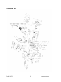
Table of Contents
Technical data……………………………………………………………………….
General safety rules………………………………………………………………….
Specific safety rules for belt/disc sanders…………………………………………...
Electrical information………………………………………………………………..
Know your belt/disc sander………………………………………………………….
Assembly and adjustments…………………………………………………………. .
Operation…………………………………………………………………………….
Maintenance………………………………………………………………………….
Exploded view…………….…………………………………………………………
Parts list……………………………………………………………………………...
Warranty……………………………………………………………………………...
2
3
5
7
9
10
16
18
19
20
21
Technical data
WEN 4” x 6” Belt/Disc Sander
Model:
Motor:
Speed:
6501
120 V, 60 Hz, 3.5 A
Disc:
Belt:
Belt size:
Belt bed tilt:
Belt table tilt:
Disc diameter:
Disc table size:
Disc table tilt:
Net weight:
1780 RPM
1150 FPM
4" x 36", 80 Grit
0–90°
45–90°
6"
7-1/2" x 5"
0–45°
34 lb
Model: 6501
2
wenproducts.com
General safety rules
Safety is a combination of common sense, staying alert, and knowing how your belt/disc sander
works. SAVE THESE SAFETY INSTRUCTIONS.
WARNING: To avoid mistakes that could cause serious injury, do not plug in the sander
until the following steps have been read and understood.
1. READ and become familiar with this entire instruction manual. LEARN the tool’s applications,
limitations, and possible hazards.
2. AVOID DANGEROUS CONDITIONS. Do not use power tools in wet or damp areas or expose
them to rain. Keep work areas well-lit.
3. DO NOT use power tools in the presence of flammable liquids or gases.
4. ALWAYS keep your work area clean, uncluttered, and well-lit. DO NOT work on floor
surfaces that are slippery.
5. KEEP BYSTANDERS AT A SAFE DISTANCE from the work area, especially when the tool
is operating. NEVER allow children or pets near the tool.
6. DO NOT FORCE THE TOOL to do a job for which it was not designed.
7. DRESS FOR SAFETY. Do not wear loose clothing, gloves, neckties, or jewelry (rings, watches,
etc.) when operating the tool. Inappropriate clothing and items can get caught in moving parts
and draw you in. ALWAYS wear non-slip footwear and tie back long hair.
8. WEAR A FACE MASK OR DUST MASK as the sanding operation produces dust.
WARNING: Dust generated from certain materials can be hazardous to your health. Always
operate this tool in a well-ventilated area and provide for proper dust removal. Use dust collection
systems whenever possible.
9. ALWAYS remove the power cord plug from the electrical outlet when making adjustments,
changing parts, cleaning or working on the tool.
10. KEEP GUARDS IN PLACE AND IN WORKING ORDER.
11. AVOID ACCIDENTAL START-UPS. Make sure the power switch is in the OFF position
before plugging in the power cord.
12. REMOVE ADJUSTMENT TOOLS. Always make sure all adjustment tools are removed from
the sander before turning it on.
Model: 6501
3
wenproducts.com
General safety rules (continued)
13. NEVER LEAVE A RUNNING TOOL UNATTENDED. Turn the power switch to OFF. Do
not leave the tool until it has come to a complete stop.
14. NEVER STAND ON A TOOL. Serious injury could result if the tool tips or is accidentally hit.
DO NOT store anything above or near the tool.
15. DO NOT OVERREACH. Keep proper footing and balance at all times. Wear oil-resistant
rubber-soled footwear. Keep the floor clear of oil, scrap, and other debris.
16. MAINTAIN TOOLS PROPERLY. ALWAYS keep tools clean and in good working order.
Follow instructions for lubricating and changing accessories.
17. CHECK FOR DAMAGED PARTS. Check for alignment of moving parts, jamming, breakage,
improper mounting, or any other conditions that may affect the tool’s operation. Any part that is
damaged should be properly repaired or replaced before use.
18. MAKE THE WORKSHOP CHILDPROOF. Use padlocks and master switches and ALWAYS
remove starter keys.
19. DO NOT operate the tool if you are under the influence of drugs, alcohol, or medication that
could affect your ability to use the tool properly.
20. USE SAFETY GOGGLES AT ALL TIMES—that comply with
ANSI Z87.1. Normal safety glasses only have impact resistant
lenses and are not designed for safety. Wear a face or dust mask
when working in a dusty environment. Use ear protection, such
as plugs or muffs, during extended periods of operation.
Model: 6501
4
wenproducts.com
Specific safety rules for belt/disc sanders
WARNING: Do not operate this tool until it is completely assembled and installed
according to the instructions.
1. This sander is designed to sand wood or wood-like products only. Sanding or grinding other
materials could result in fire, injury, or damage to the workpiece.
2. Use the sander on horizontal surfaces only. Operating the sander when mounted on nonhorizontal surfaces might result in motor damage.
3. Fasten the sander securely to a bench top or supporting surface in order to stop it from tipping
over or moving when in use.
4. 4. Make sure the sanding belt is installed in the correct direction. See directional arrow on back
of belt.
5. Always have the tracking adjusted properly so the belt does not run off the pulleys.
6. Do not use sanding belts or discs that are damaged, torn, or loose. Use only correct size sanding
belt and disc.
7. 7. Always hold the workpiece firmly when sanding. Keep hands away from sanding belt or disc.
Sand only one workpiece at a time.
8. 8. Always hold the workpiece firmly on the table when using the disc sander and when using
the belt sander.
9. 9. Always sand on the downward side of the sanding disc when using the disc sander. Sanding
on the upward side of the disc could cause the workpiece to fly out of position, resulting in
injury.
10. 10. Always maintain a minimum clearance of 1/16 inch (1.6 mm) or less between the table or
backstop and the sanding belt or disc.
11. 11. Do not sand pieces of material that are too small to be safely supported.
12. 12. When sanding a large workpiece, provide additional support at table height.
Model: 6501
5
wenproducts.com
Specific safety rules for belt/disc sanders (continued)
13. Do not sand with the workpiece unsupported. Support the workpiece with the backstop or table.
The only exception is curved work performed on the outer sanding drum.
14. Always remove scrap pieces and other objects from the table, backstop, or belt before turning
the sander ON.
15. Never perform layout, assembly or set-up work on the table while the sander is operating.
16. Never use solvents to clean plastic parts. Solvents could dissolve or otherwise damage the
material. Use only a soft damp cloth to clean plastic parts.
17. Should any part of your sander be missing, damaged, or fail in any way, or any electrical
components fail to perform properly, shut off switch and remove plug from power supply outlet.
Replace missing, damaged, or failed parts before resuming operation.
18. Never pull the power cord out of the receptacle. Keep cords away from heat, oil, and sharp
edges.
19. Have an electrician replace or repair damaged or worn cords immediately.
Model: 6501
6
wenproducts.com
Electrical information
Grounding instructions
IN THE EVENT OF A MALFUNCTION OR BREAKDOWN, grounding provides the path of
least resistance for electric current and reduces the risk of electric shock. This tool is equipped with
an electric cord that has an equipment grounding conductor and a grounding plug. The plug MUST
be plugged into a matching outlet that is properly installed and grounded in accordance with ALL
local codes and ordinances.
DO NOT MODIFY THE PLUG PROVIDED. If it will not fit the outlet, have the proper outlet
installed by an electrician.
IMPROPER CONNECTION of the equipment grounding conductor can result in electric shock.
The conductor with the green insulation (with or without yellow stripes) is the equipment
grounding conductor. If repair or replacement of the electric cord or plug is necessary, DO NOT
connect the equipment grounding conductor to a live terminal.
CHECK with a licensed electrician or service personnel if you do not completely understand the
grounding instructions, or if you are not sure if the tool is properly grounded.
USE ONLY THREE-WIRE EXTENSION CORDS that have 3-pronged plugs and outlets that
accept the tool's plug as shown in Fig. A. Repair or replace a damaged or worn cord immediately.
CAUTION: In all cases, make certain the outlet in question is properly grounded. If you are not
sure if it is, have a licensed electrician check the outlet.
Model: 6501
7
wenproducts.com
Electrical information (continued)
Guidelines for using extension cords
WARNING: This tool is for indoor use only. Do not expose to rain or use in damp locations.
Make sure your extension cord is in good condition. When using an extension cord, be sure to use
one heavy enough to carry the current your product will draw. An undersized cord will cause a drop
in line voltage resulting in loss of power and overheating. The table below shows the correct size to
be used according to cord length and nameplate ampere rating. If in doubt, use the next heavier
gauge. The smaller the gauge number, the heavier the cord.
Minimum gauge for Extension Cords (AWG)
(When using 120V only)
Ampere Rating
Total Length of Cord in feet
More Than Not More Than
25
50
100
150
0
6
18
16
16
14
6
10
18
16
14
12
10
12
16
16
14
12
12
16
14
12
Not Recommended
Be sure your extension cord is properly wired and in good condition. Always replace a damaged
extension cord or have it repaired by a qualified person before using it.
Protect your extension cords from sharp objects, excessive heat and damp or wet areas.
Use a separate electrical circuit for your tools. This circuit must not be less than a #12 wire and
should be protected with a 15 A time-delayed fuse. Before connecting the motor to the power line,
make sure the switch is in the OFF position and the electric current is rated the same as the current
stamped on the motor nameplate. Running at a lower voltage will damage the motor.
WARNING: This tool must be grounded while in use to protect the operator from electrical
shock.
Model: 6501
8
wenproducts.com
Know Your Belt/Disc Sander
Unpacking
WARNING: To avoid injury from accidental starting, turn switch OFF and remove plug
from power source outlet before making any adjustments.
Carefully unpack the belt/disc sander and all its parts, and compare against the list below. Do not
discard the carton or any packaging until the belt/disc sander is completely assembled. If any parts
are missing or broken, please call our customer service at (888) 315-3080.
1
2
3
10
Machine body
Table
Disc cover
Wrench
4 Stop plate
5 Front cover
6 Rubber pad(4)
7 Miter gauge
8 Aluminum disc
9 Allen wrench
Not shown:
1-6” Sanding Disc
1-4” x 36” Sanding Belt (assembled on machine)
Model: 6501
9
wenproducts.com
Assembly and adjustments
Feet Placement
1.
2.
Carefully set the Belt/Disc Sander on its side.
Press each Rubber Pad (28) over the lip of the Base at each corner.
(See Figure 1)
Mounting Aluminum Disc and installing a Sanding Disc
1.
Use a screwdriver to loosen the 3 screws on the top side of outer
pulley cover. (Figure 2)
2.
Align the 3 holes on the disc cover with the 3 holes on the outer
pulley cover, and fasten the disc cover on the outer pulley cover
by 3 screws. (Figure 3)
3.
Place the Aluminum Disc on the drive shaft. Align the flat face
of the drive shaft with the set screw in the hub of the Aluminum
Disc. Fasten set screw with the Allen Wrench provided through
the hole on the top of the Disc cover. (Figure 4)
Figure 3
Model: 6501
10
wenproducts.com
Assembly and adjustments (continued)
4.
Peel sanding disc adhesive backing. Align perimeter of new sanding disc over the Aluminum
Disc and press firmly onto the Aluminum Disc.
NOTE: Before attaching the disc, wipe down the Aluminum Disc with denatured alcohol (shellac
thinner). This will clean the surface, leave no residue and assure a secure bond.
5.
Use a screwdriver to loosen the 4 screws on the bottom of disc
cover. (Figure 5)
6.
Align the 4 holes on the disc guard with the 4 holes on the
front cover, and fasten them together by 4 screws. (Figure 6)
Model: 6501
11
wenproducts.com
Assembly and adjustments (continued)
Mounting table for use as Disc Sander
NOTE: The Table (69) may be used as support for both horizontal and vertical applications.
1.
Slide Support Shaft (76) into Bar Holder (74) aligning
flat face of the shaft with set screws and tighten securely.
Slide Support Shaft (76) into existing hole on side of
Machine Body (33) and with wrench (not supplied),
tighten Bolt (32). (See Figure 7)
Square the table (Figure 8)
To ensure accurate end sanding, the work tables must be square to the sanding surfaces prior to
using the tables for disc sanding, belt sanding, or vertical belt sanding.
1. Adjust the table to be 90° with the sanding surface.
2. Using a combination square (not provided), place one
end on the table with the ruler end against the disc
sanding surface. Check that the table is 90° to the disc
sanding surface.
3. If the table is not 90° to the sanding surface, loosen
adjusting knob (75), adjust the table, tighten the handle
and recheck with the square.
WARNING: To avoid trapping the workpiece or fingers between the table and the sanding
disc, the table edge should be adjusted to a maximum of 1/16 inch from the sanding disc.
Model: 6501
12
wenproducts.com
Assembly and adjustments (continued)
Mounting table for use as belt sander
NOTE: The Table (69) may be used for both horizontal and vertical operations.
1.
Remove Table from Machine Body using reverse procedures in step 1 of “Mounting table for
use as disc sander” section above.
2. Set Belt/Disc Sander in vertical position by loosening both Nuts (22). Raise the Belt Support
Housing (52). When it is vertical, tighten both Nuts (22) very tight to prevent the Belt Support
Housing (52) from slipping. (See Figures 9 & 10)
3. Insert Support Shaft (76) into the hole facing the belts and tighten Bolt (32) against flat side of
Support Shaft (76). (See Figures (9 & 10)
Model: 6501
13
wenproducts.com
Assembly and adjustments (continued)
Mounting stop plate
This Stop Plate (63) fits across the top of the sanding belt
and is for preventing workpiece from moving to the rear
when sanding.
1.
2.
3.
Align the two Tabs on the Stop Plate (63) with the two
Holes on the top of the Band Support Housing (52).
The Tabs will be underneath the Flange on the Band
Support Housing (52).
Insert two Machine Screws into the two Holes and
thread them into the Tabs on the Stop Plate (63).
Mount the Stop Plate (63) to the Band Support
Housing (52) using Bolt (32), Flat Washer (26) and
Lock Washer (27). (See Figure 11)
Square the stop plate (Figure 12)
The stop plate (63) must be square to the sanding belt when using the belt sander in a horizontal
position. To keep the workpiece from being carried along
the belt:
1. Make sure the sanding belt is tight; also check that the
tension handle is fully tightened.
2. Place the combination square (not provided) on the belt
with the ruler against the stop plate (63).
3. Adjust by loosening the stop plate locking bolt (32),
square the backstop.
4. Tighten the stop plate locking bolt (32).
WARNING: To avoid trapping the workpiece or fingers between the sanding belt and the
stop plate, the stop plate edge should be adjusted to a maximum of 1/16 inch from the sanding belt.
Model: 6501
14
wenproducts.com
Assembly and adjustments (continued)
Install the sanding belt
1.
2.
3.
Push the Belt Tension Handle (50) forward to loosen the belt.
Remove Upper Guard Plate (58) by unscrewing four Screws (7).
Remove the Lower Guard Plate (60) by unscrewing the four Screws (7) that hold it to the Belt
Support Housing (52).
4. Slide the old sanding belt off the Rear Roller (56) and Front Roller (44).
5. Replace with a 4” X 36” sanding belt with the correct grit for the project you are working on.
NOTE: The larger the grit number, the smaller the grain. Use small numbered grits for cutting
and larger for smoothing and finishing.
6. Slide new sanding belt onto Front and Rear Rollers. Make sure the direction of the sanding belt
matches the direction of the belt rotation.
7. Replace the Lower Guard Plate (60) and tighten the four Screws (7) securely.
8. Replace the Upper Guard Plate (58) and tighten the four Screws (7).
9. Push the Belt Tension Handle (50) to the rear to tighten the belt.
10. Before using, check the new belt for alignment. See next section for detail.
Sanding belt tracking adjustment
1.
2.
Plug in the power cord.
Turn the switch ON and OFF to make sure the sanding belt is correctly centered and not sliding
off the Front and Rear Rollers (44 and 56).
3. If the belt looks like it is going to slide off either roller, it needs to be adjusted.
4. Turn the Belt Adjustment Knob (49) until the belt rides the center of the Rear Roller (56) and
the Front Roller (44).
5. Turn the switch ON and OFF again; readjust the Belt Adjustment Knob (49) if necessary.
Install a sanding disc
1.
2.
3.
4.
Remove the Table (69), if it is mounted in front of the sanding disc.
Remove the Front Cover (3).
Peel off old sanding disc.
Peel new Sanding Disc adhesive backing. Align perimeter of new sanding disc over the
Aluminum Disc (5) and press firmly onto the Aluminum Disc (5).
NOTE: If you are using the sanding disc for the first time. Before attaching the disc, wipe down the
Aluminum Disc (5) with denatured alcohol (shellac thinner). This will clean the surface, leave no
residue and assure a secure bond.
Model: 6501
15
wenproducts.com
Operation
ON/OFF switch (Figure 13)
The keyed switch is intended to prevent unauthorized use of the sander.
WARNING: Remove the safety key whenever the sander is not in use. Place the key in a
safe place and out of the reach of children.
1. To turn sander ON, insert the safety key into the
key slot in the center of the switch.
2. Push key firmly into the slot, then push switch to
the ON position to start the sander.
3. To turn the sander OFF push switch to the OFF
position.
4. Remove the safety key when the sander has come
to a complete stop by gently pulling it forward
and out.
Surface or edge sanding on sanding belt (Figure 14)
Hold the workpiece firmly with both hands. Keep
fingers away from sanding belt. Keep the workpiece
end against the backstop and move it slowly across the
sanding belt. Apply enough pressure to remove
material; excessive pressure will reduce sanding
efficiency.
Model: 6501
16
wenproducts.com
Operation (continued)
Sanding inside curves (Figure 15)
Sanding the inside curve of the workpiece is done by
positioning the workpiece on the idler pulley of the sanding
belt. Hold workpiece firmly with both hands.
End sanding and outside curve sanding with the disc (Figure 16)
Use for sanding the ends of small and narrow workpieces
and outside curved edges. Always work on the left side of
the disc (downward rotation side), holding the workpiece
firmly with light pressure against the sanding disc.
Note: Always maintain a maximum of 1/16” clearance
between the Table and sanding disc.
CAUTION: To avoid personal injury and/or damage to the workpiece, become familiar with the
rotation of the belt and disc sanding surfaces.
The belt sander rotates counterclockwise or downward toward the table or stop plate. The disc
sander rotates counterclockwise, downward toward the table on the left side of the disc and upward
from the table on the right side of the disc. Always use the left side of the disc; using the right side
of the disc will cause the workpiece to fly up or kickback and could result in injury. Review this
instruction manual for correct operation, adjustments, and basic sanding operations.
CAUTION: When finished with Belt/Disc Sander, to prevent accidents, turn off and disconnect its
power supply after use. Remove the safety Key from the Switch (31). Wipe down and store the
Sander indoors out of children’s reach.
Model: 6501
17
wenproducts.com
Maintenance
WARNING: For your own safety, turn the switch OFF and remove the plug from the
electrical outlet before adjusting or performing maintenance or lubrication work on the belt/disc
sander.
Before using, check to make sure parts are not damaged, missing, or worn; check for alignment of
moving parts, binding of moving parts, improper mounting, or any other conditions that may affect
the sander operation. Should any of these conditions exist, do not use the sander until properly
repaired or parts are replaced. Frequently blow or vacuum dust from all sanding parts and motor
housing.
WARNING: Any attempt to repair or replace electrical parts on this tool may be hazardous.
Repairs should be done by a qualified service technician.
Lubrication
Ball bearings are grease packed at the factory and require no further lubrication. Sleeve bearings on
both ends of the idler pulley should be oiled with 3 drops of 30 weight oil after each 10 hours of
operation. Use a spray lubricant on all moving table parts to ensure smooth operation.
Adjust the Drive belt tension
1. Remove Set Screws (6) and pull off Aluminum Disc (5).
2. Remove four Screws (11) and Washers (10) from Outer Pulley Cover (9).
3. Loosen four Motor Mount Nuts (22) and slide the Motor (40) further forward towards Front
Roller (44), making sure to pull evenly on the motor. While holding the motor in its current
position, tighten the Nuts (22).
4. Place a straight edge on the faces of the two pulleys to ascertain alignment. Contact surfaces of
the pulleys and the straight edge shall fully touch. Fully tighten the Nuts (22).
Model: 6501
18
wenproducts.com
Exploded view
Model: 6501
19
wenproducts.com
Parts list
Item #
1
2
3
4
5
6
7
8
9
10
11
12
13
14
15
16
17
18
19
20
21
22
23
24
25
26
27
28
29
30
31
32
33
34
35
36
37
38
Part #
6501-001
6501-002
6501-003
6501-004
6501-005
6501-006
6501-007
6501-008
6501-009
6501-010
6501-011
6501-012
6501-013
6501-014
6501-015
6501-016
6501-017
6501-018
6501-019
6501-020
6501-021
6501-022
6501-023
6501-024
6501-025
6501-026
6501-027
6501-028
6501-029
6501-030
6501-031
6501-032
6501-033
6501-034
6501-035
6501-036
6501-037
6501-038
Model: 6501
Description
Screw M4 X 12
Flat Washer 4
Front Cover
Sander Disc
Aluminum Disc
Set Screw
Screw M4 X 8
Disc Cover
Outer Pulley Cover
Washer
Screw M4 X 8
V-Belt
Motor Pulley
Spindle Pulley
Screw M8 X 6
Bolt M6 X 12
Lock Washer
Flat Washer
Screw M5 X 20
Inner Pulley Cover
Spacer
Nut 8
Supporting Rod
Nut 10
Base
Flat Washer 8
Lock Washer 8
Rubber Pad
Screw M5 X 12
Flat Washer 5
ON/OFF Switch
Bolt M8 X 16
Machine Body
Rubber Cap
Steel Plate
Holding Plate
Cable Fixing Plate
Hold Plate Bolt
Qty
9
27
1
1
1
1
14
1
1
16
6
1
1
1
2
6
7
7
3
1
1
6
1
1
1
9
8
4
5
5
1
8
1
1
1
1
1
1
Item #
39
40
41
42
43
44
45
46
47
48
49
50
51
52
53
54
55
56
57
58
59
60
61
62
63
64
65
66
67
68
69
70
71
72
73
74
75
76
20
Part #
6501-039
6501-040
6501-041
6501-042
6501-043
6501-044
6501-045
6501-046
6501-047
6501-048
6501-049
6501-050
6501-051
6501-052
6501-053
6501-054
6501-055
6501-056
6501-057
6501-058
6501-059
6501-060
6501-061
6501-062
6501-063
6501-064
6501-065
6501-066
6501-067
6501-068
6501-069
6501-070
6501-071
6501-072
6501-073
6501-074
6501-075
6501-076
Description
Rubber Tube
Motor
Washer 5
Retaining Ring 12
Ball Bearing
Front Roller
Adjusting Bracket
Spring
Shaft
Spring
Belt Adjustment Knob
Belt Tension Handle
Screw M6 X 12
Belt Support Housing
Coach Bolt M8 X 35
Drive Shaft
Bearing Housing
Rear Roller
Left Bearing Housing
Upper Guard Plate
Dust Port
Lower Guard Plate
Screw
Belt Sander
Stop Plate
Knob M5 X 16
Miter Gauge
Screw M5 X 6
Pointer
Sliding Bar
Table
Pivot Indicator
Hex Bolt M8 X 10
Table Bar
Angle Pointer
Bar Holder
Adjusting Knob
Supporting Shaft
wenproducts.com
Qty
1
1
4
2
4
1
1
1
1
1
1
1
1
1
2
1
1
1
1
1
1
1
3
1
1
1
1
1
1
1
1
1
1
1
1
1
1
1
Warranty
WEN Products warrants its power tools to be free of defects from materials and workmanship for a
period of one (1) year from date of original purchase. We will repair or replace, at our option, any
tool covered by this warranty that after inspection is found to be defective in materials or
workmanship during the warranty period. If the product is used for commercial, professional or
income producing purposes, the limited warranty period is 90 days. The limited warranty period is
30 days when the product is used for rental purposes.
This limited warranty applies only to the original owner and is not transferable to subsequent
owners. The limited warranty begins on the date of purchase by the original owner and extends for
the fore-mentioned time periods. This limited warranty does not apply if the tool has been misused,
abused, subject to an accident, altered or repaired by others not authorized. Normal wear and tear is
also not covered by this warranty.
To take advantage of this warranty, please contact us at 1-888-315-3080 or write to us at WEN. PO
Box 1110, Dundee, IL 60118. You will need proof of purchase and may be asked to ship the tool
back to us freight prepaid.
Under no circumstances shall WEN Products be liable for any indirect, incidental or consequential
damages from the sale or use of this product. Some states do not allow the exclusion or limitation
of incidental or consequential damages. Some states do not allow limitations on the length of an
implied warranty. This warranty provides you with specific legal rights and you may have other
rights that vary from state to state.
Model: 6501
21
wenproducts.com