1
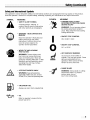
Operator's Manual
Model
IMPORTANT:
CC 3075
READ SAFETY RULES AND INSTRUCTIONS
P/N 769-00876 (10/03)
PRINTED IN USA
CAREFULLY
Table of Contents
Content
Page
Section 1: Safety ...........................................................
Section 2: Know Your Unit ...................................................
3
6
Section 3: Assembly ........................................................
Section 4: Oil and Fuel ......................................................
7
8
Section 5: Operation ..................................................
Section 6: Maintenance .....................................................
9
12
Section 7: Troubleshooting
.................................................
Section 8: Specifications ...............................................
Warranty Information .........................................................
18
19
To the Owner
Thank you for buying this quality product. This modern outdoor power tool will provide many hours of useful service. You
will find it to be a great labor-saving device. This operator's manual provides you with easy-to-understand operating
instructions. Before starting or operating this equipment, read the whole manual and follow all the instructions to keep
your new outdoor power tool in top operating condition.
All information, illustrations and specifications in this manual are based on the latest product information available at the
time of printing. We reserve the right to make changes at any time without notice. Service on this unit both within and
after the warranty period should be performed only by a Cub Cadet dealer. Proof of purchase will be required for
warranty service.
NOTE: For users on U.S. Forest Land and in the states of California, Maine, Oregon and Washington. All U,S: Forest Land and the state of
California (Public Resources Codes 4442 and 4443), Oregon and Washington require, by law that certain internal combustion engines operated
on forest brush andlor grass-covered
areas be equipped with a spark arrestor, maintained
in effective working order, or the engine be
constructed, equipped and maintained for the prevention of fire. Check with your state or local authorities for regulations pertaining to these
requirements. Failure to follow these requirements could subject you to liability or a fine, This unit is factory equipped with a spark arrestor. If
it requires replacement, Accessory Part #181696 Spark Arrestor Screen is available by contacting the service department.
Finding the Model Number
Before you start assembling your new equipment, please locate the model plate on the equipment and copy the
information from it in the space provided below. This information is very important if you need help from our Customer
Support Department or an authorized dealer.
Model Humber
Parent Pert Humber
Copythe mode!and parentpart
numberhere:
SiN :
ITEM :
IIIIIIIIIllllllllllHIIInllHIlllll
the seria!numberhere:
Calling Customer Sunnort
If you have difficulty assembling this product or have any questions regarding the controls, operation or maintenance of
this unit, please call the Customer Support Department.
@
Call 1-877-282-8684 to reach a Customer Support representative. Please have your unit's model number
and serial number ready when you call. See the previous section to locate this information.
Copyright© 2003 Cub Cadet LLC
All Rights Reserved
2
Section 1
Safety
The purpose of safety symbols is to attract your attention to possible dangers. The safety symbols, and the r
explanations, deserve your careful attention and understanding. The safety warnings do not by themselves eliminate
]
|
any danger. The instructions or warnings they give are not substitutes for proper accident prevention measures.
/
SYMBOL
_1_
,AI,
MEANING
]
I SAFETY ALERT SYMBOL: Indicates danger,
I warning or caution. Attention is required in I
order to avoid serious personal injury. May
be used in conjunction with other symbols
or pictographs.
I
NOTE: Advises you of information or instructions
vital to the operation or maintenance of the
equipment.
Failure to obey a safety warning will result in
serious injury to yourself or to others. Always
follow the safety precautions to reduce the risk of
fi_d
ersonal iniur .
Failure to obey a safety warning can result in
injury to yourself and others. Always follow the
safety precautions to reduce the risk of fire,
electric shock, and personal injury.
California Proposition65 Warning
THE ENGINE EXHAUST FROM THIS PRODUCT
CONTAINS CHEMICALS KNOWN TO THE STATE OF
CALIFORNIA TO CAUSE CANCER, BIRTH DEFECTS
OR OTHER REPRODUCTIVE HARM.
Failure to obey a safety warning may result in property
damage or personal injury to yourself or to others.
Always follow the safety precautions to reduce the
risk of fire, electric shock, and personal injury.
Important Safety Information
READALL INSTRUCTIONS
Before Operating
• Read the instructions carefully. Be familiar with the
controls and proper use of the unit.
• Do not operate this unit when tired, ill or under the
influence of alcohol, drugs or medication.
• Children and teens under the age of 15 must not use
the unit, except for teens guided by an adult.
• Inspect the unit before use. Replace damaged parts.
Check for fuel leaks. Make sure all fasteners are in
place and secure. Replace cutting attachment parts
that are cracked, chipped or damaged in any way.
Make sure the cutting attachment is properly installed
and securely fastened. Be sure the cutting attachment
shield is properly attached, and positioned as
recommended. Failure to do so can result in personal
injury to the operator and bystanders, as well as
damage to the unit.
• Be aware of the risk of injury to the head, hands and
feet.
• Use only 0.105 inch (2.67 mm) diameter original
equipment manufacturer replacement line. Never use
metal-reinforced line, wire or rope. These can break
off and become dangerous projectiles.
• Clear the area to be cut before each use. Remove all
objects such as rocks, broken glass, nails, wire or
string. They can be thrown or become entangled in the
cutting attachment. Clear the area of children,
bystanders, and pets. At a minimum, keep all children,
bystanders and pets outside a 50-foot (15 m.) radius;
there still may be a risk to bystanders from thrown
objects. Bystanders should be encouraged to wear
eye protection. If you are approached, stop the engine
and cutting attachment immediately.
• Squeeze the throttle control and check that it returns
automatically to the idle position. Make all adjustments
or repairs before using unit.
Safet)
Safety Warnings for Gas Trimmers
• Use the right toot. Only use this tool for the purpose
intended.
• Do not overreach. Always keep proper footing and
balance.
Gasoline is highly flammable, and its vapors can
explode if ignited. Take the following precautions.
• Store fuel only in containers specificalIy designed and
approved for the storage of such materials.
• Always stop the engine and allow it to cool before
filIing the fuel tank. Never remove the cap of the fuel
tank, or add fuel, when the engine is hot. Never
operate the unit without the fuet cap securely in piace.
Loosen the fuet tank cap slowly to relieve any pressure
in the tank.
• Add fuel in a clean, well-ventilated outdoor area where
there are no sparks or flames. Slowly remove the fuel
cap only after stopping engine. Do not smoke while
fueling or mixing fuel. Wipe up any spilled fuet from the
unit immediately.
• Avoid creating a source of ignition for spilled fuel. Do
not start the engine until fuel vapors dissipate.
• Move the unit at least 30 feet (9.1 m) from the fueling
source and site before starting the engine. Do not
smoke. Keep sparks and open flames away from the
area while adding fuet or operating the unit.
While Operating
• Never start or run the unit inside a closed room or
building. Breathing exhaust fumes can kill. Operate
this unit only in a welt ventilated outdoor area.
• Wear safety gtasses or goggles that are marked as
meeting ANSI Z87.1-1989 standards. Also wear
ear/hearing protection when operating this unit. Wear
a face or dust mask if the operation is dusty. Long
sleeve shirts are recommended.
• Always hold the unit with both hands when operating.
Keep a firm grip on both the front and rear handle or
grips.
• Keep hands, face, and feet at a distance from alI
moving parts. Do not touch or try to stop the cutting
attachment when it is rotating.
• Do not touch the engine or muffler. These parts get
extremely hot from operation. They remain hot for a
short time after you turn off the unit.
• Do not operate the engine faster than the speed
needed to cut, trim or edge. Do not run the engine at
high speed when you are not cutting.
• Always stop the engine when cutting is delayed or
when walking from one cutting tocation to another.
• If you strike or become entangled with a foreign
object, stop the engine immediately and check for
damage. Do not operate before repairing damage. Do
not operate the unit with loose or damaged parts.
• Stop and switch the engine to off for maintenance,
repair, or for changing the cutting attachment or other
attachments.
Use only original equipment manufacturer
replacement parts and accessories for this unit. These
are available from your authorized service dealer. Use
of any unauthorized parts or accessories could lead to
serious injury to the user, or damage to the unit, and
void your warranty.
• Keep unit clean of vegetation and other materials.
They may become lodged between the cutting
attachment and shield.
• To reduce fire hazard, replace faulty muffler and spark
arrestor, keep the engine and muffler free from grass,
leaves, excessive grease or carbon build up.
• Wear heavy, tong pants, boots and gloves. Do not
wear ioose clothing,jewelry,
short pants, sandals or
go barefoot. Secure hair above shoulder ievet.
Other Safety Warnings
• The cutting attachment shield must always be in place
white operating the unit. Do not operate unit without
both trimming tines extended, and the proper line
installed. Do not extend the trimming line beyond the
length of the shield.
• Allow the engine to coot before storing or transporting.
Be sure to secure the unit white transporting.
• [his unit has a clutch. The cutting attachment remains
stationary when the engine is idling. If it does not, have
the unit adjusted by an authorized service technician.
• Adjust the D-handle to your size to provide the best
grip.
• Be sure the cutting attachment is not in contact with
anything before starting the unit.
• Use the unit only in daylight or good artificial light.
• Avoid accidental starting. Be in the starting position
whenever pulling the starter rope. The operator and
unit must be in a stable position while starting. See
Starting/Stopping Instructions.
4iiiiiiii
• Never store the unit, with fuel in the tank, inside a
building where fumes may reach an open flame or
spark.
• Store the unit in a dry area, locked up or up high
to prevent unauthorized use or damage, out of the
reach of children.
• Never douse or squirt the unit with water or any other
liquid. Keep handles dry, clean and free from debris.
Clean after each use. See the Cleaning and Storage
instructions.
• Keep these instructions. Refer to them often and use
them to instruct other users, tf you toan someone this
unit, also loan them these instructions.
SAVETHESEINSTRUCTIONS
Safety and International Symbols
lhis operator's manuaI describes safety and international symbols and pictographs that may appear on this product.
Read the operator's manual for complete safety, assembly, operating and maintenance and repair information.
SYMBOL
MEANING
SYMBOL
• SAFETY ALERT SYMBOL
indicates danger, warning, or
caution. May be used in conjunction
with other symbols or pictographs.
©
WARNING - READ OPERATOR'S
MANUAL
Read the OperatoFs ManuaI(s) and
follow all warnings and safety
instructions. Failure to do so can
resuIt in serious injury to the
operator and/or bystanders.
-_
MEANING
* THROWN OBJECTS AND
ROTATING CUTTER CAN CAUSE
SEVERE INJURY
WARNING: Do not operate without
the cutting attachment shield in
place. Keep away from the rotating
cutting attachment.
ON / START/RUN
* ON/OFF STOP CONTROL
* ON1OFF
STOP CONTROL
OFF or STOP
WEAR EYE AND HEARING
PROTECTION
WARNING: Thrown objects and
loud noise can cause severe eye
injury and hearing loss. Wear eye
protection meeting ANSI Z87.1-1989
standards and ear protection when
operating this unit. Use a full face
shield when needed.
HOT SURFACE WARNING
DO not touch a hot muffler or
cylinder. You may get burned. These
parts get extremely hot from
operation. When turned off they
remain hot for a short time.
SHARP BLADE
KEEP BYSTANDERS AWAY
WARNING: Keep all bystanders,
especially children and pets, at least
50 fe_t (15 m.) from the operating area.
• UNLEADED
FUEL
Always use clean, fresh unleaded fuel.
• OIL
Refer to operator's
proper type of oil.
manual for the
WARNING: Sharp blade on cutting
attachment shield. To prevent
serious injury, do not
touch line cutting blade.
Section 2
KnowYourUnit
Applications
With the optional brushcutter accessory kit:
As a trimmer:
Cutting weeds and light bush of up to 1/2 inch in diameter
Cutting grass and light weeds
Spark Plug.
Edging
Starter Rope Grip
/
Decorative trimming around trees, fences, etc.
Fuel Cap
Throttle
Control
Support Fitting ......
On/Off Stop Control
Air Filter Cover
EZ-Link _
/
•
/
f
/
/
Shaft Housing
Choke Lever
/
Primer Bulb
i'
Cutting Attachment
Shield
Line Cutting Blade
Cutting Attachment
6iiiiiiiiiiiiiiiiii
Section 3
Assembly
Install and Adjust the D-handle
Shaft Grip
(4) Screws =_
Shaft
Housing
_
_1_
==
==
1.
Remove the screws and bottom ciamp piece that
were installed on the D-handle for shipping.
2.
Place D-handle over the shaft housing and onto the
bottom clamp (Fig. 3-1). Place it a minimum of 6
inches (15.24 cm) from the end of the shaft grip.
3.
Start screws with a large Fiat-head or T-25 Torx
screwdriver. Do not tighten until you make the
handle adjustment.
4.
If it was pre-installed, loosen the screws on the
D-handlejust enough to move the D-handle.
=,
Minimum 6 inches
(15i24 cm)
D-Handle
Bottom Clamp
(4) Nuts .......
Fig, 3-1
5. While holding the unit in the operating position
(Fig. 3-2), move the D-handle to the location that
provides you the best grip.
6. lighten the clamp screws evenly, until the D-handle
is secure.
(if used)
Fig. 3-2
¸¸¸¸¸¸¸¸¸¸¸¸¸¸¸¸¸¸¸¸7¸
Section 4
Oiland Fuel
For proper engine operation and maximum
reliability, pay strict attention to the oil and fuel
mixing instructions on the 2-cycle oil container.
Using improperly mixed fuel can severely damage
the engine.
UNLEADED GAS
°
i GALLON US
MIXING RATIO
2 C¥CI-E OI13i2 FL OZ
(95 _i1
Thoroughly mix the proper ratio of 2-cycle engine oil
with unleaded gasoline in a separate fuel can. Use a 40:1
fuel/oit ratio. Do not mix them directly in the engine fuet
tank. See the table below for specific gas and oit mixing
ratios.
40:1
Oil and Fuel Mixing Instructions
Old and/or improperly mixed fuel are the main reasons
for the unit not running properly. Be sure to use fresh,
dean unteaded fuel. Foilow the instructions carefully for
the proper fuelioiI mixture.
Definition of Blended Fuels
Today's fuels are often a blend of gasoline and
oxygenates such as ethanol, methanol, or M1BE (ether).
AIcohol-blended fuet absorbs water. As little as 1%
water in the fuel can make fuel and oil separate, it forms
acids when stored. When using alcohol-blended fuel,
use fresh fuet (less than 60 days old).
Using Blended Fuels
NOTE: One gallon (3.8 liters) of unleaded gasoline
mixed with one 3.2 oz. (95 m/) bottle of
2-cycle off makes a 40:1 fuel/off ratio.
Gasoline is extremely flammable. Ignited Vapors
may explode. Always stop the engine and allow it
to cool before filling the fuel tank. Do not smoke
while filling the tank. Keep sparks and open flames
at a distance from the area.
Remove fuel cap slowly to avoid injury from fuel
spray. Never operate the unit without the fuel cap
securely in place.
if you choose to use a blended fuel, or its use is
unavoidable, follow recommended precautions:
• Atways use the fresh fuel mix explained in your
operator's manual
•AIways
agitate the fuei mix before fueling the unit
• Drain the tank and run the engine dry before storing
the unit
Using Fuel Additives
lhe bottie of 2-cycte oil that came with your unit
contains a fuel additive which wiii help inhibit corrosion
and minimize the formation of gum deposits, it is
recommended that you use our 2-cycle oil with this unit.
if unavaiIable, use a good 2-cycle oil designed for
air-cooled engines aIong with a fuel additive, such as
STA-BIU _ Gas Stabilizer or an equivalent. Add 0.8 oz.
(23 mt.) of fuet additive per gallon of fuel according to the
instructions on the container. NEVER add fuel additives
directly to the unit's fuel tank.
8iiiiiiiiiiiiiiiiii
Add fuel
Wipe up
creating
start the
in a clean, well ventilated area outdoors.
any spilled fuel immediately.
Avoid
a source of ignition for spilt fuel. Do not
engine until fuel vapors dissipate.
NOTE: Dispose of the old fuel/off mix in accordance
to Federal, State and Local regulations.
Section 5
Operation
P)iii
OperateithisunitQn_inawe!!_venti!atedo_doQrar_i
carbonmonoxideexhaustfumescanbelethal;ina
c_nfinediiareaiiiiiiiiiiiiiiiiiiiiiiiiiiiiiiiiiiiiiiiiiiiiiiiiiiiiiiiiiiiiiiiiiiiiiiiiiiiiiiiiiiiiiiiiiiiiiiiiiiiiiiiiiiiiiiiiiiiiiiiiiiiiiiiiiiiiiiiiiiiiiiiiiiiiiiiii
m
_
w
On/Off
Avoid ac_idental startingi Make sure you are in the
S_rting positi_n when puiiing the sta_er rope (Figi s_3) i
To avoid serious injury, the operator and unit must be
inastable
poSit iO_ Whiie start in9
Make SUre that a_ add;-On item is instalied €orrectly and
secure before stalin
the Unit
Stop Control
1: Mix gas with eli2 Fitl fuei tank with fUeiloil miXtUre: See
Oil and Fue! Mix#Tg Instructions.
2.
Make sure the On/Off Stop Control in the ON (I)
position (Fig. 5-1).
Fully press and release the primer bulb 10 times,
slowty. Some amount of fuel should be visible in the
primer bulb and fuel tines (Fig. 5-2). if you can't see
fuel in the bulb, press and release the butb as many
times as it takes before you can see fuel in it.
4.
Place the choke lever in Position 1 (Start} (Fig. 5-2).
5.
With the unit in the starting position (Fig. 5-3), squeeze
the throttle control to the wide open (fuji throttle)
position. Pull the starter rope briskly 5 times.
6.
Place the choke lever in Position 2 (Run).
7.
While squeezing the throttle controi, pull the starter
rope briskly 1 to 3 times to start the engine.
8.
Keep the throttle squeezed and allow the engine to
warm up for 15 to 30 seconds. The unit is ready for use.
Starter Rope
',_-_ IF,,, The engine does not start, go back to step 3.
IE.,
The engine fails to start after a couple attempts, place
the choke lever in Position 2 and squeeze the throttle
control. Pull the starter rope briskly 3 to 8 times, lhe
engine should start. If not, repeat.
tF WARM,,,
if the engine is already warm, make sure
the On/Off Stop control is in the ON position and
start the unit with the choke lever in Position 2.
StoppingInstructions
1.
Release your hand from the throttle control. Allow the engine
to coot down by idling.
2.
Put the On/Off Stop Control in the OFF (O) position.
Fig. 5-3
Throttle Control (Squeezed)
Operation(continued)
Read and understand the operator's
each add-on prior to operation.
manual for
Removing the Cutting Attachment or Add-0ns
1.
[urn the knob counterclockwise
to loosen (Fig. 5-4).
2.
Press and hold the release button (Fig. 5-4).
3. While firmly holding the upper shaft housing, puil
the cutting attachment or add-on straight out of the
EZ-Link _Mcoupier (Fig. 5-5}.
Installing the Cutting Attachment or Add-0ns
To avoid serious personal
injury and damage
to the
unit, shut unit off before removing
or installing
addons.
NOTE: To make installing or removing the add-on
easier, place the unit on the ground or on a work
bench.
1. Turn knob counterclockwise
to loosen,
2. While firmly holding the add-on, push it straight into
the EZ-Link rM coupler (Fig. 5-5).
90" Edging Hole
[Trimmer Only)
NOTE: Aligning the release button with the guide recess
will hetp installation (Fig. 5-4).
%
3.
Turn the knob clockwise to tighten (Fig. 5-6).
Lock the release button in the primary hole and
securely tighten the knob before operating this unit.
Operating the EZ-Link"* System
lhe EZ-Link rM system enabtes the use of these optionat
Add-Qns.
Cultivator
................................
TBGC
Edger ...................................
TBLE
Hedge Trimmer
TBAH
...........................
Straight Shaft Trimmer ......................
Turbo Blower .............................
TBSS
TBTB
Pole Saw ................................
TBPS
loiiiiiiiiiiii
The cutting attachment and add-ons with the EZLink TM system are to be used in the primary hole
unless stated otherwise in the specific add-ons
operator's manual. Using the wrong hole could lead
to personal injury, or damage to the unit.
For edging (when using the Iine head cutting attachment
with EZ-Link _Mmodels_, lock the release button of the
cutting attachment into the 90 ° edging hole or the 180 °
edging hole (Fig. 5-6).
Operation(continued)
Each time the head is bumped, about 1 inch (25.4 mm) of
trimming line releases. A blade in the cutting attachment
shield wiii cut the line to the proper length if any excess
line is released.
For best resuIts, tap the bump knob on bare ground or
hard soil. If you attempt a tine release in tail grass, the
engine may stall. Always keep the trimming line fully
extended. Line release becomes more difficult when the
cutting line gets shorter.
NOTE: Do not rest the Bump Head on the ground
while the unit is running.
Fig, 5-7
Do not remove or alter the line cutting blade
assembly. Excessive line length will make the
clutch overheat. This may lead to serious personal
injury or damage to the unit,
Some line breakage will occur from:
• Entanglement with foreign matter
• Normal line fatigue
• Attempting to cut thick, stalky weeds
• Forcing the tine into objects such as wails or fence
posts
Tips for Best Trimming Results
Keep the cutting attachment
Holding the Trimmer
Always wear eye, hearing, foot and body
protection to reduce the risk of injury when
operating this unit.
Before operating the unit, stand in the operating position
(Fig. 5-7). Check for the following:
The operator is wearing eye protection and proper
clothing
With a slightly-bent right arm, the operator's hand is
holding the shaft grip
The operator's Ieft arm is straight, the left hand
holding the D-handle
The unit is at waist level
The cutting attachment is paralIet to the ground and
easily contacts the grass without the need to bend over
Adjusting Trimming Line Length
lhe Bump Head cutting attachment allowsyou to release
trimming line without stopping the engine, fo release
more iine, lightly tap the cutting attachment on the ground
(Fig. 5-8) while operating the trimmer at high speed.
NOTE:
Always keep the trimming line fully
extended. Line release becomes more
difficult as cutting line becomes shorter.
parallet to the ground.
Do not force the cutting attachment. Aliow the tip of
the line to do the cutting, especially along walls.
Cutting with more than the tip wili reduce cutting
efficiency and may overload the engine.
Cut grass over 8 inches (200 ram) by working from
top to bottom in small increments to avoid premature
line wear or engine drag.
Cut from right to left whenever possible. Cutting to
the left improves the unit's cutting efficiency.
Clippings are thrown away from the operator.
Slowly move the trimmer into and out of the cutting
area at the desired height. Move either in a forwardbackward or side-to-side motion. Cutting shorter
lengths produces the best results.
Trim only when grass and weeds are dry.
The life of your cutting tine is dependent upon:
FoIIowing the trimming techniques
What vegetation is being cut
Where vegetation is cut
For example, the line wilI wear faster when trimming
against a foundation wall as opposed to trimming around
a tree.
Decorative Trimming
Decorative trimming is accomplished by removing all
vegetation around trees, posts, fences and more.
Rotate the whole unit so that the cutting attachment is at
a 30 ° angle to the ground (Fig. 5-9).
Section 6
Maintenance
Maintenance Schedule
Perform these required maintenance procedures at the
frequency statedin the table, lhese procedures should
also be a part of any seasonal tune-up.
NOTE: Some maintenance procedures may require
special tools or skills. If you are unsure about
these procedures take your unit to any nonroad engine repair establishment.
To prevent serious injury, never perform
maintenance or repairs with unit running. Always
service and repair a cool unit. Disconnect the spark
plug wire to ensure that the unit cannot start.
Before s_a_ting engine
NOTE: Maintenance, replacement
or repair of the
emission control devices and system may be
performed by any non-read engine repair
establishmen_
individual or authorized
service dealer.
In order to assure peak performance of your engine,
inspection of the engine exhaust port may be necessary
after 50 hours of operation. If you notice lost RPM, poor
performance or general lack of acceleration, this service
may be required, if you feel your engine is in need of this
inspection, refer service to any non-road engine repair
establishment, individual or authorized service dealer for
repair. DO NOT attempt to perform this process yourself
as engine damage may result from contaminants
involved in the cleaning process for the port.
Fiii _ei tank wi_ freSfi fUei
Page8
Line Installation
[his section covers both SptitLine
line installation.
TM
and standard single
Always use original equipment manufacturer 0.105 in.
(2.67 mm) replacement line. Using line other than the
specified may make the engine overheat or fail.
Outer Spool
,_ ..........
Inner Reel
Spring
_._)_,
Bump Knob .......
Bolt
Never use metal-reinforced
line, wire, chain or
rope. These can break off and become dangerous
projectiles.
There are two methods to replace the trimming line:
• Wind the inner reeI with new tine
Fig. 6-1
12iiiiii
• install a prewound inner reel
Maintenance (continued)
Winding the Existing Inner Reel
Indexing
Teeth
1.
Hold the outer spooi with one hand and unscrew the
Bump Knob clockwise (Fig. 6-1). Inspect the bolt
inside the Bump Knob to make sure it moves freety.
Replace the Bump Knob if damaged.
2.
Remove the inner reel from the outer spool
(Fig. 6-1).
3.
Remove spring from the inner reel (Fig. 6-1).
4.
Use a clean cloth to clean the the inner reel, spring,
shaft, and inner surface of the outer spool.
5.
Check the indexing teeth on the inner reet and outer
spool for wear (Fig. 6-2). If necessary, remove burB
or replace the feet and spool.
I
\
NOTE: Sp/itLine TM can only be used with the inner
reel with the slotted holes. Single line can be
used on either type of inner reel. Use figure 63 to identify the inner reelyou have.
NOTE: Always use the correct line length when
installing trimming line on the unit. The line
may not release property if the line is too long.
Single Line Installation
i:
//
For Use With
Single Line ONLY
For Use with
Membrane or
Single Line
Go To Step 8 for SptitLine _ fnst_llation
6. lake approximately 20 feet (6 m) of new trimming
line, ioop it into two equai tengths. Insert each end of
the line through one of the two holes in the inner reel
(Fig. 6-4). Putl the tine through the inner reel so that
the loop is as small as possible.
7. Wind the tines in tight even layers, onto the reel
(Fig. 6-5). Wind the line in the direction indicated on
the inner reel. Piace your index finger between the
two tines to stop the lines from overlapping. Do not
overlap the ends of the line. Proceed to step 11.
Fig. 6-3
SplitLine TM Installation
8. Take approximately 10 feet (3 m) of new trimming
line. Insert one end of the line through one of the two
holes in the inner reet (Fig. 6-6). Pull the line through
the inner reel unfit only about 4 inches is left out.
9.
insert the end of the tine into the open hole in the
inner reel and putI the line tight to make the loop as
small as possible (Fig. 6-6).
10. Before winding, split the line back about 6 inches.
11. Wind the tine in tight even layers in the direction
indicated on the inner reel.
Loop
Fig. 6-4
NOTE: Failure to wind the line in the direction indicated
will cause the cutting attachment to operate
iecorrect_
¸¸¸¸¸¸¸¸¸¸¸¸¸¸¸!3
Maintenance (continued)
12. insert the ends of the Iine into the two holding slots
(Fig. 6-7).
13. insert the ends of the iine through the eyelets in the
outer spooi and piace inner reel with spring inside the
outer spooi (Fig. 6-8). Push the inner reet and outer
spool together. While holding the inner reel and outer
spooI, grasp the ends and pull firmty to release the
line from the holding slots in the reel.
NOTE: The spring must be assembled on the inner
reel before reassembling the cutting
attachment.
14. Hold the inner reel in place and instaIt the Bump
Knob by turning counterclockwise. Tighten securely.
Installing a Pie Wound Reel
1.
Hold the outer spooi with one hand and unscrew the
Bump Knob clockwise (Fig. 6-1). Inspect the bolt
inside the Bump Knob to make sure it moves freely.
Replace the Bump Knob if damaged.
2.
Remove the old inner reel from the outer spool
(Fig. 6-1).
3.
Remove the spring from the otd inner reel
(Fig. 6-1).
4.
Place the spring in the new inner reel.
Loop
NOTE: The spring must be assembled on the inner
reel before reassembling the cutting
attachment.
5.
.
7.
Holding Slots
Fig, 6-7
insert the ends of the line through the eyelets in the
outer spool (Fig. 6-8).
Place the new inner reel inside the outer spool Push
the inner reel and outer spoot together. White holding
the inner reel and outer spoot, grasp the ends and
pulI firmly to release the line from the holding slots in
the spool.
Hold the inner reel in place and install the Bump
Knob by turning counterclockwise, lighten securely.
Replacement Parts
For replacement parts, refer to the Accessories/
Replacement Parts section,
Spring
Fig, 6-8
14
Maintenance (continued)
Air Filter Maintenance
Cleaningthe Air Filter
Carburetor/Air
Filter Cover
To avoid serious personal injury, always turn your
trimmer off and allow it to cool before you clean or
service it.
Clean and re-oit the air filter every 10 hours of operation.
It is an important item to maintain. Failure to maintain the
air filter will VOID the warranty.
Tab
1.
Fig. 6-9
2,
Remove the carburetor/air filter cover by pushing on
the tab on top of the cover (Fig. 6-9).
Remove the air filter (Fig. 6-10).
3. Wash the filter in detergent and water. Rinse the
filter thoroughly and allow it to dry.
4. Apply enough clean SAE 30 motor oil to lightly coat
the filter (Fig. 6-11).
5.
Squeeze the filter to spread and remove excess oil
(Fig. 6-11}.
6.
ReinstalI the filter (Fig. 6-10} and air filter cover
(Fig. 6-9).
NOTE: If the unit is operated without the air filter, you
will VOID the warranty.
Air Filter .....
Spark Arrestor Maintenance
Fig. 6-10
To avoid serious personal injury, always turn your
trimmer off and allow it to cool before you clean or
service it.
1. Turn the powerhead so the back of the engine is
facing forward, in this position, the starter rope is to
the left (Fig. 6-12).
_estor
Co|lar
/
Fig, 6-11
Fig. 6-12
¸¸¸¸¸¸¸¸¸¸¸¸¸¸¸!5
Maintenance (continued)
Check Fuel Mixture
Otd and/or improperly mixed fuel is usualIy the reason for
improper unit performance. Drain and refitl the tank with
fresh, properly mixed fuet prior to making any
adjustments. Refer to Oil and Fuel Information,
Clean Air Filter
The condition of the air filter is important to the operation
of the unit. A dirty air filter will restrict air ftow and change
the air/fuel mixture. This is often mistaken for an out of
adjustment carburetor, Check the condition of the air
filter before adjusting the idle speed screw. Refer to Air
Filter Maintenance,
Adjust Idle Speed Screw
Fig, 6_13
Idle Speed Screw
The cutting attachment may be spinning during
idle speed adjustment. Wear protective clothing
and observe all safety instructions to prevent
serious personal injury.
If, after checking the fuet mixture and cleaning the air
filter, the engine still will not idle, adjust the idle speed
screw as follows:
1.
Start the engine and let it run at a high idle for a
minute to warm up,
2.
Release the throttle trigger and Iet the engine idle. If
the engine stops, insert a small phillips or flat blade
screwdriver into the screw next to the air filter cover
(Fig, 6-14). Turn the idle speed screw in, clockwise,
1/8 of a turn at a time (as needed) until the engine
idles smoothly.
Fig. 6-14
2,
Use a needle-nose pliers to grasp the cotlar of the
soark arrestor and putt it out of the muffler (f-ig 6-13).
NOTE: Use only a needle-nose pliers. Other pliers or
tools may damage the spark arrestor.
: is damaged or ifyou are unable to clean it thoroughly.
4.
Reinstall sl3ark arrestor. Use the needle-nose ptiers
to gently pusri trio spark arrestor back into the
muffler until it snaps into place.
NOTE: The cutting attachment should not rotate
when the engine idles.
3.
tf the cutting attachment rotates when the engine
idles, turn the idle speed screw counterclockwise 1/8
of a turn at a time (as needed), to reduce idle speed.
Checking the fuel mixture, cleaning the air filter, and
adjusting the idle speed screw should solve most engine
problems, If not and alI the following are true:
The engine will not idle
The engine hesitates or stalls on acceleration
]he idle speed of the engine is adjustable by the screw
next to the air fi_ter cover (Fig, 6-14).
NOTE: Careless adjustments can seriously damage
your unit. An authorized service dealer
should make carburetor adjustments.
lsiiiiiiiiiiii
There is a loss of engine power
Have the carburetor adjusted by an authorized service
dealer.
Maintenance (continued)
Storage
• Never store the unit with fuet in the tank where fumes
may reach an open flame or spark.
• Atlow the engine to cool before storing.
• Store the unit locked up to prevent unauthorized use or
damage.
V
• Store the unit in a dry, welt-ventilated
Fig. 6-15
area.
• Store the unit out of the reach of children.
Replacingthe Spark Plug
Long Term Storage
Use a Champion RC.J6Y spark plug (or equivalent). 1he
correct air gap is 0.025 inch (0.655 ram), Remove the
piug after every 25 hours of operation and check its
condition.
If the unit wilI be stored for an extended time, use the
following storage procedure:
1. Drain alI fuel from the fuel tank into a container with
the same 2-cycle fuet mixture. Do not use fuel that
has been stored for more than 60 days. Dispose of
the old fuel/oiI mix in accordance to Federal, State
and Local regulations.
1. Stop the engine and aIIow it to cooI. Grasp the piug
wire firmly and putl the cap from the spark plug.
2.
3.
Clean dirt from around the spark plug. Remove the
spark plug from the cylinder head by turning a 5/8
inch socket counterclockwise.
Replace cracked, fouIed or dirty spark plug. Set the
air gap at 0.025 inch (0.655 mm) using a feeler gauge
(Fig. 6-15).
Do not sand blast, scrape, or clean electrodes.
in the engine could damage the cylinder.
4.
Grit
Install a correctly-gapped spark plug in the cylinder
head. Tighten by turning the 5/8 inch socket
clockwise until snug.
2.
Start the engine and allow it to run until it stalls. This
ensures that all fuel has been drained from the
carburetor.
3. Allow the engine to cool. Remove the spark plug and
put 1 oz. (30 ml) of any high quality motor oiI or
2-cycle oil into the cylinder. Pull the starter rope
slowly to distribute the oil. Reinstall the spark plug.
NOTE: Remove the spark plug and drain aft of the oil
from the cjdinder before attempting to start
the trimmer after storage.
4. Thoroughiy ctean the unit and inspect it for any loose
or damaged parts. Repair or replace damaged parts
and tighten loose screws, nuts or bolts. The unit is
ready for storage.
If using a torque wrench torque to:
110-120 in.,tb. (12.3-13.5 N*m).
Transporting
Do not over tighten.
•AIIow
Cleaning
• Drain fuel from unit.
the engine to cool before transporting.
• Tighten fuel cap before transporting.
• Secure the unit while transporting.
To avoid serious personal injury, always turn your
trimmer off and allow it to cool before you clean or
do any maintenance on it.
Use a small brush to clean offthe outside of the unit. Do
not use strong detergents. Household cleaners that
contain aromatic oils such as pine and lemon, and
solvents such as kerosene, can damage plastic housing
or handle. Wipe off any moisture with a soft cloth.
Accessories / Replacement Parts
2-Cycle Oit ..............................
180965
Spark Plug ..............................
Spark Arrestor ...........................
181765
181696
Replacement Line Cartridge
..............
Inner Reel Spring ........................
Bump Head Knob Assembly ................
Brushcutter Accessory Kit ...........
753-1160
610636
180814
41AM079G100
Fuel Cap ................................
181612
Shoutder Strap
682075
..........................
¸¸¸¸¸¸¸¸¸¸¸¸¸¸¸17¸
Section 7
Troubleshooting
CAUSE
ACTION
On/Off stop control is in the OFF position
Turn the on/off stop control to ON
Empty fuel tank
Fill fuel tank with properly mixed fuel
Primer bulb wasn't pressed enough
Press primer bulb fully and siowiy 10 times
Engine is flooded
Squeeze the trigger, put lever in Position 2 and pull
the starter rope
Old or improperly mixed fuel
Drain gas tank and add fresh fuel mixture
Fouled spark plug
Replace or clean the spark plug
Plugged spark arrestor
Clean or replace spark arrestor
CAUSE
ACTION
Air filter is plugged
Old or improperly mixed fuel
Replace or clean the air filter
Drain gas tank and add fresh fuel mixture
improper carburetor adjustment
Adjust according to the CarburetorAdjustmenta
CAUSE
section
ACTION
Old or improperly mixed fuel
Drain gas tank and add fresh fuel mixture
improper carburetor adjustment
Take to an authorized service dealer for an adjustment
Cutting attachment bound with grass
Stop the engine and clean the cutting attachment
Dirty air filter
Clean or replace the air filter
Plugged spark arrestor
Clean or replace spark arrestor
CAUSE
ACTION
Old or improperly mixed fuel
improper carburetor adjustment
Fouled spark plug
Plugged spark arrestor
Drain gas tank and add fresh fuel mixture
Take to an authorized service dealer for an adjustment
Replace or clean the spark plug
Clean or reptace spark arrestor
CAUSE
ACTION
Cutting attachment bound with grass
Cutting attachment out of line
inner reel bound up
Cutting head dirty
Stop the engine and clean cutting attachment
Refill with new line
Replace the inner reel
Clean inner reel and outer spool
Line welded
Line twisted when refilled
Disassemble, remove the welded section and rewind
Disassemble and rewind the line
Not enough line is exposed
Push the bump knob and pull out line until 4 inches
(102 mm) of line is outside of the cutting attachment
CAUSE
ACTION
Oil, cleaner or lubricant in cutting head
If further
assistance
Clean and thoroughly dry the cutting head
is required, contact
your authorized
service
dealer.
Section 8
Specifications
Engine Fype ..........................................................................................................................................
Air-Cooled, 2-Cycle
Stroke ....................................................................................................................................................
1.25 in. (31.75 mm)
Displacement .............................................................................................................................................
1.4 cu in. (25 cc)
Clutch Type .........................................................................................................................................................
Centrifugal
idle Speed RPM ......................................................................................................................................
2,400 - 3,600 rpm
Operating RPM ..................................................................................................................................................
7,000+ rpm
ignition Tiype ..........................................................................................................................................................
Electronic
ignition Switch ................................................................................................................................................
Toggle Switch
Spark Plug Gap ...................................................................................................................................
0.025 in. (0.655 ram)
Lubrication ...................................................................................................................................................
Fuel/Oil Mixture
Fuel/Oil Ratio ..................................................................................................................................................................
40:1
Carburetor .......................................................................................................................................
Diaphragm, All-Position
Starter ...............................................................................................................................................................
Auto Rewind
Muffler .....................................................................................................................................................
Baffted with Guard
Throttle ...............................................................................................................................................
Manual Spring Return
Fuel Tank Capacity ........................................................................................................................................
20 oz. (591 mI}
Drive Shaft Housing .....................................................................................................................
(EZ-Link) Aluminum Tube
1hrottle Control ........................................................................................................................................
Finger-Tip Trigger
Approximate Unit Weight (No fuel, with cutting attachment, shield and D-handIe) ........................................ 11 Ibs. (5 kg)
Cutting Mechanism .......................................................................................................................
Dual String Cutting Head
Line Spool .............................................................................................................................................
Bump Line Releaser
Line Spool Diameter ............................................................................................................................
4 inches (101.6 mm)
|rimming Line Diameter .................................................................................................................
0.105 inches (2.67 mm)
Cutting Path Diameter .............................................................................................................................
18 inches (44 cm}
÷AtI s pe c iflear ion s ale ba seden th e late st p r6 d u #t infoPmagi0n a_ai:table art he_im _of_ tin tiff g. w_ re se_et heft g hi to
Notes
zoiiiiiiiiiiii
Notes
ZZiiiiiii
EPA Emission Control Warranty Statement
Your Warranty Rights and Obligations
The EnvironmentaI Protection Agency and Cub Cadet LLC (Cub Cadet) are pteased to explain the emission control
system warranty on your 2002 and later small off-road engine. New smalI off-road engines must be designed, built and
equipped to meet stringent anti-smog standards. Cub Cadet must warrant the emission control system on your smaII
off-road engine for the periods of time listed below provided there has been no abuse, neglect or improper maintenance
of your smatl off-road engine.
Your emission control system may include parts such as the carburetor or fuel-injected system, the ignition system, and
catalytic converter. Also included may be hoses, belts, connectors and other emission-related assemblies.
Where a warrantable condition exists, Cub Cadet will repair your small off-road engine at no cost to you including
diagnosis, parts and labor.
The 2002 and later small off-road engines are warranted for two years, if any emission-related
defective, the part will be repaired or replaced by Cub Cadet.
part on your engine is
Owners Warranty Responsibilities
- As the smalI off-road engine owner, you are responsible for the performance of the required maintenance listed in your
operator's manual. Cub Cadet recommends that you retain aII receipts covering maintenance on your smail off-road
engine, but Cub Cadet cannot deny warranty sotety for the lack of receipts or for your failure to ensure the performance
of atl scheduled maintenance.
• As the smaII off-road engine owner, you however should be aware that Cub Cadet may deny you warranty coverage if
your smalI off-road engine or a part has failed due to abuse, neglect, improper maintenance or unapproved
modifications.
• You are responsible for presenting your smalI off-road engine to a Cub Cadet Authorized Service Center as soon as a
problem exists. The warranty repairs shoutd be completed in a reasonable amount of time, not to exceed 30 days.
If you have any questions regarding your warranty rights and responsibilities,
you should call 1-877-282-8684.
Manufacturer's
Warranty Coverage
• [he warranty period begins on the date the engine or equipment is delivered to the retail purchaser.
• The manufacturer warrants to the initial owner and each subsequent purchaser, that the engine is free from defects in
material and workmanship which cause the failure of a warranted part for a period of two years.
• Repair or replacement of warranted part witl be performed at no charge to the owner at an Authorized Cub Cadet
Service Center. For the nearest location please contact Cub Cadet at: 1-877-282-8684.
• Any warranted part
for regular inspection
warranted part which
to the first scheduled
which is not
to the effect
is scheduled
replacement
scheduled for replacement, as required maintenance or which is scheduled for only
of "Repair or Replace as Necessary" is warranted for the warranty period. Any
for replacement as required maintenance will be warranted for the period of time up
point for that part.
• The owner will not be charged for diagnostic labor which leads to the determination
if the diagnostic work is performed at an Authorized Cub Cadet Service Center.
- The manufacturer is liable for damages to other engine components
under warranty.
that a warranted part is defective,
caused by the failure of a warranted part still
• Failures caused by abuse, negtect or improper maintenance are not covered under warranty.
• The use of add-on or modified parts can be grounds for disaIIowing a warranty claim. The manufacturer is not Iiable to
cover failures of warranted parts caused by the use of add-on or modified parts.
• In order to file a claim, go to your nearest Authorized Cub Cadet Service Center. Warranty services or repairs wilt be
provided at all Authorized Cub Cadet Service Centers.
• Any manufacturer approved replacement part may be used in the performance of any warranty maintenance or repair
of emission related parts and will be provided without charge to the owner. Any replacement part that is equivaIent in
performance or durability may be used in non-warranty maintenance or repair and will not reduce the warranty
obligations of the manufacturer
• The fotIowing components are inctuded in the emission related warranty of the engine, air filter, carburetor, primer, fuel
lines, fuel pick up/fuel filter, ignition modute, spark plug and muffler.
'
ENGINE PARTS - MODEL CC3075
2-CYCLE GAS TRIMMER
PPN 41ADC75C010
Item
!
2
3
4
5
6
7
8
9
10
11
12
13
14
Part No.
753-04015
Description
Cylinder
753-04016
791-181706
791-181707
791-181708
791-181709
791-181710
753-1176
753-1177
791-181713
791-181714
791-181715
791-181716
791-181717
Cylinder Base Gaskel
Bolt
Insulator
Insulator Gasket
Carburetor Gasket
Screw and Washer
Muffler Assembly (includes 9 & 10)
Muffler
Screw
Muffler Gasket
Muffler Plate
Screw
15
16
17
791-181718
791-181719
791-181720
791-181721
791-181722
791-181723
753-04018
791-182014
791-182015
791-181727
753-04019
791-181729
791-181730
791-181074
791-181731
791-181732
791-181733
791-181734
753-1181
791-181777
791-181737
791-181738
791-181739
791-181740
791-181741
791-181742
18
19
20
21
22
23
24
25
26
27
28
29
30
31
32
33
34
35
36
37
38
39
40
Crankcase Service Assembly
(includes 15-20 & 25)
Crankcase Gasket
Bearing
Oil Seal
Oil Seal
Snap Ring
Screw
Piston
Ring
Piston Pin
Snap Ring
Crankshaft
Key
Clutch
Clutch Washer
Spacer
Flywheel Assembly
Module Assembly (includes 32 & 33)
Spacer
Screw
Recoil Assembly (includes 35-41)
Recoil Case
Recoil Pulley
Recoil Spring
Screw
Washer
Rope
@
•@ @
Item
41
42
43
Part No.
791-181079
791-182118
791-181745
Description
Pull Handle
Pulley Assembly
Ratchet
44
45
46
47
791-181746
791-181747
791-181716
791-181748
Spring
Retaining Ring
Screw
Throttle Brecket
48
49
753-04389
791-181750
Carburetor
Screw
50
51
52
53
54
55
56
57
791-181751
791-181752
791-181753
791-181754
791-181755
791-181756
791-181757
791-181758
O-Ring
Air Cleaner Assembly
Sleeve
Choke Plate
Choke Lever
Screw
Air Filter
Air Cleaner Cover
58
59
80
61
753-1178
791-181760
791-181761
791-181762
Clutch Housing Assembly
Bolt
Nut
Screw
62
63
64
753-1179
791-181716
791-181762
Engine Cover
Screw
Screw
65
66
67
68
69
70
71
791-181765
791-182188
791-181766
791-182612
791-181768
791-181769
791-182157
Spark Plug
Screw
Fuel Tank (68-69 includes fuel lines)
Fuel Cap Assembly
Screw
Lead Wire Assemby
Grommet
791-181696
791-181701
791-181702
791-181703
Spark Arrestor
Primer Bulb
Carburetor Repair Kit
Gasket/Diaphragm
Repair Kit
(includes 43-45)
(includes Primer Bulb)
(includes 52-57)
not shown
Issued 9/03
BOOM AND TRIMMER PARTS - CC3075
2-CYCLE GAS TRIMMER
'
PPN 41ADC75C010
Item
Part
No.
Description
1
2
3
4
5
6
7
8
9
10
11
12
13
791-180866
791-181688
791-180975
791-610314
791-181689
791-180252
791-181690
791-610327
753-1151
753-1152
753-1154
753-04503
791-181570
Grip
Throttle Cable Assembly
Throttle Trigger
Throttle Trigger Spring
Throttle Trigger Assembly (includes 3 & 4)
Switch Assembly
Wire Lead Assembly
Shoulder Harness Clamp
Handle Assembly (includes 10-11)
Screw
Nut
Drive Shaft Housing Assembly
Lower Drive Shaft
14
15
16
17
18
791-182200
791-182193
791-182195
791-145569
791-182196
Shield Mount Screw Assembly
2 piece Gearbox Assembly (includes 27-33)
Gearbox Mounting Hardware
Anti-Rotation Screw
Blade Driver
19
20
21
22
23
753-1158
791-682061
791-612483
791-683301
791-612026
Shield and Blade Assembly (includes 20)
Blade Assembly
Spool Shaft
Outer Spool Assembly (includes 23)
Retainer
24
25
791-610636B
791-147495
Spring
Inner Reel
26
791-180814B
Bump Head Knob Assembly
2 Piece Gearbox Assembly Parts - Item 15
27
28
29
30
31
32
33
791-182191
791-182192
791-182194
791-182199
791-182198
791-182197
753-04348
Left Housing
Right Housing
Pinion Gear Assembly
Output Shaft Bushing
Output Shaft Gear
Output Shaft Assembly (includes 30 & 31)
Palnut
34
35
36
791-181616B
791-181886
791-181618B
Split Boom Coupler Assmbly
Nut
Knob
(Includes35)
Optional
Accessories
753-1160
41AM079G100
753-1161
682075B
Items Not Shown
Issued 9/03
(includes 35-38)
Reel and Line Assembly
Brush Cutter Accessory Kit
Bump Head Assembly (includes 21-26)
Shoulder Harness
@
The limited warranty set forth below is given bY Cub Cadet
LLC with respect to new merchandise 15urchased and used
in the United States, its possessions and territories.
Cub Cadet LLC warrants this product against defects in
material and workmanship for a period of two (2) years
commencing on the date of original purchase and will, at its
option, repair or repiaee, free of charge, any part found to
be defective in material or workmanship.
This timited
warrant:y shall only apply if this product has been operated
and maintained in accordance with the Operator's Manual
furnished with the product, and has not been subject to
misuse, abuse, commercial
use, negiect, accident,
improper maintenance, alteration, vandalism, theft, fire,
water or damage because of other peril or natural disaster.
Damage resulting from the installation or use of any
accessory or a_'_chment not approved bY Cub Cadet LLC
for use with the product(s) covered by this manual will void
your warranty as to any resulting damage. This warranty is
limited to ninety (90) days from the date of originai retail
purchase for any Cub Cadet product that is used for rental
or commercial purposes, or any other income-producing
purpose.
HOW TO OBTAIN SERVICE: Warranty
service is
available, WlIH PROOF OF PURCHASE 1HROUGH
YOUR LOCAL AU[HORIZED
SERVICE DEALER. lo
locate the dealer in your area, visit our website at
www.cubcadet.com,
check for a iisting in the Yellow
Pages, cail 1-877-282-8684 or write to P.Q Box 361131,
Cleveland, OH 44136-0019.
This limited warranty
the following cases:
A. Tune-ups
Filters
does not provide coverage
- Spark Plugs, Carburetor
in
Adjustments,
B. Wear items - Bump Knobs, Outer Spools, Cutting
Line, inner Reels, Starter Pulley, Starter Ropes, Drive
Belts
C. Cub Cadet LLC does not extend any warranty for
products soid or exported outside of the United
States of America, its possessions and territories,
except those sold through Cub Cadet's authorized
channels of export distribution.
Cub Cadet LLC reserves the right to change or improve the
design of any Cub Cadet Product without assuming any
obligation to modify any product previously manufad:ured.
No implied warranty, including any implied warranty of
merchantability or fitness for a particular purpose,
applies after the applicable period of express written
warranty above as to the parts as identified. No other
express warranty or guaranty, whether written or oral,
except as mentioned above, given by any person or
entity, including a dealer or retailer, with respect to any
product shall bind Cub Cadet LLC During the period of
the Warranty,
the exclusive remedy is repair or
replacement of the product as set forth above. (Some
states do not allow limitations on how tong an implied
warrant:y lasts, so the above iimitation may not apply to
you,}
The provisions as set forth in this Warranty provide the
sole and exclusive remedy arising from the sales. Cub
Cadet LLC shall net be liable for incidental
or
consequential
loss or damages including, without
limitation,
expenses
incurred
for substitute
or
replacement lawn care services, for transportation or
for related expenses,
or for rental expenses
to
temporarily replace a warranted product. (Some states
do not allow limitations on how Iong an implied warrant:y
lasts, so the above limitation may not apply to you.)
In no event shall recovery of any kind be greater than the
amount of the purchase price of the product sold.
Alteration of the safety features of the product shall void
this Warrant:y. You assume the risk and liability for toss,
damage, or injury to you and your property and/or to
others and their property arising out of the use or misuse
or inability to use the product.
This limited warranty shall not extend to anyone other than
the original purchaser, original lessee or the person for
whom it was purchased as a gift.
How State Law Relates to this Warranty: This warranty
gives you specific legal rights, and you may also have
other rights which vary from state to state.
[o locate your nearest service dealer dial 1-877-282-8684.
Cub Cadet LLC
RO. Box 361131
Cleveland, OH 44136-0019