1
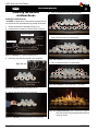
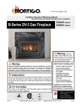
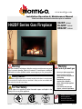
www.montigo.com Installation Operation & Maintenance Manual Check local codes and read all instructions prior to installation. H42DF Indoor HL42DF Indoor HR42DF Indoor H42DF Series Gas Fireplace H42DF Shown Warning: Improper installation, adjustment, alteration, service or maintenance can cause injury or property damage. Refer to this manual. For assistance or additional information consult a qualified installer, service agency or the gas supplier. Safety Notice: Glass doors on gas fireplaces are extremely hot while the fireplace is on and remain hot even after the fireplace has been turned off. Safety screens are available and can reduce the risks of severe burns. For Your Safety: Do not store or use gasoline or other flammable vapors and liquids in the vicinity of this or any other appliance. ® XG0148 C US Canadian Heating Products Inc. Langley, BC V4W 4A Warning: What to do if you smell gas • • Do not try to light any appliance. Do not touch any electrical switch; do not use any phone in your building. • Immediately call your gas supplier from a neighbor's phone. Follow the gas supplier's instructions. • If you cannot reach your gas supplier, call the fire department. • Installer: Leave this manual with the appliance. • Consumer: Leave this manual for future reference. Montigo Del Ray Corp. Ferndale, WA 98248 012810 H42DF Series Indoor Gas Fireplace Warning: Read this manual before installing, operating or troubleshooting this appliance. Please retain this owner's manual for future reference. Congratulations! Congratulations on selecting a Montigo gas fireplace, an elagent and well designed gas fireplace built to your specifications. The Montigo gas fireplace you have selected is designed to provide the utmost in safety, reliability, and engineering standards. As the owner of this new fireplace, you'll want to read and carefully follow all the instructions contained in this Installation, Operations and Maintenance manual. Pay special attention to all cautions, warnings, and Important warnings. This owner's manual should be retained for future reference. We suggest that you keep it with all your other important documents and product manuals. The information contained in this owner's manual, unless noted otherwise, applies to all models, and gas control systems. Your new Montigo gas fireplace will give you years of durable, reliable use. Welcome to the Montigo family of gas fireplace products. Safety Alert Key: • DANGER! Indicates a hazardous situation which, if not avoided will result in death or serious injury. • WARNING! Indicates a hazardous situation which, if not avoided could result in death or serious injury. • CAUTION! Indicates a hazardous situation which, if not avoided, could result in minor or moderate injury. • NOTICE: Used to address practices not related to personal injury. • Important: Used to address practices not related to personal injury. Table Of Contents Congratulations Safety Alert Key Introduction................................................................................ 3 Installing HL42DF Designer Beads............................... 16 Installation Installing H42DF Logset................................................ 17 Installing and Framing the Fireplace............................... 4 Installing the Designer Rocks....................................... 18 Installing the Gasline....................................................... 5 Operation .........................................................................19 - 23 Vent Installation............................................................... 5 Maintenance . ...................................................................23 - 25 Installation Requirements................................... 5 Troubleshooting............................................................. 24 Installing the Remote Switch.............................. 5 Vent Terminations............................................... 6 Warranty .................................................................................. 25 Installing the Standoffs....................................... 6 Appendix Spare Parts................................................................... 24 Top Vent Runs.......................................................... 9 - 11 A. Termination Locations............................................... 26 Power Vent Runs...................................................12 - 13 B State of Massachusetts / Amendment...................... 27 Finishing around the fireplace Fireplace Facing............................................... 14 Mantels and Surrounds.................................... 14 Wiring . .................................................................14 - 15 Removing and Installing the Door..........................15 - 16 Page 2 Part No. XG0148 - 012810 H42DF Series Indoor Gas Fireplace Introduction Thank You for choosing a Montigo Gas Fireplace. About this Fireplace: The H42DF-Series is an line of fireplace's with a standard LogSet, also Linear-style burner, or Stainless steel, and Premium model. These fireplaces can be converted to both a Top Vent or Rear Vent application, and are available in the specific models below. The H42DF is rated for Natural Gas and Liquid Propane at 34,000 Max. BTU/H (9.97) Kilowatts, 25.000 Min. BTU/H Input. ► H42DF; Top or Rear Vent convertible, Millivolt Pilot ► H42DF-I; Top or Rear Vent convertible, Intermittent Pilot (HSI) The HL42DF is rated for Natural Gas and Liquid Propane at 32,000 Max. BTU/H (9.97) Kilowatts, 21,000 Min. BTU/H Input. ► HL42DF-F; Top or Rear Vent convertible, (Electronic HSI IPI). The HR42DF is rated for Natural Gas and Liquid Propane at 34,000 Max. BTU/H (9.97) Kilowatts, 25.000 Min. BTU/H Input. ► HR42DF; Top or Rear Vent convertible, Millivolt Pilot ► HR42DF-F; Top or Rear Vent convertible, (Electronic HSI IPI). This manual covers installation, operation and maintenance. Lighting, operation and care of this fireplace can be easily performed by the homeowner. However, all installation and service work should be performed by a qualified or licensed installer, plumber, or gas fitter who is qualified or licensed by the state, province, region, or governing body in which the appliance is being installed. This manual covers all models and unless otherwise specified, the designation H42DF refers to all variations of the model above. Sections which are specific to a particular variation are marked with a symbol, plus the appropriate model number. Warranty and Installation Information: The Montigo warranty will be voided by, and Montigo disclaims any responsibility for, the following actions: ► Modification of the fireplace and/or components including Direct-Vent assembly or glass doors. ► Use of any component part not manufactured or approved by Montigo in combination with this Montigo fireplace system. ► Installation other than as instructed in this manual. Consult your local Gas Inspection Branch on installation requirements for factory-built gas fireplaces. Installation & repairs should be done by a qualified contractor. Installations in Canada must conform to the current CAN/CGA B-149.1 and .2 Gas Installation Code and local regulations. If the optional aircirculating fan kit is installed, it must be electrically grounded in accordance with CSA C22.1 Canadian Electrical Code Part 1 and/or Local Codes. Installations in the USA must conform to local codes, or in the absence of local codes to the National Fuel Gas Code, ANSI Z223.1-1988. If the optional air-circulating fan is installed, it must be grounded in accordance with local codes or, in the absence of local codes, with the National Electrical Code, ANSI/NFPA 70-1987. See Appendix for installation within the State of Massachusetts. This fireplace must comply with NFPA-54 Chapter 10. CAUTION! Due to its high operating temperatures, the appliance should be located out of traffic & away from furniture and draperies. Children and adults should be alerted to the hazards of the high surface temperature, which could cause burns or clothing ignition. Young children should be carefully supervised when they are in the same room as the appliance. Clothing or other flammable materials should not be placed on or near the appliance. Part No. XG0148 - 012810 WARNING! When this appliance is installed directly on carpeting, tile or any combustible material other than wood flooring, it must be installed on a metal or wood panel extending the full width and depth of the appliance. Page 3 H42DF Series Indoor Gas Fireplace Installation Installing The Fireplace Shell Framing The fireplace may be installed in any location that maintains proper clearances to air conditioning ducts, electrical wiring and plumbing. Safety, as well as efficiency of operation, must be considered when selecting the fireplace location. Try to select a location that does not interfere with room traffic, has adequate ventilation, and offers an accessible pathway for Direct Vent installation. Refer to page 4 - Vent Installation for more information. The fireplace dimensions for H42-DF models are shown below: K J I CCLL M” N” Figure 2. Framing dimensions. H J Q” C B K J Figure 3. Minimum Corner framing dimensions, using a 45° elbow. B H42DF HL42DF HR42DF 5 1/4” A Side View Front View Figure 1. Fireplace dimensions. E F 283/4 1 283/4 1 283/4 1 1 37 G 20 20 20 17 1/4 M N 46 463/8 463/8 42 42 42 L F D 1 1/4 1 1/4 1 1/4 1 1/4 H 28 28 28 217/8 I 121/2 121/2 121/2 10 J 5 5 5 4 K 8 8 8 7 L 33 33 33 40 O 215/8 P 68 Q 48 1/8 215/8 215/8 68 68 481/8 481/8 R N/A N/A N/A T S 40 1/8 40 1/8 40 1/8 45 45 45 / When installing a shelf over the top of the fireplace, the following guidelines must be adhered to: For Rear Vent applications the minimum clearance from the top of the fireplace to a shelf is 9". For Top Vent applications, the minimum clearance is 17 1/2". (Minimum 2" clearance must still be maintained around the vent pipes.) Header Shelf These clearances apply to all dimensions except the framed opening, where the clearance to combustibles is 0". The H42-DF Series clearances to combustible materials are: H42DF 9" 171/2 " 1" 1" 0" 4" HL42DF 9" 171/2" 1" 1" 0" 4" HR42DF 9" 171/2" 1" 1" 0" 4" * Clearances from the top of the fireplace to a combustible ceiling within the fireplace enclosure. 3/8 / Clearances Top - Rear Vent * Top - Top Vent Back Sides Floor Mantle** N” P” G D D C 391/2 391/2 391/2 313/8 0" clearance to corners only G 6 1/4” A B H42DF 42 401/2 HL42DF 42 401/2 HR42DF 42 401/2 34 48 O” K Top View D * When sheetrock is not used behind the fireplace, framing depth may be reduced by 5/8" N.G. & L.P. 33” N.G. & L.P. Top Vent 9” Cieling M S MIN 1” Rear Vent (N.G. & L.P.) MEL Short Header MIN 84” to 96” 7” Rear Vent Alcove area over Fireplace Header 3” 12” Shelf ** Refer to page 14. door opening N.G. & L.P. N.G. & L.P. 17 1/2” Floor Unprotected combustible walls which are perpendicular to the fireplace opening, must not project beyond the shaded area shown in Figure 25. For protection against freezing temperatures, it is recommended that outer walls of the chase be insulated with a vapor barrier. This will reduce the possibility of a cold-air convection current on the fireplace. Page 4 45” M Top Vent or Rear Vent (with alcove) Top Vent (N.G. & L.P.) Figure 4. Framing for shelves over the fireplace. Part No. XG0148 - 012810 H42DF Series Indoor Gas Fireplace Installation Installing The Gas Line Vent Installation The gas line must be installed before finishing the H42DF-Series Fireplace. Natural Gas requires a minimum inlet gas supply pressure of 5.5" W.C. & a manifold pressure of 3.5" W.C. Propane Gas requires a minimum inlet gas supply pressure of 11" W.C. & a manifold pressure of 10" W.C. Provision must also be made for a 1/8" N.P.T. plugged tapping and be accessible for test gauge connection immediately upstream of the gas supply controls to the appliance. The fireplace gas connection and the main operating gas valve is located behind the removable trim at the bottom of the unit and need only be attached to the gas line with an approved fitting, as required by the applicable installation codes. This section covers the installation of direct venting and terminations. To access the fireplace gas connection the main burner must be removed as shown below in figure 5b. All joints must be secured with a minimum of two screws per joint • Only use gas shut-off valves approved for use by the state, province, region, or governing body, in which the appliance is being installed, or as required by the applicable installation codes. Horizontal runs must be supported by a minimum of two supports per horizontal • Flexible gas connectors must not exceed 3 feet in length, unless it is allowable within applicable installation codes. Installation Requirements H42DF-Series fireplaces are certified for use with Montigo Standard Series (5" / 8") venting components. Minimum clearance to combustible construction around the vent pipe is 1" on all sides, except on horizontal venting where the top of the pipe must have a clearance of at least 2". Use only certified Montigo vent components. (Use of other parts will void the Montigo warranty, and may impede the operation of the fireplace.) Vent terminations must not be recessed in walls or siding run. A minimum of one screw on each side of support is also required Flex vent sections may be stretched up to 50% of their total length (eg. a 24" section may be stretched to 36") Solid vent sections may be cut less than half way from the female end Gasline Acces 0.875 dia. Venting components can be used in any combination of solid/rigid pipe or flex pipe and in any orientation (Male connectors can face in any direction) Vent Terminations 2 7 to center Figure 5a. Gas line access. Selecting A Termination Location Choosing your vent termination location will help to determine whether you need to use a top vent or rear vent fireplace. Figure 6a, below, shows typical fireplace locations and the venting options they provide. For a more detailed diagram of allowed termination locations, see Appendix A. Burner Tray Gasket Figure 5b. Gas line access. The appliance and its individual shut-off valve must be disconnected from the gas supply piping system during any pressure testing of that system at test pressures in excess of 1/2 psig (3.5 kPa). The appliance must be isolated from the gas supply piping system by closing its individual manual shut-off valve during any pressure testing of the gas supply piping system at test pressures equal to or less than 1/2 psig (3.5 kPa). Note: After gas line is connected, each appliance connection, valve and valve train must be checked while under normal operating pressure with either a liquid solution, or leak detection device, to locate any source of leak. Tighten any areas where bubbling appears or leak is detected until bubbling stops completely or leak is no longer detected. DO NOT use a flame of any kind to test for leaks. Part No. XG0148 - 012810 Figure 6a. Fireplace locations and vent terminations. Cautions: Vent terminations can be very hot. If the termination is less than 7 feet above a public walkway, it should be fitted with a certified Montigo Heat Guard. (Part no. PTKOG). Do not obstruct, or attempt to conceal the vent termination. These actions will affect the operation of the fireplace, and may be hazardous. In heavy snow areas, take extra care to prevent snow buildup from obstructing the vent termination. Use Montigo Vinyl Heat Shield (Part no. VSS) when using on applications with vinyl siding to guard against possible damage. Page 5 H42DF Series Indoor Gas Fireplace Installation Installing Terminations with Built-In Frames Installing Heat Guards over Terminations 11 PTO (5"/8") PTO-4F (5"/8") 11 MTKOG (4"/7") PTKOG (5"/8") Figure 4d. Installing a PTO termination heat guard. Figure 4a. Installing a PTO termination. 1. Frame the termination opening to 11" x 11". 2. Fasten the termination to the studs using a minimum of 4 screws. 1. Ensure that the two long mounting brackets are facing the bottom of the termination. (See inset). This will provide more heat protection at the top of the termination, where temperatures are highest. Installing Terminations with MSR Frames 2. Attach to the faceplate of the termination using four sheet metal screws. 12 MSR Installing The Standoffs PTO-3F (5"/8") 12 To avoid elevated mantel temperatures, all H42DF Series gas fireplaces are required to have the supplied standoffs installed. The fireplace is supplied with two standoffs. Bend and install these standoffs on top of the fireplace ensuring that the height of the standoff maintains a 6" clearance. Figure 4b. Installing a PTO termination with the MSR frame. 1. Frame the termination opening to 12" x 12". 2. Fasten the termination to the studs using a minimum of 4 screws. Figure 6b. Installing the standoff's. Installing Terminations with MOSR Frames steel lintel is in place, (Part No. L42087) (see Figure 2), the supplied nailing extension must be placed along the top edge of the fireplace and securely fastened in place to the metal lintel, and combustible wood framing. Note: The nailing flange extension can be substituted with a piece of NON-Combustible material of the same size and thermal characteristics, ie: cement board or equivilent. MOSR 12 12 PTO-3F (5"/8") Figure 4c. Installing a PTO termination with the MOSR frame. 1. Frame the termination opening to 12" x 12". 2. Fasten the MOSR frame to the interior side of the studs using a minimum of 4 screws. 3. Insert the termination into the MOSR frame as shown here, and attach by screwing through the four pilot holes in the termination. Page 6 Figure 6c. Installing the Nailing Flange Extension. Part No. XG0148 - 012810 H42DF Series Indoor Gas Fireplace Installation Converting to Top Vent/ Rear Vent H42DF Top Vent Use the following instructions to convert an H42DF for Top Vent use: 1.Install the 5" inner flue cap on the rear flue outlet and secure the cap in place with five screws, as shown in figure 7a. 2.Install the flue gasket material and flue cover plate on the rear vent outlet . Fasten the plate with four screws, as illustrated below. H42DF Rear Vent Use the following instructions to convert an H42DF for Top Vent use: 1.Install the " inner flue cap on the top flue outlet and secure the cap in place with five screws, as shown in figure 8a. 2.Install the 8" outer flue cap on the top flue outlet, and secure it with five screws, as shown in figure 8a. 8" 7” Outer Flue Cap 4” Inner Flue Cap 5" 7” Outer Flue Cap 8" 4” Inner Flue Cap 5" Figure 7a. Flue cap installation for Top Vented fireplace. 3.Install the 5" inner flue collar and the 8" outer flue collar in place on the top vent outlet using 5 screws, as illustrated below. 4” Inner Flue Collar 5" 8" 7” Outer Flue Collar 4” Inner Flue Cap 5" 7” Outer Flue Cap 8" Figure 7b. Flue collar installation for Top Vented fireplace. Figure 8a. Flue cap installation for Rear Vented fireplace. 3. Install the flue gasket material and flue cover plate on the top vent outlet. Fasten the plate with four screws as illustrated in Figure 8b. 4. Install the 5" inner flue collar and the 8" outer flue collar in place on the rear vent outlet using five screws as illustrated below. 8" 7” Outer Flue Cap 4” Inner Flue Cap 5" 7” Outer Flue Collar 8" 4” Inner Flue Collar 5" Figure 8b. Flue collar installation for Rear Vented fireplace. Part No. XG0148 - 012810 Page 7 H42DF Series Indoor Gas Fireplace Installation Top Vent Venting Runs Available Top Vent Components The following venting components are available for the H42DF-Series Top Vent: For the H42DF Top Vent, there are two types of installations: A) ThroughThe-Wall Installations and B) Vertical (Through-The-Roof) Installations. 5" / 8" Venting A) Through-The-Wall Installations Before you install any venting, you must determine whether the venting run will be acceptable. Unacceptable venting can affect the fireplace's combustion. The Venting Graph Measure the vertical height from the fireplace hearth to the centre of the termination and the horizontal run from the fireplace flue collar to the wall flange of the termination. Plot on the Venting Graph (Fig. 9a) with an 'X'. If the 'X' falls on or above the top boundary of the shaded area, the installation is acceptable. H42DF, HL42DF, HR42DF Example A: (Acceptable Installation) If the vertical dimension from the hearth is 84" and the horizontal run to the wall flange of the vent termination is 36", this would be an acceptable installation. Example B: (Acceptable Installation) If the vertical dimension from the hearth is 72" and the horizontal run to the wall flange of the vent termination is 66", this would be an acceptable installation. Example C: (Unacceptable Installation) Vertical Run (in.) If the vertical dimension from the floor of the fireplace is 74" and the horizontal run to the wall flange of the vent termination is 108", this would not be an acceptable installation. A B A - TerminationP TO-3(3"Length) PTO-3F(3"Length) B - Stucco Kits MSR (Stucco Frame) MOSR(StuccoCan) BSR ( Brick Can) C - Flex Sections PFL-1(12"Section) PFL-2(24"Section) PFL-3(36"Section) PFL-4(48"Section) D - Rigid Sections PEXT-1(12"m/fSection) PEXT-2(24"m/fSection) PEXT-3(36"m/fSection) PEXT-4(48"m/fSection) E - Elbows PEL-90MM (m/m 90° Elbow) PEL-90FF (f/f 90° Elbow) PEL-90FM (f/m 90° Elbow) NOTES: All dimension lengths for vertical or horizontal runs are measured from centre of the vent pipe. Venting runs must fall within the limits set by the venting graph (see Figure 7). Example 1: For our shortest venting configuration use components A and E (see Figure 10). Important: An inspection of the explosion relief flappers and door must be made prior to lighting the fireplace. This will ensure the door gasketing material will provide an adequate seal during operation. C 45” 42” Power Vent models, EDVPV47 LDVPV47, EDVRSPV47, and EDVWSPV47 to be used within the shaded area of graph. (See BELOW for applicable Product information). Figure 9b. Top Vent Venting Graph, (All models) Page 8 Part No. XG0148 - 012810 H42DF Series Indoor Gas Fireplace Installation RHS8 Heat Shield RHS8 Heat Shield PEL PEL-90F/F Elbow Figure 10. Typical Top Vent installation. If the 90° elbow is installed directly on the fireplace, for height to the center of the termination see chart on page 3. Figure 12. Extended Installation using a combination of solid and flex venting. Use the vent graph to determine your allowable run, then select appropriate components. Horizontal Venting 90° Elbow RHS8 Heat Shield Termination PEXT Section RHS8 Heat Sheild Figure 11. Typical Top Vent installation. The solid sections can be used in various combinations to obtain the desired vent run. The vent run must fall within the limits set by the venting graph. Example 2: Figure 13. Retracted Installation using a combination of solid and flex venting. Use the vent graph to determine your allowable run, then select appropriate components. 42” Max. RHS8 Heat Shield Rigid sections and an elbow used in conjunction with 3 ft. flex section (PFL-3) will, when extended in a five foot chase, allow for a maximum horizontal run of twelve and one-half feet from the centre of the fireplace to outside wall and a minimum of 7'6" when retracted in opposite direction (see Figure 12 and 13). "C" flex sections and "D" rigid sections may be used in conjunction with one another to obtain different possible horizontal length installations. NOTE: Flex section with no vertical rise must not exceed maximum horizontal length of 3 feet (see Figure 14). Flex runs over 3 feet must fall within the limits set by the venting graph, and must have a minimum vertical rise of 3" per foot of flex. Part No. XG0148 - 012810 45” Min. Figure 14. Horizontal flex installation with no vertical rise. Page 9 H42DF Series Indoor Gas Fireplace Installation B. Vertical (Through-The-Roof) Installations Vertical rise >12' can be reduced (on applicable models). Vertical Terminations must be installed: • minimum 2' (two feet) above the highest point where vent passes through the roof. • minimum 6' (six feet) from a mechanical air inlet • minimum 18" (1 1/2 feet) from a parapet wall. Maximum vent height is: 35' feet above fireplace. Note: Flame characteristics will change if the maximum vent height is used. Minimum clearances 1" from vent to all combustible materials must be maintained. MEXT/PEXT PEXT PXT-10 A maximum of two offsets (each offset has two 90° bends) may be made and shall not exceed total length of 25% of the vertical vent height, when measured center to center of piping. Example: Typical vent installation. 20' vertical vent 2 - 2' offsets required 25% of 20' = 5' max. offset allowed This venting configuration meets requirements. A- Termination PVTK-1 B - Flex Sections PFL-1(12"Section) PFL-2(24"Section) PFL-3(36"Section) PFL-4(48"Section) C - Rigid Sections PEXT-1(12"m/fSection) PEXT-2(24"m/fSection) PEXT-3(36"m/fSection) PEXT-4(48"m/fSection) D - Support Ring &Plate PSPXT-8 E - Firestop PS-8 F - Roof Flashing PRF-7 (1/12 - 7/12 pt.) PRF-7 (7/12 - 12/12 pt.) G - Adaptor / Vent Reducer PVA5487(5"/8"to4"/7") Figure 15. Straight, vertical venting showing required MXT-10/PXT-10 adaptor (supplied with the MVKT-1/PVTK-1 termination). Figure 16. Vertical venting with 1 offset (1 offset= two 90° bends). Important: HL42DF & HR42DF 5"/8" to be used with VertIcal Vent Run Only. 4"/7" Venting Only allowed if the Vertical venting Run is Power Vented Page 10 Part No. XG0148 - 012810 H42DF Series Indoor Gas Fireplace Installation Reduced Vertical Installation (Power vent Only) It is possible to reduce vertical vent runs from 5"/8" venting to 4"/7" venting. Reduced vertical venting may only be used when the installation exceeds 12 feet and terminates through the roof, and if the vertical vent reducer is used with the following venting configuration. Figure 18. Reducing Vertical Vent from 5/8" to 4/7". (Power-Vent Only) Figure 17. Vertical venting with 2 offsets (1 offset= two 90° bends). 1 MIN 1 MIN. Both sides Typical RHS8 Heat Shield The H42DF-Series of gas fireplaces can also use Power Vents; if the vent run is beyond the scope of this document, or the specifications recommend vent augmentation. There are four 4/7 Power Vent models available. These Power Vents are required for Superior venting, safe operation & years of trouble free operation. The available Montigo Power Vent models are: 1 MIN LDVPV47 (Linear, Interior In-line Power Vent, document, XG0700). Figure 18a. RHS8 Installation. (Install by sliding over vent pipe where it passes through the combustible construction. RHS101 Heat Shield, Outer Section. Power Vents for H42DF, HR42DF, HL42DF Drywall RHS101 Heat Shield, Inner Section. Vent from fireplace EDVPV47 (External Power Vent Module, document, XG0750). EDVRSPV47 (Exterior Vertical Roof mount 4/7 stainless steel Power Vent system, document, XG1303) EDVWSPV47 (Exterior Horizontal Wall mount 4/7 stainless steel Power Vent system, document, XG1302). Termination Framing Figure 18b. RHS101 Installation. (Install by sliding over vent pipe where it passes through the combustible construction. Part No. XG0148 - 012810 Page 11 H42DF Series Indoor Gas Fireplace Installation Rear Vent Venting Runs The H42DF-Series Rear Vent has three possible installations which do not require vertical lift, all of these installations require that you install the RHS101 heat shield. 2. 45° Corner Installation. Attach an EEL-45/PEL-45 (45° elbow) directly onto the flue collar. Cut the EXT-18/PXT-20 to suit, and attach it to the EEL-45/PEL-45. Slide the fireplace into position and attach to the termination. Heat Shield The heat shield (RHS101) must be used on all installations straight through the wall, at the point where the vent pipe connects to the termination. With the heat shield, proper vent clearances can be maintained. The heat shield is not included with the fireplace. PXT-18 PEL-45 Elbow To install the heat shield, slide one section over the vent pipe on the inside of the wall opening, with the circular portion inside the wall cavity. Screw the shield in place over the wall opening. Install the second section on the outside of the wall opening sliding the circular portion into the wall opening. Refer to Figure 19. HSI101 Heat Shield Outer Section Termination PEL-90 Elbow Drywall / Sheetrock HSI101 Heat Shield Inner Section Vent Pipe Figure 20. Corner installation. Framing 3. Corner Installation — 45° or less. 18” Max. Use an PTO-3 termination and an PFL-1 or PFL-2/PFL-2 (12" or 24" compressed length) and a frame, if appropriate. Flex may be turned to obtain desired degree of angle required but must not exceed 45°. Figure 19. Heat Shield. Install by sliding over the vent pipe where it passes through combustible construction. 1. Straight Installation. The height from the hearth to the center of the termination is 33". For straight installations use a 18" extension pipe (PXT-18) with female/ female connections. For shorter installations, cut the PXT-18 to the desired length. Refer to figure 19a. Ensure that the RHS101 heat shield is installed before attaching the pipe to the termination. Note: For Rear Vent models, maximum horizontal run with no vertical lift must never exceed 18". PXT-18 Figure 21. Flex installation. Note: Through the wall venting kits are also available for both the Straight and the Corner Installation. The Kit includes a heat sheild, a PFL-18 (f/f) flexible pipe, and a termination with or without a mounting frame. Figure 19. Extended installation. Page 12 Part No. XG0148 - 012810 H42DF Series Indoor Gas Fireplace Installation B. Multi-Elbow Installations For more difficult installation situations, the H42DF-Series Rear Vent may be installed with two - 90° elbows and up to 15' of horizontal run. If using this installation option, you must adhere to the following guidelines: A - TerminationP TO-3(3"Length) PTO-3F(3"Length) B - Stucco Kits MSR (Stucco Frame) BSR-4(4"BrickFrame) BSR-6(6"BrickFrame) MOSR(StuccoCan) C - Flex Sections PFL-1(12"Section) PFL-2(24"Section) PFL-3(36"Section) PFL-4(48"Section) D - Rigid Sections PEXT-1(12"m/fSection) PXT-20(20"section) PEXT-2(24"m/fSection) PEXT-3(36"m/fSection) PEXT-4(48"m/fSection) E - Elbows PEL-90MM (m/m 90° Elbow) PEL-90FF (f/f 90° Elbow) PEL-90FM (f/m 90° Elbow) PEL-45FM (f/m 45° Elbow) the first 90° elbow must be placed directly on the flue collar you must have a minimum vertical lift of 45" (measured from the hearth) your vent run must fall within the limits set by Figure 22a Before you install any venting, you must determine whether the venting run will be acceptable. Unacceptable venting can affect the fireplace's combustion. The Venting Graph Measure the vertical height from the fireplace hearth to the centre of the termination and the horizontal run from the fireplace flue collar to the wall flange of the termination. Plot on the Venting Graph (Fig. 22a) with an 'X'. If the 'X' falls on or above the top boundary of the shaded area, the installation is acceptable. Example A: (Acceptable Installation) If the vertical dimension from the hearth is 84" and the horizontal run to the wall flange of the vent termination is 36", this would be an acceptable installation. NOTES: All dimension lengths for vertical or horizontal runs are measured from center of the vent pipe. Venting runs must fall within the limits set by the venting graph (see Figure 22a). Example B: (Acceptable Installation) If the vertical dimension from the hearth is 72" and the horizontal run to the wall flange of the vent termination is 66", this would be an acceptable installation. Example C: (Unacceptable Installation) Vertical Run (in.) If the vertical dimension from the floor of the fireplace is 72" and the horizontal run to the wall flange of the vent termination is 84", this would not be an acceptable installation. A B 33” 18” 50” 18" 33” Figure 23. Multi-elbow installation. For H42DF distance 'H' must be a minimum of 50". The vent run must comply with figure 22b. C Power Vent models, EDVPV47 LDVPV47, EDVRSPV47, and EDVWSPV47 to be used within the shaded area of graph. (See BELOW for applicable Product information). Figure 22c. H42DF Multi-Elbow Venting Graph. Part No. XG0148 - 012810 Page 13 H42DF Series Indoor Gas Fireplace Installation Finishing Around the Fireplace Combustible mantels and mouldings may be safely installed over the top and on the front of the fireplace provided that they do not project beyond shaded area shown in Figure 24. Side wall clearances are 3". Combustible surrounds may be installed with 3" clearance to the side of the fireplace as shown in Figure 25. Painting: Special care is recommended by the Master Painters and Decorators Association, when painting the fireplace surrounds, to select and apply a quality Alkyd sealer prior to the applying of latex paints. This is to prevent leaching of water from evaporation and causing a brownish staining effect to paint over coats. Fireplace Facing Drywall/ Sheetrock When selecting the finish material for your fireplace, it is important to remember the following: If the surround of the fireplace is to be painted to match the room decor, heat-resistant paint must be provided . Also, decorative facing must not extend past the fireplace opening at all, because it will interfere with the access to retainers for removal of glass door and access to the lower compartment. Header Facing Material Figure 25. Combustible surrounds. Wiring Horizontal Run (in) Gas Control and Pilot Wiring Figure 24. Combustible mantles and facings. Honeywell (Q3450) Pilot Assembly Mantels & Surrounds NOTE: National Canadian Gas Association mantel test requirements are for fire hazard prevention to combustible materials. Pilot Electrical Harness Connector New technology, to meet consumer and government demands for the wise use of energy, has prompted us to manufacture many models of fireplaces which are hot, fuel and energy efficient. Please be aware; temperatures over the mantel will rise above normal room temperature and walls above fireplace may be hot to touch. Honeywell Gas Control (SV9501M) Gas Control Connector Warning: When covering the upper metal portion of the fireplace with a noncombustible material Please Note: The decorative facing materials may be subject to temperatures in excess of 250° F. This should be considered when selecting facing materials. We recommend careful consideration be given to the effects of elevated mantel temperatures which may be in excess of product design, for example: candles, plastic or pictures. This can cause melting, deformation, discoloration or premature failure of T.V. and radio components. Page 14 H42DF-I Fan Plug Receptacle Junction Box Black White Green 115VAC 24VAC Gnd Screw 40 VA Transformer Wall Switch Figure. 26. Wiring for the H42DF-I with Honeywell gas control and pilot. Part No. XG0148 - 012810 H42DF Series Indoor Gas Fireplace Installation Wiring for the optional Fan Kit All H42DF-Series fireplaces may be equipped with optional fan kits for circulating heat into the living space. Installations in Canada which employ the fans must be electrically grounded in accordance with CSA C22.1 Canadian Electrical Code Part 1 and/or Local Codes. Installations in the USA which employ the fans must be grounded in accordance with local codes or, in the absence of local codes, with the National Electrical Code, ANSI/NFPA 70-1987. For more information see the Fan Kit Installation Guide included with the fan kit. NOTE: If any of the original wire supplied with the appliance is replaced, it must be replaced with the same type, or its equivalent. 5/1/60 Supply G L1 L2 L2-WH G L1-BLK Removing and Installing the Door Removing the door: The H42DF-Series door is removed in a few simple steps. Follow these Steps below to remove the Horizontal access panel, unlatch the door buckles and, remove the door. Replace in reverse order. Step 1: Remove the Horizontal Access Panel: Remove the Horizontal cover by placing fingers in both finger holes, then pushng away from you and lifting out. Place it Finger Holes aside during maintenance or cleaning. Installed Gas Install in reverse order. Valve Cover Figure 28. Removing and installing the the Horizontal Acess Panel Step 2: Locate the Door Buckles: Quick Connect plug to motor Figure. 27. Wiring for optional fans. Figure 28a. Loccate the door buckles. (Both Sides Typical) Step 3: Release the Door Buckles Hand-hold Door Latch Slot Door Latch Hook Figure 28b. Door buckle Tool Step 4: Firmly grasp hand-hold end of Door buckle tool and place the machined end in the slot under door frame. (as shown) 1 Figure 28c. Part No. XG0148 - 012810 Page 15 H42DF Series Indoor Gas Fireplace Installation WARNING! Step 5: Do not attempt to clean glass when hot. Ensure the tool is firmly in the lower end of the slot, (as shown), Then pull toward you (Caution: hold the tool securely). L42DF-ST Do not clean glass with abrasive materials as any glass etching may cause premature glass failure. 2 Do not operate this fireplace without the glass door, or with a broken glass door. Figure 28d. Step 6: Pull hard if necessary to release the spring tension. (Caution: The latch springs back with force, hold the tool securely). 3 Figure 28e. Step 7: Remove the tool from the latch slot. Ensure the latches are hanging freely, the hook end is released from the bottom of the door. (Repeat all 4-steps for the remaining latches). 4 Figure 28f. Step 8: Removing the Door: Grasp the Door on either side, usually midway and lift upward, lift the door carefully up and away from the front of the fireplace. See figures 28g. Place the Door aside in a safe place while maintenance and / or cleaning is being performed. Figure 28g. Removing and installing the glass doors. (Both Sides Typical) Installing the Door: To install the door, hook the top edge of the door frame into place. Lower the door into position and follow the previous steps shown in reverse order. Page 16 Part No. XG0148 - 012810 H42DF Series Indoor Gas Fireplace Installation H42DF Installing the H42DF Log Set Installing the Logs: The H42DF is supplied with a seven ceramic fibre log logset. Unpack the logs and handle them very carefully. the underside of the logs, as shown above, figure 30c insets. Step 5.Place the Centre Front log , Figure 30d below, as shown using the notch cast in the Bottom Rear log as shown in figure 30c above. Step 1.Remove the glass door as described on Page 15. Rear / Bottom Log Pilot Assembly Notch in Log Center Front Log Centerline of Fireplace Fireplace Base Figure 30d. Placing Centre Front Log. Figure 30a. Placing Bottom Rear Log. Step 7.Place the Right Centre log as shown in figure 30e. Step 2.Place the bottom Rear log as shown in figure 30a. Align Right Front Log Groove in Log Align Air Inlets Rest Log Bottom Right Log Bottom Left Log Fireplace Base Figure 30e. Placing Right Center Log. Figure 30b. Placing Bottom Right / Left Logs. Step 3.Place the bottom Right and Left logs as shown in figure 30b. Step 8.Place the Right Center log as shown using the notch in the Top Right log as a guide, figure 30f. Top Right Log Top Left Log Align Pins Place Embers in this area Align Pins Figure 30f. Placing Embers. Top Left Log Notch in Log Top Right Log Figure 30c. Top Left / Right Log. Step 4.Place the Top Right log as shown in figure 30c. using the (4) four alignment pins protruding from the top of the Right and Left Bottom Logs, as shown in figure 30c. With these pins align the Top Right and Left logs using the predetermined alignment holes cast into Part No. XG0148 - 012810 Step 9.Place the Embers as shown in figure 30f. Arrange the ember chips on top of the burner tray. Care should be taken when placing the embers, as blocked burner ports may cause an incorrect flame pattern, carbon deposits and delayed ignition. Also, the embers must never be placed in a way that obstructs any of the air inlet ports, located at the rear of the burner, as shown in figure 30b. Cautions: If logs are not placed properly, excessive sooting will result. The surface of the logs will crack due to the heat from the flames. This is a normal occurrence. Page 17 H42DF Series Indoor Gas Fireplace Installation HR42DF Installing the HR42DF Artificial Rocks 5. Place (18) eighteen faux rocks "D" as shown below. Installing the Artificial Rocks: The HR42DF is supplied with (37) thirty-seven faux ceramic fibre river rock. Unpack the rocks and handle them very carefully. Shown Below: 1. Remove the glass door as described on Pages 15-16. 2. Install Rear faux "A" ceramic 3 in1 Rock as shown in Figure 31. Back of Fireplace 3 in 1 faux Rock "A" Figure 31c. Placement 18-faux ceramic rock "D", (as shown). 6. Place (3) three faux rocks "E" as shown below. Pilot and cover Air Inlets Rock riser Burner holes Figure 31. Placement 3 in 1 rear faux ceramic rock "A". 3. Place the (4) four center faux rocks "B" on the riser spikes. Figure 31D. Placement 3-faux ceramic rock "E", (as shown). 6. Place 11) eleven faux rocks "F" as shown below. Figure 31a. Inset Spikes, 2-per rock 4-Center faux Rock "B" (flat side down) Figure 31E. Placement 11-faux ceramic rock "F", (as shown). Figure 31b. Placement 4-center faux ceramic rock "B". 4. Place (1) one center faux rocks "C" on Pilot cover. Figure 31F. Completed Placement. Note: You may have to adjust the Faux rocks to produce a pleasing flame pattern and reduce sooting. (as shown) Figure 31c. Placement 1-faux ceramic rock "C", (on Pilot cover). Page 18 Part No. XG0148 - 012810 H42DF Series Indoor Gas Fireplace Installation HL42DF Installing the HL42DF Glass Beads and Optional River Rocks Beads The HL42DF fireplace is supplied with Designer Glass beads. Remove the Door and trim as shown in the previous Instruction. Follow these instructions to ensure all parts are removed or replaced as required. Once the Trim and glass doors are removed place the marbles randomly across the pan and the burners as described in Figure 32 to 32d. Note: (N.G.) Natural Gas models, Only cover the Optional burner covers with one layer of designer beads. Figure 32d. Operating Natural gas fireplace with one layer of designer glass beads. Propane HL42DF fireplace have the option of installing the optional cultured rocks or designer glass beads. As described below (Propane gas), the designer beads or cultured rocks cannot cover the burners. Doing so produces an undesireable / uneven flame pattern, and eventual sooting. www.montigo.com Note: (LP gas) Ensure the optional river rocks or designer glass beads do not cover the Burners. Figure 32. Installation of the Optional burner covers , (end to end; place evenly). Figure 33. Completed glass bead installation. (Note: place glass beads on top of mesh pilot cover. Figure 32a. Installation of the designer beads. (Ensure one layer of beads covers the burner and pilot covers. Figure 33a. Operating Propane gas fireplace with designer glass beads surrounding burner tray. Figure 32b. Spreading designer beads evenly . Optional River Rocks The HL42DF fireplace has the option of installing the cultured rocks which mimic real stone. These may be spaced at random, or in a visual pattern of your preference. See the Montigo web site for photographs and ideas. www.montigo.com Figure 32c. Completed glass bead installation. Part No. XG0148 - 012810 Page 19 H42DF Series Indoor Gas Fireplace Operation - Model H42DF H42DF with Continuous Pilot For Your Safety - READ BEFORE LIGHTING: WARNING: If you do not follow these instructions exactly, a fire or explosion may result causing property damage, personal injury or loss of life. A. This appliance has a pilot which must be lighted by hand. When lighting the pilot, follow these instructions exactly. B. BEFORE LIGHTING smell all around the appliance area for gas. Be sure to smell next to the floor because some gas is heavier than air and will settle on the floor. What To Do If You Smell Gas: QQ Do not try to light any appliance. QQ Do not touch any electrical switch; do not use any phone in your building. QQ Immediately call your gas supplier from a neighbour's phone. Follow the gas supplier's instructions. QQ If you cannot reach your gas supplier, call the Fire Department. C. Use only your hand to push in or turn the gas control knob. Never use tools. If the knob will not push in or turn by hand, don't try to repair it, call a qualified service technician. Force or attempt to repair may result in a fire or explosion. D. Do not use this appliance if any part has been under water. Immediately call a qualified service technician to inspect the appliance and to replace any part of the control system, and any gas control which has been under water. Lighting Instructions: 1. 2. 3. 4. STOP! Read the safety information above on this label. Lift out the lower Horizontal access panel. to "OFF." Push in gas control knob and turn clockwise Wait five (5) minutes to clear out any gas. Smell for gas, including near the floor. If you then smell gas, STOP! Follow "B" in the safety information above on this label. If you don't smell gas, go to the next step. 5. Locate pilot burner (See illustration at right.) and follow steps below. to 6. Turn knob on gas control counter clockwise "PILOT." 7. Push in gas control knob completely and hold. Light with Piezo Igniter button. Continue to hold the control knob in for about (1) minute after the pilot is lit. Release the knob and it will pop back up. Pilot should remain lit. If it goes out repeat steps 3 through 8. QQ If knob does not pop up when released. Stop and immediately call your service technician or gas supplier. QQ If the pilot will not stay lit after several tries, turn the gas control knob to "OFF" and call your service technician or gas supplier. 8. Push in gas control knob and turn to "ON." counter-clockwise 9. Replacethe lower Horizontal access panel. NOTE: Gas control knob cannot be turned from "PILOT" to "OFF" unless knob is pushed in slightly. Do not force. To Turn Off Gas To Appliance: 1. Turn off remote switch. 2. Lift out the lower Horizontal access panel. 3. Push in gas control knob slightly and turn "Off". Do not force. clockwise to 4. Replace the lower Horizontal access panel. Page 20 Part No. XG0148 - 012810 H42DF Series Indoor Gas Fireplace Operation - Model H(R)42DF-I H42DF-I HR42DF-I with Honeywell Electronic Ignition For Your Safety - READ BEFORE LIGHTING: WARNING: If you do not follow these instructions exactly, a fire or explosion may result causing property damage, personal injury or loss of life. A. This appliance is equipped with an ignition system that lights the pilot burner automatically. Do not attempt to light the pilot by hand. B. BEFORE LIGHTING smell all around the appliance area for gas. Be sure to smell next to the floor because some gas is heavier than air and will settle on the floor. What To Do If You Smell Gas: Do not try to light any appliance. Do not touch any electrical switch; do not use any phone in your building. Immediately call your gas supplier from a neighbour's phone. Follow the gas supplier's instructions. If you cannot reach your gas supplier, call the Fire Department. C. Use only your hand to push in or turn the gas control knob. Never use tools. If the knob will not push in or turn by hand, don't try to repair it, call a qualified service technician. Force or attempt to repair may result in a fire or explosion. D. Do not use this appliance if any part has been under water. Immediately call a qualified service technician to inspect the appliance and to replace any part of the control system, and any gas control which has been under water. Lighting Instructions: 1. STOP! Read the safety information above on this label. 2. Flip down the lower trims. 8. If the fireplace does not operate, follow the instructions "To Turn Off Gas To Appliance" and call your service technician or gas supplier. 3. Turn switch on the gas control to OFF". 4. Wait 5 minutes to clear out any gas. If you smell gas, STOP! Follow "B" in the safety information above on this label. If you don't smell gas, go to the next step. 5. Turn switch on the gas control to "ON". NOTE: This unit is equipped with an ignition system that lights the pilot burner automatically. Do not attempt to light the pilot by hand. 6. Turn on wall switch. 7. Flip up the lower trim. Gas Inlet Gas Control Switch Shown in "On" Position To Turn Off Gas To Appliance: 1. Turn off remote switch. 3. Turn the switch on the gas control to "Off". 2. Flip down the lower trim. 4. Flip up the trim. Part No. XG0148 - 012810 Page 21 H42DF Series Indoor Gas Fireplace Operation Page 22 Part No. XG0148 - 012810 H42DF Series Indoor Gas Fireplace Operation - Model HL42DF-F HL42DF-F with Proflame SIT Electronic Ignition with American For Your Safety - Flame READElectronic BEFORE Ignition LIGHTING: WARNING: If you do not follow these instructions exactly, a fire or explosion may result causing property damage, personal injury or loss of life. A. This appliance is equipped with an ignition system that lights the pilot burner automatically. Do not attempt to light the pilot by hand. B. BEFORE LIGHTING smell all around the appliance area for gas. Be sure to smell next to the floor because some gas is heavier than air and will settle on the floor. What To Do If You Smell Gas: Do not try to light any appliance. Do not touch any electrical switch; do not use any phone in your building. Immediately call your gas supplier from a neighbour's phone. Follow the gas supplier's instructions. If you cannot reach your gas supplier, call the Fire Department. C. Use only your hand to push in or turn the gas control knob. Never use tools. If the knob will not push in or turn by hand, don't try to repair it, call a qualified service technician. Force or attempt to repair may result in a fire or explosion. D. Do not use this appliance if any part has been under water. Immediately call a qualified service technician to inspect the appliance and to replace any part of the control system, and any gas control which has been under water. Lighting Instructions: 1. STOP! Read the safety information above on this label. 2. Remove the lower Horizontal access panel. 3. Turn Incoming gas valve to the ON" position. 4. Wait 5 minutes to clear out any gas. If you smell gas, STOP! Follow "B" in the safety information above on this label. If you don't smell gas, go to the next step. 5. Turn wall switch "ON". 6. If the Fireplace does not light, the System will cycle through two trials, (one minute audible clicking, thirty seconds of silence, and then another one minute of audible clicking). If the system locks out due to inadequate gas flow, refer to "Troubleshooting", Page 20. 7. After completion of the information in the Troubleshooting section, Repeat step 5. 8. If the system will not function correctly, follow the instructions "To Turn Off Gas To Appliance" and call your service technician or gas supplier. EV1 (Pilot burner) EV2 (Main burner) Pilot Adjust Screw Pilot Sensor Lockout Reset Key Diagnostic Terminal Igniter Ground EV1 (Pilot burner) EV2 (Main burner) Power Gas "In" Gas "Out" Incoming Gas Line, Shut-off Valve To fireplace Main burner Command (Wall switch) To Turn Off Gas To Appliance: 1. Turn off remote switch. 3. Turn the incoming gas control valve to "Off". 2. Remove the lower Horizontal access panel. 4. Replace the lower Horizontal access panel. Part No. XG0148 - 012810 Page 23 H42DF Series Indoor Gas Fireplace Operation Maintenance Lighting Instructions General Have the fireplace and installation inspected yearly. The inspection must include, but is not limited to, the following: See pages 20 to 23. • A visual check of the entire vent system and termination. • An inspection of the explosion relief flappers and the door gasketing to ensure a proper seal. • An inspection of the burner, venturi, and primary air openings. • An inspection of the gas valve, gas components, and pilot flame. For your convenience a 1/8" manifold pressure tap is supplied on the gas valve for a test gauge connection. See Figure 32. • Ensure proper log placement as per this manual. • Inspection of all optional equipment; fans, thermostats, etc. For Natural Gas this appliance requires a minimum inlet pressure of 5.5" W.C. and a manifold pressure of 3.5" W.C. For Propane Gas this appliance requires a minimum inlet pressure of 11" W.C. and a manifold pressure of 10" W.C. Always keep the fireplace area clear and free of combustible materials, as well as gasoline and other flammable vapors and liquids. Do not use this appliance if any part has been under water. Immediately call a qualified service technician to inspect the appliance and to replace any part of the control system and any gas control which has been under water. Cleaning When the fireplace is first activated, there may be some smoking and a visible film may be left on the glass. This is a normal condition, and is the result of burning of protective coatings on new metal. Glass must be cleaned periodically to remove any film (which is a normal by-product of combustion) which may be visible. Film can easily be removed by removing the door, as shown on page 15. Handle the door carefully, and clean it with non-abrasive glass cleaners. One of the most effective products is Kel Kem. Silicone seals on inner door during initial firing will "off gas", leaving a visual deposit of a white substance on combustion chamber walls. This can easily be removed using normal household products. Use a vacuum cleaner or whisk broom to keep the control compartment, burner, and firebox free from dust and lint. Logs may be cleaned periodically with a vacuum to remove soot or other contaminates. Cautions: WARNING! Do not attempt to clean glass when hot. Fireplace gas control must be in the “OFF” position and pilot and main burners extinguished when cleaning appliance with a vacuum. Doors and logs can get very hot. Handle only when cool. Page 24 L42DF-ST Do not clean glass with abrasive materials as any glass etching may cause premature glass failure. Do not operate this fireplace without the glass door, or with a broken glass door. Part No. XG0148 - 012810 H42DF Series Indoor Gas Fireplace Maintenance Troubleshooting Spare Parts H42DF H42DF HL42DF HR42DF Gas Valve NG RGC1006 RGC3033 RGC1006 Gas Valve LP RGC1005 RGC3034 - Pilot NG RPA020 RPA020 RPA020 Pilot LP RPA021 RPA021 - Burner NG RBH4201 - RBH4201 Burner LP RBH4202 - - ROR1120 - ROR1120 ROR1121 - - Door RDTH42 RDTH42 RDTH42 Log Set RLGSH42 N/A RR42GRAY RLGSH42B N/A N/A Log Base HONEYWELL SV9500 /9600 Troublshooting Sequence NOTE: Before Troubleshooting, Familiarize Yourself With START The Startup And Checkout Procedure. SV9500 / SV9600 is powered (24VAC nominal) NO YES HL42DF-F Follow this information to reset the SIT System: 1. Locate the lead to the battery backup, (remove) YES Turn gas on. Pilot Burner Lights? NO NO SYSTEMOK Replace SV9500/ SV9600 Replace Igniter / Flame Rod Assembly Measure Volume to SV9500 / SV9600 Voltage must be at least 19.5 VAC NO Check Transformer Line Volt Supply Replace Igniter / Flame Rod Assembly 2. Locate the AC/DC wall transformer, (Unplug connector) YES NO YES YES Main Valve opens? Unplug Pilot Burner Cable, Measure Voltage at SV9500/SV9600 HSI Terminals (24VAC Nominal, see INSET) Replace SV9500/SV9600 (Refer to schematic, below) (Refer to schematic, below) HSI - Line voltage power Terminals - Low voltage transformer - Limit Controller - Thermostat - Wiring - Air proving switch on combustion air blower system -Vent damper (if used) is open and end switch made YES Igniter warms up and glows red. Pilot Valve opens. INSET CHECK: - TurnGasSupplyOff - Set thermostat to call for heat NO Troubleshooting H42DF-I NO Replace Igniter / Flame Rod Assembly and retain. Restart troubleshooting Sequence. Does main valve open? YES NO Replace SV9500 / SV9600. Save old Igniter/ Flame Rod Assembly for service. Discard old Igniter / Flame Rod Assembly 1. 2. If your fireplace still does not operate correctly, consult your dealer or the manufacturer. All service and repairs should be performed by a qualified agency. All spare parts, optional fans, and optional trim finishes are available from your local dealer or the manufacturer. If your fireplace still does not operate correctly, consult your dealer or the manufacturer. Part No. XG0148 - 012810 Page 25 H42DF Series Indoor Gas Fireplace Warranty The Warranty The Companies warrants the Montigo Gas Appliance to be free from defects in materials and workmanship at the time of manufacture. On the Montigo, there is a ten-year warranty on the firebox and its components, a five-year warranty on the main burner and pilot burner, and a one-year warranty on the gas control valve and fibre logs. Glass, plated/painted finishes, and refractory lining are exempt. Remedy And Exclusions The coverage of this Warranty is limited to all components of the Gas Appliance manufactured by The Companies. This Warranty only covers Montigo Gas Appliances installed in the United States or Canada. If the components of the Gas Appliance covered by this Warranty are found to be defective within the time frame stated (see The Companies right of investigation outlined below). The Companies will, at its option, replace or repair defective components of the Gas Appliance manufactured by The Companies at no charge, and will also pay for reasonable labour costs incurred in replacing or repairing components. If repair or replacement is not commercially practical, The Companies will, at its option, refund the purchase price of the Montigo Gas Appliance. This Warranty covers only parts and labour as provided above. In no case shall The Companies be responsible for materials, components, or construction which are not manufactured or supplied by The Companies, or for the labour necessary to install, repair or remove such materials, components or construction. All replacement or repair components will be shipped F.O.B. the nearest The Companies factory. Qualifications To The Warranty The Gas Appliance Warranty outlined above is further subject to the following qualifications: (1) The Gas Appliance must be installed in accordance with The Companies installation instructions and local building codes. The Warranty on this Montigo Gas Appliance covers only the component parts manufactured by The Companies. The use of components manufactured by others with this Montigo Gas Appliance could create serious safety hazards, may result in the denial of certification by recognized national safety agencies, and could be in violation of local building codes. This warranty does not cover any damages occurring from the use of any components not manufactured or supplied by The Companies (2) The Montigo Gas Appliance must be subjected to normal use. The Gas Appliances are designed to burn gas only. Burning conventional fireplace fuels such as wood, coal or any other solid fuel will cause damage to the Gas Appliance, will produce excessive temperatures and will result in a fire hazard. Limitations On Liability It is expressly agreed and understood that The Companies sole obligation, and purchaser's exclusive remedy under this Warranty, under any other warranty, expressed or implied, or in contract, tort or otherwise, shall be limited to replacement, repair, or refund, as specified above. In no event shall The Companies be responsible for any incidental or consequential damages caused by defects in its products, whether such damage occurs or is discovered before or after replacement or repair, and whether or not such damage is caused by The Companies negligence. Some states do not allow the exclusion or limitation of incidental or consequential damages, so the above limitation or exclusion may not apply to you. The duration of any implied warranty with respect to this Montigo Gas Appliance is limited to the duration of the foregoing warranty. Some states do not allow limitation on how long an implied warranty lasts, so the above may not apply to you. Investigation Of Claims Against Warranty The Companies reserves the right to investigate any and all claims against this Warranty and to decide upon method of settlement. The Companies Are Not Responsible For Work Done Without Written Consent The Companies shall in no event be responsible for any warranty work done without first obtaining The Companies written consent. Dealers Have No Authority To Alter This Warranty The Companies employees and dealers have no authority to make any warranties nor to authorize any remedies in addition to or inconsistent with those stated above. How To Register A Claim Against Warranty In order for any claim under this Warranty to be valid, The Companies must be notified of the claimed defect in writing or by telephone, as soon as reasonably possible after the defect is discovered. Claims against this Warranty in writing should include the date of installation, and a description of the defect. Other Rights This Warranty gives you specific legal rights, and you may also have other rights which vary from state to state. NOTE: The Companies as stated above refer to - Canadian Heating Products Inc. and/or Montigo Del Ray Corp. Canadian Heating Products Inc. and/or Montigo DelRay Corp. reserves the right to make changes at any time, without notice, in design, materials, specifications, prices and also to discontinue colors, styles and products. Page 26 Part No. XG0148 - 012810 H42DF Series Indoor Gas Fireplace Appendix A - Termination Locations A = clearance to the termination frame above grade, veranda, porch, deck, or balcony [16 inches (41 cm) minimum] N = † clearance above paved sidewalk or a paved driveway located on public property [*7 feet (2.1 m) minimum] B = clearance to door, or sides and top of window, that may be opened [16 inches (41 cm) minimum for appliances ≤100 000 BTU/H (30kW)] P = c l e a r a n c e u n d e r v e r a n d a , p o r c h , d e c k , o r b a l c o n y [16 inches (41 cm) minimum‡ to non-combustibles] [22 inches (56 cm) minimum‡ to combustibles] C = clearance to bottom of window that may be opened horizontally [36 inches (92 cm) minimum for appliances ≤100 000 BTU/H (30kW)] Q = clearance above a roof [24 inches (61 cm) minimum] D = no clearance to permanently closed window when installed with approved glass penetration termination R = clearance to adjacent walls and neighboring buildings [18 inches (46 cm) minimum] E = clearance to permanently closed window [16 inches 41 cm recommended to prevent condensation on window] S = c l e a r a n c e f r o m c o r n e r i n r e c e s s e d l o c a t i o n [12 inches (31 cm) minimum] F = vertical clearance to ventilated soffit located above the termination within a horizontal distance of 2 feet (61 cm) from the centreline of the termination [22 inches (56 cm) minimum] T = m a x i m u m d e p t h i n [48 inches (122 cm) minimum] G = c l e a r a n c e t o u n v e n t i l a t e d s o f f i t [ 1 6 i n c h e s (41 cm) minimum to non-combustibles] [22 inches (56 cm) minimum to combustibles] H = clearance to outside corner [9 inches (23 cm) minimum] I = clearance to inside corner [12 inches (31 cm) minimum] J = * not to be installed above a meter/regulator assembly within 40" (103 cm) horizontally from the centreline of the regulator K = clearance to service regulator vent outlet [3 feet minimum in the United States] [*6 feet (1.8 m) minimum in Canada] recessed location U = m i n i m u m w i d t h f o r b a c k w a l l o f r e c e s s e d l o c a t i o n [24 inches (61 cm) minimum] V = no horizontal clearance between the frames of two terminations that are level. W = horizontal clearance between the frames of two terminations that are not level. [36 inches (92 cm) minimum] † a vent shall not terminate directly above a sidewalk or paved driveway which is located between two single family dwellings and serves both dwellings L = clearance to non-mechanical air supply inlet to building or the combustion air inlet to any other appliance [16 inches (41 cm) minimum for appliances ≤100 000 BTU/H (30kW)] M = clearance to mechanical air supply inlet [*6 feet (1.8 m) minimum] only permitted if veranda, porch, deck, or balcony has an open side that is equal to or greater than the depth of the enclosed area * as specified in CGA B149 Installation Codes. Note: local Codes or Regulations may require different clearance. ‡ Part No. XG0148 - 012810 Page 27 H42DF Series Indoor Gas Fireplace Appendix B - State of Massachusetts Amendment (Gas Fireplace / Equipment sold in the State of Massachusetts) 5.08: Modifications to NFPA-54, Chapter 10 (1) Revise NFPA-54 section 10.5.4.2 by adding a second exception as follows: Existing chimneys shall be permitted to have their use continued when a gas conversion burner is installed, and shall be equipped with a manually reset device that will automatically shut off the gas to the burner in the event of a sustained back-draft. (2) Revise 10.8.3 by adding the following additional requirements: (a) For all side wall horizontally vented gas fueled equipment installed in every dwelling, building or structure used in whole or in part for residential purposes, including those owned or operated by the Commonwealth and where the side wall exhaust vent termination is less than seven (7) feet above finished grade in the area of the venting, including but not limited to decks and porches, the following requirements shall be satisfied: 1. INSTALLATION OF CARBON MONOXIDE DETECTORS. At the time of installation of the side wall horizontal vented gas fueled equipment, the installing plumber or gas fitter shall observe that a hard wired carbon monoxide detector with an alarm and battery back-up is installed on the floor level where the gas equipment is to be installed. In addition, the installing plumber or gas fitter shall observe that a battery operated or hard wired carbon monoxide detector with an alarm is installed on each additional level of the dwelling, building or structure served by the side wall horizontal vented gas fueled equipment. It shall be the responsibility of the property owner to secure the services of qualified licensed professionals for the installation of hard wired carbon monoxide detectors a. In the event that the side wall horizontally vented gas fueled equipment is installed in a crawl space or an attic, the hard wired carbon monoxide detector with alarm and battery back-up may be installed on the next adjacent floor level. b. In the event that the requirements of this subdivision can not be met at the time of completion of installation, the owner shall have a period of thirty (30) days to comply with the above requirements; provided, however, that during said thirty (30) day period, a battery operated carbon monoxide detector with an alarm shall be installed. 2. APPROVED CARBON MONOXIDE DETECTORS. Each carbon monoxide detector as required in accordance with the above provisions shall comply with NFPA 720 and be ANSI/UL 2034 listed and IAS certified. 3. SIGNAGE. A metal or plastic identification plate shall be permanently mounted to the exterior of the building at a minimum height of eight (8) feet above grade directly in line with the exhaust vent terminal for the horizontally vented gas fueled heating appliance or equipment. The sign shall read, in print size no less than one-half (1/2) inch in size, “GAS VENT DIRECTLY BELOW. KEEP CLEAR OF ALL OBSTRUCTIONS”. 4. INSPECTION. The state or local gas inspector of the side wall horizontally vented gas fueled equipment shall not approve the installation unless, upon inspection, the inspector observes carbon monoxide detectors and signage installed in accordance with the provisions of 248 CMR 5.08(2)(a)1 through 4. (b) EXEMPTIONS: The following equipment is exempt from 248 CMR 5.08(2)(a)1 through 4: 1. The equipment listed in Chapter 10 entitled “Equipment Not Required To Be Vented” in the most current edition of NFPA 54 as adopted by the Board; and 2. Product Approved side wall horizontally vented gas fueled equipment installed in a room or structure separate from the dwelling, building or structure used in whole or in part for residential purposes. (c) MANUFACTURER REQUIREMENTS - GAS EQUIPMENT VENTING SYSTEM PROVIDED. When the manufacturer of Product Approved side wall horizontally vented gas equipment provides a venting system design or venting system components with the equipment, the instructions provided by the manufacturer for installation of the equipment and the venting system shall include: 1. Detailed instructions for the installation of the venting system design or the venting system components; and 2. A complete parts list for the venting system design or venting system. (d) MANUFACTURER REQUIREMENTS - GAS EQUIPMENT VENTING SYSTEM NOT PROVIDED. When the manufacturer of a Product Approved side wall horizontally vented gas fueled equipment does not provide the parts for venting the flue gases, but identifies “special venting systems”, the following requirements shall be satisfied by the manufacturer: 1. The referenced “special venting system” instructions shall be included with the appliance or equipment installation instructions; and 2. The “special venting systems” shall be Product Approved by the Board, and the instructions for that system shall include a parts list and detailed installation instructions. (e) A copy of all installation instructions for all Product Approved side wall horizontally vented gas fueled equipment, all venting instructions, all parts lists for venting instructions, and/or all venting design instructions shall remain with the appliance or equipment at the completion of the installation. (3) After NFPA-54 section 10.10.4.2 add a new section 10.10.4.3 as follows: When more than four gas appliances are to be vented through a common gas vent or common horizontal vent manifold, a plan of the proposed vent installation shall be submitted to the Inspector and the serving gas supplier for review and approval. Extraction from: Massachusets Rules and Regulations 5.00: Amendments To 2002 Edition Of ANSI Z223.1-NFPA-54 Page 28 Part No. XG0148 - 012810 H42DF Series Indoor Gas Fireplace Notes: Part No. XG0148 - 012810 Page 29 XG0148 - 012810 Canadian Heating Products Inc. Montigo Del Ray Corp. Langley, BC V4W 4A1 Ferndale, WA 98248