1
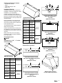
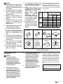
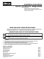
Installation Instructions Epicure and Millennia Range Hoods ® ™ For use with models: EHD30, EHD36, EHD42, EHD48, EHD54 EHDR30, EHDR36, EHDR42, EHDR48, EHDR54 MHD30, MHD36, MHD48 read and save these instructions Tested in accordance with the latest edition of ANSI/UL 507 standard for electric fans and can/csa-c22.2 no. 113 Standard for fans and ventilators. CONVENTIONS USED IN THESE INSTRUCTIONS WARNINGS: Must be followed carefully to avoid personal injury or damage. NOTES: Contain helpful hints and tips to facilitate the installation. IMPORTANT 1. 2. 3. 4. 5. Before beginning installation, please thoroughly read and become familiar with these instructions. Installation and service must be completed by a qualified installer or service agency. Installer: Please leave these installation instructions with the owner. Owner: Please keep these instructions for local electrical inspector’s use and for future reference. Read the accompanying use and care manual prior to operating this appliance. TABLE OF CONTENTS Verifying package contents Installation planning Overall dimensions Cabinet preparation Duct planning Electrical power supply requirements Installing the hood Connecting the electrical power Verifying proper operation Part No. 65211 Rev. D Page Page Page Page Page Page Page Page Page 2 2 2 3 3 4 4 4 4 IMPORTANT SAFETY INSTRUCTIONS WARNINGS: 1. Read all instructions before using the appliance. 2. Install or locate this appliance only in accordance with these installation instructions. 3. Do not operate this appliance if it has a damaged electrical conduit or wires, if it is not working properly or if it has been damaged or dropped. 4. 5. 6. 7. 8. 9. 1 This appliance should be serviced only by qualified service personnel. Locate the nearest Dacor authorized service representative at (800) 793-0093, or at www.Dacor.com for examination, repair or adjustment. If the information in this manual is not followed exactly, a fire or explosion may result causing property damage, personal injury, or death. Do not store or use gasoline or other flammable vapors and liquids in the vicinity of this or any other appliance. Improper installation, adjustment, alteration, service, or maintenance can cause personal injury or property damage. Refer to these instructions and the accompanying use and care manual. For assistance or additional information, consult a qualified installer, service agency, or dealer. Keep appliance area clear and free from combustible material. To reduce the risk of fire, use only approved duct work materials. 10. TO REDUCE THE RISK OF FIRE, ELECTRIC SHOCK, OR INJURY TO PERSONS, OBSERVE THE FOLLOWING: a) Use this unit only in the manner intended by the manufacturer. If you have questions, contact the manufacturer. b) Before servicing or cleaning unit, switch power off at service panel and lock the service disconnecting means to prevent power from being switched on accidentally. When the service disconnecting means cannot be locked, securely fasten a prominent warning device, such as a tag, to the service panel. Exception: The additional safety instructions do not apply to a ceilingsuspended fan. 11. For General Ventilating Use Only. Do Not Use To Exhaust Hazardous Or Explosive Materials And Vapors. WARNING: To reduce the risk of fire and electric shock, when installing EHDR series hoods, DO NOT install more than one in-line or external blower to increase the length of the duct run. Even small differences between blower air flow rates can greatly reduce the air draw by the hood. Install only the in-line or remote blower models specified in these instructions. WARNING: To reduce the risk of fire and electric shock, when installing EHD and MHD series hoods, DO NOT install an in-line or external blower to increase the length of the duct run. Even small differences between blower air flow rates can greatly reduce the air draw by the hood. WARNING: To reduce risk of fire and to properly exhaust air, be sure to duct air outside – Do not vent exhaust air into spaces within walls or ceilings or into attics, crawl spaces or garages. WARNING: TO REDUCE THE RISK OF FIRE, USE ONLY METAL DUCT WORK. WARNING: TO REDUCE THE RISK OF FIRE, ELECTRIC SHOCK, OR INJURY TO PERSONS, OBSERVE THE FOLLOWING: a) Installation work and electrical wiring must be done by qualified person(s) in accordance with all applicable codes and standards, including fire-rated construction. b) Sufficient air is needed for proper combustion and exhausting of gases through the flue (chimney) of fuel burning equipment to prevent back drafting. Follow the heating equipment manufacturer’s guidelines and safety standards such as those published by the National Fire Protection Association (NFPA), and the American Society for Heating, Refrigeration and Air Conditioning Engineers (ASHRAE), and the local code authorities. c) When cutting or drilling into wall or ceiling, do not damage electrical wiring and other hidden utilities. d) Ducted fans must always be vented outdoors. Verifying the Package Contents • • • • CL 11 7/8" (302mm) Use and care manual Filters Light bulbs, halogen 75W Suction cup CL "A" CL 6 ½" 6 ½" (165mm) (165mm) 6 1/8" (156mm) CL Installation Planning A qualified technician must complete the installation of this built-in appliance. Proper installation is your responsibility. Carefully check the location where the hood is to be installed. The hood should be placed for convenient access. Make certain that electrical power can be provided in the selected location. Plan the installation so that all minimum clearances are met or exceeded. Dimensions shown provide minimum clearances, unless otherwise noted. Overall Dimensions (MHD Series Shown) Model No. (A) Width EHD3018 EHDR3018 29 7/8” (759mm) The specified minimum cabinet depth and width must be provided. EHD3618 EHDR3618 35 7/8” (911mm) Cabinet cutout dimensions must be used as indicated. All contact surfaces between the appliance and the cabinet must be solid and level. EHD4218 EHDR4218 41 7/8” (1064mm) EHD4818 EHDR4818 47 7/8” (1216mm) EHD5418 EHDR5418 53 7/8” (1368mm) MHD3018 29 7/8” (759mm) MHD3618 35 7/8” (911mm) MHD4818 47 7/8” (1216mm) Make certain that you have everything necessary to ensure a proper installation before proceeding. Overall Dimensions NOTE: All tolerances + 1/16”, - 0” unless otherwise stated. Vertical Exhaust Duct Location 4209, 4809 Configurations Top View (EHD Series Shown) "B" (B) Depth CL 3 1/4" x 10" (83x254mm) Duct CL 4" (102mm) 26 7/8” (683mm) Horizontal Exhaust Duct Location 3018, 3618 Configurations Rear View (EHD Series Shown) CL 25 1/2” (648mm) 18” High Hood Overall Dimensions 11 7/8" (302mm) 8" (203mm) Round Duct Collars 18 (457mm) CL CL 6" 6" (152mm) (152mm) CL 4" (102mm) 3 1/4" x 10" (83x254mm) Ducts Exhaust Duct Locations "A" CL 9 (229mm) 8" (203mm) Round Duct Collar CL 6 1/8" (156mm) Horizontal Exhaust Duct Location 4218, 4818, 5418 Configurations Rear View (EHD Series Shown) 10" Round Overall Dimensions (MHD Series Shown) Model No. (A) Width EHD3009 EHDR3009 29 7/8” (759mm) EHD3609 EHDR3609 35 7/8” (911mm) EHD4209 EHDR4209 41 7/8” (1064mm) EHD4809 EHDR4809 47 7/8” (1216mm) MHD3009 29 7/8” (759mm) MHD3609 35 7/8” (911mm) MHD4809 47 7/8” (1216mm) "B" (B) Depth Vertical Exhaust Duct Location 3009, 3609, 3018, 3618 Configurations Top View (EHD Series Shown) 12" (305mm) CL 24” (610mm) 10" (254mm) Round Duct Collar CL 6 1/8" (156mm) 21" (533mm) 8" (203mm) 22 1/2” (571mm) Vertical Exhaust Duct Location 4218, 4818, 5418 Configurations Top View (EHD Series Shown) ADT10 Custom Transition For 4209, 4809 Configurations 9” High Hood Overall Dimensions 2 Electrical Access Hole Locations Rear of hood CL CL CL A Model A B C D CL EHD3009 EHDR3009 MHD3009 9” (229mm) 1 ½” (38mm) 9” (229mm) 1 ½” (38mm) 1 1/2" (38mm) EHD3609 EHDR3609 MHD3609 9 ½” (241mm) 2” (51mm) 8” (203mm) 1 ½” (38mm) EHD4209 EHDR4209 14” (356mm) 1 ½” (38mm) 14” (356mm) 1 ½” (38mm) EHD4809 EHDR4809 MHD4809 16 ½”” (419mm) 1 ½” (38mm) 16 ½”” (419mm) 1 ½” (38mm) EHD3018 EHDR3018 MHD3018 9” (229mm) 1 ½” (38mm) 9” (229mm) 1 ½” (38mm) EHD3618 EHDR3618 MHD3618 9 ½” (241mm) 2” (51mm) 8” (203mm) 3 ½” (89mm) EHD4218 EHDR4218 14 7/16” (367mm) 1 ½” (38mm) 14 7/16” (367mm) 1 ½” (38mm) EHD4818 EHDR4818 MHD4818 14 7/16” (367mm) 1 ½” (38mm) 16 15/16” (430mm) 1 ½” (38mm) EHD5418 EHDR5418 14 7/16” (367mm) 4 ½” (114mm) 14 7/16” (367mm) 4 ½” (114mm) B 7/8"ø (11mm) Holes Vertical Electrical Access Hole Locations, Top View D CL CL C CL Top of hood CL 3/4" (19mm) 7/8"ø (11mm) Holes Horizontal Electrical Access Hole Locations, Rear View Cabinet Preparation Duct Planning WARNINGS: WARNING: 1. ailure to provide proper F minimum clearance may result in a fire or safety hazard. NOTES: 1. Minimum hood clearances are zero inches (0”) to the rear, sides and top of the hood. 2. Thirty inches (30”) is the minimum distance between the bottom of the hood and any cooking surface. 3. Maximum effective clearance from cooking surface to bottom of hood is 36” (914mm). 2. "A" 30" (762mm) Minimum from cooktop surface to bottom of hood 3. 4. Cabinet Planning 3 Hood Width A - Cutout Width 30” 30” (762mm) 36” 36” (915mm) 42” 42” (1067mm) 48” 48” (1219mm) 54” 54” (1372mm) CAUTION: To reduce the risk of fire and to properly exhaust air, be sure to duct air outside. Do not vent exhaust air into spaces within walls or ceilings, or into attics, crawl spaces or garages. Tape all duct joints securely to prevent combustion by-products, smoke or odors from entering the home. This will also improve the efficiency of the system. Do not exhaust more than one vent into a single duct run. Only use duct work constructed of materials deemed acceptable by state, municipal and local codes. NOTES: 1. Best performance is achieved by using round duct instead of rectangular, especially when elbows are required. 2. If multiple elbows are needed, ensure that there is a minimum of 24” of straight duct between any two elbows. 3. Avoid “S” or “back to back” configurations caused by adjacent elbows. 4. Thermal breaks, such as a short section of non-metallic duct, should be used in areas of extreme cold. 5. A back-draft damper at the duct outlet may also be required. 11. It is important to keep as few turns in the duct run, and to keep the run as short as possible. 12. EHDR series hoods are not equipped with an internal blower. Installation of an in-line (Dacor model ILB8) or remote blower (Dacor model REMP3) is required. Model Install the in-line or Series remote blower according to the blower installation instructions before EHD installing the hood. MHD 13. If installing an in-line blower, it must be located within 60 equivalent feet of the hood canopy system. 6. Do not use flexible metal duct. 9. The vent hood and cooking appliance(s) must be removable if service is required. 10. Be certain that the duct work does not interfere with floor joists or wall studs. Electrical Power Supply Requirements 2. If the power supply requirements shown do not agree with those listed on the product data plate, provide a power source per the information found on the product data plate. If the electrical service provided does not meet the product specification, or does not conform to the NEC or local standards, do not proceed with the installation. Call a licensed electrician to correct the electrical service before proceeding. Maximum Equivalent Straight Lengths Internal Blower ILB8 REMP3 8” Round 60’ NA NA 10” Round 50’ NA NA 3 1/4” x 10” 50’ NA NA 8” Round NA 60’ 60’ 10” Round NA 50’ 50’ 3 1/4” x 10” NA 50’ 50’ Recommended Maximum Straight Lengths 3 1/4" x 10" 45° Elbow Roof Cap or Wall Cap with Damper 3 1/4" x 10" 90° Flat Elbow 15 Feet 7 Feet 30 Feet 20 Feet Transistion 3 1/4" x 10" to Round 45° Elbow Round Duct 90° Transistion 3 1/4" x 10" to 8" Round 90° Elbow Round Duct 8" Diameter - 4 Feet 10" Diameter - 4 Feet 8" Diameter - 3 Feet 10" Diameter - 2 Feet 25 Feet 8" Diameter - 7 Feet 10" Diameter - 5 Feet Recommended sheet metal elbows, transition, and wall cap equivalent straight lengths 3. NOTES: 1. Duct Size 3 1/4" x 10" 90° Elbow 7. Do not use duct work that is smaller in cross-sectional area than the recommended size duct. 8. Do not rely on duct tape alone to seal duct joints. Use sheet metal screws as require to support the duct weight. EHDR MHDR Refer to the table below for recommended maximum straight lengths of duct to provide adequate performance. Refer to the table above for recommended sheet metal elbows, transitions, and wall cap equivalent straight lengths. 4. It is the owner’s responsibility to ensure that electrical installation of this appliance is performed by a qualified electrician. The electrical installation must comply with the National Electric Code ANSI/NFPA 70-1990 (or to latest revision) and local codes and ordinances. Failure to disconnect electric power may result in electrical shock or fire hazard. The correct voltage, frequency and amperage must be supplied to the appliance from a separate, grounded, circuit that is protected by a properly sized circuit breaker or time delay fuse. Refer to the data plate located on the blower housing, inside the filter area. The specifications below are provided for reference and do not supersede the information on the product data plate. Electrical Supply Requirements 120 Vac, 60 Hz, 15 Amp. Dedicated Circuit Total Connected Load 1.4 kW (12 A) 4 Installing the Hood Connecting the Electrical Power WARNINGS: WARNINGS: A minimum of two people are required to safely lift the hood. 1. 1. Remove the filters from the hood canopy and remove the shields below the power ventilator. 2. The hood comes pre-wired from the factory. Route the supplied cable through the electrical access hole that will be used for the installation location. 3. Mount a 2 X 4 ledger board to support the hood temporarily in the mounting location, 30” (762mm) above the finished countertop. 4. While lifting the hood onto the top of the ledger board, route the wiring harness from the hood to the power supply connection point. 3. Secure the hood through the keyhole slots in the top of the hood and/or the slot hole in the rear of the hood. 4. Remove the temporary support ledger. Top mounting holes (both sides) Rear mounting holes Wiring harness Temporary support ledger. Temporary Support Ledger Installation (9” MHD series hood shown) Top mounting holes (both sides) Rear Wiring mounting holes harness Ensure that the power is disconnected before proceeding. 2. Verify that power supply matches the rating found on the hoods data plate before proceeding. 3. The hood must be properly grounded at all times before power is applied. 4. Do not ground the hood with the neutral (white) house supply wire. A separate wire must be utilized. 5. If aluminum house supply wiring is used, splice the hoods copper wires to the aluminum house wiring with special connectors designed and agency-certified for this purpose. Follow the connector manufacturer’s recommended procedure carefully. Improper connection can result in a fire hazard. 6. Failure to complete electrical connections properly may result in a damaged or a nonfunctional system. Follow the wiring diagrams carefully to ensure a proper installation. Model EHDR series hoods only: 1. Install the remote or in-line blower (see page 4 for specifications) according to the blower installation instructions. 2. Route the wiring from the in-line or remote blower into the hood through one of the electrical access holes in the hood. Connect them to the remote blower (ILB8/REMP3) connection terminal as shown below. Match wire colors. Temporary Support Ledger Installation (18” MHD series hood shown) 5 Connect the pre-wired, white and green wires to the corresponding black, white and ground (green) wire from the power source wiring. Use wire nut connectors to secure the connections. Verifying Proper Operation 1. Install the filters. 2. Install the light bulbs. - Attach the included suction cup to one of the provided light bulbs. - Insert it into one of the light fixtures. - Screw it into place and remove the section cup. - Repeat for the remaining light fixtures. 3. Verify that the hood control knobs are in the OFF position (fully counterclockwise). 4. Turn on the main power supply at the circuit breaker panel or fuse box. 5. Turn the light and fan knobs clockwise and make sure the lights and fans operate properly. If the hood does not operate properly, follow these troubleshooting steps: 1. Verify that power is being supplied to the hood. ILB/REMP wiring terminal inside hood Temporary support ledger. Connect to Hood Wiring GREEN Not used GREEN Gnd WHITE N1 WHITE 2. Check the electrical connections to ensure that the installation has been completed correctly. BLACK L1 BLACK 3. Repeat the above test. Wires from in-line/remote blower Wires connected to hood wiring harness, do not remove 4. If the appliance still does not work, contact an authorized Dacor service company. If you are unable to locate a Dacor Service company, please contact Dacor at (800) 793-0093, or visit us on the web at www.Dacor.com. Do not attempt to repair the appliance yourself. Dacor is not responsible for service required to correct a faulty installation. 6 Web Site: For a Dealer/Service: Corporate Phone: www.Dacor.com (800) 772-7778 (800) 793-0093