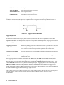
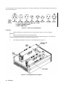
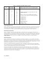
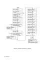
1
Operating Manual Agilent Technologies Electronic Load Mainframes Models 6050A and 6051A For instruments with Serial Numbers: Agilent 6050A-2908A-00101 and Above Agilent 6051A-2927A-00101 and Above Agilent Part No. 5959-3368 Microfiche Part No. 5959-3369 Printed in USA: October, 1997 Reprinted April, 2000 CERTIFICATION Agilent Technologies certifies that this product met its published specifications at time of shipment from the factory. Agilent Technologies further certifies that its calibration measurements are traceable to the United States National Bureau of Standards, to the extent allowed by the Bureau’s calibration facility, and to the calibration facilities of other International Standards Organization members. WARRANTY This Agilent Technologies hardware product is warranted against defects in material and workmanship for a period of three years from date of delivery. Agilent Technologies software and firmware products, which are designated by Agilent Technologies for use with a hardware product and when properly installed on that hardware product, are warranted not to fail to execute their programming instructions due to defects in material and workmanship for a period of 90 days from date of delivery. During the warranty period Agilent Technologies will, at its option, either repair or replace products which prove to be defective. Agilent Technologies does not warrant that the operation of the software, firmware, or hardware shall be uninterrupted or error free. For warranty service, with the exception of warranty options, this product must be returned to a service facility designated by Agilent Technologies Customer shall prepay shipping charges by (and shall pay all duty and taxes) for products returned to Agilent Technologies for warranty service. Except for products returned to Customer from another country, Agilent Technologies shall pay for return of products to Customer. Warranty services outside the country of initial purchase are included in Agilent Technologies product price, only if Customer pays Agilent Technologies international prices (defined as destination local currency price, or U.S. or Geneva Export price). If Agilent Technologies is unable, within a reasonable time to repair or replace any product to condition as warranted, the Customer shall be entitled to a refund of the purchase price upon return of the product to Agilent Technologies LIMITATION OF WARRANTY The foregoing warranty shall not apply to defects resulting from improper or inadequate maintenance by the Customer, Customer-supplied software or interfacing, unauthorized modification or misuse, operation outside of the environmental specifications for the product, or improper site preparation and maintenance. NO OTHER WARRANTY IS EXPRESSED OR IMPLIED. AGILENT TECHNOLOGIES SPECIFICALLY DISCLAIMS THE IMPLIED WARRANTIES OF MERCHANTABILITY AND FITNESS FOR A PARTICULAR PURPOSE. EXCLUSIVE REMEDIES THE REMEDIES PROVIDED HEREIN ARE THE CUSTOMER’S SOLE AND EXCLUSIVE REMEDIES. AGILENT TECHNOLOGIES SHALL NOT BE LIABLE FOR ANY DIRECT, INDIRECT, SPECIAL, INCIDENTAL, OR CONSEQUENTIAL DAMAGES, WHETHER BASED ON CONTRACT, TORT, OR ANY OTHER LEGAL THEORY. ASSISTANCE The above statements apply only to the standard product warranty. Warranty options, extended support contracts, product maintenance agreements and customer assistance agreements are also available. Contact your nearest Agilent Technologies Sales and Service office for further information on Agilent Technologies’ full line of Support Programs. 2 SAFETY SUMMARY The following general safety precautions must be observed during all phases of operation, service, and repair of this instrument. Failure to comply with these precautions or with specific warnings elsewhere in this manual violates safety standards of design, manufacture, and intended use of the instrument. Agilent Technologies assumes no liability for the customer’s failure to comply with these requirements. BEFORE APPLYING POWER. Verify that the product is set to match the available line voltage and the correct fuse is installed. GROUND THE INSTRUMENT. This product is a Safety Class 1 instrument (provided with a protective earth terminal). To minimize shock hazard, the instrument chassis and cabinet must be connected to an electrical ground. The instrument must be connected to the ac power supply mains through a threeconductor power cable, with the third wire firmly connected to an electrical ground (safety ground) at the power outlet. For instruments designed to be hard-wired to the ac power lines (supply mains), connect the protective earth terminal to a protective conductor before any other connection is made. Any interruption of the protective (grounding) conductor or disconnection of the protective earth terminal will cause a potential shock hazard that could result in personal injury. If the instrument is to be energized via an external autotransformer for voltage reduction, be certain that the autotransformer common terminal is connected to the neutral (earthed pole) of the ac power lines (supply mains). FUSES. Only fuses with the required rated current, voltage, and specified type (normal blow, time delay, etc.) should be used. Do not use repaired fuses or short circuited fuseholders. To do so could cause a shock or fire hazard. DO NOT OPERATE IN AN EXPLOSIVE ATMOSPHERE. Do not operate the instrument in the presence of flammable gases or fumes. KEEP AWAY FROM LIVE CIRCUITS. Operating personnel must not remove instrument covers. Component replacement and internal adjustments must be made by qualified service personnel. Do not replace components with power cable connected. Under certain conditions, dangerous voltages may exist even with the power cable removed. To avoid injuries, always disconnect power, discharge circuits and remove external voltage sources before touching components. DO NOT SERVICE OR ADJUST ALONE. Do not attempt internal service or adjustment unless another person, capable of rendering first aid and resuscitation, is present. DO NOT EXCEED INPUT RATINGS. This instrument may be equipped with a line filter to reduce electromagnetic interference and must be connected to a properly grounded receptacle to minimize electric shock hazard. Operation at line voltages or frequencies in excess of those stated on the data plate may cause leakage currents in excess of 5.0 mA peak. SAFETY SYMBOLS. Instruction manual symbol: the product will be marked with this symbol when it is necessary for the user to refer to the instruction manual (refer to Table of Contents) . Indicates hazardous voltages. Indicate earth (ground) terminal. The WARNING sign denotes a hazard. It calls attention to a procedure, practice, or the like, which, if not correctly performed or adhered to, could result in personal injury. Do not proceed beyond a WARNING sign until the indicated conditions are fully understood and met. The CAUTION sign denotes a hazard. It calls attention to an operating procedure, or the like, which, if not correctly performed or adhered to, could result in damage to or destruction of part or all of the product. Do not proceed beyond a CAUTION sign until the indicated conditions are fully understood and met. DO NOT SUBSTITUTE PARTS OR MODIFY INSTRUMENT. Because of the danger of introducing additional hazards, do not install substitute parts or perform any unauthorized modification to the instrument. Return the instrument to an Agilent Technologies Sales and Service Office for service and repair to ensure that safety features are maintained. Instruments which appear damaged or defective should be made inoperative and secured against unintended operation until they can be repaired by qualified service personnel. 3 SAFETY SUMMARY (continued) GENERAL Any LEDs used in this product are Class 1 LEDs as per IEC 825-l. ENVIRONMENTAL CONDITIONS This instruments is intended for indoor use in an installation category II, pollution degree 2 environment. It is designed to operate at a maximum relative humidity of 95% and at altitudes of up to 2000 meters. Refer to the specifications tables for the ac mains voltage requirements and ambient operating temperature range. SAFETY SYMBOL DEFINITIONS Symbol Description Alternating current Description Terminal for Line conductor on permanently installed equipment Caution, risk of electric shock Both direct and alternating current Caution, hot surface Three-phase alternating current Caution (refer to accompanying documents) Earth (ground) terminal In position of a bi-stable push control Protective earth (ground) terminal Out position of a bi-stable push control Frame or chassis terminal On (supply) Terminal for Neutral conductor on permanently installed equipment Terminal is at earth potential(Used for measurement and control circuits designed to be operated with one terminal at earth potential.) Off (supply) Direct current Symbol Standby (supply) Units with this symbol are not completely disconnected from ac mains when this switch is off. To completely disconnect the unit from ac mains, either disconnect the power cord or have a qualified electrician install an external switch. Herstellerbescheinigung Diese Information steht im Zusammenhang mit den Anforderungen der Maschinenläminformationsverordnung vom 18 Januar 1991. * Schalldruckpegel Lp <70 dB(A) * Am Arbeitsplatz * Normaler Betrieb * Nach EN 27779 (Typprufung). Manufacturer’s Declaration This statement is provided to comply with the requirements of the German Sound Emission Directive, from 18 January 1991. * Sound Pressure Lp <70 dB(A) *At Operator Position * Normal Operation * According to EN 27779 (Type Test). 4 DECLARATION OF CONFORMITY according to ISO/IEC Guide 22 and EN 45014 Manufacturer’s Name: Agilent Technologies, Inc. Manufacturer’s Address: New Jersey Division 150 Green Pond Road Rockaway, NJ 07866 U.S.A. declares that the product Product Name: Load mainframe and modules Model Number(s): Agilent 6050A, 6051A mainframes with modules Agilent 60501A/B, 60502A/B, 60503A/B, 60504A/B, 60507A/B conform(s) to the following Product Specifications: Safety: EMC: 1 IEC 348:1978 / HD401 S1:1981 CISPR 11:1990 / EN 55011:1991 IEC 801-2:1991 / EN 50082-1:1992 IEC 801-3:1984 / EN 50082-1:1992 IEC 801-4:1988 / EN 50082-1:1992 Group 1, Class B 4kV CD, 8 kV AD 3 V/m 0.5 kV Sig. Lines, 1 kV Power Lines Supplementary Information: The product herewith complies with the requirements of the Low Voltage Directive 73/23/EEC and the EMC Directive 89/336/EEC and carries the CE-marking accordingly. Note 1: The product family was introduced prior to 12/93 New Jersey, January 1997 -------------------------------------------------------Bruce Krueger / Quality Manager European Contact: Your local Agilent Technologies Sales and Service Office or Agilent Technologies GmbH, Department TRE, Herrenberger Strasse 130, D-71034 Boeblingen (FAX:+49-7031-14-3143) Printing History The current edition of this guide is indicated below. Reprints of this guide containing minor corrections and updates may have the same printing date. New editions are identified by a new printing date and, in some cases, by a new part number. A new edition incorporates all new or corrected material since the previous edition. Changes to the guide occurring between editions are covered by change sheets shipped with the guide. Also, if the serial number prefix of your power module is higher than those listed on the title page of this guide, then it may or may not include a change sheet. That is because even though the higher serial prefix indicates a design change, that change may not affect the content of the guide. Edition 3 ..................... Update ......... May, 1993 October, 1997 April, 2000 Copyright 1993 Agilent Technologies, Inc. This document contains proprietary information protected by copyright. All rights are reserved. No part of this document may be photocopied, reproduced, or translated into another language without the prior consent of Agilent Technologies The information contained in this document is subject to change without notice. 5 If you are a first-time user, start with this manual, paying particular attention to Chapter 2. After installation (Chapter 3), read Chapter 4 to learn front-panel operation. Programming users should then read Chapter 5 before going to the Programming Reference Guide. Experienced programming users will probably refer only to the Programming Reference Guide. Agilent 6050A/6051A Operating Manual Agilent Part No. 5959-3368 (this manual) Specifications System Overview Installation Procedures Front-Panel Operation Remote Programming Introduction Calibration Procedures Module-Specific Pages Agilent Models 60501A/B, 60502A/B, 60503A/B, 60504A/B, 60507B Specifications Programming Ranges Factory Default Settings Calibration Information Agilent Technologies Electronic Load Family Programming Reference Guide Agilent Part No. 06060-90005 Introduction to HPSL Introduction to Programming Language Dictionary Status Reporting Agilent 6050A/605L4 Service Manual Module Service Manuals * Supplied with Agilent 6050A/6051A Electronic Load Mainframe. ** Supplied with individual load modules. *** Available for purchase. Supplied with instrument if ordered as Option 910. 6 Table of Contents 1. General Information What’s in this Manual ................................................................................................................................11 Options ..................................................................................................................... ..................................11 Safety Requirements...................................................................................................................................12 Specifications .............................................................................................................................................12 2. Operation Overview Introduction ................................................................................................................................................15 Front Panel Description..............................................................................................................................16 Remote Programming.................................................................................................................................16 Local/Remote Control ................................................................................................................................16 Extended Power Operation.........................................................................................................................17 Programmable Features ..............................................................................................................................17 Modes of Operation.................................................................................................................................17 Constant Current CC (Mode) ..................................................................................................................18 Ranges .....................................................................................................................................................18 Immediate Current Level.........................................................................................................................18 Triggered Current Level ..........................................................................................................................18 Transient Current Level...........................................................................................................................19 Software Current Limit............................................................................................................................19 Slew Rate.................................................................................................................................................19 Constant Resistance (CR) Mode..............................................................................................................19 Ranges .....................................................................................................................................................20 Immediate Resistance Level....................................................................................................................20 Triggered Resistance Level .....................................................................................................................20 Transient Resistance Level......................................................................................................................20 Slew Rate.................................................................................................................................................20 Constant Voltage (CV) Mode..................................................................................................................20 Range.......................................................................................................................................................20 Immediate Voltage Level ........................................................................................................................21 Triggered Voltage Level .........................................................................................................................21 Transient Voltage Level ..........................................................................................................................21 Slew Rate.................................................................................................................................................21 Transient Operation .................................................................................................................................21 Continuous Transient Operation..............................................................................................................22 Pulsed Transient Operation .....................................................................................................................22 Toggled Transient Operation...................................................................................................................23 Triggered Operation ................................................................................................................................24 Slew Rate and Minimum Transition Time...............................................................................................25 Input Current, Voltage, and Power Measurement ...................................................................................26 Short On/Off............................................................................................................................................26 Input On/off.............................................................................................................................................27 Saving and Recalling Settings .................................................................................................................27 Reading Remote Programming Errors.....................................................................................................27 Status Reporting ......................................................................................................................................28 Protection Features .....................................................................................................................................28 Resetting Latched Protection...................................................................................................................28 Overvoltage .............................................................................................................................................29 7 Table of Contents (continued) Overcurrent..............................................................................................................................................29 Overpower...............................................................................................................................................29 Overtemperature......................................................................................................................................30 Reverse Voltage ......................................................................................................................................30 Control Connector ......................................................................................................................................30 Remote Sensing.......................................................................................................................................30 Monitor Outputs ......................................................................................................................................30 External Programming Input ...................................................................................................................31 Fault.........................................................................................................................................................31 Port On/Off..............................................................................................................................................31 3. Installation Introduction ................................................................................................................................................33 Inspection ...................................................................................................................................................33 Installing The Modules...............................................................................................................................33 Procedure ................................................................................................................................................34 Channel Number......................................................................................................................................35 Installing The Mainframes..........................................................................................................................35 Cooling ....................................................................................................................................................36 Rack Mounting ........................................................................................................................................36 Turn-On Checkout......................................................................................................................................36 Changing Line Voltage............................................................................................................................37 Turn-On/Selftest......................................................................................................................................38 Power Test...............................................................................................................................................39 Controller Connection ................................................................................................................................39 GPIB Address..........................................................................................................................................40 Rear Panel Connectors and Switches .........................................................................................................40 Input Binding Posts .................................................................................................................................40 Control Connector ...................................................................................................................................41 Sense Switch............................................................................................................................................41 Trigger Connector ...................................................................................................................................43 Application Connections ............................................................................................................................43 Wiring Considerations.............................................................................................................................43 Local Sense Connections.........................................................................................................................44 Remote Sense Connections .....................................................................................................................44 Parallel Connections................................................................................................................................44 Zero-Volt Loading Connections ..............................................................................................................45 4. Local Operation Introduction ................................................................................................................................................49 Local Control Overview .............................................................................................................................52 Using The CHAN Keys..............................................................................................................................53 Selecting the Channel ..............................................................................................................................54 Identifying the Selected Channel.............................................................................................................54 Using The Function Keys ...........................................................................................................................54 Turning the Input On/Off ........................................................................................................................54 Setting the Mode of Operation ................................................................................................................56 Setting CC Values ...................................................................................................................................56 Programming Ranges ..............................................................................................................................56 8 Table of Contents (continued) Examples .................................................................................................................................................56 Setting CR Values ...................................................................................................................................57 Programming Ranges ..............................................................................................................................57 Examples ............... .................................................................................................................................58 Setting CV Values ...................................................................................................................................59 Programming Range................................................................................................................................59 Examples .................................................................................................................................................59 Transient Operation .................................................................................................................................60 Shorting the Input ....................................................................................................................................61 Resetting Latched Protection...................................................................................................................61 Using The System Keys..............................................................................................................................62 Setting the GPIB Address........................................................................................................................62 Displaying Error Codes ...........................................................................................................................62 Saving and Recalling Settings .................................................................................................................62 Changing "Wake-up" Settings.................................................................................................................63 Recalling the Factory Default Values......................................................................................................63 5. Remote Operation Introduction ................................................................................................................................................65 Enter/Output Statements.............................................................................................................................65 GPIB Address...............................................................................................................................................65 Sending A Remote Command ....................................................................................................................66 Selecting A Channel ...................................................................................................................................66 Getting Data Back ......................................................................................................................................66 Remote Programming Commands..............................................................................................................67 CC Mode Example ..................................................................................................................................68 CV Mode Example ..................................................................................................................................68 CR Mode Example ..................................................................................................................................71 Continuous Transient Operation Example...............................................................................................71 Pulsed Transient Operation Example ......................................................................................................72 Synchronous Toggled Transient Operation Example ..............................................................................72 6. Calibration Introduction ................................................................................................................................................75 Equipment Required...................................................................................................................................75 Calibration Commands ...............................................................................................................................76 Calibration Flowcharts ...............................................................................................................................77 Example Programs .....................................................................................................................................77 A. Considerations for Operating in Constant Resistance Mode .......................................................91 Index .............................................................................................................................................................93 Agilent Sales and Support Offices..............................................................................................................97 9 1 General Information What’s In This Manual This manual applies to both the Agilent 6050A and Agilent 6051A Electronic Load mainframes. The two mainframes are functionally identical, but the Agilent 6051A is a half-rack width unit, with only two slots for load modules. Most of the information given in this manual applies to both mainframes. Where differences occur, information specific just to the Agilent 6051A is given in parentheses following information that applies only to the Agilent 6050A, for example: ... a total of 1800 (600) watts... This chapter contains specifications that apply to the Agilent 6050A and Agilent 6051A Electronic Load mainframes, as well as information concerning options and safety requirements. The remaining chapters in this manual contain instructions for installing, operating, programming, and calibrating the Electronic Load as follows Chapter 2 "Operation Overview": describes all of the Electronic Load’s functions and briefly describes how they can be controlled locally at the front panel and/or remotely via a GPIB controller. Chapter 3 "Installation": provides instructions for installing load modules in the mainframe, controller and application connections, and turn-on checkout procedures. Chapter 4 "Local Operation": describes in detail how to operate the Electronic Load at the front panel. Chapter 5 "Remote Operation": provides an introduction to remote programming. Chapter 6 "Calibration": contains calibration procedures for the Electronic Load and gives sample calibration programs. Yearly calibration intervals are recommended. Specifications and other information pertinent to a specific load module are given in the module-specific pages provided with each load module. Options Unless one of the following line voltage options is ordered, the unit is shipped from the factory set for 120 Vac, 48-63 Hz ac input power. If Option 100, 220, or 240 is ordered, the unit will be factory set for the appropriate line voltage. For information about changing the line voltage setting, see "Turn-On Checkout" in Chapter 3. 100: Input Power, 100 Vac, 48-63 Hz 220: Input Power, 220 Vac, 48-63 Hz 240: Input Power, 240 Vac, 48-63 Hz Additional options are: 800: 908: 909: 910: One rack mount kit for two half-rack units side by side (Agilent 6051A only)* One rack mount kit* One rack mount kit with handles (Agilent 6050A only)* One service manual with extra Operating Manual and Programming Reference Guide *Support rails are required for Options 800, 908, and 909. General Information 11 Safety Requirements This product is a Safety Class 1 instrument, which means that it is provided with a protective earth ground terminal. This terminal must be connected to an ac source that has a 3-wire ground receptacle. Review the instrument rear panel and this manual for safety markings and instructions before operating the instrument. Refer to the Safety Summary page at the beginning of this manual for a summary of general safety information. Specific safety information is located at appropriate places in this manual. The Electronic Load is designed to comply with the following safety and environmental requirements: • • • IEC 348-Safety requirements for electronic measuring apparatus. CSA 22.2 No. 231-Electronic instruments and scientific apparatus for special use and applications. UL 1244-Electrical and electronic measuring and testing equipment. Specifications Table 1-1 lists the specifications and supplemental characteristics for the Agilent 6050A/6051A Electronic Load mainframe. All specifications apply over an operating range of 0 to +55°C for the mainframe. Specifications are guaranteed through the warranty of the product. Supplemental characteristics are type-tested or typical values based on a product sample and, while representative, are not guaranteed for all instruments. Table 1-1. Agilent 6050A/6051A Specifications and Supplemental Characteristics Specifications: AC Input: Three internal switches permit operation from 100, 120, 220, or 240 Vac lines. Amplitude: -13% to +6% nominal line voltage Frequency: 48 to 63 Hz Supplemental Characteristics: AC Input: Fuse: The ac input is protected by internal fuses. Maximum VA: 635 GPIB Programming Command Processing Time (Time required for a GPIB command processed by the Electronic Load): 70 milliseconds (typical) GPIB Interface Capabilities: SH1, AH1, T6, L4, SR1, RLI, DT1, DC1 Trigger Input: Vlo = 0.9 V maximum at Ilo = -1 mA Vhi = 3.15 V minimum (pull-up resistor on input) Trigger Input: Vlo = 0.72 V maximum at Ilo = 1 mA Vhi = 4.4 V minimum at Ilo = -20 µA 12 General Information Table 1-1. Agilent 6050A/6051A Specifications and Supplemental Characteristics (continued) Weight: Net (mainframe only): Agilent 6050A, 9.5 kg (21 lb.) Agilent 6051A, 5.5 kg (12 lb.) Shipping: Agilent 6050A, 14 kg (31 lb.) Agilent 6051A, 7.5 kg (17 lb.) Dimensions: Width: Height: Depth: Agilent 6050A, 425.5 mm (16.75 in.) Agilent 6051A, 213 mm (8.4 in.) 178 mm (7 in.), add 10 mm (0.4 in.) for removable feet 625 mm (24.6 in.), including input connectors on modules General Information 13 2 Operation Overview Introduction The Agilent 6050A and Agilent 6051A Multiple Input Electronic Load Mainframes are used for design, manufacturing, and evaluation of dc power supplies, batteries, and power components. Other applications include use as a power circuit breaker or crowbar, high-current function or pulse generator, fuel-cell and photovoltaic cell test, and de-energizing superconducting magnets. The mainframe contains six (two) slots for load modules. Load modules occupy either 1 or 2 slots, depending on the power rating of the module. The mainframe can dissipate up to 300 watts per slot, to a total of 1800 (600) watts for a fully loaded mainframe. An individual module may have either 1 or 2 channels, each of which has its own channel number. Each module contains its own input connectors. The mainframe contains a processor, GPIB connector and interface circuits, trigger circuits, front-panel keypad and display, and other circuits common to all the load modules. Each module can operate independently in constant current (CC) mode, constant voltage (CV) mode , or constant resistance (CR) mode. In addition, each input can be turned on or off (open circuit) or short circuited. Features include built-in GPIB interface and built-in pulse generator, both standard. Pulse mode allows dynamic testing of power supplies and components, without giving the device under test time to heat up. The flexible pulse mode provides six triggering methods, allowing synchronization with a wide variety of events. A Save/Recall feature allows you to save up to 7 complete instrument setups, one of which can be saved in non-volatile memory so that it is recalled automatically at poweron. Also standard is GPIB readback of actual input voltage and current, and extensive protection and status reporting capability. The mainframe contains two (one) cooling fans whose speed automatically increases or decreases as the module temperatures rise and fall. This feature reduces overall noise level because the fans do not run at maximum speed at all times. The input power rating curve for each module is shown in the module-specific pages. See the extended power paragraphs in this section for a description of the power rating curves. Note that regardless of a module’s power rating, input current is derated linearly from 2 volts down to 0 volts. Each load module can be individually controlled either via GPIB or locally via the front panel. Once a channel is selected or addressed, all subsequent commands go to that channel until another channel is selected or addressed. Operation of all models is similar, regardless of power ratings. Therefore, the operating instructions given in this manual are generic, and apply to all modules. The module-specific pages provided with each module include specifications and other information pertinent just to a particular model. Some examples described here may use values that are not appropriate for your module, but the example is valid. Some descriptions refer to ranges, limits, full-scale values, and similar terms (for example, low range and high range). Refer to the module-specific pages provided with each module for the actual values. Programs written for the Agilent 6060 series of single Electronic Loads can be used with the multiple loads, easing program development for applications using various members of the Agilent Electronic Load family. (Triggering via the ac line frequency or the load’s internal timer is available only in the multiple load mainframe.) If your application requires a greater power or current capacity than one module can provide, load modules can be connected in parallel in CC or CR mode. Operation Overview 15 Front Panel Description The front panel includes a 12-character alphanumeric display, 11 status indicators, and four groups of keypads. Ordinarily the alphanumeric display shows the number of the channel presently under front-panel control, and the input voltage and current of that channel. By using the key you can sequentially display input power, programming error codes, and protection-circuit status. If any protection circuits are active, that status will be displayed first when you use the key. If you change channels via the front panel, any fault information will be displayed first for the new channel. Then you can key through the display in the normal sequence. The alphanumeric display also shows what function is being performed when you use the keypads. The display also includes 11 annunciators that point to the 11 status labels printed on the front panel. The Constant Current, Constant Resistance, Constant Voltage, Transient, and Unregulated status annunciators are specific to the channel displayed. The Protection, Error, Shift, Remote, Address, and Service ReQuest status annunciators are channel independent. Four of the keys perform two functions, with the alternative function labeled in blue above the key. The alternative function is selected by first pressing the blue (shift) key, which turns on the Shift annunciator and enables the alternative function. Note that the front-panel display operates independently from the GPIB CHANNEL command. In other words, you can select a channel locally (front panel) for which the display will show the input voltage and current, and the controller can subsequently send commands to other channels without changing the channel being displayed. Remote Programming Commands sent to the Electronic Load via GPIB are decoded by the mainframe microprocessor, which detects syntax and range errors. The mainframe processor also prescales data sent to the modules, and maintains status registers for each module. Three commands have aliases for compatibility with other HPSL instruments. MODE can also be called FUNCtion, INPut can also be called OUTPut, and CHANnel can also be called INSTrument. OUTPut and INSTrument would typically be used if you want your program to refer to the load modules in terms of the device or instrument under test. Be careful if using INSTrument for CHANnel in systems that have more than one Electronic Load mainframe; someone looking at the listing in the future may be misled. Local/Remote Control Local (front panel) control is in effect immediately after power is applied. The front panel keypad and display allow manual control of each individual module when the Electronic Load is used in bench test applications. Remote (computer) control goes into effect (front panel Rmt annunciator is on) as soon as the mainframe receives a command via the GPIB. A built-in GPIB interface and HPSL compatible commands allow control and readback of all functions when the Electronic Load is used in computer controlled applications. With remote control in effect, only the computer can control the Electronic Load; the front panel keypad has no effect. You can, however, still use the front panel display to view the input voltage and current readings. You can return the Electronic Load to local control from remote control by pressing . This will return the Electronic Load to local control, unless the local-lockout command has been received from the GPIB computer. Most of the functions that can be performed remotely over the GPIB can also be performed locally at the front panel. The names on the keys reflect the HPSL commands that are used to program the various functions. Consequently, learning to operate the Electronic Load from the front panel will aid you when you start to write computer programs. Details of local operation are covered in Chapter 4 - Local Operation and fundamentals of remote programming are given in Chapter 5 - Remote Operation. Complete HPSL programming details are given in the Agilent Electronic Loads Programming Reference Guide. The remaining paragraphs in this chapter describe the operating modes, transient 16 Operation Overview operation, protection features, and other operating features of the Electronic Load. Extended Power Operation Note: Extended power operation is not available on "B " load modules (Agilent Models 60501B-60507B). In addition, this feature may not be present in "A" modules produced after 1989. The extended power feature allows a module to dissipate considerably more than its nominal power rating in many cases. The primary factor limiting the amount of power that can be dissipated is the temperature of the current-control pass transistors, as sensed at the heatsink. A module’s nominal power rating is specified for continuous power at high ambient temperature, but in many applications average power is less than 100%, and ambient temperature is considerably lower than the highest specified full-power temperature. In these less-than-extreme applications, each load module can safely dissipate as much as one third more power than its nominal power rating for a limited time. In effect, each module has two power-limit curves, as shown in Figure 2-1. Whether the module is operating with the nominal power-limit curve or the extended power-limit curve is determined by heatsink temperature. The module turns on with extended power available and extended power continues to be available unless and until the internal temperature rises beyond a safe operating point for extended power. At the point, the module automatically reduces the power-limit curve to the module’s nominal power rating, and sets the Extended Power Unavailable (EPU) bit in the status registers. Extended power is available any time the EPU bit (bit 9) is not set. A graph provided in the module-specific specifications under DC Input Rating shows the typical time that a module can operate at full extended power after having stabilized at a given average power before extended power becomes unavailable. Figure 2-1. Power Limit Curves Programmable Features Modes of Operation The three modes of operation are: • constant current (CC) • constant voltage (CV) • constant resistance (CR) Operation Overview 17 When programmed to a mode, a module remains in that mode until the mode is changed or until a fault condition, such as an overpower or overtemperature, occurs. When changing modes, the module’s input is momentarily disabled (non-conducting state) before the new mode is enabled. This insures that there will be minimum overshoots when changing modes. The current, resistance, and voltage mode parameters described in subsequent paragraphs can be programmed whether or not the mode is presently selected. When a mode is selected via the front panel or via the GPIB, most of the associated parameters will take effect at the input (exceptions are noted in the mode descriptions). Constant Current CC (Mode) In this mode, the module will sink a current in accordance with the programmed value regardless of the input voltage (see Figure 2-2). The CC mode can be set with front panel keys( , , and ) or via the GPIB (MODE:CURR command). The CC mode parameters are discussed in the following paragraphs. Figure 2-2. Constant Current Mode Ranges Current may be programmed in either of two overlapping ranges, a low range and a high range. The low range provides better resolution at low current settings. The range can be set at the front panel ( and ENTRY keys) or via the GPIB (CURR:RANG command). Any value in the low range selects the low range. Any value above the maximum of the low range selects the high range. Changing the range affects the module in the same manner as changing modes; i.e., it causes the input to go through a non-conducting state. Note that the values of the present current settings may be automatically adjusted to fit the new range. For example, if 10 A is the present setting and the 0 to 6 A range is then programmed, the current setting will automatically be changed to 6 A; see Chapter 4 - Local Operation. Immediate Current Level The current level can be set at the front panel ( and ENTRY keys) or via the GPIB (CURR command). If the CC mode is the active mode, the new setting immediately changes the input at a rate determined by the slew setting (described below). If the module is not in the CC mode, the new setting is saved for use when the mode is changed to CC. Triggered Current Level The current level can be preset (stored in the Electronic Load) allowing the input to be updated when a trigger is received instead of immediately as described above. The current level can only be preset via the GPIB (CURR:TRIG command). The preset capability is not available at the front panel. If the CC mode is the active mode, the preset current level will become the actual value and the input will be updated when a trigger occurs. If the CC mode is not the active mode, the preset current level will become the actual value when a trigger occurs but there will be no effect on the input until the CC mode becomes active. Once a level is triggered, subsequent triggers will have no effect on the input unless another CURR:TRIG command is sent. The trigger sources available to the 18 Operation Overview Electronic Load are described later in this chapter. The Electronic Load has a status reporting capability to keep track of pending triggers and other operating conditions. The status reporting capability is described in detail in the Agilent Electronic Loads Programming Reference Guide. Transient Current Level The transient current level can be set at the front panel ( , and ENTRY keys) or via the GPIB (CURR:TLEV command). The transient current level determines the higher current level when transient operation (described later in this chapter) is turned on. The module input will switch between the main level and the transient level when transient operation is turned on. Software Current Limit The Electronic Load allows the user to set a current limit (0 to 102% of full scale) for each module via the GPIB (CURR:PROT command) which will shut down the input if the current limit is exceeded beyond a programmable time delay. Note that the software current limit is in effect for any mode of operation (not just the CC mode). The software current limit feature is described later in this chapter under Protection Features. Slew Rate Slew rate determines the rate at which the current input to a module changes to a new programmed value. Slew rate can be set at the front panel ( , and ENTRY keys) or via the GPIB (CURR:SLEW command). This slew rate remains in effect for the immediate, triggered, and transient level changes previously described. There are 12 discrete current slew rates within each slewrate range. Any slew rate value can be sent to a module (there are no upper and lower limits that would cause an error), and a module will automatically select one of the 12 rates that is closest to the programmed value. The slew rate is rescaled to the closest fit in the 1-of-12 discrete steps if the current range is changed. Constant Resistance (CR) Mode In this mode, the module will sink a current linearly proportional to the input voltage in accordance with the programmed resistance (see Figure 2-3). The CR mode can be set at the front panel ( , and keys) or via the GPIB (MODE:RES command). The CR mode parameters are described in the following paragraphs (see also Appendix A). Figure 2-3. Constant Resistance Mode Operation Overview 19 Ranges Resistance may be programmed in any of three overlapping ranges (low, middle, high). The range can be set at the front , , and ENTRY keys) or via the GPIB (RES:RANG command). Any value in the low range selects panel ( the low range. Any value that is within the middle range and above the maximum low-range value selects the middle range. Any value that is within the high range and above the maximum middle-range value selects the high range. Note that the values of the present resistance settings may be automatically adjusted to fit within the new range. Immediate Resistance Level The resistance level can be set at the front panel ( and ENTRY keys) or via the GPIB (RES command). If the CR mode is the active mode, the new setting immediately changes the input at a rate determined by the voltage or current slew setting (see description below). If the module is not in the CR mode, the new setting is saved for use when the mode is changed to CR. Triggered Resistance Level The resistance level can be preset (stored in the Electronic Load) allowing the input to be updated when a trigger is received instead of immediately as described above. The resistance level can only be preset via the GPIB (RES:TRIG command). The preset capability is not available at the front panel. If the CR mode is the active mode, the preset resistance level will become the actual value and the input will be updated when a trigger occurs. If the CR mode is not the active mode, the preset resistance level will become the actual value when a trigger occurs but there will be no effect on the input until the CR mode becomes active. Once a level is triggered, subsequent triggers will have no effect on the input unless another CURR:TRIG command is sent. Transient Resistance Level , and ENTRY keys) or via the GPIB The transient resistance level can be set at the front panel ( (RES:TLEV command). The transient level and the main level are used in transient operation, which is described later in this chapter. In the low resistance range, the transient level must be set to a higher resistance value than the main level. However, in the middle and high resistance ranges, the transient level must be set to a lower resistance value than the main level. Slew Rate Slew rate in resistance mode is not programmed in ohms/second. In the low resistance range, slew rate is programmed in volts/second. Whatever value is programmed for the voltage slew rate is also used for the low resistance range. In the middle and high resistance ranges, slew rate is programmed in amps/second. Whatever value is programmed for the current slew rate is also used for the middle or high resistance ranges. Constant Voltage (CV) Mode In this mode, the module will attempt to sink enough current to control the source voltage to the programmed value (see Figure 2-4). The module acts as a shunt voltage regulator when operating in the CV mode. The CV mode can be set at the front panel ( , and keys) or via the GPIB (MODE:VOLT command). The CV mode parameters are described in the following paragraphs. Range Voltage mode has only one range 20 Operation Overview Figure 2-4. Constant Voltage Mode Immediate Voltage Level and ENTRY keys) or via the GPIB (VOLT command). If the CV The voltage level can be set at the front panel ( mode is the active mode, the new setting immediately changes the input at a rate determined by the voltage slew setting. If the module is not in the CV mode, the new setting is saved for use when the mode is changed to CV. Triggered Voltage Level The voltage level can be preset (stored in the Electronic Load) allowing the input to be updated when a trigger is received instead of immediately as described above. The voltage level can only be preset via the GPIB (VOLT:TRIG) command. Transient Voltage Level , and ENTRY keys) or via the GPIB The transient voltage level can be set at the front panel ( (VOLT:TLEV + command). The module input will switch between the main level and the transient level when transient operation is turned on. The transient voltage level determines the higher voltage level. Slew Rate Slew rate determines the rate at which the voltage changes to a new programmed setting. Slew rate can be set at the front panel ( , , and ENTRY keys) or via the GPIB (VOLT:SLEW command). This slew rate remains in effect for the immediate, triggered and transient voltage level changes described above. There are 12 discrete slew rates that can be programmed for CV Mode slew rate. Any slew-rate value can be sent to a module (there are no upper and lower limits that would cause an error). The module will automatically select one of the 12 rates that is closest to the programmed value. It is important to note that the fastest slew rates cannot be achieved because of bandwidth limitations. The module-specific pages list the usable slew rates. Transient Operation Transient operation enables the module to periodically switch between two load levels, as might be required for testing power supplies. A power supply’s regulation and transient characteristics can be evaluated by monitoring the supply’s output voltage under varying combinations of load levels, frequency, duty cycle, and slew rate. Transient operation can be turned on and off at the front panel ( key) or via the GPIB (TRAN ON and TRAN OFF commands). Before you turn on transient operation, you should set the desired mode of operation as well as all of the parameters associated with transient operation. Transient operation may be used in the CC, CR, or CV modes and can be continuous, pulsed, or toggled. Note that the pulsed or toggled operation cannot be programmed from the front panel. Operation Overview 21 Continuous Transient Operation In continuous operation, a repetitive pulse train switches between two load levels. Continuous transient operation is selected via the GPIB using the TRAN:MODE CONT command. For front panel operation, continuous transient operation is automatically selected when transient operation is turned on( key). The two load levels in the transient operation are the previously described main level (immediate or triggered) and transient level for current, resistance, or voltage. The rate at which the level changes is determined by the slew rate (see slew rate descriptions for CV, CR, or CV mode as applicable). In addition, the frequency and duty cycle of the continuous pulse train are programmable. The frequency can be set from 0.25 to 10000 Hz at the front panel ( and ENTRY keys) or via the GPIB (TRAN:FREQ command) The duty cycle can be set from 3% to 97% (0.25 Hz to 1 kHz) or from 6% to 94% (above 1 kHz) at the front panel( and ENTRY keys) or via the GPIB (TRAN:DCYC command). For example, assume that the CC mode is active, the slew rate is at the default setting (maximum rate), and the applicable transient operation parameters have been set as follows: HPSL Command Description TRAN:MODE CONT CURR 5 CURR:TLEV 10 TRAN:FREQ 1000 TRAN:DCYC 40 TRAN ON Sets continuous operation. Sets main current level to 5 amps. Sets transient current level to 10 amps. Sets transient generator frequency to 1 kHz. Sets transient generator duty cycle to 40%. Turns on transient operation. Figure 2-5 shows the waveform that would result in this example. The module input current will slew to and remain at 10 amps for 40% of the period (400 µs), then slew to and remain at 5 amps for the remaining 60% (600 µs) of that cycle. Figure 2-5. Continuous Transient Operation The load module starts conduction at the main level (in this case 5 amps). When transient operation is turned on and at a time specified by the frequency setting the input level starts increasing at a rate determined by the slew rate. When the value specified by the transient level setting is reached, it stays there for the remainder of the time determined by the frequency and duty cycle settings. After this time has elapsed, the input level decreases to the main level again at the rate specified by the slew setting and stays there for the remainder of the period prescribed by the frequency setting. Pulsed Transient Operation Pulsed transient operation is similar to continuous operation with the following exceptions: a. In order to get a pulse, an explicit trigger is required. The trigger can be an external trigger signal received via the TRIGGER input on the rear panel, the GPIB GET function, the *TRG common HPSL command, the TRIG subsystem HPSL command, or the ac line or internal timer signal. 22 Operation Overview b. One pulse results from each trigger. Therefore, frequency cannot be programmed. The main level, transient level, and slew rate are programmed as described for continuous operation. The pulse width is programmable from 0.00005 to 4 seconds via the GPIB (TRAN:TWID command). Pulsed transient operation cannot be programmed at the front panel. c. The appearance of the pulse at each module’s input may be delayed from the trigger signal. For pulse widths of 17 ms or greater, delay is less than 1.6% of the pulse width. For pulse widths of less than 17 ms, delay is less than 4% of the pulse width. In this example, assume that the CC mode is active, the slew rate is at the factory default setting (maximum rate), an external trigger input is connected to the Electronic Load’s rear panel, and the applicable transient operation parameters have been set as follows: HPSL Command Description TRIG:SOUR EXT TRAN:MODE PULS CURR 5 CURR:TLEV 10 TRAN:TWID.001 TRAN ON Selects the external trigger input. Selects pulsed transient operation. Sets main current level to 5 amps. Sets transient current level to 10 amps. Sets pulse width to 1 millisecond. Turns on transient operation. Figure 2-6 shows the waveform that would result in this pulsed transient operation example. The Electronic Load starts conduction at the main current level setting (5 amps). When the transient mode is turned on and an external trigger signal is received, the input level starts increasing at a rate determined by the slew rate. When the value specified by the transient level setting (10 amps) is reached, it stays there for the remainder of the time determined by the pulse width setting (1 millisecond). After this time has elapsed, the input level decreases to the main level again at the rate specified by the slew setting and remains there until another trigger is received. Any triggers that occur during the time the transient level is in effect will be ignored. Figure 2-6. Pulsed Transient Operation Toggled Transient Operation Toggled transient operation causes the module input to alternate between two predefined levels as in continuous operation except that the transient points are controlled by explicit triggers instead of the internal transient generator. As in pulsed transient operation, the trigger signal can be an external trigger signal, the GPIB GET function, the *TRG command, the TRIG command, or the ac line or internal timer signals. Note that toggled transient operation can only be programmed via the GPIB (TRAN:TOGG command); it cannot be programmed at the front panel. In this example, assume that the CC mode is active, the slew rate is at the factory default setting (maximum rate), an external trigger input signal is connected to the Electronic Load’s rear panel, and the applicable transient operation parameters have been set as follows: Operation Overview 23 HPSL Command Description TRIG:SOUR EXT TRAN:MODE TOGG CURR 5 CURR:TLEV 10 TRAN ON Selects the external trigger input source. Selects toggled operation. Sets main current level to 5 amps. Sets transient current level to 10 amps. Turns on transient operation. Figure 2-7 shows the waveform that would result for this toggled transient operation example. Operation is similar to that described for continuous and pulse operation, except that each time a trigger is received the input alternates between the main and transient current levels. Figure 2-7. Toggled Transient Operation Triggered Operation The Electronic Load has various triggering modes to allow synchronization with other test equipment or events. The triggering circuits are located in the mainframe, and all modules receive the trigger simultaneously (although each module is programmed individually as to what operation, if any, will be triggered. As described previously, triggering can be used for the following applications: Triggering a preset level Transfers all pending preset levels to the actual level. For the presently active mode, the new level appears at the input. For the modes which are not presently active, the preset levels will not take effect at the input until the applicable mode becomes active. Triggering a transient pulse Generates a transient pulse of programmable width when pulsed transient operation is in effect. Toggling Changes the input between the main level and the transient level when toggled transient operation is in effect. Three triggering methods are available over the GPIB: the GET function, the *TRG common HPSL command, and the TRIG subsystem HPSL command (refer to Agilent Electronic Loads Programming Reference Guide ). The HPSL TRIG subsystem allows you to select either the ac line frequency, internal timer, or TRIG command as the trigger source. There is also a TRIGGER connector on the rear panel for external trigger inputs. Triggering cannot be done via the front panel. *TRG and the TRIG command are both synchronous with other commands; that is, the modules are not triggered until pending operations are completed. GET, external triggers, ac-line triggers, and internal-timer triggers are all asynchronous; that is, the modules are triggered as soon as the trigger signal is received. If the ac line is selected via the GPIB as the trigger source, triggers will be generated once for each cycle of ac input power. An ac line frequency of 60 Hz produces a trigger period of 16.67 ms; 50 Hz line frequency produces a trigger period of 20 ms. 24 Operation Overview The rear-panel TRIGGER connector also provides a trigger output signal. This signal is generated synchronously with the trigger signal sent by the mainframe to the modules. The trigger output signal can be used to trigger an external device such as an oscilloscope, DVM, or another Electronic Load mainframe. The Electronic Load has a status reporting capability to keep track of trigger operations. Refer to ’Status Reporting’ in the Agilent Electronic Loads Programming Reference Guide. Slew Rate And Minimum Transition Time Slew rate is defined as the change in current or voltage over time. A programmable slew rate allows a controlled transition from one load setting to another to minimize induced voltage drops on inductive power wiring, or to control induced transients on a test device (such as would occur during power supply transient response testing). In cases where the transition from one setting to another is large, the actual transition time can be calculated by dividing the voltage or current transition by the slew rate. The actual transition time is defined as the time required for the input to change from 10% to 90% or from 90% to 10% of the programmed excursion. In cases where the transition from one setting to another is small, the small signal bandwidth of the load limits the minimum transition time for all programmable slew rates. Because of this limitation, the actual transition time is longer than the expected time based on the slew rate, as shown in Figure 2-8. Figure 2-8. Risetime Transition Limitation Therefore, both minimum transition time and slew rate must be considered when determining the actual transition time. This is shown in Figure 2-9 for the twelve programmable slew rates in current mode operation. The actual transition time will be either the total slew time (transition divided by slew rate), or the minimum transition time, whichever is longer. In voltage mode, all minimum transition times are based on a low-capacitance current source. These transition times are affected by capacitive loading of the inputs. For example, a capacitance of 2.2 microfarads increases the 85 microsecond minimum transition time (shown in the specifications table) to 110 microseconds. Therefore, no graph is provided for minimum transition time and slew rate in voltage mode operation. In resistance mode, the low resistance range uses the slew rate that has been programmed for voltage mode. The middle resistance range uses the slew rate that has been programmed for the high current range. The high resistance range uses the slew rate that has been programmed for the low current range. Operation Overview 25 Input Current, Voltage, and Power Measurement key) or via the GPIB (MEAS Each module’s input current, voltage, and power can be measured at the front panel ( command). With local (front panel) control in effect, pressing will continually step the display through voltage and current input values, the computed power value, and various status conditions for the selected channel. With remote control in effect, a module may be instructed to measure its dc input voltage, current, or power by sending the appropriate query command (e.g. MEAS:CURR). The results will be read back when the Electronic Load is addressed to talk. Voltage and current measurements are performed with approximately 12-bit resolution of full scale ratings. Power is computed from this information. Figure 2-9. Transition Times and Slew Rates Short On/Off A module can simulate a short circuit at its input by turning the load on with full-scale current. The short circuit can be toggled on/off at the front panel key) or via the GPIB (INPUT:SHORT ON|OFF command). The short on/off change uses the slew rate setting of the active mode and range. 26 Operation Overview The actual value of the electronic short is dependent on the mode and range that are active when the short is turned on. In CV mode it is equivalent to programming zero volts. In CC mode it is equivalent to programming full-scale current for the present current range. In CR mode it is equivalent to programming the minimum resistance for the present resistance range. Note that turning the short on in CV mode may cause the load to draw so much current that the software current limit operates, which may turn the input off. Turning the short circuit on does not affect the programmed settings, and the load input will return to the previously programmed values when the short is turned off. Pressing the Short On/Off key with certain user applications may cause damage to the equipment being tested, which may result in personal injury. Contact your Agilent Sales and Service office if you need to have the Short On/Off key disabled. Input On/Off key) or via the GPIB (INPUT ON|OFF command). A module’s input can be toggled on/off at the front panel ( The input on/off change does not use the slew rate setting so the input will change at the maximum slew rate. Turning the input off (zero current) does not affect the programmed settings. The input will return to the previously programmed values when the input is turned on again. Note that the Input On/Off command supersedes the mode commands and Short On/Off command. Saving and Recalling Settings The Electronic Load has internal registers in which settings (mode, current, voltage, resistance, slew, transient level, etc.) for each module can be saved. By saving settings and recalling them later you can save programming time. The present settings for all channels are saved in the specified register (0 to 6) at the front panel ( key) or via the GPIB (*SAV command). All of the settings are saved in the specified location in the mainframe’s memory. Settings saved in locations 1 through 6 will be lost when ac line power is cycled. However, the *SAV 0 command will cause the settings to be stored in non-volatile memory; and, the next time the Electronic Load is turned on, these settings will become the poweron settings. You can recall the saved settings from the specified register (0 to 6) at the front panel ( key) or via the GPIB (*RCL command). All of the parameters for each module which were saved by the *SAV command are set to the saved values. At power-on, the Electronic Load automatically executes a *RCL 0, which recalls the values saved in nonvolatile memory. You can recall the factory default settings at the front panel ( ) or via the GPIB (*RST command). Remember that Save and Recall operate on all channels, not just the presently addressed or selected channel. Reading Remote Programming Errors key). The Err Remote programming errors can be read via the GPIB (SYST:ERR? query) or at the front panel ( annunciator indicates when remote programming errors have occurred. The errors are negative numbers grouped into blocks of 100 as follows: -lxx -2xx -3xx -4xx Command errors Execution errors Device-specific errors Query errors Operation Overview 27 key) reads back the errors in the order in which they occurred (the error queue can hold The SYST:ERR? query (or up to 30 entries). Once the error is read back it is removed from the list. A value 0 indicates there is no error; and 0 will be returned when all errors in the list have been read. Pressing the key displays just the error number. The SYST:ERR? query returns the error number and a short description of the error to the computer. Refer to Chapter 6 in the Agilent Electronic Loads Programming Reference Guide. Local programming errors generated by front panel operations are not put into the error list, but are immediately put on the Electronic Load’s front panel display; e.g., ’OUT OF RANGE’. Status Reporting The Electronic Load incorporates a status reporting capability. Various status conditions within the Electronic Load can be reported using this capability. The user determines which condition(s) will be reported. Chapter 5 of the Agilent Electronic Loads Programming Reference Guide describes each of the status registers in the Electronic Load. (These registers, including the channel status registers, are all maintained in the mainframe.) Notice that the same information is available in both the channel status and questionable status registers, but the channel registers are organized by channel, and the questionable registers are organized by fault. Therefore, depending on which channels and/or faults are most critical in your application, you can use one branch to localize selected faults quickly, and use the other branch for broader fault reporting. By knowing that only a particular fault (questionable branch) or a particular channel (channel branch) is enabled to initiate a service request, you can eliminate the need to read one or more registers to locate a fault. Protection Features Each load module includes the following protection features: • • • • • Overvoltage Overcurrent (hardware and software) Overpower (hardware and software) Overtemperature Reverse Voltage The appropriate bit(s) in the mainframe’s status registers are set when any of the above protection features are active. Also, the Prot annunciator comes on and the front-panel alphanumeric display indicates which condition(s) have been detected. For example, if an overtemperature (OT) condition has been detected causing a module’s input to be turned off (protection shutdown, PS), the display will indicate "PS OT". Resetting Latched Protection All of the protection features latch (remain set) when they are tripped, except for the hardware overcurrent and reverse voltage. The latched protection features can be reset via the GPIB (*RST or INP:PROT:CLE commands) or at the front key). Of course, the condition that caused the protection feature to trip must be removed or it will trip panel ( again as soon as it is reset. To protect the Electronic Load from possible damage, the input voltage must not exceed the maximum input voltage rating specified in the module-specific pages supplied with each module. Never apply the ac line voltage to a module’s input binding posts. 28 Operation Overview Overvoltage The overvoltage protection circuit is set at a predetermined voltage, which cannot be changed. If the overvoltage circuit has tripped, the module will attempt to limit the voltage by drawing current from the DC source. The module limits the value of current drawn such that the resulting power is within the power rating. The overvoltage (OV) and voltage fault (VF) status register bits are set when the OV condition occurs, and will remain set until they are reset as previously described. An overvoltage condition does not cause the module’s input to be turned off . However, a Fault signal output at the module’s rear-panel control connector will indicate when either an overvoltage condition or a reverse voltage condition has occurred. The Fault signal is latched true (high TTL level) when the VF bit in the status register goes true. The Fault output signal (see Chapter 3 - Installation) can be used to trip an external circuit breaker or control a relay (e.g., Agilent 59510A Relay Accessory) in order to disconnect the Electronic Load input from the source it is testing when an overvoltage or a reverse voltage condition occurs. Overcurrent The Electronic Load includes both hardware and software overcurrent protection features. Hardware. When operating in the CR or CV mode, it is possible for a module to attempt to sink more current than it is rated for. Under this condition, the load current will be limited by a current limit circuit, which is set at a value slightly above the current rating of the module. It protects both the Electronic Load and the device under test from operating too far beyond specified limits. The hardware current limit circuit does not turn the module’s input off. The overcurrent (OC) bit in the status register is set when an OC condition occurs, and is reset when the OC condition is removed. Software. In addition to the hardware overcurrent protection circuit, the Electronic Load allows the user to define a current protection limit in software which will shut down a module’s input if the limit is exceeded. This feature can only be programmed via the GPIB. It is turned on/off using the CURR:PROT:STATE ON|OFF command. The software current limit level (in amps) is set using the CURR:PROT command. A programmable delay (in seconds) before trip is also provided with the CURR:PROT:DEL command. If the software overcurrent limit is exceeded and persists beyond the specified delay time, the module is turned off. Also, for these conditions, the OC and PS (protection shutdown) status register bits are set and will remain set until the OC condition is removed and the bits are reset as previously described. Overpower A load module’s response to an overpower condition depends on whether the module was operating with the nominal power limit or the extended power limit when the overpower condition occurred. Nominal Power Limit. The nominal power-limit boundary is set by software that monitors the input current and voltage. If the input power exceeds the nominal power limit, the load module sets the overpower status bit, which will reset if the overpower condition ceases. If the overpower condition persists for 3 seconds, the load module’s input circuit turns off, and the OP and PS status bits are both latched on. The input circuit remains off, and the OP and PS status bits remain set, until protection clear occurs. Of course, if the overpower condition is not corrected, the load will turn off again. Extended Power Limit. The extended power-limit boundary is set by hardware circuits. This hardware power-limit circuit can be activated by any of three conditions: 1. If an overpower condition occurs while the module is operating in the extended power area. 2. During certain large programmed changes 3. If the nominal power limit is exceeded (the software limit sets the OP bit and starts the 3-second timer, but does limit the input power) Operation Overview 29 If the hardware power-limit circuit becomes active, it attempts to limit power by limiting the current drawn by the load. Once the power has been returned to the safe operating area, the protective circuit allows the current to rise again. This protective sequence can turn on and off (approximately 5% of full scale peak-to-peak) at rates from 2 kHz to 12 kHz. It will continue until the overpower condition ceases, or the module’s heatsink temperature rises enough to cause the module to impose the nominal power limit. With the nominal power limit in effect, the module’s input circuit will open after the 3second delay. Note that this oscillation is a design feature that protects your instrument while preventing nuisance shutdowns caused by transient conditions. Overtemperature Each module has an overtemperature (OT) protection circuit which will turn off the input if the internal temperature exceeds safe limits. If the OT circuit activates, the OT and PS status register bits are set and will remain set until they are reset. If the OT condition still exists when the reset is executed, the module’s input will remain off. You must wait until the module cools down before you can reset the OT circuit. The fan(s) will continue to operate to cool the unit as quickly as possible. Reverse Voltage This feature protects the load module in case the input dc voltage lines are connected with the wrong polarity. If a reverse voltage (RV) condition is detected, turn off power to the dc source and the Electronic Load and make the correct connections. The Electronic Load conducts reverse current when the polarity of the DC source connection is incorrect. The maximum safe reverse current is specified in the module-specific pages. The reverse voltage (RV) and voltage fault (VF) bits in the status register are set when reverse voltage is applied. When the reverse voltage is removed the RV bit is cleared. However, the VF bit remains set until it is reset. As previously described, the Fault output signal at the control connector tracks the state of the VF bit. The Fault signal can be used to control an external relay in order to disconnect the module from the dc source if an RV condition occurs. Control Connector Each module has a 10-pin connector mounted on its rear panel. These signals are described in the following paragraphs. See Chapter 3 for connection details. Remote Sensing The remote sensing inputs, + S and - S, can be used in CV or CR modes. By eliminating the effect of the inevitable voltage drop in the load leads, remote sensing provides greater accuracy by allowing the load to regulate directly at the source’s output terminals, as well as measure the voltage there. Monitor Outputs The IMON and VMON output signals indicate the input current and voltage. A 0-to-10V signal at the appropriate output indicates the zero-to-full scale input current or voltage. An external DVM or oscilloscope can be connected to monitor the input voltage and current. 30 Operation Overview External Programming Input CC and CV modes can be programmed with a signal (ac or dc) connected to the Ext Prog input. A 0-to-10V external signal corresponds to the 0-to-full scale input range in CV mode or in CC mode. The external programming signal is combined with the value programmed via the GPIB or the front panel, so that, for example, a programmed value of one-half full scale and a 5-volt external programming input would produce a full-scale value at the input. Figure 2-10 shows the input waveform that would result from the following setup: CC Mode 60 A Range 20 A Input (programmed via GPIB or front panel) ± 1 V (2 V pk-pk) 1 kHz external programming signal The external programming signal (+ and - 1 volt) corresponds to + and - 6 amps at the input (1 volt external programming input = 1/10 full scale). Therefore, the input varies ± 6 A at the 20 A level. Fault The Fault signal becomes active if an overvoltage or reverse voltage occurs at the input, as described in the Protection Features paragraphs. Figure 2-10. External Programming Example Port On/Off Port is a general purpose output port that can be used to control an external device such as a relay for power supply test purposes. The output is toggled on and off via the GPIB (PORT0 ON | OFF command). It cannot be controlled from the front panel. The Port output signal is a TTL compatible signal that becomes active (high level) when the PORT command is programmed ON and becomes inactive low level) when the PORT command is programmed OFF. Operation Overview 31 3 Installation Introduction This chapter discusses how to install the modules and make connections to the rear panel of your Agilent 6050A or Agilent 6051A Electronic Loads. A turn-on checkout procedure as well as application considerations for specific operating modes are also discussed. Inspection When you receive your Electronic Load, inspect it for any obvious damage that may have occurred during shipment. If there is damage, immediately notify the carrier and the nearest Agilent Sales Office. Warranty information is printed on the inside front cover of this manual. Save the shipping cartons and packing materials in case a module or the mainframe must be returned to Agilent Technologies in the future. If you return a unit for service, attach a tag identifying the owner and model number. Also include a brief description of the problem. In addition to this manual, check that the following items have been received with your mainframe and module: Power Cord Your Electronic Load was shipped with a power cord for the type of outlet used at your location. If the appropriate cord was not included, contact your nearest Agilent Sales and Service Office to obtain the correct cord (see Figure 3-1 for the part number and order option). Trigger Connector A 4-pin trigger connector is shipped with your mainframe. This connector is discussed later in this chapter. Control Connector A 10-pin control connector is shipped with each module. This connector is discussed later in this chapter. Programming Reference Guide This guide enables you to use HPSL commands to remotely control your Electronic Load from a controller using the HPSL programming language. Module Specific Pages Module-specific pages are included with each module. These pages supplement the information in this operating manual. Change Sheet Change sheets may be included for any of the previously mentioned documentation. If change sheets are included, make the corrections to the appropriate manual. Installing The Modules Modules can be damaged by electrostatic discharge (static electricity). Use standard anti-static work practices such as using wrist straps when handling and installing modules. Avoid touching the circuit boards. Other than observing standard anti-static work practices, no special tools are required to install modules inside a mainframe. The Agilent 6050A mainframe has enough room for six single-width modules (e.g. Agilent 60501A), or three doublewidth modules (e.g. Agilent 60504A). Modules can be combined in the mainframe in any order. The Agilent 6051A mainframe Installation 33 has only enough room for two single-width modules or one double-width module. The module installation procedure is the same for both mainframes. Figure 3-1. Power Cord Configurations Procedure 1. With the mainframe off, disconnect the power cord and remove the top cover by loosening the thumbscrews. 2. Remove any packing material from inside the mainframe. 3. Grasp the module using the quarter-turn locking fastener and the input binding posts. This reduces the possibility of damage to static sensitive components on the PC board. 4. Start installing the modules in the slot next to the GPIB board (see Figure 3-2.) Figure 3-2. Limiting Modules In an Agilent 34 Installation 5. Lock the module in place using the quarter-turn locking fastener and the rear panel thumbscrew. Handtighten only. 6. Connect the three ribbon cables to the adjacent connector pins in the GPIB board (or adjacent module). Make sure the connectors are properly seated. 7. If applicable, install each additional module in the slot next to the previous module in the same manner (go back to step 3). 8. Replace the top cover after all modules are installed. Note Fully hand-tighten the cover thumbscrew. This engages an internal safety switch. The Electronic Load will not turn on if the thumbscrews are left loose. Channel Number The channel number of a specific module is determined by the location of that module in relation to the GPIB board. For example, the module next to the GPIB board is always channel number one. Numbering continues sequentially so that the module furthest from the GPIB board is the highest numbered channel in your system. Figure 3-3 shows the channel assignments for an Agilent 6050A Electronic Load mainframe containing two Agilent 60502A single width modules and two Agilent 60504A double-width modules. One channel number is automatically assigned to each module according to the order in which it was installed in the mainframe. At this time, the maximum number of available channels is six for Agilent 6050A mainframes, and two for Agilent 6051A mainframes. Figure 3-3. Channel Number Example (Agilent 6050A) Installing The Mainframes The dimensions of the Agilent 6050A and Agilent 6051A Electronic Loads are specified in Chapter 1. The mainframes have plastic feet that are shaped to ensure self-alignment when stacked with other Agilent System II instruments. The feet can be removed for rack mounting. Installation 35 Cooling The Electronic Loads can operate without loss of performance within the temperature range of 0° to 40°C, and with derated performance from 40° to 55° C. However, you must install your Electronic Load in a location that allows sufficient space at the top, sides, and rear of the unit for adequate air circulation. Variable-speed fans cool the unit by drawing in air through the top and sides and exhausting it out the back. You must leave at least 1.5 cm (0.5 in.) space above the unit for adequate air circulation. Note that the unit’s feet allow enough vertical space for air circulation when units are stacked. Rack Mounting The Agilent 6050A Electronic Load can be mounted in a standard 19-inch rack panel or cabinet. Rack mount kits are available as Option 908 and 909 (with handles). Support rails are also required for rack mounting. These are normally supplied with the cabinet and are not included with the rack mount options. The Agilent 6051A Electronic Load can also be mounted in a standard 19-inch rack panel or enclosure using a Option 908 rack mount kit (see Figure 3-4). A rack mount kit for joining two half-rack units is available as Option 800. Option 800 must also be used if you are mounting other instruments next to an Agilent 6051A Electronic Load. Support rails are also required for rack mounting. These are normally supplied with the cabinet and are not included with the rack mounting options. If you are installing equipment on top of your Electronic Load in the cabinet, use a filler panel above the unit to ensure adequate space for air circulation. A lU panel (EIA Standard RS-310-C) as shown in Figure 3-4 is sufficient. If your cabinet has a circulation fan, avoid installing the Electronic Load too close to the cabinet fan. The cabinet fan may restrict the airflow required through the Electronic Load. Figure 3-4. Rack Installation Turn-On Checkout The simplified turn-on checkout procedure in this section verifies that about 90% of the Electronic Load is operating correctly. The Service Manual contains detailed performance and verification tests. Before turning on the Electronic Load, make the following checks: 36 Installation • • Check that the unit has been factory set to the correct line voltage. Refer to the factory check mark on the rear panel LINE label next to the power connector. Check that the power cord is connected to the ac input socket. SHOCK HAZARD The power cord provides a chassis ground through a third conductor. Be certain that your power outlet is of the three-conductor type with the correct pin connected to earth ground (see Figure 3-1). • • Check that all sense switches on the modules are set to LCL (depressed). Check that the cover is installed with the thumbscrews fully tightened. Changing Line Voltage Your Electronic Load can operate with a 100, 120, 220, or 240 Vac input as indicated on the rear panel LINE label. If the factory check mark on this label does not correspond to your nominal line voltage, change the line voltage as follows: l. 2. 3. With the mainframe off, disconnect the power cord and remove the cover. Remove the side cover over the GPIB board by removing the handle screws. Locate the line voltage select switches S202, S203 and S204 in the Electronic Load (see Figure 3-5). Figure 3-5. Line Voltage Switches 4. 5. Refer to the drawing on the PC board next to the switches and set each switch to the correct line voltage. Replace the side panel and cover. Don’t forget to mark the correct voltage on the rear panel LINE label. Note Line fuses do not have to be changed when the line voltage selection is changed. The line fuses will protect the Electronic Load on any of the indicated voltage settings. Line fuses are discussed in the Service Manual. Installation 37 Turn-On/Selftest Turn on the Electronic Load using the LINE switch on the front panel and observe the display. Immediately after turn-on, the Electronic Load undergoes a selftest that checks the GPIB interface board as well as the input circuitry of the installed modules. All of the front panel LCD segments are momentarily activated. When selftest completes, the display should appear about the same as the one shown in Figure 3-6 with the CC annunciator being on. Figure 3-6. Front Panel Display After the Electronic Load has passed selftest, connect a power supply to the Electronic Load to test the input circuits as described under "Power Test". If the Electronic Load fails any portion of the selftest, one of the following error numbers may briefly appear on the display: Display ERROR 1 ERROR 2 ERROR 3 ERROR 4 ERROR 5 ERROR 6 ERROR 7 GPIB Errors Description RAM failure ROM failure GPIB failure Internal trigger failed Line trigger failed Line trigger failed EEprom failed Display* 1 ERROR 100 1 ERROR 101 1 ERROR 102 1 ERROR 103 1 ERROR 104** 1 ERROR 105 1 ERROR 106 1 ERROR 107 1 ERROR 108 Channel Errors Description Self test error Secondary RAM failure Secondary ROM failure Secondary timer trigger failed Calibration EEprom failed Main DAC high Main DAC low Transient DAC high Transient DAC low * The applicable channel number is displayed for Multiple Electronic Loads starting with the lowest numbered channel. Error numbers are not related to the negative numbers returned by the SYST:ERR? query. ** Requires recalibration Another indication that a selftest failure has occurred is if the ERR annunciator on the display remains on after selftest completes. If the Electronic Load has failed selftest, the mainframe or module to the nearest Agilent Sales and Service Office for repair. 38 Installation Power Test Note The following checkout assumes that the Electronic Load is set to the factory defaults. Refer to Chapter 4 if you need to recall the factory default values. Use a power supply with the voltage set to 10 V and the current limit set to 10 A to check the input circuit on each module. The settings of the power supply and the values used in the procedure were selected so that they can be used with any module. You can use different settings, but the results of the test will obviously differ from the results shown in the procedure. 1. Connect the power supply to the input binding posts of the first channel in the Electronic Load using heavy wires to minimize the voltage drop in the wires. 2. Observe that the front panel of the Electronic Load displays the voltage that the power supply was set to (10 V). 3. Depress the following front panel keys in the indicated order: 4. Observe that the Electronic Load is drawing 5 A and is operating in CC mode. The power supply should be operating in CV mode. The Electronic Load front panel display should appear about the same as the one shown in Figure 3-7. Figure 3-7. Power Test Display key. 5. Depress the 6. Observe that the front panel display indicates about 50 W. 7. Repeat the steps 1 through 6 for any other modules m your mainframe. 8 Turn off the Electronic Load, disconnect the power supply, and continue with the rear panel connections. Controller Connection The GPIB connector on the rear panel connects the Electronic Load to the controller and to other GPIB devices. A GPIB system can be connected in any configuration (star, linear, or both) as long as: • • The total number of devices including the controller is no more than 15. The total length of all cables is no more than 2 meters times the number of devices connected together, up to a maximum of 20 meters. Note IEEE Std. 488-1978 states that you should exercise caution if an individual cable length exceeds 4 meters. Do not stack more than three connector blocks together on any GPIB connector. The resultant leverage can exert excessive force on the mounting panels. Make sure that all connectors are fully seated and that the lock screws are firmly handtightened. Use a screwdriver only for the removal of the screws. Installation 39 GPIB Address The GPIB address of the Electronic Load is factory set to address 5. The GPIB address can only be set using the front panel and ENTRY keys. Chapter 4 explains how to change the GPIB address. Rear Panel Connectors and Switches Figure 3-8 shows the rear panel of the Agilent 6050A Electronic Load. The input binding posts, control connectors, and trigger connector are used for application connections. Figure 3-8. Rear Panel Input Binding Posts Two screw-down binding posts (+ and -) are provided on each module for connecting the input wires to the Electronic Load (see Figure 3-9). Connections are made as follows: 1. Strip back the wire insulation as indicated: Wire Size AWG 4 AWG 6 or 8 AWG 10 or smaller Strip back: 6 mm (0.65 in.) 13 mm (0.5 in.) 10 mm (0.4 in.) AWG 4 is the maximum wire size. Stranded copper wire, size AWG 6 or 8, is the recommended wire. If you are connecting more than one wire on each post, twist the wires to ensure a good contact when the adjustment knob is tightened. 2. Insert the wire into the binding post. SHOCK HAZARD To prevent accidental contact with hazardous voltages, do not extend the wire beyond the contact area inside the binding post. 40 Installation 3. Hand tighten the adjustment knob to secure the wire in the binding post. If you are using a slotted screwdriver, tighten the knob to 8 in. -lbf for a secure connection.. Do not use lubricants or contact cleaners on the binding posts. Certain chemical agents can damage the LEXAN material of the binding post, causing the part to fail. Figure 3-9. Input Binding Post Control Connector A ten-pin connector and a quick-disconnect mating plug (Agilent part number 0360-2345) are provided on each module for connecting remote sense leads, external V/I monitors, an external programming input, and external control lines (see Figure 3-10). The mating plug is packaged in an envelope that is included with the module. Consistent with good engineering practice, all leads connected to the control connector should be twisted and shielded to maintain the instrument’s specified performance. Make all wire connections to the mating plug as required (see Figure 3-10) before you install the connector in the module. After you have finished making all wire connections, open the connector cover on the back of the module as shown in Figure 3-10 and insert the mating plug into the connector. Sense Switch A local/remote sense switch is provided on each module (see Figure 3-10). Unless you are using remote sensing, make sure that the sense switch is set to LCL (depressed). Remote sensing is used in certain applications to achieve greater accuracy (refer to "Remote Sense Connections" for more information). Note If the sense switch is set to remote operation without having sense leads connected to the sense inputs, the module will continue to work in CC mode, but the input will turn off in CV and CR mode. Voltage readback will not work in any mode. Installation 41 Figure 3-10. Control Connector and Cover +Sand -S Used to connect the remote sense leads to the power source. Pin + S connects the + S signal and pin - S connects the - S signal. Remote sensing can only be used in CV and CR modes. IM and VM (pins Al and A2) Used to monitor the module’s input current and voltage. A 0 V-to-10 V signal at the appropriate pin indicates the zero-to-full scale current or voltage. Pin Al monitors current (IM); pin A2 monitors voltage (VM). A Com (pin A3) Provides the common connection for the IM, VM, and external programming (Ext Prg) signals. Ext Prg (pin A4) Connects an external programming input. The CC and CV mode can be programmed with a 0 V-to-10 V signal (ac or dc). This signal can act alone or can be combined with values programmed over the GPIB. Thus, it is possible to superimpose an ac signal upon a dc level. Pin A5 Not used Flt (pin A6) A TTL-compatible output signal that becomes active (high level) when an overvoltage or a reverse voltage condition or fault occurs. This signal powers up in the inactive (low-level) state. Port (pin A7) A TTL-compatible output signal that becomes active (high level) when the PORT0 command is programmed ON. This signal can be used to control an external device such as a relay for shorting or disconnecting the module’s input terminals or as a general purpose digital output port. This signal powers up in the inactive (low-level) state. D Com (pin A8) Provides the common connection for the Flt and Port signals. 42 Installation Trigger Connector A four-pin connector and a quick connect mating plug (Agilent part number 1252-1488) are provided on each mainframe for input and output trigger signals (see Figure 3-11). The mating plug is packaged in an envelope that is included with the mainframe. Consistent with good engineering practice, all leads connected to the trigger connector should be twisted and shielded to maintain the instrument’s specified performance. TRIG IN (pin 1) A TTL-compatible input that responds to low-level external trigger signals. A trigger applied to this input can be used to change settings (voltage, current, resistance, etc.), toggle between settings in transient-toggle mode, or generate a pulse in transient-pulse mode. An external trigger affects any module that has its external trigger input enabled by the TRIG:SOUR:EXT command. TRIG OUT (pin 2) A TTL-compatible output signal that becomes active (low level) whenever the Electronic Load is triggered with a GPIB command or TRIG IN signal. This signal can be used to trigger external equipment such as oscilloscopes, digitizers, or another Electronic Load. Com (pin 3) Provides the common connection for the trigger signals. This common is directly connected to the chassis. Pin 4 Not used Figure 3-11. Trigger Connector Application Connections Wiring Considerations FIRE HAZARD To satisfy safety requirements, load wires must be heavy enough not to overheat while carrying the short-circuit output current of the device connected to the Electronic Load. Refer to Table 3-1 for the ampere capacity of various stranded wire sizes. Input connections are made to the + and - binding posts on the back of each module. A major consideration in making input connections is the wire size. The minimum wire size required to prevent overheating may not be large enough to maintain good regulation. It is recommended that stranded, copper wires be used. The wires should be large enough to limit the voltage drop to no more than 0.5 V per lead. Table 3-2 gives the maximum load lead length to limit the voltage drop to the specified limit. Installation 43 Wire Size AWG 22 20 18 16 14 12 10 8 6 4 Table 3-1. Stranded Copper Wire Ampere Capacity Ampacity Notes: 1. Ratings for AWG-sized wires derived from MIL-W-5088B. Cross Section Ratings for metric-sized wires derived from IEC Publication Area in mm2 5.0 33-51. 8.33 . 0.75 10 15.4 2. Ampacity of aluminum wire is approximately 84% of that 1 13.5 listed for copper wire. 19.4 1.5 16 3. When two or more wires are bundled together, ampacity 31.2 for each wire must be reduced to the following percentages: 2.5 25 40 2 conductors 94% 4 32 3 conductors 89% 55 4 conductors 83% 6 40 5 conductors 76% 75 10 63 4. Maximum temperatures: 100 Ambient = 50° C 135 Conductor = 105° C Local Sense Connections Figure 3-12 illustrates a typical setup with module number 1 connected for constant current or constant resistance operation. Local sensing is used in applications where lead lengths are relatively short, or where load regulation is not critical. The sense switch must be set to LCL. Load leads should be bundled or tie-wrapped together to minimize inductance. Remote Sense Connections Figure 3-13 illustrates a typical setup with module number 1 connected for remote sense operation. The remote sense terminals of module 1 are connected to the output of the power supply. Remote sensing compensates for the voltage drop in applications that require long lead lengths. It is only useful when module 1 is operating in CV or CR mode, or when using voltage readback. The sense switch must be set to RMT. Load leads should be bundled or tie wrapped together to minimize inductance. Parallel Connections Figure 3-14 illustrates how modules can be paralleled for increased power dissipation. Up to six modules can be directly paralleled in CC or CR mode. Modules cannot be paralleled in CV mode. Each module will dissipate the power it has been programmed for. For example, if two modules are connected in parallel, with module number 1 programmed for 10 A and module number 2 programmed for 20 A, the total current drawn from the source is 30 A. In Figure 3-14, all lead connections are terminated at the source. Each module is connected to the source using separate wires. Using the source as the current distribution point allows larger wires to be used for each module connection and also reduces the common impedance inherent in daisy-chained configurations. If because of lead length or other considerations, lead connections cannot be made at the source, a remote distribution terminal may be required. Lead connections can also be daisy-chained across the module binding posts as long as the total current draw is less than the ampere-rating of AWG 8 wire (see Table 3-1). This is because two wires larger than AWG 8 cannot both fit inside an Electronic Load, binding post. 44 Installation Wire Size AWG 22 Cross Section Area in mm2 Table 3-2. Maximum Wire Lengths to Limit Voltage Drops Resistivity Maximum Length in Meters (Feet) to Limit Voltage Drop to 0.5 V or Less Ω/kft 16.15 0.5 20 40.1 10.16 0.75 18 26.7 6.388 1 16 20.0 4.018 1.5 14 13.7 2.526 2.5 12 8.21 1.589 4 10 5.09 0.9994 6 8 3.39 0.6285 10 6 1.95 0.3953 16 4 Ω/km 1.24 0.2486 5A (6) 2.5 (9.5) 3.7 (15.5) 5.0 (24.5) 7.3 (39.5) 12.2 (62.5) 19.6 (100) 29 (159) 51 (252) 80 (402) 10 A (3) 1.2 (4.5) 1.9 (7.5) 2.5 (12) 3.6 (19.5) 6.1 (31) 9.8 (50) 14.7 (79) 25 (126) 40 (201) 20 A (1.5) 0.6 (2) 0.9 (3.5) 1.3 (6) 1.8 (9.5) 3.0 (15.5) 4.9 (25) 7.4 (39.5) 12.8 (63) 20 (100) 30 A (1) 0.4 (1.5) 0.6 (2.5) 0.8 (4) 1.2 (6.5) 2.0 (10.5) 3.3 (17) 4.9 (27) 8.5 (40) 13.4 (68) 40 A (0.77) 0.31 (1.23) 0.47 (2.0) 0.63 (3.1) 0.91 (4.9) 1.52 (7.9) 2.46 (12.5) 3.69 (19.9) 6.41 (31.6) 10.08 (50.37) 50 A (0.62) 0.25 (0.98) 0.37 (1.57) 0.50 (2.49) 0.73 (3.46) 1.22 (6.29) 1.96 (10.00) 2.95 (15.91) 5.13 (25.30) 8.06 (40.23) 60 A (0.52) 0.21 (0.82) 0.31 (1.30) 0.42 (2.07) 0.61 (3.30) 1.01 (5.24) 1.64 (8.34) 2.96 (13.25) 4.27 (21.07) 6.72 (33.51) Zero-Volt Loading Connections As shown in Figure 3-15, the Electronic Load can be connected in series with a voltage source or auxiliary power supply greater than 3 V so that the Electronic Load can test devices at its full current capacity down to a zero-volt level. Remote sensing is recommended for improved load regulation and when turning the short on. Installation 45 Figure 3-12. Local Sensing Figure 3-13. Remote Sensing 46 Installation Figure 3-14. Parallel Operation Figure 3-15. Zero-Volt Loading Installation 47 4 Local Operation Introduction Chapter 2 Operation Overview introduced you to the Multiple Electronic Load’s features and capabilities and briefly described how to control a module locally from the front panel and remotely with a computer via the GPIB. This chapter describes in greater detail how to operate the Multiple Electronic Load from the front panel. The following discussions are provided: • • • • • Front Panel Controls and Indicators Local Control Overview Using the CHAN Keys Using the FUNCTION Keys Using the SYSTEM Keys The Multiple Electronic Load can be programmed locally using the controls and indicators on the front panel. As shown in Figure 4-1, the front panel’s controls and indicators include a 12-segment LCD display and a keypad having four groups of keys (SYSTEM, CHAN, FUNCTION, and ENTRY). Table 4-1 gives a brief description of each control and indicator. Figure 4.1. Agilent 6050A Front Panel Item 1 Line Switch 2 LCD Display Table 4-1. Controls and Indicators Description Turns the ac power on and off. Normally displays the selected input channel number and the actual voltage and current at that input, for example, "l 10.09 0.99" as shown in Figure 4-1. When programmed from the front panel, the channel number and the function being programmed are displayed. For example, "l CURR 1.000" indicates that the channel 1 CURR function is set to 1.00 amperes. Local Operation 49 Item 3 Electronic Load Status Annunicators Table 4-1. Controls and Indicators (continued) Description CC-Indicates the selected channel is in the constant current (CC) mode. Note that Figure 4-1 illustrates that channel 1 is in the CC mode (CC annunciator is on). CR-Indicates the selected input channel is in the constant resistance (CR) mode. CV-Indicates the selected input channel is in the constant voltage (CV) mode. Tran-Indicates that transient operation is enabled for the selected input channel. Unr-Indicates that the selected input channel is unregulated (applies only in the CC mode and in the middle and high ranges of the CR mode). Prot-Indicates when channel protection features (CC, OV, OP, OT, etc.) are active on any channel. Err-Indicates that remote programming error(s) have occurred. Shift-Indicates that the shift key, bottom key (blue) in SYSTEM group, was pressed. 4 GPIB Status Annunicators Rmt-Indicates that the Multiple Electronic Load is in the GPIB remote state. In the remote state, the only front panel key that will function is the Local key. Addr-Indicates that the Multiple Electronic Load is addressed to talk or to listen over the GPIB. SRQ-Indicates that the Multiple Electronic Load is requesting service over the GPIB; i.e., the service request line (SRQ) is active. 5 SYSTEM Keys - Returns the Multiple Electronic Load from remote (computer) control to local (front panel) control. - Displays the Multiple Electronic Load’s GPIB address. You can change the address using the numeric entry keys. You cannot query or change the address remotely (over the GPIB). (shifted address key) - Displays error codes that resulted from remote programming. - Used in conjunction with the ENTRY keys to recall the saved settings of all channels from the specified location (Recall 0 through Recall 7). Recall 7 recalls the factory default settings. (shifted Recall key) - Used in conjunction with the ENTRY keys to save all of the present settings (mode, current, resistance, voltage, etc.) of all channels in the specified register (SAVE 0 thru SAVE 6). The settings in locations 1 thru 6 will be lost when ac power is cycled. However, SAVE 0 will cause the settings to be stored in non-volatile memory; and, the next time the Multiple Electronic Load is turned on, these settings will become the power on settings. (blue shift Key) - Activates shifted key functions (e.g., Error, Save, Slew, etc.). The Shift annunciator goes on when this key is pressed. 50 Local Operation Item 6 CHAN Keys Table 4-1. Controls and Indicators (continued) Description Used in conjunction with the ENTRY keys to select a channel (module) for front panel control and/or display. - Identifies which module is installed in the selected input channel. and 7 FUNCTION Keys Increment( ) and decrement ( ) the channel number. - Returns the display to the metering function. With the metering function selected, the display will show the measured input voltage and current, the computed input power, or certain status conditions (e.g. INPUT SHORT ON, OC, etc.) for the selected channel. Press the Meter key to continually step through the displays. - Displays the selected channel’s range setting for current (C:RNG) or resistance (R:RNG), depending upon which function is selected. The settings can be changed using the ENTRY keys. - Toggles the selected channel’s input on and off. Input Off disables the input. Input On enables the input and returns the module to the original settings. - Toggles the selected channel’s short circuit mode on and off. Short On applies a short circuit across the input. Short Off removes the short circuit and returns the channel to the original settings. Short On is overridden by Input Off. - Toggles transient operation on and off for the selected channel. The Tran annunciator is on while transient operation is on. Transient operation causes the module’s input to periodically switch between two levels. - Displays the selected channel’s transient level for current (C:TLV), resistance (R:TLV), or voltage (V:TLV) depending upon which function is selected. This level can be changed using the ENTRY keys. The input alternates between the transient level (TLV) and the main level of the active mode (CURR, RES, or VOLT) when transient operation is turned on. - (shifted Tran Level key) - Displays the selected channel’s slew setting for current (C:SLW) or voltage (V:SLW) depending upon which function is selected. The settings can be changed using the ENTRY keys. The slew settings determine the rates at which new programmed values will change. Note that resistance changes use the voltage or current slew rate settings depending upon the resistance range. - Displays the frequency setting of the transient generator (e.g. FREQ 1000) for the selected channel. The setting can be changed using the ENTRY keys. The Freq setting determines the frequency in continuous transient operation. (shifted Freq key) - Displays the duty cycle of the transient generator (e.g. DCYCLE 50.0) for the selected channel. The setting can be changed using the ENTRY keys. The Dcycle setting determines the TLEV portion (percentage) of the duty cycle in continuous transient operation. Clears the selected channel’s latching-type protection circuits: overvoltage, overpower, overtemperature, and overcurrent (user programmed). Local Operation 51 Item 7 FUNCTION Keys (continued) Table 4-1. Controls and Indicators (continued) Description - Displays the selected channel’s active mode: CC (MODE CURR), CR (MODE RES), or CV (MODE VOLT). The active mode can be changed using the CURR, RES, or VOLT key followed by the Enter key. - Displays the selected channel’s main current setting (e.g. CURR 3.275). This setting can be changed using the ENTRY keys. The CURR key also selects the CC mode (MODE CURR) in conjunction with the MODE and Enter keys. - Displays the selected channel’s resistance setting. (e.g. RES 1000). This setting can be changed using the ENTRY keys. The RES key also selects the CR mode (MODE RES) in conjunction with the MODE and Enter keys. - Displays the selected channel’s voltage setting (e.g. VOLT 5.567). This setting can be changed using the ENTRY keys. The VOLT key also selects the CV mode (MODE VOLT) in conjunction with the MODE and Enter keys. 8 ENTRY Keys to and Set the channel number and the value of the specified function (e.g. CURR 2.525, RES 1000, VOLT 7.000, etc.). (backspace) - Erases the previous keystroke in order to make corrections before entering a new setting. - Enters the parameters (value, mode, channel) on the display for the specified function (or selects the mode of operation), and returns the front panel to the metering mode. and - These keys simulate front panel control knobs. They can be used to change the main level or the transient level of the function shown on the display. The new values are entered automatically (Enter key is not used) and they take effect as soon as they are displayed. You can also use these keys to change the actual input level when the display is monitoring the input voltage/current or the computed power. Note that these keys have no effect on range, slew, frequency, etc. Local Control Overview In order to use the front panel keys to control the Multiple Electronic Load, local control must be in effect. Local control is in effect immediately after power is applied. With local control in effect (Rmt annunciator off), the SYSTEM, CHAN, FUNCTION, and ENTRY keys can be used to program the Multiple Electronic Load. The power-on "wake-up" settings for all of the Multiple Electronic Load’s functions can be the factory default values or other user selected values as described later in this chapter. In the remote state (front panel Rmt annunciator on), the front panel keys will have no effect; only the GPIB controller can program the Multiple Electronic Load. The front panel display will show the input voltage and current readings for the last channel selected locally or channel 1 (default) while the remote state is in effect. You can return the Multiple Electronic Load to local control from remote control by pressing the Local key, provided that the local lockout command has not been received from the GPIB controller. 52 Local Operation With local control in effect, you can select a channel and use the front panel display to view the input voltage/current values and the computed power value as well as certain fault and status conditions that may be present. This is referred to as the metering mode. The display can also be used to view the programmed settings of the selected channel by pressing the applicable FUNCTION keys. You can change these settings using the ENTRY keys. This is referred to as the programming mode. You can return the display to the metering mode from the programming mode by pressing Meter key will cause the display to step through the following for the selected channel: • • • • • . Continually pressing the "INPUT OFF" (if active) "SHORT ON" (if active) Volts/Amps input metering, for example, "9.99 0.99" Computed power value, for example "9.9 WATTS" Protection Features (if any are active): "VF"-voltage fault "OV"-overvoltage "RV"-reverse voltage "PS"-protection shutdown "OC"-overcurrent "OP"-overpower "OT"-overtemperature If the display is metering the input voltage/current or the computed power, you can use the Input Entry keys to increase or decrease the actual input. These keys simulate front panel control knobs. Pressing will cause the main level (current, resistance, or voltage) of the active mode to increase, while pressing will cause the main level to decrease . You can continually press an Input key to speed up the changes. In the CC and CR modes, the total amount of change is determined by the selected range. The protection features (OV, OC, OP, etc.) listed above are described briefly in Chapter 2 Operation Overview in this guide. When programming the Multiple Electronic Load remotely, you can use the Multiple Electronic Load’s status reporting capability to check the state of the protection features. Refer to Chapter 5 Status Reporting in the Agilent Electronic Load Family Programming Reference Guide. Note If the input voltage exceeds the maximum measurement capability of the selected module, the front panel display will indicate an overload (OVLD) condition. For example. if the channel 2 module has a measurement overload condition, the front panel display will change from indicating the measured volts/amps values (or the computed power value) to indicating "2 OVLD". Using The CHAN Keys These keys are used to select one of the channels for local control and/or display and to identify which module is installed in the selected channel number. See Channel Number in Chapter 3. In local control, the FUNCTION keys will control the module whose channel number is selected (appears on the display). When power is turned on, channel number 1 is automatically selected. If no modules are installed in the mainframe, the display will indicate "l INPUT DWN". Also, at power on, the message "UNKNOWN" can appear on the display along with the affected channel number if the firmware will not support the specified module, or if the specified module is defective. If either of these messages appear, the Err annnuciator will also be on. Pressing the Error key (shifted Address key) will produce "ERROR - 240" on the display which identifies a hardware error (see Table 4-2 in the Electronic Load Family Programming Reference Manual). If module(s) are installed in the mainframe and the Err annunciator remains on after power is applied, the Multiple Electronic Load has failed selftest (see Chapter 3 Turn-On/Selftest). Local Operation 53 Selecting the Channel You can select a channel in either of two ways: 1. You can use the Channel key in conjunction with the ENTRY keys to select a channel. For example, to select channel 1 press: 2. You can use the and keys to increment ( ) and decrement ( ) the channel number. The new channel number is selected immediately- Identifying the Selected Channel The Ident key is used to identify which module is installed in the selected channel. For example, with channel 1 selected, and observe the display. Assuming that the Agilent 60502A 300 Watt Module is installed in channel 1, the press display will indicate: "l 60V 60A" Assume that the Agilent 60501A 150 Watt Module is installed in channel 2. Select channel 2 by pressing . Now, press and observe that the display indicates: "2 60V 30A" Using The Function Keys Most of an Electronic Load Module’s functions can be programmed using these keys. Figure 4-2 is a flow chart that shows a recommended programming sequence. Note that the sequence includes selecting a channel and turning the module’s input off before you program any values. This is a good practice because it insures that there is no input current while you are setting up your test program. Programming is then accomplished by selecting a mode of operation (CC, CR, or CV) and setting the desired values for range (if applicable), the main operating level, and the slew rate. If transient operation is desired, set the transient level, make the desired frequency and duty cycle settings, and turn transient operation on. The settings you make will take effect at the selected channel’s input as soon as you turn the input on. The programming ranges and the factory default values for a particular module are given in the applicable module-specific pages. If you program a value outside of the valid range, it will be ignored and the display will read "OUT OF RANGE". A few programming examples are given in subsequent paragraphs. Note In the programming examples that follow, it is assumed that channel 1 is selected and that a dc source is connected to the associated module’s INPUT binding posts. Turning the Input On/Off . When the input is turned off, the message "INPUT OFF" will The input can be toggled on and off by pressing be displayed. The input on/off change does not use any slew setting, so the input will change at the maximum rate. Turning the input off does not change the programmed settings. Turning the input on again restores the input to the programmed values and returns the display to the metering mode. 54 Local Operation Figure 4-2. Recommended Programming Sequence Local Operation 55 Note The CC, CR, and CV values described in subsequent paragraphs can be programmed whether or not the associated mode is active. When a mode is selected, all of the associated values will take effect at the input provided that the input is turned on. Setting the Mode of Operation The present (active) mode of operation is indicated by the appropriate annunciator being on (e.g. CC). The active mode can . also be viewed on the display by pressing For example, "MODE CURR" indicates that the CC mode is active. You can change the mode to CR or CV by pressing the which changes the display to "MODE applicable key. To change the mode of operation from CC to CR, first press . As soon as the Enter key is pressed, the CR annunciator comes on, the RES". Now, to activate the CR mode, press resistance settings affect the input (provided that the input is turned on), and the display returns to the metering mode. Note The Range, Tran Level, and Slew (shifted Tran Level) keys are common to the CC, CR, and CV functions. These keys become associated with a particular function when you press the applicable function key (CURR, RES, or VOLT). If you do not select a function, the Range, Tran Level, and Slew keys are associated with the function that is presently the active mode. Setting CC Values The CC values for the selected channel are programmed by pressing the applicable FUNCTION keys and setting the desired values using the ENTRY keys. The display identifies the selected function; for example, C: SLW identifies current slew rate. Programming Ranges The CC values can be programmed in either a low range or a high range. Note that all CC levels are programmed in amps and CC slew levels are programmed in amps/microsecond. Changing the programming range can cause the present CC settings (main level, transient level, and slew rate) to be automatically adjusted to fit within the new range. For example, assume that you are programming the Agilent 60502A 300 Watt Module, the present range is the high range (0 to 60A, C:RNG 60.000), and the present CC settings are: "CURR 10.000" - main level is 10 A "C:TLV 12.000" - transient level is 12 A "C:SLW 5.0000" - slew rate is 5 A/µs If you now select the low range (0 to 6 A, C:RNG:6.0000), the settings will automatically change to the following: "CURR 6.0000" - main level is 6 A (max low range value) "C:TLV 6.0000" - transient level is 6 A (max low range value) "C:SLW .50000" - slew rate is 0.5 A/µs (max low range value) Examples The following examples illustrate how to set CC values. Before you do these examples, press set the CC values to their factory default states. 1. 56 to Select Range a. Press to select the CC function. Now press to determine the range setting. Note that the display indicates "C:RNG " and the maximum high range CC value. This means that the high range is selected. Local Operation b. c. 2. Select the low range by pressing Press and check that the display indicates "C:RNG" and the maximum low range value. This means that the low range is selected. Set Main Level and note that the display indicates "CURR" and the minimum low range CC value. a. Press b. Set the main current level to 1 amp by pressing c. Press again and check that the display indicates "CURR 1.0000". ENTRY keys to increment ( ) or decrement ( ) the main level CURR setting. You Note that you can use the can see the CURR setting being incremented or decremented one step at a time each time you press the applicable Input key. The values are entered automatically (you don’t press the Enter key). Remember that if the CC mode is active, the incremented or decremented value will immediately change the actual input. 3. Set Slew Rate - There are 12 discrete slew rate steps in each range (low and high). Any slew rate can be programmed (there are no upper and lower limits that would cause an error). The Multiple Electronic Load automatically selects one of 12 slew rates that is closest to the programmed value. a. b. c. 4. First press the (blue shift key) and note that the Shift annunciator comes on. Now press (shifted Tran Level key) to determine the slew setting. Note that the display indicates "C:SLW" and the maximum slew rate setting for the low current range. Set the slew rate to 0.05 A/µs by pressing Press and again and check that the display indicates “C:SLW 0.05000" (or the closest slew rate step to this value depending upon the module being programmed). Set Transient Level - The transient current level is meaningful only if transient operation (described later) is turned on. Remember that you set the main current level to 1 amp in step 2. In CC mode, the transient level must be set to a higher level than the main level. a. Press and note that the display indicates "C:TLV" and the minimum low range CC value. b. Set the transient CC level to 2 amps by pressing c. Press again and note that the display indicates "C:TLV 2.0000". Note that you can use the Input ENTRY keys to increment and decrement the transient current level. Operation is similar to that described above for the main current level. Setting CR Values The CR values for the selected channel are programmed by pressing the applicable FUNCTION keys and then setting the desired value using the ENTRY keys. The display identifies the selected function; for example, R:RNG identifies resistance range. See Appendix A for considerations regarding high-resistance applications. Programming Ranges The resistance values can be programmed in a low, middle, or high range. Note that all resistance levels are programmed in ohms and the slew rate is in amps/microsecond or volts/microsecond depending upon which resistance range is selected. Note On the Agilent 60501 module, the front panel will display 20000 for the high resistance range even though 10K is the maximum value that can be programmed. Changing the programming range can cause the present CR settings to be automatically adjusted to fit within the new range. For example, assume that you are programming the Agilent 60502A 300 Watt module, the present range is the middle range (1 to 1 k ohms, R:RNG 1000.0), and the present settings are: Local Operation 57 "RES 50.000" - main level is 50 ohms. "R:TLV 40.000" - transient level is 40 ohms. "C:SLW.50000" - slew rate is 0.5 A/µs (middle resistance range uses the CC slew rate setting). If you now select the low range (0 to 1 ohm, R:RNG 1.0000), the settings will automatically be changed to fit into the new range as follows: "RES 1.0000" - main level is 1 ohm (max value low range). "R:TLV 1.0000" - transient level is 1 ohm (max value low range). "V:SLW 5.0000" - slew rate is 5 V/µs (low resistance range uses the CV slew rate setting). If you now select the high range (10 to 10 k ohms, R:RNG 10000), the settings will be automatically adjusted to fit into the new range as follows: "RES 10.000" - main level is 10 ohms (min value high range). "R:TLV 10.000" - transient level is 10 ohms (min value high range). "C:SLW .50000" - slew rate is 0.5 A/µs (high resistance range uses the CC slew rate setting). Examples The following examples illustrate how to set CR values. Before you do these examples, press set the CR values to their factory default states. 1. to Set Range to select the CR function. Now press to determine which range is presently selected. a. Press Note that the display indicates "R:RNG" and the maximum middle range resistance value. This means the middle range is presently selected. b. Select the low range by pressing c. Press and check that the display indicates "R:RNG" and the maximum low range value. This means the low range is presently selected. Set Main Level and note that the display indicates "RES" and the maximum low range resistance value. a. Press b. Set the main resistance level to 0.2 ohms by pressing c. Press again and check that the display indicates "RES 0.2000" . 2. ENTRY keys to increment ( ) and decrement ( ) the RES setting. You can see the setting being You can use incremented or decremented each time you press the applicable Input key. The values are entered automatically (you don’t press the Enter key). Remember if the CR mode is active, the incremented or decremented values will immediately change the actual input. Note 3. In the middle and high resistance ranges, the resolution of the main level and transient level settings will be degraded as higher values are entered. The value of resistance displayed will be the closest one to the and keys. value entered. A similar effect will occur with the Set Slew Rate-In the low range, the resistance slew rate is in volts/microsecond instead of ohms/microsecond. Whatever value is programmed for the voltage slew rate "V:SLW" is also used for resistance in the low range. In the middle and high ranges, the resistance slew rate is programmed in amps/microsecond. Whatever value is programmed for the current slew rate "C:SLW" is also used for resistance in the middle and high ranges. a. 58 First press the (blue shift key) and note that the Shift annunciator comes on. Now press (shifted Tran Level key) to determine the present slew setting. Note that the display indicates "V:SLW" Local Operation and the maximum voltage slew rate. The Multiple Electronic Load automatically selects the voltage slew rate when the low resistance range is selected. 4. b. Set the slew rate to 0.25 V/µs by pressing c. Press and again and check that the display indicates "V:SLW 0.2500" (or the closest slew rate step to this value for the particular module being programmed). Set Transient Level - The transient resistance level is meaningful only if transient operation (described later) is turned on. In the low range, the transient resistance level must be set to a higher level than the main resistance value. In the middle and high ranges, the transient resistance level must be set to a lower value than main resistance value. If levels are not set properly, transient operation will not take place. a. Press value. b. Set the transient resistance level to 0.4 ohm by pressing c. Press and note that the display indicates "R:TLV" and the maximum low range resistance again and note that the display indicates "R:TLV 0.4000". Note that you can use the Input ENTRY keys to increment and decrement the transient resistance level. Operation is similar to that described above for the main resistance level. Setting CV Values The CV values for the selected channel are programmed by pressing the applicable FUNCTION keys and setting the desired values using the ENTRY keys. The display identifies the selected function; for example "V:TLV" identifies the transient voltage level. Programming Range The voltage values can only be programmed in one range. All voltage levels are programmed in volts and the voltage slew rate is programmed in volts/microsecond. Examples The following examples illustrate how to program CV values. Before you do these examples, press to set the CV values to their factory default values. 1. Set Main level a. Press and note that the display indicates "VOLT" and the maximum voltage value. b. Set the main voltage level to 20 volts by pressing c. Press and check that the display indicates "VOLT 20.000". Note that you can use the ENTRY keys to increment ( ) or decrement ( ) the main VOLT level setting. Local Operation 59 You can see the VOLT setting being incremented or decremented each time you press the applicable Input key. The values are entered automatically (you don’t press the Enter key). Remember if the CV mode is active, the incremented or decremented values will immediately change the actual input. 2. Set Slew Rate - There are 12 discrete steps within the voltage slew range. The Multiple Electronic Load automatically selects one of the 12 slew rates that is closest to the programmed value. Note Because of bandwidth limitations only 9 slew rate steps can be achieved. Although CV slew rates #10 through #12 may be programmed, they are not implemented. a. First press (blue shift key) and note that the Shift annunciator goes on. Now press (shifted Tran Level key) to determine the present slew setting. Note that the display indicates "V:SLW" and the maximum slew rate. b. Set the slew rate to 0.5 V/us by pressing c. Press 3. and again and note that the display indicates "V:SLW 0.5000". Set Transient Level - The transient voltage level is meaningful only if transient operation (describe later) is turned on. The transient voltage level must be set to a higher value than the main voltage level in order for transient operation to take place. a. Press and note that the display indicates "V:TLV" and the maximum voltage value. b. Set the transient voltage level to 30 volts by pressing c. Press again and note that the display indicates "V:TLV 30.000". You can use the Input Entry keys to increment and decrement the transient voltage level. Operation is similar to that described above for the main voltage level. Transient Operation Transient operation can be used in the CC, CR, or CV mode. It causes the selected channel (module) to switch between two load levels. Continuous transient operation can be programmed from the front panel or remotely via the GPIB. Pulsed and toggled transient operation can only be programmed remotely via the GPIB. In continuous transient operation, a repetitive pulse train switches between two load levels. Transient operation is turned on and off at the front panel using the Tran on/off key. Before you turn on transient operation, you should set the desired mode of operation as well as all of the values associated with transient operation. The two load levels in transient operation are the main and transient levels previously described for CC, CR, and CV. The rate at which the level changes is determined by the associated slew rate setting. In addition to the mode dependent parameters mentioned above, the frequency and the duty cycle of the continuous pulse train are programmable. The following example illustrates how to program transient operation in the CC mode. 60 Local Operation 1. Setup CC Values a. Set the main CC level to 1 amp, the transient CC level to 2 amps, and the slew rate to 0. 15 A/µs. See examples under Setting CC Values. b. Turn on CC mode by pressing: 2. Set frequency to 5 kHz by pressing: 3. Set duty cycle to 25% by pressing: (blue shift key) (shifted) 4. Turn on transient operation by pressing: 5. Note that the Tran annunciator is on. Shorting The Input The Multiple Electronic Load can simulate a short circuit across any input channel. The short circuit can be toggled on/off across the selected input by pressing . When the input is shorted the message "SHORT ON" will be displayed. The short on/off change uses the slew rate setting of the active mode and range. Turning the short off returns the input to the previously programmed values and returns the display to the metering mode. Note that "INPUT OFF" takes precedence over "SHORT ON". Pressing the Short On/Off key with certain user applications may cause damage to the equipment being tested, which may result in personal injury. Contact your Agilent Sales and Service office if you need to have the Short On/Off key disabled. Resetting Latched Protection Each module in the Multiple Electronic Load includes overvoltage "OV", overpower "OP", and overtemperature "OT" protection features as well as a software overcurrent limit protection feature (remotely programmable only) that latch when they are tripped. The protection shutdown "PS" and voltage fault "VF" conditions also latch when tripped. The annunciator on the front panel goes on when any of the above features are tripped in any channel. To reset these protection features, press . Note The condition that caused the protection feature to trip must be removed or it will trip again as soon as it is reset. Also, if OT occurs, the module must have sufficiently cooled down in order for the to take effect. Local Operation 61 Using The System Keys These keys consist of Local, Address, Error (shifted Address key), Recall, Save (shifted Recall key), and the blue shift key (bottom key in the SYSTEM column). The Local key and the Shift key have already been discussed. The remaining SYSTEM keys are described in the following paragraphs. Setting The GPIB Address Before you can program the Multiple Electronic Load remotely via a GPIB computer, you must know its GPIB address. You can find this out by pressing . The Multiple Electronic Load’s GPIB address will be displayed; for example "ADDRESS 5". The Multiple Electronic Load is shipped from the factory with its address set to 5. If you want to leave the address set at 5, you can return to the metering mode by pressing the Meter key. If you want to change the address, you can enter a new value. Any integer from 0 to 30 can be selected. For example, to change the address to 12 press: This new address will remain set and will not be lost when power is cycled. Note that the Address setting is not affected by the Save and Recall functions described below. Displaying Error Codes Remote programming errors are indicated when the Err annunciator is on. To display the error code(s), first return to local control by pressing To display an error code, press (blue shift key) (shifted). Errors are recorded in a list and are displayed in the order in which they occurred. Each time the shifted Error key is pressed, an error code is displayed. Once an error is displayed, it is removed from the error list. "ERROR 0" indicates there are no errors present and will be displayed when all errors in the list have been displayed. The error codes are negative numbers in the range from - 100 to - 499. Refer to the Agilent Electronic Loads Programming Reference Guide for a description of the error codes. Saving and Recalling Settings The Multiple Electronic Load’s settings (mode, input state, current levels, resistance levels, etc.) for all channels can be saved and then recalled for use in various test setups. This simplifies the repetitive programming of different settings. The complete list of parameters that can be saved and recalled for a particular module are the same parameters as listed for the factory default values. Refer to the applicable module-specific pages. The present settings of all parameters can be saved in a specified storage register (0 to 6) using the Save (shifted Recall) key. At a later time, you can recall the settings from the specified register using the Recall key. The Save and Recall keys affect all channels simultaneously. For example, you can store the present settings in register 2 by pressing (blue shift key) (shifted) You can change the Multiple Electronic Load’s settings as required and then return to the settings stored in register 2 by pressing 62 Local Operation Settings stored in registers 1 through 6 will be lost when the Electronic Load’s power is cycled. When power is turned off and then on again, each of these registers (1 through 6) will be set to the "wake-up" values. The "wake-up" values are stored in register 0 and can be set to any values you desire (see Changing Wake-up Settings below). Changing "Wake-up" Settings The "wake-up" settings for all channels are stored in register 0. At power-on, the Multiple Electronic Load will "wake-up" with these values set. When a module is shipped from the factory, its "wake-up" values are the same as its factory default values. You can change the "wake-up" values to whatever values you wish. You do this by setting them into each channel and then saving them in register 0 by pressing (blue shift key) (shifted Recall key) When power is turned off and on, the Multiple Electronic Load’s modules will be set to the values you saved - register 0. The Save 0 operation takes a few seconds to complete. Do not turn power off until the "SAVE 0 " message goes away indicating that the operation is complete. If you turn off power before completion, the non-volatile memory will be corrupted and the Multiple Electronic Load will need to be recalibrated. Recalling the Factory Default Values You can recall the factory default values for all modules by pressing: As soon as the Enter key is pressed, each channel in the Multiple Electronic Load will be set to its factory default values. Note that the Multiple Electronic Load is also set to the factory default values when the *RST common command is sent via the GPIB (see the Programming Reference Guide). If you also want the factory default settings to be the "wake-up" settings, you can recall them as described above and then press: (blue shift key) (shifted) Now, when power is turned off and on, the channels will be set to the factory default settings. Local Operation 63 5 Remote Operation Introduction Chapter 4 - Local Operation described how to program the Multiple Electronic Load manually using the front panel keys. This chapter describes the fundamentals of programming the Multiple Electronic Load remotely from a GPIB controller The similarities between local and remote programming will become apparent as you read this chapter. The intent of this chapter is to help first time users quickly become familiar with operating their Electronic Load remotely from a GPIB controller. Only the most commonly used HPSL commands will be discussed. Programming examples given in this chapter use the HPSL commands in their simplest form (abbreviated commands, no optional key words, etc.). Refer to the Electronic Load Family Programming Reference Guide for a detailed description of all commands. The Programming Guide includes a complete Language Dictionary as well as a quick reference summary of all of the HPSL commands that can be used to program the Electronic Load. It also covers the Electronic Load’s GPIB functions, status reporting capabilities, and error messages. Note The programming examples that follow are written in BASIC Programming Language for use with HP Series 300 computers. You may convert examples for use with any other language or computer. Enter/Output Statements You need to know the statements your computer uses to output and enter information. For example, the Agilent BASIC language statement that addresses the Multiple Electronic Load to listen and sends information to the Multiple Electronic Load is: OUTPUT The Agilent BASIC language statement that addresses the Multiple Electronic Load to talk and reads information back from the Multiple Electronic Load is: ENTER The Multiple Electronic Load’s front panel Rmt annunciator is on when it is being controlled remotely via a GPIB controller and its Addr annunciator is also on when it is addressed to talk or to listen. GPIB Address Before you can program your Multiple Electronic Load remotely via a GPIB computer, you need to know its GPIB address. Each instrument you connect to the GPIB interface has a unique address assigned to it. The address. allows the system controller to communicate with individual instruments. The Multiple Electronic Load’s GPIB address is set locally at the front panel using the Address key as described in Chapter 4. The examples in this chapter assume that the Electronic Load’s address is 05. Series 300 computers have a GPIB interface select code which is 7. Only one instrument connected to the interface can have address 05. Thus, the complete GPIB address assumed in the upcoming programming examples is 705. You may modify the examples to have any GPIB address. Remote Operation 65 Sending A Remote Command To send the Multiple Electronic Load a remote command, combine your computer’s output statement with the GPIB interface select code, the GPIB device (Multiple Electronic Load) address, and finally the Multiple Electronic Load’s HPSL command. For example, to set the input current of a previously specified channel to 10 amps, send: Selecting A Channel Most of the remote commands are channel specific, that is, they are directed to the channel which was most recently specified by the CHAN command. If no CHAN command was specified since the Multiple Electronic Load was turned-on, subsequent commands will be directed to channel 1, the default channel. The following example selects channel 2 and then sets the CV level of the module installed in channel 2 to 20 volts. 10 OUTPUT 705; "CHAN 2" 20 OUTPUT 705; "VOLT 20" 30 END Line 10: Selects channel 2 to receive subsequent channel specific commands. Line 20: Sets the CV level of the channel 2 module to 20 volts. Getting Data Back The Multiple Electronic Load is capable of reading back the values of parameter settings as well as the actual input voltage and current or computed input power of any channel. It can also return information relating to the internal operation and module identification associated with any channel. In order to read back the desired information, you must send the appropriate query to the desired channel. For example, the query "MEAS:CURR?" asks the Multiple Electronic Load to measure the actual input current at the INPUT binding posts of the most recently specified channel. Refer to the Electronic Load Family Programming Guide for complete details on using queries. The Multiple Electronic Load stores the response to the query in an output buffer which will hold the information until it is read by the computer or is replaced with new information. Use your computer’s ENTER statement to read the measurement from the output buffer in the Multiple Electronic Load. The following example asks the Multiple Electronic Load to measure the actual input current to the previously specified channel and then reads the response back to the computer. 10 OUTPUT 705; "MEAS:CURR" 20 ENTER 705; A 30 DISP A 40 END Line 10: Measures the actual input current. Line 20: Reads the actual input current level back into variable A in the computer. Line 30: Displays the input current value on the computer’s display 66 Remote Operation Remote Programming Commands The Multiple Electronic Load command set consists of more than 60 HPSL compatible commands. The HPSL commands have many optional key words which can be used to document your programs. Most of the commands have a query syntax which allows the present parameter settings to be read back to the controller. All of these details are given in the Electronic Load Family Programming Reference Guide. The Multiple Electronic Load’s major functions can be programmed using a relatively few number of these commands. Figure 5-1 illustrates how to program these functions using the applicable HPSL commands. The programming ranges and factory default values for a particular module are given in the applicable module-specific pages. The remaining paragraphs in this chapter give a few simple programming examples to help you get started. In each example, it is assumed that a dc power source is connected to the selected channel’s input binding posts. Also, the following points are important to remember when you are remotely programming CC, CR, and CV values. 1. Modes The CC, CR, and CV values can be programmed whether or not the associated mode is active. If the input is turned on, all of the applicable values will take effect at the input when the associated mode is selected. 2. Ranges Changing the CC or CR programming range can cause the present settings to be automatically adjusted to fit within the new range. See Setting CC Values and Setting CR Values in Chapter 4. During a range change, the input will go through a non-conducting state to minimize overshoots. 3. Transient levels The transient CC or CV level must be set to a higher level than the respective main level. In the low range, the transient CR level must be set to a higher level than the main CR level. In the middle and high ranges, the transient CR level must be set to a lower level than the main CR level. 4. Slew Rates The CC slew rate is programmed in amps/second. There are 12-steps for each of the two current ranges (low and high). The Multiple Electronic Load automatically selects one of the 12 steps that is closest to the programmed value. The CV slew rate is programmed in volts/second. There are 12-steps within the voltage range. The Multiple Electronic Load automatically selects one of the 12 steps that is closest to the programmed value. In the low range, the CR slew rate is programmed in volts/second instead of ohms/second. Whatever value is programmed for the CV slew rate is also used for CR. In the middle and high ranges, the CR slew rate is programmed in amps/second. Whatever value is programmed for the CC slew rate is also used for CR. 5. Programmable Current Protection (CURR:PROT) The programmable current limit is in effect for any mode of operation (not just the CC mode). When programmable current protection is enabled, and the programmed current limit and time delay are exceeded, the module’s input will be turned off. 6. Measurement Overload (OVLD) If the input voltage exceeds the maximum measurement capability of a module, an overload (OVLD) condition will be indicated in the return values that resulted from a MEAS:VOLT? or MEAS:POW? query sent to the associated channel. The MEAS:POW? query will return an overload indication if either voltage or current has exceeded the module’s maximum measurement capability since power is calculated from voltage and current. Overload is Remote Operation 67 indicated by the value 9.9E + 37 instead of the normal voltage or power readings. This is the IEEE 488.2 value for positive infinity. CC Mode Example This example selects channel 1, sets the current level to 1.25 amps and then reads back the actual current value. 10 OUTPUT 705; "CHAN 1" 20 OUTPUT 705;"INPUT OFF" 30 OUTPUT 705;"MODE:CURR" 40 OUTPUT 705;"CURR:RANG MIN" 50 OUTPUT 705;"CURR 1.25" 60 OUTPUT 705;"INPUT ON" 70 OUTPUT 705;"MEAS:CURR?" 80 ENTER 705;A 90 DISP A 100 END Line 10: Line 20: Line 30: Line 40: Line 50: Line 60: Line 70: Line 80: Line 90: Selects the channel 1 module. Turns off the input. Selects the CC mode. Selects the low current range. Sets the current level to 1.25 amps. Turns on the input. Measures the actual input current and stores it in a buffer inside the Multiple Electronic Load. Reads the input current value into variable A in the computer. Displays the measured current value on the computer’s display. CV Mode Example This example selects channel 2, presets the voltage level to 10 volts, and selects the external trigger source. When the external trigger signal is received, the channel 2 CV level will be set to 10 volts. 10 OUTPUT 705; "CHAN 2;:INPUT OFF" 20 OUTPUT 705;"MODE:VOLT" 30 OUTPUT 705;"VOLT:TRIG 10" 40 OUTPUT 705;"TRIG:SOUR EXT" 50 OUTPUT 705;"INPUT ON" 60 END Line 10: Line 20: Line 30: Line 40: Line 50: 68 Selects channel 2 and turns off the input. Selects the CV mode. Presets the voltage level to 10 volts. Selects the external input as the trigger source. Turns on the channel 2 input. Remote Operation Figure 5-1. Remote Programming Flowchart (Sheet 1) Remote Operation 69 Figure 5-1. Remote Programming Flowchart (Sheet 2) 70 Remote Operation CR Mode Example This example selects channel 1, sets the current protection limit to 2 amps, programs the resistance level to 100 ohms, and reads back the computed power. See Appendix A for considerations regarding high-resistance applications. 10 OUTPUT 705;"CHAN 1;:INPUT OFF" 20 OUTPUT 705; "MODE:RES" 30 OUTPUT 705;"CURR:PROT:LEV 2;DEL 5" 40 OUTPUT 705;"CURR:PROT:STAT ON" 50 OUTPUT 705;"RES:RANG MAX" 60 OUTPUT 705;"RES 100" 70 OUTPUT 705;”INPUT ON" 80 OUTPUT 705;”MEAS:POW?" 90 ENTER 705;A 100 DISP A 110 END Line 10: Line 20: Line 30: Line 40: Line 50: Line 60: Line 70: Line 80: Line 90: Line 100: Selects channel 1 and turns off the input. Selects the CR mode. Sets the current protection limit to 2 amps with a trip delay of 5 seconds. Enables the current protection feature. Selects the high resistance range. Sets the resistance level to 100 ohms. Turns on the input. Reads the computed input power value and stores it in a buffer inside the Multiple Electronic Load. Reads the computed input power level into variable A in the computer. Displays the computed input power level on the computer's display. Continuous Transient Operation Example This example selects channel 2, sets the CC levels and programs the slew, frequency, and duty cycle parameters for continuous transient operation. 10 OUTPUT 705;"CHAN 2;:INPUT OFF" 20 OUTPUT 705;"MODE:CURR" 30 OUTPUT 705;"CURR 1" 40 OUTPUT 705;"CURR:TLEV 2;SLEW MAX" 50 OUTPUT 705;"TRAN:MODE CONT;FREQ 5000;DCYC 40" 60 OUTPUT 705;"TRAN ON;:INPUT ON" 70 END Line 10: Line 20: Line 30: Line 40: Line 50: Selects channel 2 and turns the input off Selects the CC mode. Sets the main current level to 1 ampere. Sets the transient current level to 2 amps and the slew rate to maximum. Selects continuous transient operation, sets the transient generator frequency to 5 kHz, and sets the duty cycle to 40%. Line 60: Turns on the transient generator and the input. Remote Operation 71 Pulsed Transient Operation Example This example selects channel 1, sets the CR levels, selects the bus as the trigger source, sets the fastest slew rate, programs a pulse width of 1 millisecond, and turns on transient operation. When the *TRG command is received, a 1 millisecond pulse is generated at the channel 1 input. 10 OUTPUT 705;"CHAN 1;:INPUT OFF" 20 OUTPUT 705;"MODE:RES" 30 OUTPUT 705;"RES:RANG MAX; LEV 100" 40 OUTPUT 705;"RES:TLEV 50" 50 OUTPUT 705;"TRIG:SOUR BUS" 60 OUTPUT 705;"CURR:SLEW MAX" 70 OUTPUT 705;"TRAN:MODE PULS;TWID .001" 80 OUTPUT 705;"TRAN ON;:INPUT ON" 200 OUTPUT 705;"*TRG" 210 END Line 10: Line 20: Line 30: Line 40: Line 50: Line 60: Line 70: Line 80: Selects channel 1 and turns the input off. Selects the CR mode. Selects the high resistance range and sets the main resistance level to 100 ohms. Sets the transient resistance level to 50 ohms. Remember in the high resistance range, the transient resistance level must be set to a lower level than the main resistance level. Selects the GPIB as the trigger source. Sets the CC slew rate to the maximum value. Remember that in the high resistance range, the CC slew rate is used. Selects pulsed transient operation and sets the pulse width to 1 millisecond. Turns on the transient generator and the input. Other commands are executed Line 200: The *TRG command generates a 1 millisecond pulse at the channel 1 input. Synchronous Toggled Transient Operation Example This example programs channels 1 and 2 to generate synchronous transient waveforms. Each channel is set up to operate in the CV mode with toggled transient operation turned on. The Multiple Electronic Load’s internal trigger oscillator is set up to produce trigger pulses at a frequency of 2 kHz in order to generate synchronous waveforms at the channel 1 and channel 2 inputs. 10 OUTPUT 705;"CHAN 1;:INPUT OFF" 20 OUTPUT 705;"MODE:VOLT" 30 OUTPUT 705;"VOLT 5" 40 OUTPUT 705;"VOLT:TLEV 10; SLEW MAX" 50 OUTPUT 705;"TRAN:MODE TOGG" 60 OUTPUT 705;"TRAN ON;:INPUT ON" 70 OUTPUT 705; "CHAN 2;:INPUT OFF" 80 OUTPUT 705;"MODE VOLT" 90 OUTPUT 705; "VOLT 10" 100 OUTPUT 705; "VOLT:TLEV 20; SLEW MAX" 110 OUTPUT 705;"TRAN:MODE TOGG" 120 OUTPUT 705;"TRAN ON;:INPUT ON" 130 OUTPUT 705;"TRIG:TIM .0005" 72 Remote Operation 140 OUTPUT 705; "TRIG:SOUR TIM" 150 END Line 10: Line 20: Line 30: Line 40: Line 50: Line 60: Line 70: Line 80: Line 90: Line 100: Line 110: Line 120: Line 130: line 140: Selects channel 1 and turns the input off. Selects the CV mode. Sets the main voltage level to 5 volts. Sets the transient voltage level to 10 volts and the voltage slew rate to maximum. Selects toggled transient operation. Enables transient operation and turns on the channel 1 input. Selects channel 2 and turns the input off. Selects the CV mode. Sets the main voltage level to 10 volts. Sets the transient voltage level to 20 volts and the slew to maximum. Selects toggled transient operation. Enables transient operation and turns on the channel 2 input. Sets the internal trigger oscillator frequency to 2 kHz (period of pulses = 0.0005). Selects the Multiple Electronic Load’s internal oscillator as the trigger source. The oscillator running as soon as this line is executed. Remote Operation 73 6 Calibration Introduction This chapter describes the calibration procedures for the Agilent 6050A and 6051A Electronic Load mainframe and its associated modules. Both "A" modules (Agilent Models 60501A-60504A) and "B" modules (Agilent Models 60501B60507B) are covered in separate procedures. The Electronic Load should be calibrated annually, or whenever certain repairs are made (refer to the Service Manual). Calibration is accomplished entirely in software by sending calibration constants to the Electronic Load via the GPIB. This means that the Electronic Load can be calibrated without removing its cover, or removing it from its cabinet if rack mounted. Each module has three DACs that must be calibrated - a main DAC, a readback DAC, and a transient level DAC. Six ranges must be calibrated for both the main DAC and the transient DAC - a voltage range, a low resistance range, a middle resistance range, a high resistance range, a low current range, and a high current range. The main DAC requires two operating points to be calibrated for each range - a high point and a low point. The transient DAC requires only the high operating point to be calibrated for each range; it uses the same low operating point as the main DAC. Note that the transient level for the middle and high resistance ranges is lower than the high level of the main DAC. The readback DAC is only calibrated for the high current range and the voltage range. It also requires two operating points to be calibrated for each range - a high point and a low point. For the sake of convenience you can use the same values to calibrate the main and the readback DAC, but you could also use different values to optimize accuracy. Note All calibration must be done when the Electronic Load is at room temperature. Equipment Required Table 6-1 lists the equipment required for calibration. Note that less accurate and less expensive current shunts may be used than those listed, but the accuracy to which current and resistance programming as well as readback, can be checked must be reduced accordingly. Figure 6-1 illustrates how the calibration equipment should be connected. Figure 6-1. Calibration Equipment Setup Calibration 75 Equipment Shunts Voltmeter Power Supply Controller Table 6-1. Equipment Required for Calibration Characteristics Recommended Model Guildline 9230/15 0.1 Ω @ 15 A, 0.04% @ 25 W Guildline 9230/100 0.01 Ω @ 100 A, 0.04% @ 100 W Guildline 9230/300 0.001Ω @ 300 A, 0.04% @ 100 W dc accuracy of 0.01%, 6 digit readout Agilent 3456A or equivalent 60 Vdc/l20 Adc minimum Agilent 6032A or Agilent 6035A and PARD < 3 mV rms/30 mv pp Agilent 6031A, or equivalent GPIB (IEEE-488) Agilent BASIC (2.1 or higher) Calibration Commands The following calibration commands are required to calibrate the Electronic Load. They are used in the example program included in this section. Refer to the Agilent Electronic Loads Programming Reference Guide for syntax requirements for HPSL commands. CALibration:[MODE] ON|OFF|1|0 Turns the calibration mode on or off. CALibration:LEVel:HIGH <NRf> Enters the actual high level value (measured by an external instrument) that corresponds to the present high level setting. An error is generated if the high level value is not greater than the low level value. Both high and low CAL: LEV commands must be sent before the constants are recalculated and stored in RAM. CALibration:LEVel:LOW <NRf> Enters the actual low level value (measured by an external instrument) that corresponds to the present low level setting. An error is generated if the low level value is not less than the high level value. Both high and low CAL: LEV commands must be sent before the constants are recalculated and stored in RAM. CALibration:TLEVel[:HIGH] < NRf > Enters the actual transient level value (measured by an external instrument) that corresponds to the present transient setting. The low level value of the main DAC is used as the low point for the transient calibration. Note that for the middle and high resistance ranges, the transient level is LOWER than the high level of the main DAC. CALibration:MEASure:HIGH <NRf> Enters the actual high level value (measured by an external instrument) that corresponds to the present high level setting. The input signal must remain applied to the Electronic Load while this command is executed because the unit takes a reading with the readback DAC to calibrate itself. An error is generated if the high level value is not greater than the low level value. Both high and low CAL:MEAS commands must be sent before the constants are recalculated and stored in RAM. CALibration:MEASure:LOW <NRf> Enters the actual low level value (measured by an external instrument) that corresponds to the present low level setting. The input signal must remain applied to the Electronic Load while this command is executed because the unit takes a reading with the readback DAC to calibrate itself. An error is generated if the low level value is not less than the high level value. Both high and low CAL:MEAS commands must be sent before the constants are recalculated and stored in RAM. 76 Calibration CALibration:SAVE Writes the present calibration constants into the EEprom. This command does not have to be sent until all ranges and modes have been calibrated. If the unit is turned off before CAL:SAVE is sent, the new calibration constants are lost. Calibration Flowcharts The flowcharts in Figures 6-2 and 6-3 describe the calibration procedures for "A" and "B" modules, respectively. They correspond to the example calibration programs. The flowcharts indicate the appropriate statement that is used in the program example to accomplish each step. They also indicate when to set the power supply to the appropriate voltage and current output. Refer to the Calibration Information (Table 4) in your module manual for the variable values, power supply settings, and current shunts. Calibration mode is turned on at the beginning of the calibration procedure. Remember to save the calibration constants after you have verified that they are within specifications. Do not turn calibration mode off until after you have saved the new calibration constants - otherwise the new calibration constants will be lost. Note When calibrating the high calibration point of the high current range and high current transient level, you must wait about 30 seconds for the internal current shunt of the module to stabilize with the full current applied before you execute the CAL:MEAS:HIGH command. Because the high current range calibration cause the module to heat up, you should also allow about 30 seconds time for the module to cool down to room temperature before continuing to calibrate any other modes or ranges. One shortcut that is used in this calibration procedure is that the readback DAC is calibrated for current readback after the high current range calibration, and calibrated for voltage readback after the voltage range calibration. This is because the readback setups are the same as the setups for the high current and voltage ranges. Another shortcut is that the same values are used to calibrate the main DAC as well as the readback DAC. You may wish to use different values to calibrate the readback DAC to optimize accuracy. It is not necessary to calibrate the current readback for the low current range or for reading back resistance values. This is because the high current readback calibration takes care of the low current range. The resistance values that are read back are calculated based on the voltage at the input terminals and the current through the internal current shunt resistor. If the readback DAC has been calibrated for voltage and current readback, resistance readback will be accurate. Note Remember to turn the unit off after you have saved the new calibration constants. When the unit is turned on again, the new calibration constants are used to recalculate the software OP and OC limits. Example Programs Each example program in this chapter is written in the, Agilent BASIC Language. If you are using an HP Series 200/300 computer, simply type in the program and run it. If you are using a different computer or programming language, you will have to modify the program before you can run it. The program can be used to calibrate all of the modules. You must specify the Electronic Load address and the channel number of the module that you are calibrating as shown in lines 10 and 20. (The program assumes address 705, channel 1.) Then you must make the variable assignments for the module that you are calibrating in lines 40 through 90. Refer to the Calibration Information table of the module you are calibrating for the values to assign each variable. Do not change the last value (Flag) in lines 40, 50, 70, 80, and 90. When the program is run, it will stop at appropriate places and prompt you to set the power supply according to the calibration table, enter your measured values into the computer, and verify that the values are within specifications. Calibration 77 Figure 6-2. Calibration Flowchart for "A" Modules 78 Calibration Figure 6-2. Calibration Flowchart for "A" Modules (continued) Calibration 79 Figure 6-2. Calibration Flowchart for "A" Modules (continued) 80 Calibration Program Listing for "A" Modules 10 20 30 40 50 60 70 80 90 100 110 120 130 140 150 160 170 180 190 200 210 220 230 240 250 260 270 280 290 300 310 320 330 340 350 360 370 380 390 400 410 420 430 440 450 460 470 480 490 500 Load=705 Chan= 1 OUTPUT Load;"CHAN";Chan;";CAL ON" Cal_curr(Load,Chan,Hi_curr_rng,Hi_curr_hipt,Hi_curr_lopt,l); Cal_curr(Load,Chan,Lo_curr_rngLo_cu,rr_hipt,Lo_curr_lopt,0) Cal_volt(Load,Chan,Volt_hipt,Volt_lopt) Cal_res(Load,Chan,Lo_res_rng,Lo_res_hipt,Lo_res_lopt,0) Cal_res.(Load,Chan,Mid_res_rng,Mid_res_hipt,Mid_res_lopt,l) Cal_res(Load,Chan,Hi_res_rng,Hi_res_hipt,Hi_res lopt,l), OUTPUT Load;l"CAL:SAVE" OUTPUT Load;"CAL OFF" END ! SUB Cal_curr(Load,Chan,Curr_rng,Curr_hipt,Curr_lopt,Flag) PRINT "CURRENT CALIBRATION, RANGE ";Curr_rng PRINT "Set power supply according to module calibration table" PRINT "Use the correct current shunt for the range you are calibrating" PRINT "Press CONTINUE when ready" PAUSE OUTPUT Load;"CHAN";Chan OUTPUT Load;"MODE:CURR" OUTPUT Load;"CURR:RANG";Curr_rng OUTPUT Load;"CURR";Curr_hipt IF Flag THEN WAIT 30 INPUT "Enter current through shunt for high point in amps",Hipt_curr OUTPUT Load;"CAL:LEV:HIGH";Hipt_curr IF Flag THEN OUTPUT Load;"CAL:MEAS:HIGH";Hipt_curr OUTPUT Load;"CURR";Curr_lopt INPUT "Enter current through shunt for low point in amps",Lopt_curr OUTPUT Load;"CAL:LEV:LOW";Lopt_curr IF Flag THEN OUTPUT Load;"CAL:MEAS:LOW";Lopt_curr PRINT "Test unit to verify that main (and readback) values are in spec" PRINT "Press CONTINUE when ready to calibrate transient level" PAUSE OUTPUT Load;"CURR";Curr_lopt OUTPUT Load;"TRAN:MODE TOGG" OUTPUT Load;"TRIG:SOUR BUS" OUTPUT Load;"TRAN ON" OUTPUT Load;"CURR:TLEV";Curr_hipt OUTPUT Load;"*TRG" IF Flag THEN WAIT 30 INPUT "Enter current through shunt for transient point in amps",Trans_curr OUTPUT Load;"CAL:TLEV";Trans_curr OUTPUT Load;"TRAN OFF" PRINT "Test unit to verify that transient values are in spec" PRINT "Press CONTINUE when ready to calibrate next range or mode" PAUSE SUBEND ! SUB Cal_volt(Load,Chan,Volt_hipt,Volt_lopt) Calibration 81 Program Listing for "A" Modules (continued) 510 520 530 540 550 560 570 580 590 600 610 620 630 640 650 660 670 680 690 700 710 720 730 740 750 760 770 780 790 800 810 820 830 840 850 860 870 880 890 900 910 920 930 940 950 960 970 980 990 1000 1010 1020 82 PRINT "VOLTAGE CALIBRATION" PRINT "Set power supply according to module calibration table" PRINT "Press CONTINUE when ready" PAUSE OUTPUT Load;"CHAN";Chan OUTPUT Load;"MODE:VOLT" OUTPUT Load;"VOLT";Volt_hipt INPUT "Enter voltage across inputs for high point in volts",Hipt_volts OUTPUT Load;"CAL:LEV:HIGH";Hipt_volts OUTPUT Load;"CAL:MEAS:HIGH";Hipt_volts OUTPUT Load;"VOLT";Volt_lopt INPUT "Enter voltage across inputs for low point in volts",Lopt_volts OUTPUT Load;"CAL:LEV:LOW";Lopt_volts OUTPUT Load;"CAL:MEAS:LOW";Lopt_volts PRINT "Test unit to verify that main and readback values are in spec" PRINT "Press CONTINUE when ready to calibrate transient level" PAUSE OUTPUT Load;"VOLT";Volt_lopt OUTPUT Load;"TRAN:MODE TOGG" OUTPUT Load;"TRIG:SOUR BUS" OUTPUT Load;"TRAN ON" OUTPUT Load;"VOLT:TLEV";Volt_hipt OUTPUT Load;"*TRG" INPUT "Enter voltage across inputs for trans. point in volts",Trans_volts OUTPUT Load;"CAL:TLEV";Trans_volts OUTPUT Load;"TRAN OFF" PRINT "Test unit to verify that transient values are in spec" PRINT "Press CONTINUE when ready to calibrate next mode" PAUSE SUBEND ! SUB Cal_res(Load,Chan,Res_rng,Res_hipt,Res_lopt,Flag) PRINT "RESISTANCE CALIBRATION, RANGE ";Res_rng PRINT "Set power supply according to module calibration table" PRINT "Press CONTINUE when ready" PAUSE OUTPUT Load;"CHAN";Chan OUTPUT Load;"MODE:RES" OUTPUT Load;"RES:RANG";Res_rng OUTPUT Load;"RES";Res_hipt INPUT "Enter voltage across inputs for high point in volts",Hipt_volt INPUT "Enter current through shunt for high point in amps",Hipt_curr Hipt_res=Hipt_volt/Hipt_curr OUTPUT Load;"CAL:LEV:HIGH";Hipt_res OUTPUT Load;"RES";Res_lopt INPUT "Enter voltage across inputs for low point in volts",Lopt_volt INPUT "Enter current through shunt for low point in amps",Lopt_curr Lopt_res=Lopt_volt/Lopt_curr OUTPUT Load;"CAL:LEV:LOW";Lopt_res PRINT "Test unit to verify that main values are in spec" PRINT "Press CONTINUE when ready to calibrate transient level" PAUSE Calibration Program Listing for "A" Modules (continued) 1030 1040 1050 1060 1070 1080 1090 1100 1110 1120 1130 1140 1150 1160 1170 1180 1190 1200 1210 1220 1230 1240 1250 IF Flag THEN OUTPUT Load;"RES";Res_hipt ELSE OUTPUT Load;"RES";Res_lopt END IF OUTPUT Load;"TRAN:MODE TOGG" OUTPUT Load;"TRIG:SOUR BUS" OUTPUT Load;"TRAN ON" IF Flag THEN OUTPUT Load;"RES:TLEV";Res_lopt ELSE OUTPUT Load;"RES:TLEV";Res_hipt END IF OUTPUT Load;"*TRG" INPUT "Enter voltage across inputs for trans. point in volts",Trans_volt INPUT "Enter current through shunt for trans. point in amps",Trans_curr Trans_res=Trans_volt/Trans_curr OUTPUT Load;"CAL:TLEV";Trans_res OUTPUT Load;"TRAN OFF" PRINT "Test unit to verify that transient values are in spec" PRINT "Press CONTINUE when ready to calibrate next range or end program" PAUSE SUBEND Explanation LINE LINE LINE LINE LINE LINE LINE LINE LINE LINE LINE LINE LINE LINE LINE LINE LINE LINE LINE LINE LINE LINE LINE LINE LINE LINE 10-20 30 40-90 100 110 140 200-220 230 240 260 270 280 300 310 350 360-370 380-390 400 410 430 440 500 550-560 570 590 600 Specify select code, address, and channel (default= 705, 1) Turn calibration mode on Assign variables for subprograms (see module calibration tables) Store new constants in EEROM when calibration complete Turn calibration mode off Current calibration subroutine Select channel, current mode, and range Set high calibration point If high current range, wait for internal current shunt to stabilize Send measurement in amperes for high main calibration point If high current range, send measurement in amperes for high readback cal point Set low calibration point Send measurement in amperes for low main calibration point If high current range, send measurement in amperes for low readback cal point Set low calibration point Select transient toggle mode and GPIB trigger source Turn transient mode on and set transient calibration point Trigger transient level If high current range, wait for internal current shunt to stabilize Send measurement in amperes for high transient calibration point Turn transient mode off Voltage calibration subroutine Select channel and voltage mode Set high calibration point Send measurement in volts for high main calibration point Send measurement in volts for high readback calibration point Calibration 83 LINE LINE LINE LINE LINE LINE LINE LINE LINE LINE LINE LINE LINE LINE LINE LINE LINE LINE LINE LINE LINE LINE 84 610 630 640 680 690-700 710-720 730 750 760 820 870-890 900 930-940 950 980-990 1030-1070 1080-1090 1100 1110-1150 1160 1190-1200 1210 Calibration Set low calibration point Send measurement in volts for low main calibration point Send measurement in volts for low readback calibration point Set low calibration point Select transient toggle mode and GPIB trigger source Turn transient mode on and set transient calibration point Trigger transient level Send measurement in volts for transient calibration point Turn transient mode off Resistance calibration subroutine Select channel, resistance mode, and range Set high calibration point Calculate and send measurement in ohms for high main calibration point Set low calibration point Calculate and send measurement in ohms for low main calibration point If middle and high range, set high calibration point; otherwise set low point Select transient toggle mode and GPIB trigger source Turn transient mode on If middle and high range, set lower transient point; otherwise set higher point Trigger transient level Calculate and send measurement in ohms for transient calibration point Turn transient mode off Figure 6-3. Calibration Flowchart for "B" Modules Calibration 85 Figure 6-3. Calibration Flowchart for "B" Modules (continued) 86 Calibration Figure 6-3. Calibration Flowchart for "B" Modules (continued) Calibration 87 Program Listing for "B" Modules 10 20 30 40 50 60 70 80 90 100 110 120 130 140 150 160 170 180 190 200 210 220 230 240 250 260 270 280 290 300 310 320 330 340 350 360 370 380 390 400 410 420 430 440 450 460 470 480 490 500 510 520 88 ASSIGN @Ld TO 705 Chan=l OUTPUT @Ld;”CHAN”;Chan;”;CAL ON" Cal_curr(@Ld,Chan,Hi_curr_rng,Hi_curr_offset,l) Cal_curr(@Ld,Chan,Lo_curr_rng,Lo_curr_offset,0) Cal_volt(@Ld,Chan,Volt_hipt,Volt_lopt) Cal_res(@Ld,Chan,Lo_res_rng,Lo_res_hipt,Lo_res_lopt,0) Cal_res(@Ld,Chan,Mid_res_rng,Mid_res_hipt,Mid_res_lopt,l) Cal_res(@Ld,Chan,Hi_res_rng,Hi_res_hipt,Hi_res_lopt,1) OUTPUT @Ld;"CAL:SAV" OUTPUT @Ld;"CAL OFF" CLEAR SCREEN PRINT TABXY(10,10);"CALIBRATION DONE" END ! SUB Cal_curr(@Ld,Chan,Curr_rng,Curr_offset,Flag) PRINT "CURRENT CALIBRATION, RANGE ";Curr_rng PRINT "Set power supply according to calibration information table" PRINT "Use the correct current shunt for the range you are calibrating" PRINT "Press CONT when ready" PAUSE OUTPUT @Ld;"CHAN";Chan OUTPUT @Ld;"MODE:CURR" OUTPUT @Ld;"CURR:RANG";Curr_rng OUTPUT @Ld;"CURR";.05*Curr_rng INPUT "Enter current through shunt for low point in amps",Lopt_curr OUTPUT @Ld;"CAL:LEV:LOW";Lopt_curr OUTPUT @Ld;"CURR";.85*Curr_rng IF Flag THEN WAIT 25 INPUT "Enter current through shunt for high point in amps",Hipt_curr OUTPUT @Ld;"CAL:LEV:HIGH";Hipt_curr OUTPUT @Ld;"CURR";Curr_rng INPUT "Enter current through shunt for high point in amps",Hipt_curr OUTPUT @Ld;"CAL:LEV:HIGH";Hipt_curr IF Flag THEN OUTPUT @Ld;"CAL:MEAS:HIGH";Hipt_curr IF Flag THEN OUTPUT @Ld;"CURR";4*(Curr_rng/3750) WAIT 25 INPUT "Enter current through shunt for low point in amps",Lopt_curr OUTPUT @Ld;"CAL:LEV:LOW";(Lopt_curr-Curr_offset) OUTPUT @Ld;"CAL:MEAS:LOW";Lopt_curr ELSE OUTPUT @Ld;"CURR";10*(Curr_rng/3750) INPUT "Enter current through shunt for low point in amps",Lopt_curr OUTPUT @Ld;"CAL:LEV:LOW";(Lopt_curr-Curr_offset) END IF PRINT "Test unit to verify that program and readback values are in spec" PRINT "Press CONT when ready to calibrate transient levels PAUSE OUTPUT @Ld;"CURR";.05*Curr_rng OUTPUT @Ld;"TRAN:STAT ON;MODE TOGG;:TRIG:SOUR BUS" OUTPUT @Ld;"CURR:TLEV";.85*Curr_rng Calibration Program Listing for "B" Modules (continued) 530 540 550 560 570 580 590 600 610 620 630 640 650 660 670 680 690 700 710 720 730 740 750 760 770 780 790 800 810 820 830 840 850 860 870 880 890 900 910 920 930 940 950 960 970 980 990 1000 1010 1020 1030 OUTPUT @Ld;"*TRG" IF Flag THEN WAIT 30 INPUT "Enter current through shunt for high point in amps",Trpt_curr OUTPUT @Ld;"CAL:TLEV";Trpt_curr OUTPUT @Ld;"TRAN OFF" PRINT "Test unit to verify that transient values are in spec" PRINT "Press CONT when ready to calibrate next range or mode" PAUSE SUBEND ! SUB Cal_volt(@Ld,Chan,Volt_hipt,Volt_lopt) PRINT "VOLTAGE CALIBRATION" PRINT "Set power supply according to calibration information table" PRINT "Press CONT when ready" PAUSE OUTPUT @Ld;"CHAN";Chan OUTPUT @Ld;"MODE:VOLT" OUTPUT @Ld;"VOLT";.05*Volt_hipt WAIT 3 INPUT "Enter voltage across input terminals for low point in volts",Lopt_volts OUTPUT @Ld;"CAL:LEV:LOW";Lopt_volts OUTPUT @Ld;"CAL:MEAS:LOW";Lopt_volts OUTPUT @Ld;"VOLT";.85*Volt_hipt WAIT 3 INPUT "Enter voltage across input terminals for high point in volts", Hipt_volts OUTPUT @Ld;"CAL:LEV:HIGH";Hipt_volts OUTPUT @Ld;"CAL:MEAS:HIGH";Hipt_volts OUTPUT @Ld;"VOLT";Volt_lopt WAIT 3 INPUT "Enter voltage across input terminals for low point in volts",Lopt_volts OUTPUT @Ld;"CAL:LEV:LOW";Lopt_volts OUTPUT @Ld;"CAL:MEAS:LOW";Lopt_volts OUTPUT @Ld;"VOLT";Volt_hipt WAIT 3 INPUT "Enter voltage across input terminals for high point in volts", Hipt_volts OUTPUT @Ld;"CAL:LEV:HIGH";Hipt_volts OUTPUT @Ld;"CAL:MEAS:HIGH";Hipt_volts PRINT "Test unit to verify that program and readback values are in spec" PRINT "Press CONT when ready to calibrate transient level" PAUSE OUTPUT @Ld;"VOLT";Volt_lopt OUTPUT @Ld;"TRAN:STAT ON;MODE TOGG;:TRIG:SOUR BUS" OUTPUT @Ld;"VOLT:TLEV";Volt_hipt OUTPUT @Ld;"*TRG" INPUT "Enter voltage across input terminals for transient point in volts" ,Trpt_volts OUTPUT @Ld;"CAL:TLEV";Trpt_volts OUTPUT @Ld;"TRAN OFF" PRINT "test unit to verify that transient values are in spec" PRINT "Press CONT when ready to calibrate next mode" PAUSE SUBEND Calibration 89 Program Listing for "B" Modules (continued) 1040 1050 1060 1070 1080 1090 1100 1110 1120 1130 1140 1150 1160 1170 1180 1190 1200 1210 1220 1230 1240 1250 1260 1270 1280 1290 1300 1310 1320 1330 1340 1350 1360 1370 1380 1390 1400 1410 1420 1430 1440 1450 1460 90 ! SUB Cal_res(@Ld,Chan,Res_rng,Res_hipt,Res_lopt,Flag) PRINT "RESISTANCE CALIBRATION, RANGE";Res_rng PRINT "Set power supply to calibration information table" PRINT "Press CONT when ready to continue" PAUSE OUTPUT @Ld;"CHAN";Chan OUTPUT @Ld;"MODE:RES" OUTPUT @Ld;"RES:RANG";Res_rng OUTPUT @Ld;"RES";Res_hipt INPUT "Enter voltage across input terminals in volts",Hipt_volt INPUT "Enter current through current shunt in amps”,Hipt_curr Hipt_res=Hipt_volt/Hipt_curr OUTPUT @Ld;"CAL:LEV:HIGH";Hipt_res OUTPUT @Ld;"RES";Res_lopt INPUT "Enter voltage across input terminals in volts",Lopt_volt INPUT "Enter current through current shunt in amps",Lopt_curr Lopt_res=Lopt_volt/Lopt_curr OUTPUT @Ld;"CAL:LEV:LOW;Lopt_res PRINT "Test unit to verify resistance values" PRINT "Press CONT when ready to calibrate transient level" PAUSE IF Flag THEN OUTPUT @Ld;"RES";Res_hipt ELSE OUTPUT @Ld;"RES";Res_lopt END IF OUTPUT @Ld;"TRAN:STAT ON;MODE TOGG;:TRIG:SOUR BUS" IF Flag THEN OUTPUT @Ld;"RES:TLEV";Res_lopt ELSE OUTPUT @Ld;"RES:TLEV";Res_hipt END IF OUTPUT @Ld;"*TRG" INPUT "Enter voltage across input terminals in volts",Tran_volt INPUT "Enter current through current shunt in amps",Tran_curr Tran_res=Tran_volt/Tran_curr OUTPUT @Ld;"CAL:TLEV";Tran_res OUTPUT @Ld;"TRAN OFF" PRINT "Test unit to verify transient values are in spec" PRINT "Press CONT when ready to end program or calibrate next range" PAUSE SUBEND Calibration A Considerations For Operating In Constant Resistance Mode The Agilent Electronic Loads implement Constant Resistance. (CR) mode by using either the CV circuits or CC circuits to regulate the input. The low range is regulated with the CV circuits, using the input current monitor as the reference. Therefore, resistance is described by the formula V I =R in which input current I is the reference, and voltage at the input terminals, V, is the parameter controlled to determine the resistance of the load. The middle and high ranges are regulated with the CC circuits, using the input voltage monitor as the reference. Resistance is described by the formula I V = 1 R in which input voltage V is the reference, and current through the input terminals, I, is the parameter controlled to determine the resistance of the load. The reciprocal of resistance, 1/R, is conductance, G. Therefore, the two highest ranges are best thought of as constant conductance ranges, with the CC circuit used to control conductance . This affects how the specified accuracy offset errors (in siemens or 1/ohms, formerly mhos) relate to programmed values (in ohms). Any offset voltages in the op amps that comprise the load’s regulator circuits become errors at the input terminals of the load. In both CV and CC modes the offset is constant across the specified operating range, and can be accounted for during calibration. The effects of offsets on CR mode accuracy are specified as plus-or-minus constant values in milliohms (low range) or millisiemens (middle or high ranges), and are less than 1% of full scale. In the two higher ranges of CR mode (the constant conductance ranges), the effect on the programmed resistance value is not linear over the resistance range, because resistance is the reciprocal of conductance. Also, because G= I V the effect of an offset in current (I) on conductance (G) is greater at low input voltages and less for large input voltages. The electronic load designs are optimized for high-current applications. Therefore, the effects of offsets are more pronounced at high resistance (very low current) values. This may not represent a problem in typical applications, such as those in which the load is used to test a power supply. For example, a 5-volt power supply being tested at 1 amp will require a load resistance of 5 ohms, which is equivalent to 0.2 siemens. The worst-case offset of + 0.008 siemens produces a resistance of between 4.8 ohms and 5.2 ohms, which represents a 4% error. By contrast, a 10,000-ohm load connected to a 60-volt power supply will draw only 6 milliamps. Electronic loads are not designed to regulate such small currents. Considerations For Operating In Constant Resistance Mode 91 If large resistances are required, the accuracy can be improved by reading the voltage and current directly from the load, calculating the actual resistance, and then adjusting the programmed value accordingly. This technique is most practical in applications requiring a fixed resistive load. The following examples illustrate the worst-case error possibilities resulting from op amp offsets. The examples are based on a 300-watt unit having 1 ohm, 1 kilohm, and 10 kilohm ranges. These examples do not include the effects of gain errors on accuracy (specified in percent). Note Note that typical performance is far better than the worst-case possibilities shown here. Example 1: 1 Ω range (0.033 Ω to 1 Ω) The offset error for this range is specified as + 8 milliohms. Therefore, if 1 ohm is programmed, the actual resistance will be 1 Ω + 0.008 Ω = 0.992 to 1.008 Ω. Similarly, if 0.033 ohms is programmed, the actual resistance will be 0.033 Ω ± 0.008 Ω = 0.032 to 0.048 Ω. Example 2: 1 kΩ range: (1 Ω to 1 kΩ, or 1 S to 0.001 S) Because this range is, in effect, a constant conductance range, offset is specified in siemens (1/ohms). Resistance, however, is programmed in ohms. Therefore, to compute the contribution of offset error to programmed value error, the programmed value must be reciprocated first. The offset is then applied to the programmed value (in siemens) and the result is once again reciprocated. Note that 1 ohm equals 1 siemen, and 1 kilohm equals 0.001 siemens. Therefore, the conductance (0.001 siemens) at full scale resistance (1 kilohm) is a very small percentage of scale conductance. If 1 ohm is programmed, the corresponding conductance value is 1 siemen. The actual resistance will be 1 S ± 0.008 S = 1.008 S to 0.992 S = 0.992 Ω to 1.008 Ω If 1 kilohm is programmed, the corresponding conductance value is 0.001 siemens. The actual resistance will be 0.001 S ± 0.008 S = 0.009 S to -0.007 S = 111 Ω to infinite Ω (typically 900 to 1100 Ω) The load cannot provide negative current corresponding to negative siemens. Therefore, zero current translates to zero siemens, which corresponds to infinite ohms. Note also that the resistance can be as low as 111 ohms, which is much lower than 1 kilohm. This is because the current offset is large compared to the small current corresponding to 1 kilohm (0.001 siemens). For instance, 0.001 siemens corresponds to 6 milliamps at 6 volts input, and the offset specification of 0.008 siemens corresponds to 48 milliamps at 6 volts input. Calculations for the 10 kilohm range are similar. 92 Considerations For Operating In Constant Resistance Mode INDEX A aliases ..........................................................................................................................................................................16 ampere-capacity...........................................................................................................................................................44 annunciators.................................................................................................................................................................50 application connections ...............................................................................................................................................43 B binding posts................................................................................................................................................................40 C calibration commands..................................................................................................................................................76 calibration equipment ..................................................................................................................................................75 calibration example......................................................................................................................................................77 CC mode example........................................................................................................................................................68 channel keys.................................................................................................................................................................51 change pages................................................................................................................................................................33 channel number............................................................................................................................................................35 channel status...............................................................................................................................................................28 checkout.......................................................................................................................................................................36 computed power ..........................................................................................................................................................53 computed power value.................................................................................................................................................53 connector cover ...........................................................................................................................................................42 constant current (CC) mode.........................................................................................................................................18 constant resistance (CR) mode...............................................................................................................................19, 91 constant voltage (CV) mode ........................................................................................................................................20 continuous transient operation ...............................................................................................................................22, 71 control connector ...................................................................................................................................................30, 42 cooling fan .............................................................................................................................................................15, 36 CR mode example........................................................................................................................................................71 CV mode example .......................................................................................................................................................68 D duty cycle.....................................................................................................................................................................61 E enter statement.............................................................................................................................................................65 error codes ...................................................................................................................................................................62 extended power limit ...................................................................................................................................................28 extended power operation............................................................................................................................................17 external programming input...................................................................................................................................29, 41 external trigger.......................................................................................................................................................24, 42 F factory default settings...........................................................................................................................................27, 66 fan speed...................................................................................................................... ................................................15 fault output...................................................................................................................................................................42 frequency ...................................................................................................................... ...............................................61 Index 93 INDEX (continued) front panel display .................................................................................................................................................49, 52 FUNCtion ....................................................................................................................................................................16 function keys................................................................................................................................................................53 G GPIB address ...................................................................................................................................................43, 60, 65 GPIB connector .....................................................................................................................................................38, 39 GPIB device ................................................................................................................................................................65 GPIB interface .......................................................................................................................................................16, 65 H HPSL commands .............................................................................................................................................16, 65, 66 I immediate current level ...............................................................................................................................................18 immediate resistance level ...........................................................................................................................................20 immediate voltage level ...............................................................................................................................................21 input connections.........................................................................................................................................................40 INPUT OFF ...................................................................................................................... ...........................................53 input on/off ............................................................................................................................................................27, 54 INSTrument ..................................................................................................................... ............................................16 K keypad..........................................................................................................................................................................49 L LCD display...........................................................................................................................................................49, 50 line fuses......................................................................................................................................................................38 line switches...........................................................................................................................................................37, 49 line voltage ..................................................................................................................................................................37 local control .................................................................................................................................................................16 local sense connections................................................................................................................................................44 M main level ..............................................................................................................................................................21, 53 measurement..........................................................................................................................................................23, 67 measurement overload .................................................................................................................................................67 metering mode .................................................................................................................................................49, 53, 61 minimum transition time..............................................................................................................................................26 modes of operation ......................................................................................................................................................17 module installation.......................................................................................................................................................33 monitor outputs......................................................................................................................................................30, 42 N nominal power limit.....................................................................................................................................................29 nonvolatile memory .....................................................................................................................................................27 94 Index INDEX (continued) O oscillation ....................................................................................................................................................................29 OUTPut .......................................................................................................................................................................16 output statement...........................................................................................................................................................65 overcurrent.............................................................................................................................................................29, 53 overload condition .......................................................................................................................................................53 overpower ..............................................................................................................................................................29, 53 overtemperature .....................................................................................................................................................29, 53 overvoltage ............................................................................................................................................................28, 53 P parallel connections .....................................................................................................................................................44 port on/off..............................................................................................................................................................31, 42 power cord ...................................................................................................................................................................33 power test.....................................................................................................................................................................39 power-limit curves .......................................................................................................................................................16 programmable current protection.................................................................................................................................66 programming mode......................................................................................................................................................49 protection features .................................................................................................................................................28, 53 protection shutdown.....................................................................................................................................................53 pulse delay ...................................................................................................................................................................23 pulse width...................................................................................................................................................................23 pulsed transient operation ......................................................................................................................................22, 72 Q query............................................................................................................................................................................66 questionable status .......................................................................................................................................................27 R rack mounting ..............................................................................................................................................................36 reading remote programming errors ............................................................................................................................27 real panel .....................................................................................................................................................................40 recalling the factory default values ..............................................................................................................................62 remote control..............................................................................................................................................................16 remote sense connection ........................................................................................................................................41, 44 remote sensing .............................................................................................................................................................30 remote state..................................................................................................................................................................49 resetting latched protection..........................................................................................................................................28 reverse voltage.......................................................................................................................................................30, 53 S saving and recalling settings ..................................................................................................................................27, 62 selecting a channel.................................................................................................................................................54, 65 selftest....................................................................................................................... ...................................................38 sense switch ...........................................................................................................................................................40, 44 Index 95 INDEX (continued) setting CC values .........................................................................................................................................................56 setting CR values .........................................................................................................................................................57 setting CV values.........................................................................................................................................................59 setting the mode of operation.......................................................................................................................................56 SHORT ON .................................................................................................................................................................53 shorting the input .........................................................................................................................................................61 shunt voltage................................................................................................................................................................21 slew rate.....................................................................................................................................................19, 20, 21, 25 software current limit...................................................................................................................................................19 status reporting ......................................................................................................................................................28, 53 synchronous transient operation ..................................................................................................................................72 system keys............................................................................................................................................................50, 62 T toggled transient operation ....................................................................................................................................23, 72 transient current level ..................................................................................................................................................19 transient generator .......................................................................................................................................................21 transient operation .................................................................................................................................................21, 60 transient resistance level ..............................................................................................................................................20 transient voltage level ..................................................................................................................................................21 transition time ..............................................................................................................................................................23 trigger connector..........................................................................................................................................................43 triggered current level..................................................................................................................................................18 triggered operation.......................................................................................................................................................24 triggered resistance level .............................................................................................................................................20 triggered voltage level .................................................................................................................................................21 V voltage fault .................................................................................................................................................................53 W wake-up settings ..........................................................................................................................................................63 wire lengths..................................................................................................................................................................45 Z zero-volt loading..........................................................................................................................................................45 96 Index Agilent Sales and Support Offices For more information about Agilent Technologies test and measurement products, applications, services, and for a current sales office listing, visit our web site: http://www.agilent.com/find/tmdir You can also contact one of the following centers and ask for a test and measurement sales representative. United States: Agilent Technologies Test and Measurement Call Center P.O. Box 4026 Englewood, CO 80155-4026 (tel) 1 800 452 4844 Latin America: Agilent Technologies Latin American Region Headquarters 5200 Blue Lagoon Drive, Suite #950 Miami, Florida 33126 U.S.A. (tel) (305) 267 4245 (fax) (305) 267 4286 Canada: Agilent Technologies Canada Inc. 5150 Spectrum Way Mississauga, Ontario L4W 5G1 (tel) 1 877 894 4414 Australia/New Zealand: Agilent Technologies Australia Pty Ltd 347 Burwood Highway Forest Hill, Victoria 3131 (tel) 1-800 629 485 (Australia) (fax) (61 3) 9272 0749 (tel) 0 800 738 378 (New Zealand) (fax) (64 4) 802 6881 Europe: Agilent Technologies Test & Measurement European Marketing Organisation P.O. Box 999 1180 AZ Amstelveen The Netherlands (tel) (31 20) 547 9999 Asia Pacific: Agilent Technologies 24/F, Cityplaza One, 1111 King’s Road, Taikoo Shing, Hong Kong tel: (852)-3197-7777 fax: (852)-2506-9284 Japan: Agilent Technologies Japan Ltd. Measurement Assistance Center 9-1, Takakura-Cho, Hachioji-Shi, Tokyo 192-8510, Japan (tel) (81) 426 56 7832 (fax) (81) 426 56 7840 Technical data is subject to change. Agilent Sales and Support Offices 97 Manual Updates The following updates have been made to this manual since the print revision indicated on the title page. 4/15/00 All references to HP have been changed to Agilent. All references to HP-IB have been changed to GPIB.