1
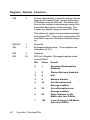
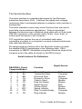
MessagePlus User’s Guide & Reference This manual covers installation and operating instructions for the following U.S. Robotics modem: • Sportster MessagePlus external modem IMPORTANT MESSAGE: This product is capable of download speeds up to 56Kbps; however, the download speeds you experience may be lower due to varying line conditions. We are continuing to test and improve our modem technology to achieve faster speeds. Visit our Web site at http://www.usr.com for future updates and enhancements. 3Com, the 3Com logo, U.S. Robotics, the USRobotics logo, and Sportster are registered trademarks and Total Control, Courier, x2 and the x2 logo are trademarks of 3Com Corp. Windows is a registered trademark of Microsoft Corp. Any other trademarks, trade names, service marks, or service names owned or registered by any other company and used in this manual are the property of their respective companies. © 1997 U.S. Robotics PCD sarl Cityparc, 3 rue Lavoisier 59650 Villeneuve d'Ascq France All Rights Reserved Table of Contents U.S. ROBOTICS : THE INTELLIGENT CHOICE IN INFORMATION ACCESS™............................................ 1 WELCOME TO X2 INFORMATION ACCESS ................ 3 PRODUCT FEATURES .................................................. 5 FAX STANDARDS ................................................................... 5 SUMMARY OF FEATURES............................................ 7 PART I : EXTERNAL MODEM INSTALLATION ............ 9 SECTION A: EXTERNAL MODEM INSTALLATION WITH WINDOWS 3.X ....................................................................... 9 How to Hook Up the Modem ...................................................10 SECTION B : EXTERNAL MODEM INSTALLATION WITH WINDOWS 95...................................................................... 11 How to connect the Modem to the Computer ..........................12 How to Move Through the “New Hardware Found” Screens....13 PART II : BEYOND SETUP .......................................... 17 SECTION A: INSTALLING FAX/DATA/VOICE SOFTWARE ....... 18 Type of Modem.......................................................................18 Initialization String ...................................................................18 Flow Control ...........................................................................19 UART - Universal Asynchronous Receiver Transmitter ...........19 (External Modems Only) .........................................................19 SECTION B : REMOTE VOICE RETRIEVAL ............................. 20 SECTION C : TROUBLESHOOTING AND ONLINE HELP RESSOURCES ..................................................................... 21 Online Help Resources.........................................................26 Are You Still Having Problems? ..........................................27 If You Must Return the Modem to Us ..................................28 SECTION D : GLOSSARY ..................................................... 29 SECTION E : TECHNICAL QUICK REFERENCE ....................... 41 Front Panel Lights (external modems).....................................41 Command Summary ...............................................................43 Command Set.........................................................................44 S-Registers.............................................................................53 The Serial Interface.................................................................61 SECTION F : LIMITED WARRANTY ........................................ 62 U.S. Robotics : The Intelligent Choice in Information Access™ ® C ongratulations! You have just purchased the Sportster MessagePlus faxmodem. Since 1976, U.S. Robotics has grown to become a key manufacturer and developer of information access technology. U.S. Robotics’ advanced technology allows you to use your faxmodem to open up a new world of information access. Now you can take advantage of the highest ™ transfer rates available today with our new x2 technology! As an innovator in the data communications field, U.S. Robotics has a history of bringing the latest technology to market at an affordable price. U.S. Robotics owns the core technology, known as the data pump, that works in its access products. This allows U.S. Robotics to bring new technologies and features to market faster and at a lower cost while passing the savings on to you. Be sure to read the following section to learn more about the latest U.S. Robotics breakthrough, x2 technology. Your new Sportster takes advantage of this technology to make connecting over analog lines faster than ever before. For more information on U.S. Robotics, visit the U.S. Robotics World Wide Web Home Page at: http://www.usr.com. User’s Guide & Reference 1 2 Sportster MessagePlus Welcome to x2 Information Access The latest breakthrough in online communications Until now, 33.6 Kbps was thought to be the practical limit for speed over standard phone lines. Now, x2 shatters that barrier, to bring you download speeds of up to 56 Kbps. However, due to FCC rules which restrict power output of your service provider’s modems, current download speeds are limited to 53Kbps. This modem is easily upgradeable to new features and enhancements as they become available. An integrated end-to-end solution from the leader U.S. Robotics is well positioned to bring you x2 technology. Our Sportster modems are the world's number one seller, and our Total ControlTM and CourierTM product lines are favored by many Internet service providers. This widespread acceptance allows U.S. Robotics to offer x2 technology to virtually anyone. Taking advantage of the modern telephone network x2 technology uses the increasingly digital telephone network to bring you faster downloads, by eliminating the analog-to-digital conversion in the downstream path. User’s Guide & Reference 3 x2 takes advantage of the typical network configuration found when an analog subscriber connects to a digitally connected server. Since x2 bypasses the analog-to-digital conversion in the downstream path, it can use nearly all of the available 64K network bandwidth. (Upstream data, typically less speed sensitive, travels at the standard V.34 rate.) The result is a completely new kind of transmission technique. Based on “encoding” rather than “modulation,” it can give you download speeds that you never thought possible. What’s more, with standard V.42 bis compression, x2 can download at speeds up to a blistering 115.2 Kbps. The new standard for online speed U.S. Robotics has already submitted x2 to the ITU-T standards committee for acceptance as the next online standard. For more information on U.S. Robotics’ x2 technology, see our World Wide Web page at http://x2.usr.com. 4 Sportster MessagePlus Product Features Your Sportster MessagePlus provides many advanced features. Here are just a few : Modulation Schemes x2 technology ITU-T V.34+ ITU-T V.34 ITU-T V.32bis ITU-T V.32 ITU-T V.23 ITU-T V.22bis ITU-T V.22 Bell 212A ITU-T V.21 Bell 103 Error Control and Data Compression Schemes ITU-T V.42 ITU-T V.42bis MNP 2-5 Fax Modulation Schemes ITU-T V.17 ITU-T V.29 ITU-T V.27ter ITU-T V.21 Fax Standards EIA 578 Class 1 FAX EIA 592 Class 2.0 FAX User’s Guide & Reference 5 Front Channel Link Rates 33333, 37333, 41333, 42666, 44000, 45333, 46666, 48000, 49333, 50666, 52000, 53333, 54666, 56000. Back Channel Link Rates 14400, 16800, 19200, 21600, 24000, 26400, 28800, 31200 V.34+ Link Rates 4800, 7200, 9600, 12000, 14400, 16800, 19200, 21600, 24000, 26400, 28800, 31200, 33600 V.32bis Link Rates 4800, 7200, 9600, 12000, 14400 Additional Link Rates 300, 1200/75 (V.23), 1200, 2400 Fax Link Rates 2400, 4800, 7200, 9600, 12000, 14400 6 Sportster MessagePlus Summary of Features Key Features of Sportster MessagePlus Sportster MessagePlus is the first product to include features that allow the user to receive fax and voice messages without the intervention of the PC. Sportster MessagePlus features a bank of Flash Memory for this purpose. Messages can be received even when the PC is not switched on. Voice messages can be retrieved from a remote location. Sportster MessagePlus comes with specially designed application software. This product is not just a normal data/fax/voice modem. The software includes all features needed to manage both Sportster MessagePlus in autonomous mode and normal fax and voice message mode. Sportster MessagePlus--• is a feature-enhanced external modem with added Flash Memory. • provides the full functionality of a standard Sportster modem. • retains incoming fax and voice messages and therefore is not just a pass through device. • is capable of receiving and storing incoming fax and voice messages without any DTE (Data Terminal Equipment) intervention. • • can transfer stored messages to the DTE (Data Terminal Equipment) at a later time. enables remotely stored voice messages to be accessed through a dialup connection. • offers a voice channel feature that includes a built-in condenser microphone. User’s Guide & Reference 7 • 8 includes software designed specifically for use with Sportster MessagePlus. The software allows the user to take full advantage of all features in the product. Other software can be used for all standard modem functions. In order to use the autonomous features, however, we recommend using the software delivered with the product. Sportster MessagePlus Part I : External Modem Installation Part I of this manual covers the installation of your external Sportster MessagePlus. The instructions are provided for both Windows 3.1/ 3.11 (hereafter jointly referred to as Windows 3.x) and Windows 95 users. Please refer to the section dealing with the operating system you use. The two sections are: Section A: External Installation with Windows 3.x (page 9) Section B: External Installation with Windows 95 (page11) Section A: External Modem Installation with Windows 3.x You’ll need these items from your Sportster MessagePlus box: modem manual phone cord serial cable power adapter User’s Guide & Reference 9 How to Hook Up the Modem 1. Turn off your computer and any attached devices, such as a printer. 2. Connect the serial cable to the modem and to the computer. When looking for the serial port label on the back of your computer, look for ports labeled COM, MODEM, RS-232, or SERIAL. DO NOT select AUX, GAME, LPT, or PARALLEL. NOTE: Remember which serial port you selected. This information will be necessary when installing your communications software. 3. Plug the power adapter into the power jack on the modem and into a standard wall outlet. 4. Plug one end of the phone cord into the telephone jack. It is labeled with a wall plug icon on the bottom of the case. Plug the other end into a phone wall jack. WARNING: The phone jack you use must be for an ANALOG phone line. Most office phones are wired through DIGITAL lines. Be sure you know what type of line you have. The modem will be damaged if you use a digital phone line. 5. If you wish to use your modem and phone through the same phone wall jack, plug your phone's cord into the modem's phone jack. It is labeled with a phone icon on the bottom of the case. Use an adapter cable if necessary. NOTE: You cannot use the modem and phone at the same time if they are sharing a line. 10 Sportster MessagePlus 6. Turn your modem on. 7. Turn your computer on. 8. Start Windows 3.x. Congratulations! You are ready to start using your Sportster MessagePlus. Section B : External Modem Installation with Windows 95 You’ll need these items from your Sportster MessagePlus box: modem phone cord manual power adapter serial cable User’s Guide & Reference 11 How to connect the Modem to the Computer 1. Turn off your computer and any attached devices, such as a printer. 2. Connect the serial cable to the modem and to the computer. When looking for your serial port label on the back of your computer, select COM, MODEM, RS-232, or SERIAL. DO NOT select AUX, GAME, LPT, or PARALLEL. Note: Remember which serial port you selected. This information will be necessary when installing your communications software. 3. Plug the power adapter into the power jack and into a standard wall outlet. 4. Plug one end of the phone cord into the telephone jack. It is labeled with a wall plug icon on the bottom of the case. Plug the other end into a phone wall jack. WARNING: The phone jack you’re going to use must be for an ANALOG phone line. Most office phones are wired through DIGITAL lines. Be sure you know what type of line you have. The modem will be damaged if you use a digital phone line. 5. If you wish to use your modem and phone through the same phone wall jack, plug your phone's cord into the modem's phone jack. It is labeled with a phone icon on the bottom of the case. Use an adapter cable if necessary. NOTE: You can not use the modem and phone at the same time if they share the same line. 12 Sportster MessagePlus 6. Turn your modem on. 7. Turn your computer on. 8. Start Windows 95. How to Move Through the “New Hardware Found” Screens 1. This screen will come up when Windows restarts. If the Driver from disk... option is not already selected, choose it. Click on the OK button. 2. Insert the driver diskinto your disk drive. 3. When you see this screen, type in A:\. (If your disk drive has a different letter name, type that letter instead of A.) User’s Guide & Reference 13 Click on the OK button. Windows will install the drivers for your new modem. 4. You can verify that the install was a success. When your desktop returns, click on the Start button and scroll up to Settings. 5. Scroll over to select Control Panel. 14 Sportster MessagePlus 6. Double-click on the Modems icon. 7. In the Modems Properties screen, you should see Sportster MessagePlus Fax External listed. This indicates that your new Sportster MessagePlus is installed correctly. User’s Guide & Reference 15 8. Click on the OK button. Congratulations! You are now ready to start using your Sportster MessagePlus. 16 Sportster MessagePlus Part II : Beyond Setup Part II includes information which may not be necessary for installing your modem or fax/data/voice software, but will help to expand your knowledge of the modem and its capabilities. The five sections are: Section A: Installing Fax/Data/Voice Software (page 18) Section B : Remote Voice Retrieval (page 20 ) Section C: Troubleshooting and Online Help Ressources (page 21) Section D: Glossary (page 29) Section E: Technical Quick Reference (page 41) Section F : Limited Warranty (page 62) User’s Guide & Reference 17 Section A: Installing Fax/Data/Voice Software Your modem has been designed and tested using a wide range of communications software packages on the market. This section will walk you through some of the details you may need to know when installing communications software packages. Type of Modem Most communications software programs will ask you to select the type of modem you are using. Select a U.S. Robotics Sportster high speed modem. If that selection is not listed, pick Courier Dual Standard, V.32bis, or V. 34. D KEY POINT: Refer to the manual that came with your software for its installation instructions. The software’s installation program will ask you questions about the modem you are using. Initialization String For hardware flow control, a fixed serial port rate and full result codes type: AT&F1<Enter> If you must use software flow control, type: AT&F2<Enter> 18 Sportster MessagePlus Flow Control • For hardware RTS/CTS. flow control (highly recommended), select • For software flow control, select XON/XOFF. NOTE: Disable the type of flow control (hardware or software) that you are not using. UART - Universal Asynchronous Receiver Transmitter (External Modems Only) 1. In DOS, at the Windows directory type: MSD 2. At the next prompt, type: C Find the UART Chip Used line and match it with the COM port column that your modem is attached to. That is your UART type. If this is your UART... Select this serial rate 16550 115.2 or 57.6 Kbps 16450 38.4 Kbps 8250 19.2 Kbps NOTE: DO NOT select a 28,800, 14,400, or 12,000 bps serial port rate if offered. Your modem will NOT work correctly with any of these settings. Fix or lock the serial port (baud) rate. If it’s referred to as autobaud, select OFF. User’s Guide & Reference 19 Section B : Remote Voice Retrieval - whilst the modem is in Independent mode - To access your Voice messages remotely, you need to dial into the Sportster MessagePlus modem. Whilst the 'outgoing message' is being played, you must enter your pre-configured password on a touch-tone telephone handset (this can be set using the software application). You have three attempts to enter the correct password. If you fail to enter the correct password, the modem will 'abort' the call and go back 'on hook'. If the correct password is entered, the modem will either emit, i) a series of short 'beeps' indicating the number of unread messages or, ii) one long 'beep' indicating there are no read/ unread messages. The user has the option to press: 0 for a repeated acoustic message count 1 to play unread messages 2 to play read messages At any time the user may abort the call by pressing the * key. The modem will automatically hang-up after a period of in-activity. 20 Sportster MessagePlus Section C : Troubleshooting and Online Help Ressources PROBLEM DIAGNOSIS POSSIBLE SOLUTION P D 1 The computer or software will not recognize the modem. D D D D Your modem might not be turned on. You may have a COM/IRQ conflict. 1 1 You might not be entering modem commands in the proper manner. 1 You may need to reset your COM and IRQ settings. 1 If using an external modem, the COM port may not be enabled. Make sure the modem is turned on. The power switch is on top of external modems. The CS light on the front panel should be lit. Check to make sure you have the correct COM port and IRQ settings in your software and/or in the Windows Control Panel. Type in all upper (AT) or lower (at) case. Refer to the diagram on the following page. Refer to your computer’s manual for information concerning enabling COM ports (usually involves altering the bios settings or motherboard jumpers). User’s Guide & Reference 21 PROBLEM DIAGNOSIS POSSIBLE SOLUTION P D 1 P P 22 The modem displays double characters on your monitor. D The modem won’t go off hook to dial or doesn’t answer the phone. Both modems exchange carrier signals but fail to establish a link. D D Both the modem and software’s local character echoes are probably turned on. You might have a bad phone cord connection to your modem. 1 The software you are using might not have auto answer enabled. You may have a poor line connection. Sportster MessagePlus 1 1 You can turn the local echo off on the modem by typing ATEO <enter> in your software’s terminal mode. To turn the local echo off in the software, refer to your software’s documentation. Make sure the phone cord is connected to the jack on the modem labeled TELCO on one end and to the wall phone jack at the other end. Check to make sure the auto answer feature is enabled. Try placing the call again. The phone company routes calls differently each time. PROBLEM DIAGNOSIS POSSIBLE SOLUTION P D 1 P Your modem won’t connect at 2400 bps with a 2400 bps modem. D Your screen keeps displaying random garbage characters. D D The modem you’re trying to connect with could be an older model that doesn’t support error control. You could have a conflict with the remote modem’s settings for word length, parity, and stop bits. Your software and modem might not be set to the same flow control settings. The best flow control settings might not be enabled on your modem. 1 1 1 You can disable error control on your modem with the following command entered in the terminal mode: AT&M0 <enter>. Now try placing the call to the remote modem again. When finished, reset your modem to enable the error control features. Type ATZ <enter> in terminal mode. Set your modem’s word lengths, parity, and stop bits the same as the remote modem or BBS you are calling. Make sure the software and modem have the same flow control settings. Type this command in terminal mode to load the optimal settings: AT&F1 <enter>. User’s Guide & Reference 23 PROBLEM DIAGNOSIS POSSIBLE SOLUTION P D 1 Your communicat ions software is reporting many cyclic redundancy check (CRC) errors and low characters per second (CPS). D D D D 24 You may have a bad phone line. Optimum flow control settings may not be enabled on your modem. The serial port rate in your communications software may be set too high for your modem’s UART or your area’s phone lines. The remote site you are dialing into may have trouble with the file transfer protocol. There may be a Terminate and Stay Resident (TSR) program running in the background, interfering with data communications. Sportster MessagePlus 1 1 1 1 Try placing the call again. The phone company routes calls differently each time. Type this command in terminal mode to load the optimum settings: AT&F1 <enter>. Lower the serial port rate in your communications software to 38,400 bps or 19,200 bps. Try using a different file transfer protocol. Do not use Xmodem if other protocols are available. Disable any TSR programs running in the background. PROBLEM DIAGNOSIS POSSIBLE SOLUTION P D 1 Errors are constantly occurring in your V.17 fax transmissio ns. D D D D P Communicat ions software fails to initialize the modem. Your modem initialization string could be insufficient for fax transmissions. You could have a disruptive Terminate and Stay Resident (TSR) program running in your background. You could have an outdated comdriver on your system. Your baud rate may be set too high. Communications software’s port settings may be incorrect. 1 1 1 1 Enter the following initialization string in your software setup screen: AT&H3&I2&R2S7=90. Disable any Terminate and Stay Resident (TSR) programs running in the background. Load the comdriver that came with your fax software. Lower baud rate to 9600. Make sure the communications software’s port settings are correctly set for your system.. User’s Guide & Reference 25 Online Help Resources Connecting to the U.S. Robotics BBS To connect to the U.S. Robotics Bulletin Board System (BBS), dial 33320910308 If this is your first time connecting to our BBS, you will be asked to enter your name and a password and to fill out a questionnaire. Internet FTP The Internet FTP provides a free library containing the same files as the BBS site. To access the FTP site type ftp.usr.com. Internet on Demand The Internet on Demand (IOD) provides automatic technical support through a library containing product information, quick reference cards, and installation help. To obtain an index of available documents, send a blank e-mail to [email protected]. To have a document e-mailed to you, place the document's number in the subject field. World Wide Web The U.S. Robotics Home Page contains the same information as the Internet on Demand listing, as well as information about U.S. Robotics. To log on to the Web, type http://www.usr.com. CompuServe Access the same information as the Internet FTP site through CompuServe. 26 Sportster MessagePlus America Online Connect to the U.S. Robotics Forum through America Online. Go to the Keyword field and type USROBOTICS to connect to the various U.S. Robotics resources, such as libraries, message boards, online customer support, and product announcements. Fax and Technical Support Hotline Technical questions about U.S. Robotics modems can also be answered via fax or by technical support representatives. Hotline: +33 (0) 3 20 19 24 24 Fax: +33 (0) 3 20 19 24 34 Are You Still Having Problems? • • • Re-read this manual, especially the Remarks on Using the Modem section. Contact your reseller who will be able to provide you with the necessary assistance. This is much more efficient and less costly than sending the modem back to us for a problem that is possibly only a simple matter of adjusting the settings. If your reseller can’t help you, contact U.S. Robotics Customer Support. When you call, specify your modem serial number (found on the outside of the box), the software being used, and if possible, the contents of your ATI7 screen. Hotline: +33 (0) 3 20 19 24 24 Fax: +33 (0) 3 20 19 24 34 USR BBS: +33 (0) 3 20 91 03 08 CompuServe: GO USROBOTICS Internet: [email protected] User’s Guide & Reference 27 If You Must Return the Modem to Us • Contact U.S. Robotics Customer Support to obtain a Return Materials Authorisation (RMA) number. You must have an RMA number before returning the modem to us. Phone : +33 (0) 3 20 87 04 97 Fax : +33 (0) 3 20 87 06 94 • Ship the unit, postage paid, in a strong box made of corrugated cardboard with plenty of packing material (preferably the original container.) • Include your RMA number, name and address on the shipping label as well as inside the package. • Ship to the following address: U.S. Robotics Logistics sarl European Repair Center RMA# Rue Jules Verne Centre de Gros N°2 F-59818 Lesquin Cedex France 28 Sportster MessagePlus Section D : Glossary Cross references are printed in boldface. Cross references with items in the Command Summary, found in Section D: Technical Quick Reference, are printed in italics. analog loopback A modem self-test in which data from the keyboard or an internal test pattern is sent to the modem's transmitter, turned into analog form, looped back to the receiver, and converted back into digital form. analog signals A variety of signals and wavelengths that can be transmitted over communications lines such as the sound of a voice over the phone line. Contrast with digital signals. answer mode The mode used by your modem when answering an incoming call from an originating modem. The transmit/receive frequencies are the reverse of the originating modem, which is in originate mode. application A computer program designed to perform a specific function, such as a word processing or organizing data into a spreadsheet. ARQ Automatic Repeat reQuest. A general term for a function that automatically allows your modem to detect flawed data and retransmit it. See MNP and V.42. ASCII American Standard Code for Information Interchange. A code used to represent letters, numbers, and special characters, such as $, !, and /. User’s Guide & Reference 29 asynchronous transmission Data transmission in which the length of time between transmitted characters may vary. Because the time lapses between transmitted characters are not uniform, the receiving modem must be signaled as to when the data bits of a character begin and when they end. The addition of start/stop bits to each character serves this purpose. Auto Answer Sets the modem to pick up the phone line when it detects a certain number of rings. See S-register S0 in Section D: Technical Quick Reference. auto dial A process where your modem dials a call for you. The dialing process is initiated by sending an ATDT (dial tone) or ATDP (dial pulse) command followed by the telephone number to dial. Auto dial is used to dial voice numbers. See command Dn. baud rate A term used to measure the speed of an analog transmission from one point to another. Although not technically accurate, baud rate is commonly used to mean bit rate. binary digit A 0 or 1, reflecting the use of the binary numbering system. Used because the computer recognizes either of two states, OFF or ON. The shortened form of binary digit is bit. bit rate Also referred to as transmission rate The number of binary digits, or bits, transmitted per second (bps). Communications channels using telephone channel modems are established at set bit rates, commonly 2400, 4800, 9600, 14,400, 28,800 and higher. bits per second (bps) The bits (binary digits) per second rate. Thousands of bits per second are expressed as kilobits per second or Kbps. 30 Sportster MessagePlus buffer A memory area set aside to be used as temporary storage during input and output operations. An example is the modem's command buffer. byte A group of binary digits stored and operated upon as a unit. In user documentation, the term usually refers to 8-bit units or characters. One kilobyte (KB) is equal to 1,024 bytes or characters; 640 KB indicates 655,360 bytes or characters. carrier A tone signifying a connection the modem can alter to communicate data across telephone lines. character A representation, coded in binary digits, of a letter, number, or other symbol. characters per second (CPS) A data transfer rate generally estimated from the bit rate and the character length. For example, at 2400 bps, 8-bit characters with start/stop bits (for a total of ten bits per character) will be transmitted at a rate of approximately 240 characters per second (cps). Some protocols, such as error-control protocols, employ advanced techniques such as longer transmission frames and data compression to increase cps. class 1 and 2.0 International standards used between fax application programs and faxmodems for sending and receiving faxes. cyclic redundancy checking (CRC) An error-detection technique consisting of a test performed on each block or frame of data by both sending and receiving modems. The sending modem inserts the results of its tests in each data block in the form of a CRC code. The receiving modem compares its results with the received CRC code and responds with either a positive or negative acknowledgment. User’s Guide & Reference 31 data communications A type of communications in which computers are able to exchange data over an electronic medium. data compression table A table containing values assigned for each character during a call under MNP5 data compression. Default values in the table are continually altered and built during each call: The longer the table, the more efficient throughput gained. data mode The mode in which the faxmodem is capable of sending and receiving data files. A standard modem without fax capabilities is always in data mode. DCE Data Communications (or Circuit-Terminating) Equipment, such as dial-up modems that establish and control the data link via the telephone network. default Any setting assumed, at startup or reset, by the computer's software and attached devices. The computer or software will use these settings until changed by the user or other software. detect phase In the ITU-T V.42 error-control protocol, the first stage in establishing if both modems attempting to connect have V.42 capability. dictionary The term used for compression codes built by the V.42 bis data compression algorithm. digital loopback A test that checks the modem's RS-232 interface and the cable that connects the terminal or computer and the modem. The modem receives data (in the form of digital signals) from the computer or terminal, and immediately returns the data to the screen for verification. digital signals 32 Sportster MessagePlus Discrete, uniform signals. In this manual, the term refers to the binary digits 0 and 1. Contrast with analog signals. DTE Data Terminal (or Terminating) Equipment. A computer that generates or is the final destination of data. duplex Indicates a communications channel capable of carrying signals in both directions. See half duplex, full duplex. Electronic Industries Association (EIA) Group which defines electronic standards in the U.S. error control Various techniques that check the reliability of characters (parity) or blocks of data. V.42 and MNP error-control protocols use error detection (CRC) and retransmission of flawed frames (ARQ). facsimile A method for transmitting the image on a page from one point to another. Commonly referred to as fax. fax mode The mode in which the faxmodem is capable of sending and receiving files in a facsimile format. See definitions for V.17, V.27ter, V.29. flow control A mechanism that compensates for differences in the flow of data into and out of a modem or other device. See commands &Hn, &In, &Rn. frame A data communications term for a block of data with header and trailer information attached. The added information usually includes a frame number, block size data, error-check codes, and Start/End indicators. User’s Guide & Reference 33 full duplex Signal will flow in both directions at the same time over one line. In microcomputer communications, may refer to the suppression of the online local echo. half duplex Signals will flow in both directions, but only one way at a time. In microcomputer communications, may refer to activation of the online local echo, which causes the modem to send a copy of the transmitted data to the screen of the sending computer. Hz Hertz, a frequency measurement unit used internationally to indicate cycles per second. ITU-T An international organization that defines standards for telegraphic and telephone equipment. For example, the Bell 212A standard for 1200-bps communication in North America is observed internationally as ITU-T V.22. For 2400-bps communication, most U.S. manufacturers observe V.22 bis. The initials ITU-T represent the French name. In English it is known as the International Telegraph and Telephone Consultative Committee. LAPM Link Access Procedure for Modems. An error-control protocol defined in ITU-T Recommendation V.42. Like the MNP protocols, LAPM uses cyclic redundancy checking (CRC) and retransmission of corrupted data (ARQ) to ensure data reliability. local echo A modem feature that enables the modem to display keyboard commands and transmitted data on the screen. See command En. MNP Microcom Networking Protocol, an error-control protocol developed by Microcom, Inc., and now in the public domain. There are several different MNP protocols, but the most commonly used one ensures error-free transmission through error detection (CRC) and retransmission of erred frames. modem 34 Sportster MessagePlus A device that transmits/receives computer data through a communications channel such as radio or telephone lines. It also changes signals received from the phone line back to digital signals before passing them to the receiving computer. nonvolatile memory (NVRAM) User-programmable random access memory whose data is retained when power is turned off. On the Sportster, it includes four stored phone numbers and the modem settings. off/on hook Modem operations that are the equivalent of manually lifting a phone receiver (taking it off-hook) and replacing it (going on-hook). online fall back/fall forward A feature that allows high-speed, error-control modems to monitor line quality and fall back to the next lower speed in a defined range if line quality diminishes. As line conditions improve, the modems switch up to the next higher speed. originate mode The mode used by your modem when initiating an outgoing call to a destination modem. The transmit/receive frequencies are the reverse of the called modem, which is in answer mode. originate mode The mode used by your modem when initiating an outgoing call to a destination modem. The transmit/receive frequencies are the reverse of the called modem, which is in answer mode parity A simple error-detection method that checks the validity of a transmitted character. Character checking has been surpassed by more reliable and efficient forms of error checking, including V.42 and MNP 2-4 protocols. Either the same type of parity must be used by two communicating computers, or both may omit parity. protocol A system of rules and procedures governing communications between two or more devices. Protocols vary, but communicating devices must follow the same protocol in order to exchange data. The format of the data, readiness to receive or send, error detection and error correction are some of the operations that may be defined in protocols. User’s Guide & Reference 35 RAM Random Access Memory. Memory that is available for use when the modem is turned on, but that clears of all information when the power is turned off. The modem's RAM holds the current operational settings, a flow control buffer, and a command buffer. remote digital loopback A test that checks the phone link and a remote modem's transmitter and receiver. remote echo A copy of the data received by the remote system, returned to the sending system, and displayed on the screen. Remote echoing is a function of the remote system. ROM Read Only Memory. Permanent memory, not user-programmable. serial transmission The consecutive flow of data in a single channel. Compare to parallel transmissions where data flows simultaneously in multiple channels. start/stop bits The signaling bits attached to a character before and after the character is transmitted during asynchronous transmission. terminal A device whose keyboard and display are used for sending and receiving data over a communications link. Differs from a microcomputer or a mainframe in that it has little or no internal processing capabilities. terminal mode Software mode that allows direct communication with the modem. Also known as command mode. 36 Sportster MessagePlus throughput The amount of actual user data transmitted per second without the overhead of protocol information such as start/stop bits or frame headers and trailers. Compare with characters per second. V.8 The ITU-T standard specification that covers the initial handshaking process. V.17 fax An ITU-T standard for making facsimile connections at 14,400 bps, ,12,000 bps, 9600 bps, 7200 bps. V.21 An ITU-T standard for modems operating in asynchronous mode at speeds up to 300 bps, full-duplex, on public switched telephone networks. V.22 An ITU-T standard for modem communications at 1200 bps, compatible with the Bell 212A standard observed in the U.S. and Canada. V.22 bis An ITU-T standard for modem communications at 2400 bps. The standard includes an automatic link negotiation fallback to 1200 bps and compatibility with Bell 212A/V.22 modems. V.27 ter An ITU-T standard for facsimile operations modulation at 4800 bps, with fallback to 2400 bps. V.29 An ITU-T standard for facsimile operations modulation at 9600 bps, with fallback to 7200 bps. that specifies that specifies V.32 An ITU-T standard for modem communications at 9600 bps and 4800 bps. V.32 modems fall back to 4800 bps when line quality is impaired. User’s Guide & Reference 37 V.32 bis An ITU-T standard that extends the V.32 connection range: 4800, 7200, 9600, 12,000, and 14,400 bps. V.32 bis modems fall back to the next lower speed when line quality is impaired, fall back further as necessary, and also fall forward (switch back up) when line conditions improve. See online fall back/fall forward. V.34 An ITU-T standard that currently allows data rates as high as 28,800 bps. V.34+ An enhancement to V.34 that enables data transfer rates as high as 33,600 bps. V.42 An ITU-T standard for modem communications that defines a twostage process of detection and negotiation for LAPM error control. V.42 bis An extension of ITU-T V.42 that defines a specific data compression scheme for use during V.42 connections. Xmodem The first of a family of error control software protocols used to transfer files between modems. These protocols are in the public domain and are available from many bulletin board services. XON/XOFF Standard ASCII control characters used to tell an intelligent device to stop/resume transmitting data. Ymodem An error-checking protocol that can send several files of data at a time in 1024-byte (1K) blocks. This protocol can use either checksums or CRC for error checking. 38 Sportster MessagePlus Ymodem G Similar to Ymodem, except it includes no error checking, which makes it faster. Zmodem Similar to Xmodem and Ymodem, except it includes batch transfer, the ability to recover from a partially complete transfer, an autostart feature, and improved efficiency. User’s Guide & Reference 39 Section E : Technical Quick Reference Section D includes information about: • • • • Front Panel Lights Command Summary S-Registers The Serial Interface (cable information) Front Panel Lights (external modems) Symbol Meaning Status AA.......... Auto Answer Answer mode: ON when register S0 is set to 1 or higher (Auto Answer), and when answering a call; OFF when modem originates a call. Light flashes when there is an incoming call. CD ......... Carrier Detect ON if modem receives a valid data signal (carrier) from a remote modem, indicating that data transmission is possible. Always ON if CD override is ON (&C0). RD ......... Received Data Flashes when modem sends result codes or passes received data bits from remote. SD ......... Send Data Flashes when computer sends a data bit to modem. TR.......... Data Terminal Ready ON if modem receives a DTR signal from computer. Always ON (modem ignores DTR) if the DTR override is ON (&D0). CS ......... Clear to Send ON until modem lowers CTS when Transmit Data hardware flow control is enabled (&H1, &H3). User’s Guide & Reference 41 Symbol ARQ/ Meaning Status Error Control/ FAX ....... Fax Operations...............Data Mode: Automatic Repeat Request. ON if modem is set to &M4 or &M5 and successfully establishes an error control connection. Flashes when modem retransmits data to remote modem. Fax Mode: Flashes to indicate fax mode. MessagePlus: Dual color LED with green indicating MessagePlus is enabled and red indicating it is off. Solid green indicates no new messages. Each new message will be indicated by a single slow blink. Fast blinking indicates that the flash memory is full. OH........... Off Hook.........................ON when modem accesses the phone line. Off when modem is On Hook. 42 Sportster MessagePlus Command Summary • • • • • Type commands in either upper or lower case, not a combination. Use the Backspace key to delete errors. (You cannot delete the original AT command since it is stored in the modem buffer.) If a command has numeric options and you don’t include a number, zero is assumed. For example, if you type ATB, the command ATB0 is assumed. Every command except A/ and +++ must begin with the AT prefix and be entered by pressing <Enter>. • • The maximum command length is 58 characters. This does not include the AT prefix, carriage returns, or spaces. Note: All defaults are based on the &F1, the Hardware Flow Control template loaded in NVRAM when the modem is shipped. Defaults are listed in italics. User’s Guide & Reference 43 Command Set $ Use in conjunction with D, S, or & commands (or just AT) to display a basic command list; online help. A Manual Answer: goes off hook in answer mode. Pressing any key aborts the operations. A/ Re-executes the last issued command. Used mainly to redial. This does not require the AT prefix or a Carriage Return. Any key Aborts off-hook dial/answer operation and hangs up. AT Required command prefix, except with A/ and +++. Use alone to test for OK result code. Bn U.S./ITU-T answer sequence. B0 ITU-T answer sequence B1 U.S. answer tone Dn Dials the specified phone number. Includes the following: L Dials the last dialed number. P Pulse (rotary) dial R Originates call using answer (reverse) frequencies. Sn Dials the phone number string stored in NVRAM at position n (n = 0−3). Phone numbers are stored with the &Zn=s command. T Tone dial , (Comma) Pause, See S8 definition; which it’s linked to. ; (Semicolon) Return to Command mode after dialing. “ Dials the letters that follow (in an alphabetical phone number). ! (Exclamation point) Flashes the switch hook. / Delays for 125 ms. before proceeding with dial string. 44 Sportster MessagePlus W @ $ Wait for second dial tone (X2 or X4); linked to S6 register. Dials, waits for quiet answer, and continues (X3 or higher). Displays a list of Dial commands. En Sets local echo. E0 Echo OFF E1 Modem displays keyboard commands Fn Sets online local echo of transmitted data ON/OFF. F0 Local echo ON. Modem sends a copy of data it sends to the remote system to your screen. F1 Local echo OFF. Receiving system may send a remote echo of data it receives. Hn Controls ON/OFF hook. H0 Hangs up (goes on hook). H1 Goes off hook. In Displays the following information. I0 Four-digit product code I1 Results of ROM checksum I2 Results of RAM checksum I3 Product type I4 Current modem settings I5 Nonvolatile memory (NVRAM) settings I6 Link diagnostics I7 Product configuration I8 Blacklist I11 Link Diagnostics Ln Controls speaker volume (internals only). L0 Low volume L1 Low volume L2 Medium volume L3 High volume Operates speaker. M0 Speaker always OFF. M1 Speaker ON until CONNECT. M2 Speaker always ON. M3 Speaker ON after dial, until CONNECT. Mn User’s Guide & Reference 45 On Returns online. O0 Returns online. O1 Returns online and retrains. P Sets pulse dial (for phone lines that don’t support touch-tone dialing). Qn Displays/suppresses result codes. Q0 Displays result codes. Q1 Quiet mode; no result codes. Q2 Displays result codes only in Originate mode. Sr.b=n Sets bit .b of register r to n (0/OFF or 1/ON). Sr=n Sets register r to n. Sr? Displays contents of S-Register r. S$ Displays a list of the S-Registers. T Sets tone dial. Vn Displays verbal/numeric result codes. V0 Numeric codes V1 Verbal codes Xn Sets result code displayed. Default is X4. 46 Sportster MessagePlus Xn Setting Result Codes X0 X1 X2 X3 X4 155/CONNECT 33600 • • • • • 180/CONNECT 33333 • • • • • 184/CONNECT 37333 • • • • • 188/CONNECT 41333 • • • • • 192/CONNECT 42666 • • • • • 196/CONNECT 44000 • • • • • 200/CONNECT 45333 • • • • • 204/CONNECT 46666 • • • • • 208/CONNECT 48000 • • • • • 212/CONNECT 49333 • • • • • 216/CONNECT 50666 • • • • • 220/CONNECT 52000 • • • • • 224/CONNECT 53333 • • • • • 228/CONNECT 54666 • • • • • 232/CONNECT 56000 • • • • • 236/CONNECT 57333 • • • • • • • • Wait for 2nd Dial Tone (W) • • Wait for Answer (@) • • Fast Dial • • Adaptive Dialing *Requires @ in dial string; replaces NO CARRIER User’s Guide & Reference 47 Yn Selects power-on/reset default configuration. Y0 Default is profile 0 setting in NVRAM Y1 Default is profile 1 setting in NVRAM Z Resets modem. Z0 Resets modem to NVRAM profile selected by Y command or dip 7. Z1 Resets modem to NVRAM profile 0 Z2 Resets modem to NVRAM profile 1 Z3 Resets modem to factory default profile 0 (&F0) Z4 Resets modem to factory default profile 1 (&F1) Z5 Resets modem to factory default profile 2 (&F2) &A Displays a list of ampersand (&) commands. &An Enables/disables additional result code subsets. See Xn. &A0 ARQ result codes disabled &A1 ARQ result codes enabled &A2 V.32 modulation indicator added &A3 Protocol indicators added LAPM/MNP/NONE (error control) and V42bis/MNP5 (data compression) &Bn Manages modem’s serial port rate. &B0 Variable, follows connection rate &B1 Fixed serial port rate &B2 Fixed in ARQ mode, variable in non-ARQ mode &Cn Controls Carrier Detect (CD) signal. &C0 CD override &C1 Normal CD operations &Dn Controls Data Terminal Ready (DTR) operations. &D0 DTR override &D1 DTR toggle causes online Command mode &D2 Normal DTR operations &D3 Resets on receipt of DTR 48 Sportster MessagePlus &Fn Loads a read-only (non-programmable) factory configuration. &F0 Generic template &F1 Hardware flow control template &F2 Software flow control template &Gn Sets Guard Tone. &G0 No guard tone, U.S. and Canada &G1 550 Hz guard tone, some European countries, requires B0 setting. &G2 1800 Hz guard tone, U.K., requires B0 setting. &Hn Sets Transmit Data (TD) flow control. See also &Rn. &H0 Flow control disabled &H1 Hardware flow control, Clear to Send (CTS) &H2 Software flow control, XON/XOFF &H3 Hardware and software flow control &In Sets Receive Data (RD) software flow control. See also &Rn. &I0 Software flow control disabled &I1 XON/XOFF signals to your modem and remote system &I2 XON/XOFF signals to your modem only &Kn Enables/disables data compression. &K0 Data compression disabled &K1 Auto enable/disable &K2 Data compression enabled &K3 MNP5 compression disabled &Mn Sets Error Control (ARQ) for connections at 1200 bps and higher. &M0 Normal mode, error control disabled &M1 Reserved &M2 Reserved &M3 Reserved &M4 Normal/ARQ &M5 ARQ mode User’s Guide & Reference 49 &Nn Sets connect speed. If connection cannot be established at this speed, the modem will hang up. Sets ceiling connect speed if &Un is greater than 0. See &Un. &N0 Variable rate &N1 300 bps &N2 1200 bps &N3 2400 bps &N4 4800 bps &N5 7200 bps &N6 9600 bps &N7 12,000 bps &N8 14,400 bps &N9 16,800 bps &N10 19,200 bps &N11 21,600 bps &N12 24,000 bps &N13 26,400 bps &N14 28,800 bps &N15 31,200 bps &N16 33,600 bps &N17 33,333 bps &N18 37,333 bps &N19 41,333 bps &N20 42,666 bps &N21 44,000 bps &N22 45,333 bps &N23 46,666 bps &N24 48,000 bps &N25 49,333 bps &N26 50,666 bps &N27 52,000 bps &N28 53,333 bps &N29 54,666 bps &N30 56,000 bps &N31 57,333 bps &Pn Sets pulse (rotary) dial make/break ratio. &P0 U.S./Canada ratio, 39%/61% &P1 U.K. ratio, 33%/67% 50 Sportster MessagePlus &Rn Sets Receive Data (RD) hardware flow control, Request to Send (RTS). See also &Hn. &R0 Reserved &R1 Modem ignores RTS &R2 Received Data to computer only on RTS &Sn Controls Data Set Ready (DSR) operations. &S0 DSR override; always ON &S1 Modem controls DSR &Tn Begins test modes. &T0 Ends testing &T1 Analog Loopback &T2 Reserved &T3 Local Digital Loopback &T4 Enables Remote Digital Loopback &T5 Prohibits Remote Digital Loopback &T6 Initiates Remote Digital Loopback &T7 Remote Digital with self-test and error detector &T8 Analog Loopback with self-test and error detector &Un Sets floor connect speed when &Un is set greater than 0. &Nn is the ceiling connect speed. See &Nn. &U0 Disabled &U1 300 bps &U2 1200 bps &U3 2400 bps &U4 4800 bps &U5 7200 bps &U6 9600 bps &U7 12,000 bps &U8 14,400 bps &U9 16,800 bps &U10 19,200 bps &U11 21,600 bps &U12 24,000 bps &U13 26,400 bps &U14 28,800 bps &U15 31,200 bps &U16 33,600 bps User’s Guide & Reference 51 &U17 &U18 &U19 &U20 &U21 &U22 &U23 &U24 &U25 &U26 &U27 &U28 &U29 &U30 &U31 &Wn 33,333 bps 37,333 bps 41,333 bps 42,666 bps 44,000 bps 45,333 bps 46,666 bps 48,000 bps 49,333 bps 50,666 bps 52,000 bps 53,333 bps 54,666 bps 56,000 bps 57,333 bps Writes current configuration to NVRAM templates. &W0 Modifies the NVRAM 0 template (Y0) &W1 Modifies the NVRAM 1 template (Y1) &Yn Sets break handling. &Y0 Destructive, but doesn’t send break &Y1 Destructive, expedited &Y2 Nondestructive, expedited &Zn=s Writes phone number string s NVRAM at position n (n = 0−3). &Zn=L Writes last executed dial string to NVRAM at position n (n = 0−3). &Zn? Displays the phone number stored at position n (n = 0−3). &ZL? Displays the last executed dial string. +++ 52 Escapes to online-command mode. Sportster MessagePlus S-Registers To change a setting, use the ATSr=n command, where r is the register and n is a decimal value from 0 − 255 (unless otherwise indicated). Register Default Function S0 0 Sets the number of rings on which to answer in Auto Answer Mode. When set to 0, Auto Answer is disabled. S1 0 Counts and stores the number of rings from an incoming call. (S0 must be greater than 0.) S2 43 Stores the ASCII decimal code for the escape code character. Default character is +. A value of 128 – 255 disables the escape code. S3 13 Stores the ASCII code for the Carriage Return character. Valid range is 0 – 127. S4 10 Stores the ASCII decimal code for the Line Feed character. Valid range is 0 – 127. S5 8 Stores the ASCII decimal code for the Backspace character. A value of 128−255 disables the Backspace key’s delete function. S6 2 Sets the number of seconds the modem waits before dialing. If Xn is set to X2 or X4, this is the time-out length if there isn't a dial tone. S7 60 Sets the number of seconds the modem waits for a carrier. May be set for much longer duration if, for example, the modem is originating an international connection. User’s Guide & Reference 53 Register Default Function S8 2 Sets the duration, in seconds, for the pause (,) option in the Dial command. S9 6 Sets the required duration, in tenths of a second, of the remote modem’s carrier signal before recognition by the Sportster. S10 7 Sets the duration, in tenths of a second, that the modem waits to hang up after loss of carrier. This guard time allows the modem to distinguish between a line disturbance from a true disconnect (hang up) by the remote modem. While we don’t recommend connecting the modem to a line with call waiting, if you have it, you may wish to adjust this setting upward to prevent the modem from misinterpreting the second call signal as a disconnect by the remote modem. 7 A better alternative is to ask your phone company how to temporarily disable call waiting (usually *70W). For example: ATDT *70W phone number. NOTE: If you set S10 = 255, the modem will not hang up when carrier is lost. Dropping DTR hangs up the modem. S11 70 Sets the duration and spacing, in milliseconds, for tone dialing. S12 50 Sets the duration, in fiftieths of a second, of the guard time for the escape code sequence (+++). 54 Sportster MessagePlus Register Default Function S13 Bit-mapped register. Select the bit(s) you want on and set S13 to the total of the values in theValue column. For example, ATS13 = 17 enables bit 0 (value is 1) and bit 4 (value is 16). 0 Bit 0 1 Value 1 2 2 3 4 8 4 16 5 6 7 32 64 128 Result Reset when DTR drops. Reset non-MNP transmit buffer from 1.5K to 128 bytes.* Set backspace key to delete. On DTR signal, auto dial the number stored in NVRAM at position 0. At power on/reset, Auto Dial the number stored in NVRAM at position 0. Reserved Disable quick retrains. Disconnect on escape code. * The 1.5K-byte non-ARQ buffer allows data transfer with Xmodem- and Ymodem-type file transfer protocols without using flow control. The 128-byte option lets remote users with slower modems keep data you’re sending from scrolling off their screens. When remote users send your computer an XOFF (Ctrl-S) and you stop transmitting, the data in transit from your modem’s buffer doesn’t exceed the size of their screen. This is also very helpful in situations when a remote modem/printer application is losing characters. User’s Guide & Reference 55 Register Default Function S14 0 Reserved S15 0 Bit-mapped register setup. To set the register, see instructions for S13. S16 0 Bit 0 1 2 Value 1 2 4 3 4 5 6 7 8 8 16 32 64 128 136 Result Disable ARQ/MNP for V.22. Disable ARQ/MNP for .22bis. Disable ARQ/MNP V.32/V.32bis/V.32terbo. Disable MNP handshake. Disable MNP level 4. Disable MNP level 3. MNP incompatibility. Disable V.42 operation. Disable V.42 detect phase. Bit-mapped register setup. To set the register, see instructions for S13. Bit 0 1 2-7 Value 1 2 4-128 Result Reserved Touch tone dialing test. Reserved S17 0 Reserved S18 0 Test timer for &T loopback testing. Sets the time in seconds of testing before the modem automatically times out and terminates the test. When set to 0, the timer is disabled. Valid range is 1-255. S19 0 Sets the duration, in minutes, for the inactivity timer. The timer activates when there is no data activity on the phone line; at time-out the modem hangs up. S19 = 0 disables the timer. S20 0 Reserved 56 Sportster MessagePlus Register Default Function S21 10 Sets the length, in 10-millisecond units, of breaks sent from the modem to the computer; applies to MNP or V.42 mode only. S22 17 Stores the ASCII decimal code for the XON character. S23 19 Stores the ASCII decimal code for the XOFF character. S24 0 Reserved S25 20 Sets the duration, in hundredths of a second, that DTR must be dropped so that the modem doesn’t interpret a random glitch as a DTR loss. (Most users will want to use the default; this register is useful for setting compatibility with older systems running under older operating software.) S26 0 Reserved S27 0 Bit-mapped register setup. To set the register, see instructions for S13. Bit 0 Value 1 1 2 2 3 4 8 4 5 6 16 32 64 Result Enables ITU-T V.21 modulation at 300 bps for overseas calls; in V.21 mode, the modem answers both overseas and domestic (U.S. and Canada) calls, but only originates V.21 calls. (Default Bell 103) Enables unencoded (non-trellis coded) modulation in V.32 mode. Disables V.32 modulation. Disables 2100 Hz answer tone to allow two V.42 modems to connect faster. Enables V.23 fallback mode. Disables V.32bis mode. Disable V.42 selective reject. User’s Guide & Reference 57 Register Default Function 7 S28 0 8 128 Software compatibility mode. This setting disables the codes and displays the 9600 code instead. The actual rate of the call can be viewed on the ATI6 screen Used for unusual software incompatibilities. Some software may not accept 7200, 12,000, and 14,400 bps or greater result codes. Eliminates the V.32 answer tones for a faster connection. Default item, all times are in tenths of seconds. 255 Disables all connections except V.32 at 9600 bps. S29 20 Sets the duration, in tenths of a second, of the V.21 answer mode fallback timer. S30 0 Reserved S31 128 Reserved S32 2 Bit mapped register setup. To set the register, see the instructions for S13. Bit 0 1 2 3 4 5 6-7 58 Sportster MessagePlus Value 1 2 4 8 16 32 64-128 Result V.8 Call Indicate enabled. Enables V.8 mode. Reserved. Disable V.34 modulation. Disable V.34+ modulation. Disable x2 modulation. Reserved Register Default Function S33 0 Bit 0 1 2 3 4 5 6 7 S34 0 Bit mapped register setup. To set the register, see the instructions for S13. Value Result 1 Disable 2400 symbol rate. 2 Disable 2743 symbol rate. 4 Disable 2800 symbol rate. 8 Disable 3000 symbol rate. 16 Disable 3200 symbol rate. 32 Disable 3429 symbol rate. 64 Reserved 128 Disable shaping. Bit mapped register setup. To set registers, see instructions for S13. Bit Value Result 0 1 1 2 2 4 3 8 Disable 8S-2D trellis encoding. Disable 16S-4D trellis encoding. Disable 32S-2D trellis encoding. Disable 64S-4D trellis encoding. Disable non-linear coding. Disable TX level deviation. Disable Pre-emphasis. Disable Pre-coding. S35 0 4 16 5 32 6 64 7 128 Reserved S36 14 Reserved S37 0 Reserved User’s Guide & Reference 59 Register Default Function S38 0 Sets an optional delay, in seconds, before a forced hang-up and clearing of the Transmit buffer when DTR drops during an ARQ call. This allows time for a remote modem to acknowledge receipt of all transmitted data before it is disconnected. The modem immediately hangs up when DTR drops. This option only applies to connections terminated by dropping DTR. If the modem receives the ATH command, it ignores S38 and immediately hangs up. S39-S40 0 Reserved S41 0 Bit mapped register setup. To set registers, see instructions for S13. S42 0 Reserved S43 112 60 SR 8-bit S-Register. Bit mapped register stored in the NVRAM. Bit Value Result 0 1 Sportster MessagePlus disabled. 1 2 Dialup Retrieval disabled. 2 4 N/A 3 8 Monitor disable. 4 16 Fax Reception and Storage enabled. 5 32 Voice Reception and Storage enabled. 6 64 (High) Answer in SR Mode after four RINGs. 7 128 (Low) Answer in SR Mode after four RINGs. Sportster MessagePlus The Serial Interface The serial interface is a standard developed by the Electronic Industries Association (EIA). It defines the signals and voltages used when data is exchanged between a computer and a modem or serial printer. The entire standard covers many more functions than are used in most data communications applications. Data is transmitted between the devices over a shielded serial cable with a 25-pin male (DB-25P) connector to the modem and a 25-pin, 9-pin, 8-pin, or custom-built connector to the computer. FCC regulations require the use of a shielded cable when connecting a modem to a computer to ensure minimal interference with radio and television. Pin assignments are factory-set in the Sportster modem to match the standard DB-25 assignments in the following table. DB-9 connectors for IBM/AT-compatible computers should be wired at the computer end of the cable as shown in the DB-9 column. Serial Interface Pin Definitions Signal Source DB-25DB-9 Circuit Computer/Modem 1 — AA 2 3 BA 3 2 BB 4 7 CA 5 8 CB 6 6 CC 7 5 AB 8 1 CF 12 — SCF 20 4 CD 22 9 CE Function Chassis Ground Transmitted Data Received Data Request to Send Clear to Send Data Set Ready Signal Ground Carrier Detect Speed Indicate Data Terminal Ready Ring Indicate Both Computer Modem Computer Modem Modem Both Modem Modem Computer Modem User’s Guide & Reference 61 Section F : Limited Warranty U.S. Robotics warrants to the original end-user purchaser that this product will be free from defects in materials and workmanship for a period of five years from the date of purchase. During the limited warranty period, and upon proof of purchase, the product will be repaired or replaced (with the same or a similar model, which may be a refurbished model) at U.S. Robotics’ option, without charge for either parts or labor. This limited warranty shall not apply if the product is modified, tampered with, misused, or subjected to abnormal working conditions (including, but not limited to, lightning and water damage). THIS LIMITED WARRANTY DOES NOT GUARANTEE YOU UNINTERRUPTED SERVICE. REPAIR OR REPLACEMENT AS PROVIDED UNDER THIS LIMITED WARRANTY IS THE EXCLUSIVE REMEDY OF THE PURCHASER. THIS LIMITED WARRANTY IS IN LIEU OF ALL OTHER WARRANTIES, EXPRESS OR IMPLIED, INCLUDING, BUT NOT LIMITED TO, ANY IMPLIED WARRANTY OF MERCHANTABILITY OR FITNESS FOR A PARTICULAR USE OR PURPOSE. U.S. ROBOTICS SHALL IN NO EVENT BE LIABLE FOR ANY SPECIAL, INDIRECT, INCIDENTAL, PUNITIVE OR CONSEQUENTIAL DAMAGES OF ANY KIND OR CHARACTER, INCLUDING, WITHOUT LIMITATION, LOSS OF REVENUE OR PROFITS, FAILURE TO REALIZE SAVINGS OR OTHER BENEFITS, LOSS OF DATA OR USE, DAMAGE TO EQUIPMENT, AND CLAIMS AGAINST THE PURCHASER BY ANY THIRD PERSON, EVEN IF U.S. ROBOTICS HAS BEEN ADVISED OF THE POSSIBILITY OF SUCH DAMAGES. This limited warranty gives you specific legal rights. You may have others, which vary from nation to nation. Some nations do not allow limitations on duration of an implied warranty, or the exclusion or limitation of incidental or consequential damages, so the above exclusion or limitation may not apply to you. 62 Sportster MessagePlus To obtain service under this limited warranty, contact the U.S. Robotics Customer support Service and ask for a RMA (Return Materials Authorisation) number. User’s Guide & Reference 63 TT dng Benelux U.S. Robotics Benelux Planetenbaan 118 3606 AK Maarsen Nederland Tel : 346.555105 Fax : 346.555318 Europe U.S Robotics PCD s.a.r.l Cityparc, 3 rue Lavoisier 59650 Villeneuve d'Ascq France Tel : +33.(0)3.20.19.24.24 Fax : +33.(0)3.20.19.24.34 2.024.208