1
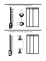
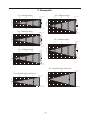
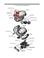
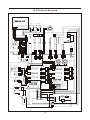
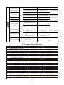
1) Open the box and checking
Page 1
2) Safety instructions
Page 1
3) Operating determinations
Page 2
4) Description of the device
Page 3
5) Installation
Page 4
6) Control Board Operation
Page 8
7) DMX512 Channel Function
Page 9
8) Technical specifications
Page 18
9) Beampath
Page 19
10)Maintenance and cleaning
Page 20
11) Structure of the fixture
Page 21
12) Electrical diagram
Page 22
13) Common faulty maintain
Page 23
14) Component antitheses
Page 24
15) Main PCB
Page 26
16) Display PCB
Page 27
17) Driver(L) PCB
Page 28
18) Driver(S) PCB
Page 29
1.Open the box and checking
Congratulations on choosing our products! Please carefully read this instruction manual in its
entirety and keep it well for using reference. This manual contained about the installation and the
relative using information of this products. Please according to this manual's relative speaking when
using this equipment.
This equipment was made of new style, high intensity plastic . It fully shows the modem times
light characteristic with beauty structure. And it was made according to CE standard. Fully up the
international standard of DMX512 agreement. Master or slave in phase control. Can be use in large
entertainment, theater, performing and playing hall, etc.
This product uses MSD 250 or MSD 250/2 electrical arc lamp. When receiving this product
please carefully bring and put; and check that whether this equipment has been damaged or not
during transportation. And please also check the following thing was enclosed:
Signal line ----------------------- one piece Safety string -----------------------one piece
User Manual-----------------------one set
Omega -holder----------------------two pieces
2. Safety instructions
Every person involved with installation and maintenance of this device have to:
- be qualilfied
- follow the instructions of this manual
CAUTION:
Ø
Ø
Ø
Ø
Ø
Ø
Keep this device away from rain and moisture!
Unplug mains lead before opening the housing!
FOR YOUR OWN SAFETY, PLEASE READ THIS USER MANUAL CAREFULLY
BEFORE YOU INITIAL START - UP!
Be careful with your operations.
With a high voltage you can suffer a dangerous electric shock when touching the
wires!
Ø This device has left our premises in absolutely perfect condition. In order to maintain
this condition and to ensure a safe operation, it is absolutely necessary for the user to
follow the safety instructions and warning notes written in this manual.
Important:
Ø T he manufacturer will not accept liability for any resulting damages caused by the nonobservance of this manual or any unauthorized modification to the device.
Ø Please consider that damages caused by manual modifications to the device are not
subject to warranty.
Ø Never let the power-cord come into contact with other cables! Handle the power-cord
and all connections with the mains with particular caution!
Ø Make sure that the available voltage is not higher than stated on the rear panel.
Ø Always plug in the power plug least. Make sure that the power-switch is set to OFFposition before you connect the device to the mains. The power-plug has to be access
able after installing the device.
Ø Make sure that the power-cord is never crimped or damaged by sharp edges. Check the
device and the power cord from time to time.
1
Ø by the plug. Never pull out the plug by tugging the power-cord.
Ø This device falls under protection class I. Therefore it is essential to connect the
yellow/green conductor to earth.
Ø The electric connection, repairs and servicing must be carried out by a qualified
employee.
Ø Do not connect this device to a dimmer pack.
Ø Do not switch the fixture on and off in short intervals as this would reduce the lamp' s
life.
Ø During the initial start-up some smoke or smell may arise. This is a normal process and
does not necessarily mean that the device is defective.
Ø Do not touch the device's housing bare hands during its operation (housing becomes hot)!
Ø For replacement use lamps and fuses of same type and rating only.
CAUTION :
EYE DAMAGES !
Avoid looking directly into the light source(meant especially for epileptics) !
3. Operating determinations
Ø This device is a moving-head spot for creating decorative effects and was designed for
indoor use only.
Ø If the device has been exposed to drastic temperature fluctuation (e.g. After transportation), do not switch it on immediately. The arising condensation water might damage
your device. Leave the device switched off until it has reached room temperature.
Ø Never run the device without lamp!
Ø Do not shake the device. Avoid brute force when installing or operating the device.
Ø Never lift the fixture by holding it at the projector-head, as the mechanics may be
damaged. Always hold the fixture at the transport handles.
Ø When choosing the installation-spot, please make sure that the device is not exposed to
extreme heat, moistureor dust. There should not be any cables lying around. You
endanger your own and the safety of others!
Ø The minimum distance between light-output and the illuminated surface must be more
than 2 meters.
Ø Make sure that the area below the installation place is blocked when rigging, derigging
or servicing the fixture. Always fix the fixture with an appropriate safety-rope. Fix the
safety-rope at the correct holes only.
Ø Only operate the fixture after having checked that the housing is firmly closed and all
screws are tightly fastened.
Ø The lamp must never be ignited if the objective-lens or any housing-cover is open, as
discharge lamps may explose and emit a high ultraviolet radiation, which may cause
burns.
Ø The maximum ambient temperature ta = 45 must never be exceeded. Otherwise, the
lamp is switched off and the fixture is out of operation for 5 minutes..
2
4.Description of the device
1 - Moving head
2 - Yoke
3- Carry handles
4 - Base
Rear panel:
5 -Power switch
6 -DMX output
7- DMX input
8- Power cord
9- Fuse holder
LAMP:MSD 250/2
MSD 250
SERIAL DATA LINK
OUT
DMX
IN
1=GND
2=SIG.3=SIG.+
POWER SWITCH
FUSE
LIGHTING CONTROL PROTOCOL:DMX512
Serial number:
POWER SUPPLY
T 3.15A@230V
T 6.3A@120V
Front panel:
10 - Mode-button
11 - Enter-button
12 - Up-button
13- Down-button
14 - Display
3
5.2 Lamp adjust
The lamp holder is aligned at the factory. Due to differences between lamps , fine
adjustment may improve light performance. Strike the lamp, open the shutter and the iris,
set the dimmer intensity onto 100% and focus the light on a flat surface (wall). As the
optimum distance of the lamp from lens was adjusted during the installing or changing the
lamp (by turning the screw "A"), it is necessary to adjust only the second position by
turning the screw "B", in order to center the hot-spot (the brightest part of the beam). If
the hot spot seems to be too bright, you can lower its intensity by moving the lamp closer to
the reflector. Do so by turning the screw "A" until the light is evenly distributed. If the
light on the edge seems to be brighter as in the center, the lamp is too close at the reflector.
In this case, you need to move the lamp away from the reflector until the light is evenly
distributed and the beam appears bright enough.
Correct
Incorrect
Optimum distance
1-1,5 mm
WARNING!
Lamp is hot! Risk of fire! Protect hands and eyes.
Wait at least 15min. Before opening the covers
and removing lamp from the fixture.
1.3m
Minimum distance to lighted object:
Maximum room temperature ta=45
Minimum distance from flammable material d=0.5m.
Exterior surface temperature T=80 .
Not for domestic use.
Adjust lamp position by turning screws
and
Be sure that the lamp
bulb never touch the lens
A
Screw¡°
B¡±
B
Disconnect the fixture from AC power
before re-lamping.
Screw A
5.3Inserting/Exchanging gobos
Turn off the lamp and allow it to cool for at least 10 minutes. Disconnect the fixture from
power. To insert the gobos open the top cover of the moving-head by loosening the 3 screws
on the top cover and follow the instructions below:
Rotating gobo-wheel:
Press the ends of the fixation-ring together with an appropriate tool and remove it.
Remove the gobo and insert the new gobo. Press the ends of the fixation-ring together and
insert it in the front of the gobo.
5
Colour/Static gobo-wheel:
Gently bend out the gobo holder to release it from the fixative holes and eject it from the
pressing snap. Press the ends of the fixation-ring together with an appropriate tool and
remove it. Remove the gobo and insert the new gobo. Press the ends of the fixation-ring
together and insert it in the front of the gobo. Put the gobo holder back under the pressing
snap and push it to the 3 fixative notches.
gobo
pressing snap
holder
5.4 Rigging the fixture
DANGER TO LIFE:Please consider the respective national norms during the
installation!The installation must only be carried out by an authorized dealer!
Ø The installation of the projector has to be built and constructed in a way that it can hold 10
times the weight for 1 hour without any harming deformation.
Ø The installation must always be secured with a secondary safety attachment, e.g. an
appropriate catch net. This secondary safety attachment must be constructed in a way that
no part of the installation can fall down if the main attachment fails.
Ø When rigging, derigging or servicing the fixture staying in the area below the installation
place, on bridges, under high working places and other endangered areas is forbidden.
Ø The operator has to make sure that safety-relating and machine-technical installations are
approved by an expert before taking into operation for the first time and after changes
before taking into operation another time.
Ø The operator has to make sure that safety-relating and machine-technical installations are
approved by an expert after every four year in the course of an acceptance test.
Ø The operator has to make sure that safety-relating and machine-technical installations are
approved by a skilled person once a year.
Ø The projector should be installed outside areas where persons may walk by or be seated.
Ø IMPORTANT! OVERHEAD RIGGING REQUIRES EXTENSIVE EXPERIENCE,
including (but not limited to)calculating working load limits, installation material being
used, and periodic safety inspection of all installationmaterial and the projector. If you
lack these qualifications, do not attempt the installation yourself, but instead use a
professional structural rigger. Improper installation can result in bodily injury and or
damage to property.
Ø The projector has to be installed out of the reach of people.
Ø If the projector shall be lowered from the ceiling or high joists, professional trussing
systems have to be used. The projector must never be fixed swinging freely in the room.
Ø Caution: Projectors may cause severe injuries when crashing down! If you have doubts
concerning the safety of a possible installation, do NOT install the projector!
Ø Before rigging make sure that the installation area can hold a minimum point load of 10
times the projector s weight.
6
Ø The projector can be placed directly on the stage floor or rigged in any orientation on a
truss without altering its operation characteristics.
Ø For overhead use, always install a safety-rope that can hold at least 10 times the weight of
the fixture. You must only use safety-ropes with screw-on carabines. Pull the safety-rope
through the two apertures on the bottom of the base and over the trussing system etc.
Insert the end in the carabine and tighten the fixation screw.
Secure chain
Mounting plate
Clamp
Omega-holde
Eye bolt
5.5 Connection to the mains
Verify the power supply settings before applying power!
If you wish to change the power supply settings,see the chapter Appendix.
Connect the fixture to the mains with the enclosed power cable and plug.
The earth has to be connected!
The occupation of the connection-cables is as follows:
Cable (EU)
Brown
Light blue
Y ellow/Green
Cable (US)
Pin
Black
White
Green
Live
Neutral
Earth
5.6 DMX-512 connection/connection between fixtures
7
International
Only use a stereo shielded cable and 3-pin XLR-plugs and connectors in order to connect the
controller with the fixture or one fixture with another.
Occupation of the XLR-connection:
DMX-input
XLR mounting-plug:
DMX-OUTPUT
XLR mounting-socket:
1- Ground
2 - Signal (-)
3 - Signal (+)
1 1 - Ground
2 - Signal (-)
3 - Signal (+)
Caution: At the last fixture, the DMX-cable has to be terminated with a terminator. Solder a
120 resistor between Signal (-) and Signal (+) into a 3-pin XLR-plug and plug it in the
DMX-output of the last fixture.
The transform of the controller line of 3 pins and 5 pins (plug and socket)
6. Control Board Operation
Function Table:
Mode
Condition
Function
Pan movement in positive or negative direction
YES--negative direction
Vertical movement in positive or negative direction YES--negative direction
Address code set
Reset
YES--reset
Rainbow color wheel change color linear or stepping YES--linear
DMX512 mode
Automatic
Slave mode
Lamp on
Lamp off
Working mode
Lamp switch
Software version
Lamp hot
Lamp error
8
Control board operation way:
LED
MODE
ENTER
UP
DOWN
1.Select working mode by pressing MODE.
2.Press ENTER to confirm the selection.
3.Press UP and DOWN to select working condition.
4.Press ENTER to confirm the selection.
7. DMX512 Channel Function
CHANNEL
FUNCTION
1
PAN
2
TILT
3
PAN FINE(proportional)
4
TILT FINE(proportional)
5
Speed of PAN/TILT movement
6
Lamp on/off & reset
7
Colors 1
8
Static gobos/colors 2
9
Prism
10
3-facet Prism rotation
11
Rotating gobos
12
Rotating gobo index, rotating gobo rotation
13
Zoom, frost, UV filter
14
Focus(proportional)
15
Shutter/ strobe
16
Dimmer intensity(proportional)
9
CHANNEL 1: PAN
Effect
Value
255
100
0
0
Clockwise 53 0
rotate
CHANNEL 2: TILT
10
Value
Effect
255
100
Anti-clockwise
280 rotate
0
0
CHANNEL 3: PAN FINE (proportional)
•
Value
Effect
255
100
Fine control of tilt
movement
0
0
CHANNEL 4: TILT FINE (proportional)
11
Value
Effect
255
100
Fine control of
tilt movement
0
0
CHANNEL 5: Speed of PAN/TILT movement
Value
Slow
Fast
Effect
255
100
0
0
Slow
fast
CHANNEL
6: Lamp on/off & reset
•
Value
12
Effect
240-255
95-100
No function
230-239
91-94
Lamp off after 3
seconds
140-229
55-90
No function
128-139
50-54
Lamp on after 3
seconds,Reset
0-127
0-49
No function
CHANNEL 7: Color1
Value
Effect
128-255
50-100
Forwards rainbow
effect from slow to fast
112-127
44-49
Pink
96-111
37-43
Blue
80-95
31-36
Orange
64-79
25-30
Green
48-63
19-24
Magenta
32-47
12-18
Yellow
16-31
6-11
Red
0-15
0-5
Open/white
Value
Effect
222-255
87-100
Light Blue
185-221
72-86
Pale purple
148-184
57-71
Light Orange
111-147
43-56
Static gobo 3
74-110
28-42
Static gobo 2
37-73
14-27
Static gobo 1
0-36
0-13
White
CHANNEL 8: Static gobo /color2
13
CHANNEL 9: Prism
Value
Effect
128-255
100
3-facet prism
0-127
0
No function
133-255
53-100
Backwards rotation
from slow to fast
128-132
51-52
No rotation
5-127
3-50
Forwards rotation
from fast to slow
0-4
0-2
No rotation
CHANNEL 10: 3-facet prism rotation
Value
14
Effect
CHANNEL 11: Rotating gobos
Effect
Value
224-255
88-100
Rotate gobo wheel
continue rotation
from slow to fast
160-223
63-87
Rotate gobo 5
128-159
50-62
Rotate gobo 4
96-127
37-49
Rotate gobo 3
64-95
25-36
Rotate gobo 2
32-63
12-24
Rotate gobo 1
0-31
0-11
Open/hole
CHANNEL 12:Rotating gobo index, rotating gobo rotation
15
Value
Effect
159-255
62-100
Backwards gobo rotation
from slow to fast
61-158
24-61
Forwards gobo rotation
from slow to fast
0-60
0-23
Gobo indexing (0-540 )
CHANNEL 13: Zoom,frost,UV filter
Effect
Value
UV-filter
224-239
87-92
Frost
208-223
82-86
Zoom 26
192-207
75-81
Zoom 24
176-191
68-74
Zoom21
160-175
62-67
Zoom 18
128-159
50-61
Zoom 15
112-127
43-49
UV-filter
96-111
37-42
Frost
80-95
31-36
Zoom 26
64-79
24-30
Zoom 24
48-63
18-23
Zoom21
32-47
12-17
Zoom 18
0-31
0-11
Zoom 15
Zoom without focus corection
93-100
Zoom without focus corection
240-255
CHANNEL 14: Focus(proportional)
Near
Far
16
Value
Effect
255
100
close distance
0
0
far distance
CHANNEL 15:Shutter, strobe
Value
Effect
224-255
87-100
Shutter Open
192-223
75-86
Random strobeeffect from slow
to fast
160-191
62-74
Shutter Open
128-159
50-61
Pulse-effect in
sequences from
slow to fast
96-127
37-49
Shutter Open
64-95
25-36
Strobe-effect from
slow to fast (max
10flashes/s)
32-63
12-24
Shutter Open
0-31
0-11
Shutter closed
CHANNEL 16: Dimmer intensity(proportional)
Brightest
Value
Effect
255
100
Brightest
0
0
Black
Black
17
8. Technical specifications
US-model: Voltage............................AC100/110/120V , 50/60Hz
Fuse................................ T 6.3 A@120V
EU-model:Voltage............................AC220/230/240V ,50/60Hz
Fuse ................................T3.15A @230V
Rated Power 350W
DMX512 Channel 16CHS
Luminous
18000 LM
Lamp: Philips MSD250/2 or MSD 250 GY 9,5
Optical System:
- Focus: Linear electric focus
- Zoom: Motorized multi-step-zoom with five different apertures (15
24 , 26 )
,
18
, 21
,
Color:
- 7dichroic-filters plus white,colour-wheel with variable rotation speed in both directions
Strobe: Variable speed (1-10 flashes/sec)
Rigging:
-Stands directly on the floor
-Mounts horizontally or vertically with 2 clamps
-1 truss orientation
-Safety chain/cord attachment bolt
Temperatures
-Maximum ambient temperature ta : 45
-Maximum housing temperature tb (steady state): 80
Minimum distances:
-Min.distance from flammable surfaces: 0.5m
-Min.distance to lighted object: 2.0m
Dimmer: Smooth dimmer 0-100%
Pan / Tilt Movement:
-Pan 530 , Tilt 280
-Micro-step scan effect
-Auto-repositioning by photoelectric repositioning system
-Linearity move speed adjust.
Prisms: 3-facet prism (dual direction rotation with adjustable speed)
Dimensions and weight:
-Length of base (including handles): 400 mm
-Width of yoke: 400 mm
-Height (head horizontal): 476 mm
-Weight (net): 26 kg
18
9. Beampath
15
24
radiation angle
92
990
41
440
23 Foot-candles
250 LUX
3
5
2
4
1
3
Beam opening (m)
Beam opening (m)
369
3970
0
1
2
3
5
1,30
10
2,63
15
3,95
20 Distance(m)
5,27 Diameter(m)
radiation angle
180
1940
45
485
20
215
5
2,13
10
4,25
15
6,38
11 Foot-candles
120 LUX
2
1
0
1
2
3
18
281
3020
4
radiation angle
70
755
33
355
4
5
18 Foot-candles
190 LUX
20 Distance(m)
8,50 Diameter(m)
Beam opening (m)
3
2
1
0
26
1
2
5
3
37
395
16
175
9 Foot-candles
100 LUX
5
2,30
10
4,62
15
6,93
20 Distance(m)
9,20 Diameter(m)
4
5
1,58
21
241
2600
4
10
3,17
15
4,75
20 Distance(m)
6,34 Diameter(m)
radiation angle
60
650
27
290
3
Beam opening (m)
4
15 Foot-candles
160 LUX
3
Beam opening (m)
radiation angle
147
1580
2
1
0
1
2
3
2
4
1
5
0
1
2
3
4
5
1,85
10
3,70
15
5,56
20 Distance(m)
7,41 Diameter(m)
26
5
Beam opening (m)
3
223
2400
56
600
25
267
24
256
11
114
5
2,49
10
4,99
15
7,48
6 Foot-candles
65 LUX
3
14 Foot-candles
150 LUX
2
1
0
1
2
1
0
1
2
3
2
3
95
1024
4
radiation angle with frost
Beam opening (m)
15
radiation angle with frost
4
5
1,49
10
2,99
15
4,48
5
20 Distance(m)
5,98 Diameter(m)
19
20 Distance(m)
9,97 Diameter(m)
10. Maintenance and cleaning
It is absolutely essential that the fixture is kept clean and that dust, dirt and smoke-fluid
residues must not buildup on or within the fixture. Otherwise, the fixtures light-output will
be significantly reduced. Regular cleaning willnot only ensure the maximum light-output,
but will also allow the fixture to function reliably throughout its life.A soft lint-free cloth
moistened with any good glass cleaning fluid is recommended, under no circumstances
should alcohol or solvents be used!
DANGER :Disconnect from the mains before starting anymaintenance work
The front objective lens will require weekly cleaning as smoke-fluid tends to building up
residues, reducing thelight-output very quickly. The cooling-fans should be cleaned
monthly.
The gobos may be cleaned with a soft brush. The interior of the fixture should be cleaned
at least annually usinga vacuum-cleaner or an air-jet.
The dichroic colour-filters, the gobo-wheel and the internal lenses should be cleaned
monthly.
To ensure a proper function of the gobo-wheel , we recommend lubrication in six month
intervals. The quantity of oil must not be excessive in order to avoid that oil runs out when
the gobo-wheel rotates.
There are no serviceable parts inside the device except for the lamp and the fuse.Please
refer to the instructions under "Fitting/Exchanging the lamp".Maintenance and service
operations are only to be carried out by authorized dealers.
Replacing the fuse
If the lamp burns out, the fine-wire fuse of the device might fuse, too. Only replace the
fuse by a fuse of same type and rating.Before replacing the fuse, unplug mains lead.
Procedure:
1) Unscrew the fuseholder on the rear panel of the base with a fitting screwdriver from the
housing (anti- clockwise).
2) Remove the old fuse from the fuseholder.
3) Install the new fuse in the fuseholder.
4) Replace the fuseholder in the housing and fix it.
20
11. Structure of the fixture
Light shield board
Top cover
Lamp
light head Fan
Color wheel
Lamp holder
Rotathng gobo wheel
Reflector
Stathc gobo wheel
Tilt motor
Belt
Driver Board L
Arm
Driver Board S
Display Board
Transformer
Capacitance
Bottom Fan
Ballast
DMX512socket
Seat cover
Pan Motor
Main PCB
21
12. Electrical diagram
DISPLAY PCB
DMX IN
DMX OUT
2
1
1
2
DISPLAY CPU
RED
3
3
BLUE
BOTTOM 12VDC FAN
11VAC
7805
75176
3
2
1
Transmission line
Ic11
Ic1
Ic4
Ic3
Ic2
RELAY
+
S
Ic12
-
+
S
+
S
-
S2
S1
S1
S2
Ic7
3771
-
Ic6
+
TILT
Sensor
1
MAIN PCB
S
TILT
Horge
2
Ic5
+
Horae 3C PCB
FOCUS
573
3
Ic8
Ic9
Ic10
MOTOR4
MOTOR5
CPU
24VAC
+
-
+
S1
S2
12V
DC
-
0V
+
-
S2
S1
S1
S2
-
PAN
Sensor
30V12V 0V DC
+
MOTOR3
+
-
S2
S1
MOTOR1 MOTOR2
PAN
Horge
Pan
Tilt
Focus
Shutter1 Shutter2
30VDC
LIGHT HEAD
12VDC FAN
2Pcs
12VDC
0VDC
0VDC
12VDC
30VDC
BLUE
Horae 4 PCB
Rotation gobo wheel
Gobo
wheel
-
Ic13
Ic21
Ic24
Ic22
Ic25
Gobo MOTOR7
rotation
+
+
S
7805
Horae 3B PCB
Colour
Prism
wheel
-
Ic17
+
S gobo
S colour
RED
MOTOR6
Ic14
Prism MOTOR11
rotation
Ic18
+
S
7805
Mix
gobos
MOTOR8
Zoom
-
S
+
Ic15
Ic19
Horae 5 PCB
Zoom
S+
Ic26
Ic23
MOTOR9
2107S PCB
Colour
+
S
Ic16
375
Ic20
8CPU
5E77
2107L PCB
POWER SWITCH
+
S
+
CPU
FUSE
L
S mix gobo
Horae 4B PCB
Mix gobo
-
T3.15A 250V
230V/50Hz (SLOW)
250V
N
250V
24V
230V
230V
E
11V
0V
60Hz
TRANSFORMER
L1 N3
Filter
U2
250V/50Hz
U4
250V
E
Connection
LAMP
230V/50Hz
THERMOSTAT
230V/60Hz
230V
LP
s et
N
B
IN
BALLAST
32uF250V
Capaciance
22
MOTOR10
IGNITOR
MOTOR12
COMMEN
FAULTY MAINTAIN
13. Commen faulty maintain
FAULTY PHONMENON
FAULTY ANALYSIS
FAULTY PART
PART No.
PLUG CABLE
27-00-0010-04
FUSE
09-00-3151-00
POWER SWITCH F AULITY
POWER SWITCH
08-05-0400-03
REACH THE LIFESPAN OR BED
QUALITY OF BULB
HTI
300W/DX
MSD
250/2
07-07-0250-02
TRIGGER FAULTY
B ELECTRONIC TRIGGER
11-10-0010-00
TEMPERATURE S WITCH B FAULTY
110 10A/250V
TEMPERATURE S WITCH
08-07-0020-00
BALLAST FAULTY
250W BALLAST
06-03-Z025-00
MAIN BOARD FAULTY
MAIN PCB
26-2A-2107XY-00
SHOW BOARD FAULTY
SHOW BOARD
26-2A-2107DI-00
TRANSFORMER 110V)
06-00-B006-00
TRANSFORMER 230V)
06-00-B002-00
REALY FAULTY
11-01-0002-00
POWER PLUG LOOSE
WHOLE LIGHT CANN'T WORK
NO LIGHT FROM BULB
TRANSFORMER FAULTY
CAN NOT TURN OFF THE
LIGHT
BULB LIGHTING AND WHOLE
LIGHT NORMAL BUT FANS
CAN NOT WORK
COMPLETE LIGHT
RESEAT BUT CAN NOT
BE CONTROLLED
BULE
LIGHTI
NG
,FANS
NORM
AL
REALY OF MAIN BOARD FAULTY
MAIN BOARD OPTCOOUPLER FAUTLY
FAN ON HEAD OF LIGHT FAULTY
80*80*25 12VDC FAN
16-00-0008-04
FAN ON BOTTOM OF LIGHT FAULTY
80*80*25 12VDC FAN
16-00-0008-04
SHOW BOARD FAULTY
SHOW BOARD FAULTY
26-2A-2107DI-00
WHETHER THE SIGNAL CABLE GOOD
OR NOT
5 METERS CABLE SETS
27-04-0010-00
MOTOR FOR DIMMER FAULTY
42BYGH004-10 MOTOR
15-00-0001-00
HOLDER FOR FOUCE FAULTY
HOLDER FOR FOUCE
34-01-RD2107_20-00
DIMMER CAN NOT
WORK
STROBE CAN NOT
WORK
00-4N25-00
MAIN
BOAR
D CAN
NOT
WORK
FOCUS FOR SCREW THREAD
AXES FAULTY
FOCUS AXES OF SHEATH
FAULTY
FOCUS FOR SCREW THREAD
34-01-RD2107_19-00
AXES
FOCUS AXES OF SHEATH
34-01-RD2107_18-00
MOTOR FOR STROBE FAULTY
42BYGH004-02MOTOR
15-00-0073-01
15-00-0073-01
MOTOR FOR PAN FAULTY
23HS0001-02MOTOR
15-00-0076-00
STRAP OF PAN BREAK
420HTD/GT 3M OR RPP3
WEIGHT6mm
18-06-0009-02
23HS0001-02MOTOR
15-00-0076-00
447HTD/GT 3M OR RPP3
WEIGHT6mm
18-06-0009-01
CAN NOT ADJEST PAN
MOTOR FOR TILT FAULTY
CAN NOT ADJEST TITL
STRAP OF TILT BRE AK
23
ROTATION GOBO
WHEEL CAN NOT
CHANGE GOBO
MOTOR FOR GOBO WHEEL FAULTY
42BYGH026-1MOTOR
15-00-0033-00
MOTOR OF DAMP POLE
DAMP POLE
34-01-RD2105_03-00
16HY0002MOTOR
15-00-0007-00
ROTATION GOBO WHEEL
34-01-RD2107_38-00
42BYGH026-1MOTOR
15-00-0033-00
MOTOR FOR ZOOM FAULTY
42BYGH004-02MOTOR
15-00-0073-01
MOTOR FOR FIXED GOBO
WHEEL FAULTY
42BYGH004-02MOTOR
15-00-0073-01
DAMPER FAULTY
DAMP POLE
34-01-RD2105_03-00
PRISM WHEEL FAULTY
42BYGH0026-2MOTOR
15-00-0079-00
DAMPER FAULTY
DAMP POLE
34-01-RD2105_03-00
MOTOR FOR PRISM FAULTY
16HY0002MOTOR
15-00-0007-00
PRSIM WHEEL F AUTLY
PRISM WHEEL
34-01-RD2105_56-00
DISPLAY
26-2A-2107DI-00
DISPLAYCPU
00-89S8252-00
L
MOTOR FOR ROTATION GOGO
BOAR
FAULTY
GOBO CAN NOT
D
ROTATION
FAULT
ROTATION WHEEL FAULTY
Y
COLOR WHEEL CAN
MOTOR FOR COLOR WHEEL
NOT CHANGE COLOR
FAULTY
CAN NOT ZOOM
FIXED GOBO WHEEL
CAN NOT CHANGE
GOBO
S
BOAR
D
CAN
HASN'T PRISM EFFECT
NOT
WOR
K
PRISM WHEEL CAN
NOT ROTATION
CAN NOT AUTOMATISM
DISPLAY FAUTLY
14.Component antitheses
NAME
MOTOR1(SHUTTER1)
MOTOR2(SHUTTER2)
MOTOR3(FOCUS)
MOTOR4(PAN)
MOTOR5(TILT)
MOTOR6(GOBO WHEEL)
MOTOR7(GOBO ROTATION)
MOTOR8(ZOOM )
MOTOR9(COLOUR)
MOTOR10(PRISM WHEEL)
MOTOR11(PRISM ROTATION)
MOTOR12(MIX GOBO)
MAIN PCB
2107L PCB
2107S PCB
DISPLAY PCB
IC1 TO IC3 ON MAIN PCB
IC4 TO IC5 ON MAIN PCB
IC6 TO IC8 ON MAIN PCB
IC9 TO IC10 ON MAIN PCB
IC11 ON MAIN PCB
IC12 ON MAIN PCB
CPU ON MAIN PCB
RELAY ON MAIN PCB
PART NO.
15-00-0073-01
15-00-0073-01
15-00-0001-00
15-00-0076-00
15-00-0076-00
15-00-0033-00
15-00-0007-00
15-00-0073-01
15-00-0001-00
15-00-0079-00
15-00-0007-00
15-00-0073-01
26-2A-2107XY-00
26-2A-2108L-00
26-2A-2107S-00
26-2A-2107DI-00
00-7528-00
00-39610-00
00-6219-01
00-3772-00
00-75176-00
00-4N25-00
00-77E58-00
11-01-0002-00
24
REMARK
42BYGH004-02
42BYGH004-02
42BYGH004-10
23HS0001-02
23HS0001-02
42BYGH026-1
16HY0002
42BYGH004-02
42BYGH004-10
42BYGH026-2
16HY0002
42BYGH004-02
2107XY2.PCB
2107L.PCB
2107S.PCB
2107DI.PCB
D/A CONVERSION CHIP
D/A CONVERSION CHIP
DRIVER CHIP
DRIVER CHIP
DMX CHIP
ELECTRON SWITCH
SOFTWARE CHIP
6P 12VDC 16A/250V
IC13 TO IC16 ON 2107L PCB
00-7528-01
D/A CONVERSION CHIP
IC17 TO IC20 ON 2107L PCB
DRIVER CHIP
00-6219-01
CPU ON 2107L PCB
00-89S52-00
SOFTWARE CHIP
IC21 TO IC23 ON 2107S PCB
SOFTWARE CHIP
00-77E58-00
IC24 TO IC26 ON 2107S PCB
DRIVER CHIP
00-6219-01
CPU ON 2107S PCB
00-89S52-00
SOFTWARE CHIP
CPU ON DISPLAY PCB
00-89S8252-00
SOFTWARE CHIP
TILT HORGE PCB
2105HRT.PCB
26-2A-YX2105HRT-00
TILT SENSOR PCB
26-2A-YX2105GM-00
2105GM.PCB
26-2A-YX2105GM-00
PAN SENSOR PCB
2105GM.PCB
PAN HORGE PCB
2105HRP.PCB
26-2A-YX2105HRP-00
FOCUS HORGE 3C PCB
26-2A-2107HALL3C-00
HALL3.PCB
26-2A-2107HALL3B-00
COLOUR HORGE 3B PCB
HALL3.PCB
ROTATION GOBO WHEEL HORGE 4 PCB 26-2A-2107HALL4-00
HALL4.PCB
ZOOM HORGE 5 PCB
HALL5.PCB
26-2A-HALL5-00
MIX GOBO HORGE 4B PCB
HALL4.PCB
26-2A-2107HALL4B-00
TRANSMISSION LINE
10P 40cm
10-01-0010-04
LIGHT HEAD FAN
80 80 25 DC12V
16-00-0008-04
BOTTOM FAN
80 80 25 DC12V
16-00-0008-04
TRANSFORMER(230V)
06-00-B002-00
24V/11V 230V~250V
TRANSFORMER(110V)
06-00-B006-00
24V/11V 100V~120V
BALLAST
06-03-Z025-00
250W 50HZ/60HZ 230V/250V
CAPACITOR
05-2B-326-251
32UF/250V
IGNITOR
11-10-0010-00
400W 220~240V/50~60HZ
THERMOSTAT
110 250V 10A
08-07-0020-00
07-07-0250-02
LAMP
MSD250/2
CONNECTION SET
10-12-0018-00
7520 15 380V/10A
POWER SWITCH
08-05-0400-03
4P 250V/16A
FILTER
05-6A-001-251
AC250V 16A 50Hz /60Hz
VS106 CE
LAMP HOLDER
07-11-0014-00
REFLECTOR
32-08-0002-00
55 -1650
34-01-2107_040-BD
COLOR WHEEL
RD-2107-040-B
34-05-2107_046-AO
STATHC GOBO WHEEL
RD-2107-046-A
34-01-250TONG_031-BD
RD-250TONG-031-B
SEAT COVER
34-06-2107_074-AO
TOP COVER
RD-2107-074-A
34-01-2107_059-AO
LIGHT SHIELD BOARD
RD-2107-059-A
34-01-250TONG_048-AO
RD-250TONG-048-A
ARM
447HTD/GT 3M/RPP3 Weight 6mm
18-06-0009-01
BELT
420HTD/GT 3M/RPP3 Weight 6mm
18-06-0009-02
10-02-0003-00
3-2905 32 26 25
DMX512SOCKET
3-2906 32 26 25.5
10-02-0004-00
25
VMM2
VMM1
3772
VCC
GND
GND
GND
GND
13
12
15
14
P33
P32
A1
P34
C28
C27
X1
X2
24MHZ
Y1
A0
17
16
20
R43
10K
31
1
2
3
4
5
6
7
8
P10
P11
P12
P13
P14
P15
P16
P17
19
18
9
E1
VCC
7
16
22
18
17
6
5
Vbb1
Vbb2
X1
X2
10U/50V
VCC
VCC
+30
14
R1 R2
0.5 0.5
9
FR104
FR104
D2
D1
1
2
3
4
11
8
15
12
Mb2
Ma2
Ma1
Mb1
RC
C1
E1
C2
E2
1
R26
15K
C39
104
VCC
P00
P01
P02
P03
P04
P05
P06
P07
R29
470
R27
15K
VCC
C3
223
C4
223
C13
104
R30
470
VCC
0.5
R11
1K
+30
0.5
+30
D5
J5
VMM2
VMM1
3772
VCC
GND
GND
GND
GND
Vbb1
Vbb2
FR104
FR104
D6
VCC
7
16
22
18
17
6
5
14
R5 R6
0.5 0.5
9
C1
223
R4
R9
1K
R3
VCC
21
13
2
10
U6
39610
U1
FR104
FR104
D4
D3
+30
X
1
2
3
4
Y
RC
C1
E1
C2
E2
VCC
C38
104
W77E58
P37/RD
P36/WR
GND
X1
X2
RESET
EA/VP
P35/T1
P34/T0
P33/INT1
P32/INT0
P10
P11
P12
P13
P14
P15
P16
P17
U11
C40
104
P30/RXD
P31/TXD
ALE/P
PSEN
P20
P21
P22
P23
P24
P25
P26
P27
P20
P21
P22
P23
P24
P25
P26
P27
C41
104
10
11 P31
30
29
21
22
23
24
25
26
27
28
VCC
40
39 WR1
38 WR2
37 P02
36 P03
35 P04
34 P05
33 P06
32 P07
C42
104
C43
104
1
2
J17
1
2
J16
D11
5V1
33K*8
1
2
3
4
5
6
7
8
9
RP1
1
2
3
4
AC24V
2
1
R37
330
VCC
J15
OTILT
J6
1
0.5
C5
223
C6
223
0.5
R28
15K
R12
1K
C2
223
R8
C32
104
1
2
3
J18
102
C20
R39
10K
VCC
21
13
2
R7
R10
1K
+30
10
U7
39610
U2
FR104
FR104
D8
D7
RE1B
D16
6A10
1
2
3
5
E2
P06
C7
221
R31
20K
1
2
3
4
5
6
7
8
9
10
11
12
GND
E3
47K
R52
47K
R51
C22
102
P27
R44
4K7
C14
102
L6219
OUT1A
OUT2A
SENSE2
COMP2
OUT 2B
GND
GND
I02
I12
PHASE2
VREF2
RC2
U3
C15
102
VS
SENSE1
COMP1
OUT1B
I01
GND
GND
I11
PHASE1
VREF1
RC1
VSS
Vdd
1
2
3
4
E4
C29 R55
3K3
104
OPAN
J8
E5
E6
D12
4148
R38
330
C24
102
P23
P20
R42
10K
E7
104
C30
+30
4N25
U16
102
C23
R41
10K
17
U8
AD7528
R32
20K
1
2
3
4
R15
1R8
104
104
C33
MPAN
J9
C31
+30
24
R21
23
22
21
1K8
20
C8
19
221
18
17
16
P07
15
14
VCC
13
2200u/50V
2200u/50V
2200u/50V
2200u/50V
2200u/50V
2200u/50V
D17
6A10
D15
6A10
MTILT
J7
RE1A
D14
6A10
C21
102
P26
P25
R40
10K
1R8
R14
1K8
R20
J1
102
C25
R45
4K7
+12
+30
1R8
R16
1K8
R22
1
2
3
J19
5
P04
C9
221
R33
20K
1
2
3
4
5
6
7
8
9
10
11
12
+12
104
C34
C26
102
P22
P21
R46
4K7
GND
C16
102
L6219
OUT1A
OUT2A
SENSE2
COMP2
OUT 2B
GND
GND
I02
I12
PHASE2
VREF2
RC2
U4
J2
19
J20
FAN
4148
D13
MFCS
1
2
3
J12
1
RfbB
Phase1
VR1
Phase2
VR2
19
20
4
3
5
3
4
2
20
19
21
22
1
17
18
D7
VDD
D6 SIGN1
D5
CD1
D4
DA1
D3 SIGN2
D2
CD2
D1
DA2
D0
RST
A0
Vref
A1
/CS
WR
VSS
19
C17
102
VS
SENSE1
COMP1
OUT1B
I01
GND
GND
I11
PHASE1
VREF1
RC1
VSS
4
3
2
1
20
OUT-B
11
8
15
12
7
8
9
10
11
12
13
14
15
16
6
Vdd
R56
51
T3
9014
RE1C
R47
330
+30
C44
102
P24
R48
4K7
E9
47u/25V
4K7
R13
IDE
R57
4K7
VCC
10
9
8
7
6
5
4
3
2
1
IDC10
J10
17
U9
AD7528
R34
20K
+30
24
R23
23
22
21
1K8
20
C10
19
221
18
17
16
P05
15
14
VCC
13
2
OUT-A
Mb2
Ma2
Ma1
Mb1
P17
P16
P15
P14
P13
P12
P11
P10
A0
A1
WR1
AC11V
1
2
J21
GND
GND
VCC
VCC
RXD
R17
1R8
1R8
R18
C35
104
1K8
R24
5
R35
20K
GND
+12
1
2
3
4
P02
C11
221
1
2
3
4
5
6
7
8
9
10
11
12
D20
5408
D18
5408
75176
R
RE
DE
D
U12
C18
102
L6219
OUT1A
OUT2A
SENSE2
COMP2
OUT 2B
GND
GND
I02
I12
PHASE2
VREF2
RC2
U5
J3
19
RfbB
Phase1
VR1
Phase2
VR2
19
20
4
3
5
3
4
2
20
19
21
22
1
17
18
18
4
VrefB
VrefA
C19
102
VS
SENSE1
COMP1
OUT1B
I01
GND
GND
I11
PHASE1
VREF1
RC1
VSS
4
3
2
1
20
OUT-B
J4
P31
6
P34 16
GND 15
D7
VDD
D6 SIGN1
D5
CD1
D4
DA1
D3 SIGN2
D2
CD2
D1
DA2
D0
RST
A0
Vref
A1
/CS
WR
VSS
7
8
9
10
11
12
13
14
15
16
6
P17
P16
P15
P14
P13
P12
P11
P10
A0
A1
WR2
18
4
VrefB
VrefA
1
AN-GND
DACA/B
WR
CS
Vdd
E8
8
7
6
5
VCC
2200U/50V
D21
5408
D19
5408
VCC
BA+
GND
104
Vin
U17
9V
9V
Vout
7805
R50 100
D10
C36
D9
R49 100
17
U10
AD7528
R36
20K
+30
24
R25
23
22
21
1K8
20
C12
19
221
18
17
16
P03
15
14
VCC
13
2
OUT-A
4
3
2
1
RfbB
20
OUT-B
3
RfbA
2
OUT-A
18
4
VrefB
VrefA
P31
6
P33 16
GND 15
msbDB7
DB6
DB5
DB4
DB3
DB2
DB1
lsbDB0
7
8
9
10
11
12
13
14
P17
P16
P15
P14
P13
P12
P11
P10
1
AN-GND
DACA/B
WR
CS
3
RfbA
msbDB7
DB6
DB5
DB4
DB3
DB2
DB1
lsbDB0
7
8
9
10
11
12
13
14
P17
P16
P15
P14
P13
P12
P11
P10
1
AN-GND
DACA/B
WR
CS
P31
6
P32 16
GND 15
3
RfbA
msbDB7
DB6
DB5
DB4
DB3
DB2
DB1
lsbDB0
7
8
9
10
11
12
13
14
P17
P16
P15
P14
P13
P12
P11
P10
26
GND
+30
VCC
C37
104
DMX
1
2
3
J11
R19
1R8
15. MAIN PCB
E2
17
16
9
10U/50V
R9
10K
19
18
31
15
14
13
12
1
2
3
4
5
6
7
8
P26
P25
X1
X2
VCC
P17
RELY
CMP
P12
P13
P14
ENTER
UP
K4
DOWN
K3
P24
89S8252
RD
WR
RESET
X1
X2
EA/VP
T1
T0
INT1
INT0
P10
P11
P12
P13
P14
P15
P16
P17
U1
C1
C2
X2
24MHZ
X1
Y1
RXD
TXD
ALE/P
PSEN
P20
P21
P22
P23
P24
P25
P26
P27
P00
P01
P02
P03
P04
P05
P06
P07
VCC
C3
104
10
11
30
29
21
22
23
24
25
26
27
28
39
38
37
36
35
34
33
32
P22
P23
P24
P25
P26
P27
100
100
R10
R11
P00
P01
P02
P03
P04
P05
P06
P07
C5
104
P22
4K7
R1
CMP
RELY
GND
GND
VCC
VCC
P12
P00
P01
P02
P03
P04
P05
P06
P07
R2
4K7
IDC10
10
9
8
7
6
5
4
3
2
1
J1
16
15
3
2
1
18
17
4
P23
4K7
R3
R4
4K7
U2
DR56
VR1
1M
1
1a DPY
2a
1b
2b
a
a
1c
2c
1d f g b f g b 2d
1e
2e
c e
c 2f
1f e
d
d
1g
2g
dp
dp
1dp
2dp
Q1
9012
13
V+
P27
14
V+
FUNC
K2
P00
P01
P02
P03
P04
P05
P06
P07
VCC
LM358
3
U4A
2
GND
11
10
8
6
5
12
7
9
Q2
9012
P13
R12
51K
51
R13
4K7
R5
P00
P01
P02
P03
P04
P05
P06
P07
7
Q3
9012
P14
4K7
R7
LM358
470K
R14
U3
DR56
5
6
R15
10K
510
R17
104
C4
11
10
8
6
5
12
7
9
P00
P01
P02
P03
P04
P05
P06
P07
Q4
9012
MIC
MIC1
R16
10K
VCC
R8
4K7
1a DPY
2a
1b
2b
a
a
1c
2c
1d f g b f g b 2d
1e
2e
c e
c 2f
1f e
d
d
1g
2g
dp
dp
1dp
2dp
U4B
2u2
E1
16
15
3
2
1
18
17
4
R6
4K7
13
V+
VCC
4
27
8
14
V+
K1
16. DISPLAY PCB
5
P20
C1
221
R33
20K
1
2
3
4
5
6
7
8
9
10
11
12
GND
X1
X2
P32
P33
P11
P12
P13
P14
P15
R47
10K P36
VCC
E1
10U/50V
1R8
R1
1K8
R17
18
4
VrefB
VrefA
17
16
20
9
19
18
15
14
31
13
12
1
2
3
4
5
6
7
8
C17
102
L6219
OUT1A
OUT2A
SENSE2
COMP2
OUT 2B
GND
GND
I02
I12
PHASE2
VREF2
RC2
U1
19
RfbB
1
AN-GND
DACA/B
WR
CS
P11
6
P15 16
GND 15
C18
102
VS
SENSE1
COMP1
OUT1B
I01
GND
GND
I11
PHASE1
VREF1
RC1
VSS
4
3
2
1
20
OUT-B
P37/RD
P36/WR
GND
RESET
X1
X2
P35/T1
P34/T0
EA/VP
P33/INT1
P32/INT0
P10
P11
P12
P13
P14
P15
P16
P17
U16
89S52
ALE/P
PSEN
P20
P21
P22
P23
P24
P25
P26
P27
VCC
P00
P01
P02
P03
P04
P05
P06
P07
17
P30/RXD
P31/TXD
Vdd
R34
20K
R2
1R8
10
11
30
29
21
22
23
24
25
26
27
28
100
R9
P20
P21
P22
P23
P24
P25
P26
P27
VCC
40
39 P00
38 P01
37 P02
36 P03
35 P04
34 P05
33 P06
32 P07
VCC
C2
221
1K8
R18
U8
AD7528
+30
24
23
22
21
20
19
18
17
16 P21
15
14
13
2
OUT-A
3
RfbA
msbDB7
DB6
DB5
DB4
DB3
DB2
DB1
lsbDB0
7
8
9
10
11
12
13
14
P07
P06
P05
P04
P03
P02
P01
P00
P00
P01
P02
P03
P04
P05
P06
P07
VCC
1R8
R3
1K8
R19
2
1
J7B
2
1
J7A
4K7
1
2
3
4
5
6
7
8
9
RP1
5
P22
C3
221
R35
20K
1
2
3
4
5
6
7
8
9
10
11
12
18
4
GND
VrefB
VrefA
C19
102
L6219
OUT1A
OUT2A
SENSE2
COMP2
OUT 2B
GND
GND
I02
I12
PHASE2
VREF2
RC2
U2
6
P11
P14 16
GND 15
19
RfbB
1
AN-GND
DACA/B
WR
CS
C20
102
VS
SENSE1
COMP1
OUT1B
I01
GND
GND
I11
PHASE1
VREF1
RC1
VSS
4
3
2
1
20
OUT-B
C9
102
P32
P33
C42
102
C10
102
R10 R12
4K7 4K7
VCC
P36
R48
4K7
VCC
3
2
1
J6
17
MPAN
4
3
2
1
J11
Focus Hall
Vdd
R36
20K
VCC
C4
221
1K8
R20
U9
AD7528
+30
24
23
22
21
20
19
18
17
16 P23
15
14
13
2
OUT-A
3
RfbA
msbDB7
DB6
DB5
DB4
DB3
DB2
DB1
lsbDB0
7
8
9
10
11
12
13
14
P07
P06
P05
P04
P03
P02
P01
P00
+12
5
P24
C5
221
FAN
2
1
J9
R37
20K
1
2
3
4
5
6
7
8
9
10
11
12
GND
From XY Board
1
2
3
J8
1K8
1R8
R5
+30
+12
R4
1R8
R21
18
4
VrefB
VrefA
C21
102
L6219
OUT1A
OUT2A
SENSE2
COMP2
OUT 2B
GND
GND
I02
I12
PHASE2
VREF2
RC2
U3
J3
19
RfbB
1
AN-GND
DACA/B
WR
CS
6
P11
P13 16
GND 15
C22
102
VS
SENSE1
COMP1
OUT1B
I01
GND
GND
I11
PHASE1
VREF1
RC1
VSS
4
3
2
1
20
OUT-B
Vdd
18P
C32
C31
18P
T1
1
Vin
U21
7805
X2
X1
C12
104
C13
104
E5
100U/25V
24MHZ
C11
104
+12
R38
20K
17
C14
104
+30
Vout
VCC
C6
221
1K8
R22
U10
AD7528
+30
24
23
22
21
20
19
18
17
16 P25
15
14
13
2
OUT-A
3
RfbA
msbDB7
DB6
DB5
DB4
DB3
DB2
DB1
lsbDB0
7
8
9
10
11
12
13
14
P07
P06
P05
P04
P03
P02
P01
P00
J2
GND
2
VCC
C16
104
3
R6
1R8
C27
104
C33
104
1R8
R7
1K8
R23
C28
104
5
P26
C7
221
R39
20K
1
2
3
4
5
6
7
8
9
10
11
12
18
4
GND
VrefB
VrefA
C29
104
VCC
J4
C23
102
L6219
OUT1A
OUT2A
SENSE2
COMP2
OUT 2B
GND
GND
I02
I12
PHASE2
VREF2
RC2
U4
E2
470U/50V
6
P11
P12 16
GND 15
19
RfbB
1
AN-GND
DACA/B
WR
CS
C24
102
VS
SENSE1
COMP1
OUT1B
I01
GND
GND
I11
PHASE1
VREF1
RC1
VSS
4
3
2
1
20
OUT-B
Vdd
C34
104
E3
470U/50V
+30
R40
20K
E4
470U/50V
17
VCC
C8
221
1K8
R24
U11
AD7528
+30
24
23
22
21
20
19
18
17
16 P27
15
14
13
2
OUT-A
3
RfbA
msbDB7
DB6
DB5
DB4
DB3
DB2
DB1
lsbDB0
7
8
9
10
11
12
13
14
28
P07
P06
P05
P04
P03
P02
P01
P00
J1
R8
1R8
17. DRIVER(L) PCB
5
R47
10K
P20
C1
221
VCC
E1
10U/50V
1R8
R1
1K8
R17
R33
20K
1
2
3
4
5
6
7
8
9
10
11
12
18
4
GND
VrefB
VrefA
P32
P33
X1
X2
13
12
P12
P13
P14
P15
17
16
20
9
19
18
15
14
31
1
2
3
4
5
6
7
8
C17
102
L6219
OUT1A
OUT2A
SENSE2
COMP2
OUT 2B
GND
GND
I02
I12
PHASE2
VREF2
RC2
U1
P12
6
P15 16
GND 15
19
RfbB
1
AN-GND
DACA/B
WR
CS
C18
102
VS
SENSE1
COMP1
OUT1B
I01
GND
GND
I11
PHASE1
VREF1
RC1
VSS
4
3
2
1
20
OUT-B
P37/RD
P36/WR
GND
RESET
X1
X2
P35/T1
P34/T0
EA/VP
P33/INT1
P32/INT0
P10
P11
P12
P13
P14
P15
P16
P17
U16
89S52
ALE/P
PSEN
P20
P21
P22
P23
P24
P25
P26
P27
VCC
P00
P01
P02
P03
P04
P05
P06
P07
17
P30/RXD
P31/TXD
Vdd
R34
20K
R2
1R8
10
11
30
29
21
22
23
24
25
26
27
28
100
R9
P20
P21
P22
P23
P24
P25
VCC
40
39 P00
38 P01
37 P02
36 P03
35 P04
34 P05
33 P06
32 P07
VCC
C2
221
1K8
R18
U8
AD7528
+30
24
23
22
21
20
19
18
17
16 P21
15
14
13
2
OUT-A
3
RfbA
msbDB7
DB6
DB5
DB4
DB3
DB2
DB1
lsbDB0
7
8
9
10
11
12
13
14
P07
P06
P05
P04
P03
P02
P01
P00
P00
P01
P02
P03
P04
P05
P06
P07
VCC
1R8
R3
1K8
R19
2
1
J7
4K7
1
2
3
4
5
6
7
8
9
RP1
5
P22
C3
221
R35
20K
1
2
3
4
5
6
7
8
9
10
11
12
18
4
GND
VrefB
VrefA
C19
102
L6219
OUT1A
OUT2A
SENSE2
COMP2
OUT 2B
GND
GND
I02
I12
PHASE2
VREF2
RC2
U2
19
RfbB
1
AN-GND
DACA/B
WR
CS
6
P12
P14 16
GND 15
C20
102
VS
SENSE1
COMP1
OUT1B
I01
GND
GND
I11
PHASE1
VREF1
RC1
VSS
4
3
2
1
20
OUT-B
C9
102
P32
P33
T1
24MHZ
C10
102
R10 R12
4K7 4K7
VCC
18P
C32
C31
18P
17
MPAN
4
3
2
1
J11
X2
X1
Vdd
R36
20K
VCC
C4
221
1K8
R20
U9
AD7528
+30
24
23
22
21
20
19
18
17
16 P23
15
14
13
2
OUT-A
3
RfbA
msbDB7
DB6
DB5
DB4
DB3
DB2
DB1
lsbDB0
7
8
9
10
11
12
13
14
P07
P06
P05
P04
P03
P02
P01
P00
+12
5
P24
C5
221
To FAN
2
1
J9
R37
20K
GND
From XY Board
1
2
3
J8
1K8
1R8
R5
+30
+12
R4
1R8
R21
1
2
3
4
5
6
7
8
9
10
11
12
18
4
VrefB
VrefA
C21
102
L6219
OUT1A
OUT2A
SENSE2
COMP2
OUT 2B
GND
GND
I02
I12
PHASE2
VREF2
RC2
U3
J3
19
RfbB
1
AN-GND
DACA/B
WR
CS
6
P12
P13 16
GND 15
C22
102
VS
SENSE1
COMP1
OUT1B
I01
GND
GND
I11
PHASE1
VREF1
RC1
VSS
4
3
2
1
20
OUT-B
+12
C11
104
C12
104
Vin
U21
7805
E5
100U/25V
1
+30
Vdd
R38
20K
17
C13
104
Vout
VCC
C6
221
1K8
R22
U10
AD7528
+30
24
23
22
21
20
19
18
17
16 P25
15
14
13
2
OUT-A
J2
GND
3
RfbA
msbDB7
DB6
DB5
DB4
DB3
DB2
DB1
lsbDB0
7
8
9
10
11
12
13
14
P07
P06
P05
P04
P03
P02
P01
P00
29
2
J1
C16
104
3
VCC
C33
104
C27
104
VCC
R6
1R8
C28
104
C34
104
E2
470U/50V
+30
E3
470U/50V
18.DRIVER(S) PCB