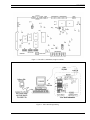
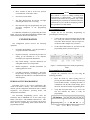
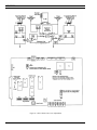
1
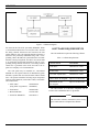
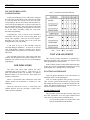
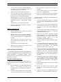
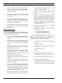
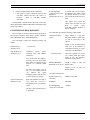
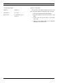
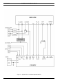
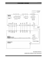
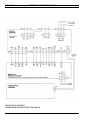
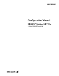
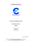
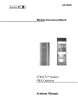
LBI-38986
EDACS®
CONVENTIONAL NETWORK INTERFACE (CNI)
GETC CONFIGURATION MANUAL
TABLE OF CONTENTS
SPECIFICATIONS* . . . . . . . . . . . . . . . . . . . . . . . . . . . . . . . . . . . . . . . . . . . . . . . . . . 3
SCOPE . . . . . . . . . . . . . . . . . . . . . . . . . . . . . . . . . . . . . . . . . . . . . . . . . . . . . . . . . 3
INTRODUCTION . . . . . . . . . . . . . . . . . . . . . . . . . . . . . . . . . . . . . . . . . . . . . . . . . . . 3
SOFTWARE REQUIREMENTS . . . . . . . . . . . . . . . . . . . . . . . . . . . . . . . . . . . . . . . . . . . 4
RELATED PUBLICATIONS . . . . . . . . . . . . . . . . . . . . . . . . . . . . . . . . . . . . . . . . . . . . . 5
OPERATION . . . . . . . . . . . . . . . . . . . . . . . . . . . . . . . . . . . . . . . . . . . . . . . . . . . . . 5
GENERAL . . . . . . . . . . . .
INTERFACE TO EDACS . . . .
CONSOLE PREEMPT . . . . .
CHANNEL GUARD MAPPING
.
.
.
.
.
.
.
.
.
.
.
.
.
.
.
.
.
.
.
.
.
.
.
.
.
.
.
.
.
.
.
.
.
.
.
.
.
.
.
.
.
.
.
.
.
.
.
.
.
.
.
.
.
.
.
.
.
.
.
.
.
.
.
.
.
.
.
.
.
.
.
.
.
.
.
.
.
.
.
.
.
.
.
.
.
.
.
.
.
.
.
.
.
.
.
.
.
.
.
.
.
.
.
.
.
.
.
.
.
.
.
.
.
.
.
.
.
.
.
.
.
.
.
.
.
.
.
.
.
.
.
.
.
.
.
.
.
.
.
.
.
.
.
.
.
.
.
.
.
.
.
.
.
.
.
.
.5
.5
.6
.6
MAPPING WITHOUT CHANNEL GUARD . . . . . . . . . . . . . . . . . . . . . . . . . . . . . . . . . 6
INSTALLATION . . . . . . . . . . . . . . .
EQUIPMENT REQUIRED . . . . . . .
HARDWARE INSTALLATION . . . .
Logic Board Modification . . .
Rockwell Modem Installation .
Turbo Board Installation . . . .
GETC Cable Modifications . .
Jumper Installation . . . . . . .
GETC FIRMWARE INSTALLATION .
EPROM Installation . . . . . .
TURBO SOFTWARE INSTALLATION
Preparation . . . . . . . . . . .
Programming Mode . . . . . .
Normal Mode . . . . . . . . .
.
.
.
.
.
.
.
.
.
.
.
.
.
.
.
.
.
.
.
.
.
.
.
.
.
.
.
.
.
.
.
.
.
.
.
.
.
.
.
.
.
.
.
.
.
.
.
.
.
.
.
.
.
.
.
.
.
.
.
.
.
.
.
.
.
.
.
.
.
.
.
.
.
.
.
.
.
.
.
.
.
.
.
.
.
.
.
.
.
.
.
.
.
.
.
.
.
.
.
.
.
.
.
.
.
.
.
.
.
.
.
.
.
.
.
.
.
.
.
.
.
.
.
.
.
.
.
.
.
.
.
.
.
.
.
.
.
.
.
.
.
.
.
.
.
.
.
.
.
.
.
.
.
.
.
.
.
.
.
.
.
.
.
.
.
.
.
.
.
.
.
.
.
.
.
.
.
.
.
.
.
.
.
.
.
.
.
.
.
.
.
.
.
.
.
.
.
.
.
.
.
.
.
.
.
.
.
.
.
.
.
.
.
.
.
.
.
.
.
.
.
.
.
.
.
.
.
.
.
.
.
.
.
.
.
.
.
.
.
.
.
.
.
.
.
.
.
.
.
.
.
.
.
.
.
.
.
.
.
.
.
.
.
.
.
.
.
.
.
.
.
.
.
.
.
.
.
.
.
.
.
.
.
.
.
.
.
.
.
.
.
.
.
.
.
.
.
.
.
.
.
.
.
.
.
.
.
.
.
.
.
.
.
.
.
.
.
.
.
.
.
.
.
.
.
.
.
.
.
.
.
.
.
.
.
.
.
.
.
.
.
.
.
.
.
.
.
.
.
.
.
.
.
.
.
.
.
.
.
.
.
.
.
.
.
.
.
.
.
.
.
.
.
.
.
.
.
.
.
.
.
.
.
.
.
.
.
.
.
.
.
.
.
.
.
.
.
.
.
.
.
.
.
.
.
.
.
.
.
.
.
.
.
.
.
.
.
.
.
.
.
.
.
.
.
.
.
.
.
.
.
.
.
.
.
.
.
.
.
.
.
.
.
.
.
.
.
.
.
.
.
.
.
.
.
.
.
.
.
.
.
.
.
.
.
.
.
.
.
.
.
.
.
.
.
.
.
.
.
.
.
.
.
.
.
.
.
.
.
.
.6
.7
.7
.7
.8
.9
. 10
. 11
. 11
. 11
. 11
. 12
. 12
. 12
CONFIGURATION . . . . . . . . . . . . . . . . . . . . . . . . . . . . . . . . . . . . . . . . . . . . . . . . . . 15
PERSONALITY PROGRAMMING . . . . . . . . . . . . . . . . . . . . . . . . . . . . . . . . . . . . . . 15
Programming Set-up . . . . . . . . . . . . . . . . . . . . . . . . . . . . . . . . . . . . . . . . . . 15
Programming the Personality . . . . . . . . . . . . . . . . . . . . . . . . . . . . . . . . . . . . . 15
REPEATER PERSONALITY . . . . . . . . . . . . . . . . . . . . . . . . . . . . . . . . . . . . . . . . . . 17
DIP SWITCH SETTINGS . . . . . . . . . . . . . . . . . . . . . . . . . . . . . . . . . . . . . . . . . . . . 17
MODEM ALIGNMENT . . . . . . . . . . . . . . . . . . . . . . . . . . . . . . . . . . . . . . . . . . . . 17
CEC/IMC PERSONALITY CONFIGURATION . . . . . . . . . . . . . . . . . . . . . . . . . . . . . . . . 20
ERICSSONZ
LBI-38986
TABLE OF CONTENTS - Cont.
LED INDICATORS . . . . . . . . . . . . . . . . . . . . . . . . . . . . . . . . . . . . . . . . . . . . . . . . . . 20
TEST AND ALIGNMENT . . . . . . . . .
FUNCTIONAL CHECKOUT . . . .
Locally Initiated Call . . . .
Multisite Initiated Call . . . .
REPEATER ADJUSTMENTS . . . .
MASTR II and IIe Repeaters
MASTR IIIRepeaters . . . .
.
.
.
.
.
.
.
.
.
.
.
.
.
.
.
.
.
.
.
.
.
.
.
.
.
.
.
.
.
.
.
.
.
.
.
.
.
.
.
.
.
.
.
.
.
.
.
.
.
.
.
.
.
.
.
.
.
.
.
.
.
.
.
.
.
.
.
.
.
.
.
.
.
.
.
.
.
.
.
.
.
.
.
.
.
.
.
.
.
.
.
.
.
.
.
.
.
.
.
.
.
.
.
.
.
.
.
.
.
.
.
.
.
.
.
.
.
.
.
.
.
.
.
.
.
.
.
.
.
.
.
.
.
.
.
.
.
.
.
.
.
.
.
.
.
.
.
.
.
.
.
.
.
.
.
.
.
.
.
.
.
.
.
.
.
.
.
.
.
.
.
.
.
.
.
.
.
.
.
.
.
.
.
.
.
.
.
.
.
.
.
.
.
.
.
.
.
.
.
.
.
.
.
.
.
.
.
.
.
.
.
.
.
.
.
.
.
.
.
.
.
.
.
.
.
.
.
.
.
.
.
.
.
.
.
.
.
.
.
.
.
.
.
.
.
.
.
.
.
.
.
.
.
.
.
.
.
.
.
20
20
20
21
21
21
22
TROUBLESHOOTING . . . . . . . . . . . . . . . . . . . . . . . . . . . . . . . . . . . . . . . . . . . . . . . . 22
CNI INTERFACE REQUIREMENTS . . . . . . . . . . . . . . . . . . . . . . . . . . . . . . . . . . . . . . . . 23
INTERCONNECT DIAGRAMS . . . . . . . . . . . . . . . . . . . . . . . . . . . . . . . . . . . . . . . . . . . 27
INSTALLATION DIAGRAMS . . . . . . . . . . . . . . . . . . . . . . . . . . . . . . . . . . . . . . . . . . . . 29
FIGURES and TABLES
Figure 1- CNI Block Diagram . . . . . . . . . . . . . . . . . . . . . . . . . . . . . . . . . . . . . . . . . . . . 4
Figure 2 - DataCommunication . . . . . . . . . . . . . . . . . . . . . . . . . . . . . . . . . . . . . . . . . . . . 6
Figure 3 - Logic Board (19D904266) Modification . . . . . . . . . . . . . . . . . . . . . . . . . . . . . . . . . 8
Figure 4 - Simplified Diagram of Modified Circuit . . . . . . . . . . . . . . . . . . . . . . . . . . . . . . . . . 8
Figure 5 - GETC Shelf (Rear View) . . . . . . . . . . . . . . . . . . . . . . . . . . . . . . . . . . . . . . . . . 10
Figure 6 - Simplified Diagram of Modified Harness . . . . . . . . . . . . . . . . . . . . . . . . . . . . . . . . . 11
Figure 7 - CNI GETC(19D904266) Jumper Locations . . . . . . . . . . . . . . . . . . . . . . . . . . . . . . . . 13
Figure 8 - Turbo Board Programming . . . . . . . . . . . . . . . . . . . . . . . . . . . . . . . . . . . . . . . . 13
Figure 9 - Switch Settings for Personality Programming Mode . . . . . . . . . . . . . . . . . . . . . . . . . . . 15
Figure 10 - Personality Programming . . . . . . . . . . . . . . . . . . . . . . . . . . . . . . . . . . . . . . . . . 16
Figure 11 - CNI GETC Switch Settings . . . . . . . . . . . . . . . . . . . . . . . . . . . . . . . . . . . . . . . 17
Figure 12 - GETCPhone Line Level Adjustments . . . . . . . . . . . . . . . . . . . . . . . . . . . . . . . . . . 18
Figure 13 - Sample CNI Personality . . . . . . . . . . . . . . . . . . . . . . . . . . . . . . . . . . . . . . . . . 19
Figure 14 - CNI Troubleshooting Chart . . . . . . . . . . . . . . . . . . . . . . . . . . . . . . . . . . . . . . . . 25
Figure 15 - Typical CNI to Conventional Repeater Interface . . . . . . . . . . . . . . . . . . . . . . . . . . . . . 26
Table 1 - Software Requirements . . . . . . . . . . . . . . . . . . . . . . . . . . . . . . . . . . . . . . . . . . . 4
Table 2 - Jumper Settings . . . . . . . . . . . . . . . . . . . . . . . . . . . . . . . . . . . . . . . . . . . . . . . 14
Table 3 -Front Panel LED State Indicators . . . . . . . . . . . . . . . . . . . . . . . . . . . . . . . . . . . . . . 20
This manual is published by Ericsson Inc., without any warranty. Improvements and changes to this manual necessitated by typographical
errors, inaccuracies of current information, or improvements to programs and/or equipment, may be made by Ericsson Inc., at any time and
without notice. Such changes will be incorporated into new editions of this manual. No part of this manual may be reproduced or transmitted
in any form or by any means, electronic or mechanical, including photocopying and recording, for any purpose, without the express written
permission of Ericsson Inc.
Copyright® October 1994, Ericsson GE Mobile Communications Inc.
2
LBI-38986
SPECIFICATIONS*
Input Voltage
+13.8 Vdc •20%
Current Drain with 9600 Baud Modem
1.5 Amp (typ), 2.0 Amp (max.)
Operating Temperature
-22°F to +140°F
(-30°C to +60°C)
Dimensions (H x W)
1.75 x 19 inches (EIA rack mount)
(4.5 x 48.3 cm)
Repeater Compatibility
MASTR II or IIe, all frequency bands
MASTR III, all frequency bands
Network Interface: 2 & 4 wire circuits
(audio and data) Bell Std 3002 grade
Data Rate
Transmit Level
Receive Level
9600 Baud
0.77 Volts rms (0 dBm)
0.16 Volts rms on J3A-32 of GETC Logic Board
Repeater Audio
Transmit Level
Receive Level
0 dBm, 0 Vdc offset
0 dBm, 0 Vdc offset
Channel Access
500 to 750 ms (IMC site)
Valid Channel Guard Tones (Hz)
67.0, 71.9, 74.4, 77.0, 79.7,
82.5, 85.4, 88.5, 91.5, 94.8,
100.0, 103.5, 107.2, 110.9, 114.8,
118.8, 123.0, 127.3, 131.8, 136.5,
141.3, 146.2, 151.4, 156.7, 162.2,
167.9, 173.8, 179.9, 186.2, 192.8
CNI Group/Channel Guard Pair
4
* These specifications are intended primarily for the use of the service technician. Refer to the appropriate
Specification Sheet for the complete specifications.
SCOPE
INTRODUCTION
The Conventional Network Interface (CNI) provides the
communication link between a conventional repeater
(MASTR II, IIe, or III) and an Enhanced Digital Access
Communication System (EDACS). This communication
link is provided by modifying the Ericsson GE Trunking
Card (GETC) which interfaces with the Console Electronics
Controller (CEC) or Integrated Multisite and Console
(IMC) Controller. This manual explains the CNI operation
and the steps necessary to reconfigure and program the
GETC for CNI operation.
The CNI station equipment is part of a wide area network that is interfaced to a CEC/IMC through an Uplink
configured GETC. Figure 1 shows the CNI and Uplink
connection which is implemented using a four-wire, data
grade, type 3002 audio (telephone) line. The audio connection between the CEC/IMC and the repeater is also a fourwire audio (telephone) line.
The CNI GETC converts analog Channel Guard tones
into EDACS Group ID’s (GID) based on mapping informa-
3
LBI-38986
Figure 1 - CNI Block Diagram
tion stored in the CNI GETC personality EEPROM. When
a conventional transmission is received, the GETC decodes
the analog Channel Guard tones and associates the tone
with an EDACS GID. The inbound Channel Guard tone is
defined in the personality EEPROM along with a corresponding GID in the EDACS System.When the CEC/IMC
transmits a Group Assignment, the GETC converts the GID
to an outbound conventional transmission with its corresponding analog Channel Guard tone. The analog Channel
Guard tone is generated in the GETC and sent to the repeater to accompany voice for transmission.
The CNI option may be installed in a conventional
MASTR II or IIe (option STCP3Z) or MASTR III (option
SXCP5T) repeater that uses EIA RS-220A Channel Guard
tones. The options include the following major components
with associated hardware, interconnect cables, and modification instructions:
• GETC Shelf
(using GETC Logic Board
19D901868G3
19D904266)
• Turbo Board
19D903536P1
• Rockwell Modem
19A705178P1
• CNI GETC PROM Kit
344A3497G1
SOFTWARE REQUIREMENTS
The CNI installation requires the following software:
Table 1 - Software Requirements
APPLICATION
SOFTWARE
CNI GETC
344A3497G1 or later
Turbo board
344A4414G1 or later
CEC/IMC Uplink GETC
344A4895G1 or later
GETC Shelf - PC Program
TQ-3357 V3.00 or later
MASTR II, IIe, III
PC Program
TQ-3357 V9.00 or later
The CNI software is, to this date, compatible with all
versions of the 19D904266 GETC Logic Board.
NOTE
The CNI GETC software, 344A3497G1, does not support Control Stations or Simplex Base Stations.
4
LBI-38986
OPERATION
NOTE
This software is subject to change resulting from improvements or enhancements. When upgrading the
softwaare, refer to the accompanying software release
notes for software compatibility information.
RELATED PUBLICATIONS
It may be necessary to consult one or more of the
following documents during the installation process. These
manuals will also provide additional guidance if you
encounter technical difficulties during the configuration
process.
LBI-33031
- Rockwell Modem Model R96FT
(19A705178) Maintenance Manual
LBI-38430
- MASTR II, IIe Control Shelf
Maintenance Manual
LBI-38636
- MASTR III Installation Manual
LBI-38662
- IMC Maintenance Manual
LBI-38822
- Turbo Board (GETC 1e) Maintenance
Manual
LBI-38894
- GETC Trunking Card Maintenance
Manual
LBI-38896
- EDACS Site Downlink and CEC/IMC
Uplink Configuration Manual
LBI-38984
- EDACS System Manager User’s Guide
LBI-38988
- EDACS Station GETC Configuration
Manual
LBI-39024
- CEC/IMC Manager (MOM), Version
3.xx Operations Guide.
SRN-1008
- Software Release Notes for GETC CNI
Software
SRN-1010
- Software Release Notes for Turbo
Board Software
SRN-1061
- Software Release Notes for Link GETC
Software
TQ-3353
- MASTR II, IIe, and III PC Programming
Manual
TQ-3357
- GETC Shelf Programming Manual
GENERAL
The CNI GETC performs two basic operations. First, it
converts the Channel Guard tone information in a
conventional transmission to an EDACS compatible Group
Call Assignment message. It then functions as a Downlink
GETC and transfers the EDACS message to the CEC/IMC’s
Uplink GETC.
Second, the CNI GETC functions as a Downlink GETC
when receiving an EDACS message from the CEC/IMC’s
Uplink GETC. For example, the CNI GETC receives an
EDACS message representing a Group Channel Request. It
then converts the EDACS message to a conventional
transmission including the appropriate Channel Guard tone
information using Carrier Activated Squelch (CAS) only.
The CNI GETC performs the conversions between
Channel Guard and EDACS Group ID’s based on
information stored in the CNI GETC’s personality. It is also
possible to convert a single EDACS group to a conventional
transmission without Channel Guard tone.
INTERFACE TO EDACS
The CNI GETC provides the control and conversion
functions necessary to implement EDACS access to the
conventional service area. In addition to performing
conversions between Channel Guard and EDACS formats,
the CNI GETC acts as a message conduit providing a data
communication path between the CNI GETC and the
CEC/IMC. The CNI GETC supports any Channel Guard
Frequency defined in EIA RS-220A between 67.0 Hz and
192.8 Hz (see Specification data for a listing of supported
frequencies).
The CNI GETC decodes Channel Guard information
when receiving a conventional transmission. If the Channel
Guard information matches with the data in the CNI
GETC’s Personality, a Group Call Assignment Message
goes to the CEC/IMC’s Uplink GETC. The CNI GETC
also regenerates the Channel Guard tone information for use
by the CNI GETC’s repeater.
The CNI GETC’s phone modem data is synchronous at
9600 baud using the full duplex operating mode. Data
flows simultaneously in both directions as illustrated in
Figure 2.
5
LBI-38986
CHANNEL GUARD MAPPING
The CNI GETC performs conversions between Channel
Guard tones and EDACS IDs based on mapping
information within the CNI GETC’s Personality.
Personality refers to the GETC’s region of memory that
stores configuration data.
Figure 2 - Data Communication
The CNI GETC also performs data error detection and
correction, general control of timer and I/O functions (DIP
switch, LED’s, UART’s, etc.), receive and transmit buffer
management, message scheduling, and Turbo Board
interfacing.
When the CNI GETC receives a Group Channel
Request Message from the CEC/IMC’s Uplink, the CNI
GETC compares the Group ID with configuration data in
the CNI GETC’s Personality. If the Group ID is valid, the
CNI GETC sends a secondary assignment to the
CEC/IMC’s Uplink and simultaneously keys the base
station using the appropriate Channel Guard information.
The personality data in Figure 13 shows an example of
the mapping information used to convert between the
Channel Guard tones and EDACS Group ID’s. The bottom
two lines of Figure 13 show a 67.0 Hz Channel Guard tone
maps to a Network Group ID of 271. Mapping provides a
maximum of four EDACS Network Groups for each CNI
GETC.
MAPPING WITHOUT CHANNEL GUARD
In addition to standard mapping, it is also possible to
map one EDACS group to a conventional transmission
without any Channel Guard tone information using the CAS
signal. This flexibility permits conventional radios, without
Channel Guard, access to the advanced trunking features of
EDACS. In this case, mapping provides one EDACS
Network Group per CNI GETC.
INSTALLATION
CONSOLE PREEMPT
Since the CNI GETC operates as a one channel site,
only one conversation may occur at any time. The CNI
GETC ignores additional conventional transmissions with
the same Channel Guard information and Multisite Group
Call Requests. However, when the Console preempts the
current call, the CNI GETC will route audio from the
Console to the receiving conventional radio. The original
radio’s unkey does not drop the call as long as the console is
still keyed. The Console’s unkey will drop the call
regardless of the original radio’s status.
A different situation occurs when the CNI GETC is
processing one conventional transmission and is interrupted
with another conventional transmission with different
Channel Guard tone information. The additional call will
most likely interfere with the current call.
The installation process involves the following steps and
should be completed in the order presented:
NOTE
CNI GETC’S ordered from the factory have already
been modified and set up for CNI operation using the
latest software. Use these installation procedures for
field conversion of a standard GETC to a CNI GETC
or to upgrade firmware or software.
1.
Hardware Installation - This procedure provides
instructions for converting a standard GETC to a
CNI GETC in the field. The instructions include
hardware installation, instructions for modifying
existing cables, and installation of GETC jumpers.
2.
GETC Firmware Installation - This procedure
provides instructions for installing the GETC
operating firmware.
3.
Turbo Software Installation - This procedure
provides instructions for installing the Turbo Board
software.
NOTE
To prevent overlapping conventional transmissions, all
of the conventional radios should be programmed with
the Transmit Busy Lockout feature.
6
LBI-38986
EQUIPMENT REQUIRED
1.
Place the GETC shelf in the service position.
The following equipment and software may be required
to modify and configure the CNI GETC:
2.
Disconnect all cables from the GETC Logic Board.
3.
Remove the GETC Logic Board 19D904266 from
the shelf. Refer to the GETC Service Manual LBI38894 for detailed instructions for removing and
installing the printed circuit board in the GETC
shelf.
4.
Solder an orange wire jumper 19A115663P4 (part
of Hardware Kit 344A4019) from TP107 to J7-7.
Route the wire as shown in Figure 4. This allows
access to the test point which will be covered by
the Turbo Board installation.
IBM compatible PC with at least 640K memory,
monitor, and keyboard.
• Hard disk is recommended; but, not required.
• Serial Port configured as either COM1 or COM2.
• TQ-3360 programming cable.
• Male DB-25 to female DB-9 adapter.
• Software distribution diskette 344A4414.
• Oscilloscope.
• Standard hard tools.
• Temperature controlled soldering station.
HARDWARE INSTALLATION
Typically, a CNI GETC is installed in the repeater
cabinet, just above the repeater’s radio assembly, using
hardware kit 19A130031G30. The tray containing the subassemblies is mounted within a slide out shelf measuring
1.75 inches high (one rack unit) by 19 inches wide.
Install the GETC Shelf into the repeater cabinet, refer to
the MASTR II, IIe, or MASTR III Application Assembly
and Installation Diagrams for detailed information on
installing the GETC Shelf. Installation or removal of the
shelf sub-assemblies involves sliding the GETC tray out of
the cabinet and into the service position. This position
allows access to the shelf’s sub-assemblies.
Observe basic safety precautions to prevent injury or
equipment damage.
CAUTION
Observe precautions
for handling
ELECTROSTATIC
SENSITIVE DEVICES
Logic Board Modification
The following steps provide instructions for modifying
the GETC Logic Board. Materials for this modification are
provided in Hardware Kits 344A3845 and 344A4019. For
additional GETC assembly and maintenance information,
refer to LBI-38894 and LBI-38988.
NOTE
Do Not install the jumper wire between TP107 and J77 when the CNI GETC is used in MASTR III
repeaters. If the wire was previously installed,
disconnect it from J7-7.
5.
Solder the white wire 19A115871P22 (part of
Hardware Kit 344A3845) between TP102 and J182 as shown in Figure 4. This essentially connects
the output of the Low Speed Decode Filter to U1’s
interrupt line, INT0 as shown in Figure 3.
6.
Reinstall the Logic Board into the GETC Shelf
using the installation instructions provided in LBI38894. Omit the three (3) screws on the J3 end of
the board (these will be used to secure the Turbo
Board).
The modified circuit functions as follows:
The conventional received audio (VOL/SQ HI) enters
the GETC at J7-2. This audio includes sub-audible signals
that represents the Channel Guard tone information. The
Low Speed Decode Filter removes the received audio and
routes the Channel Guard tone information to U1, the
GETC’s main processor.
The standard parallel input at U1-3 is unused in the CNI
configuration. Instead, U1 processes the Channel Guard
tone information using the interrupt line at U1-12. The CNI
application also requires a jumper from J18 pin 1 to pin 2.
The CNI uses the signal at INT0 to convert a
conventional transmission with Channel Guard tone
information into a digital EDACS message representing
Group Call Assignments. This process results in the
CEC/IMC seeing a normal EDACS Group Call channel
assignment message based on the sub-audible Channel
Guard tone information embedded in a conventional
transmission.
7
LBI-38986
Figure 4 - Logic Board (19D904266) Modification
Rockwell Modem Installation
The Rockwell Modem provides a high speed
synchronous serial interface between the CNI GETC and
the CEC/IMC’s Uplink. The CNI GETC uses the modem to
send and receive serial digital data representing GID
information, polling messages, keying messages, and
channel assignments. Data transfer rates are typically 9600
bits per second (bps) using 3002 grade four-wire audio
lines. Additional information on installing and testing the
modem may be found in LBI-33031, LBI-38894, and LBI38822.
Install the Rockwell Modem using the following
procedure:
1.
Figure 3 - Simplified Diagram of Modified Circuit
8
Insert the Rockwell Modem into J3 on the GETC
Board and align the mounting holes over the
GETC shelf standoffs.
LBI-38986
2.
Isolate the modem from the shelf by installing the
eight (8) fiber washers (4035306P25, part of
Hardware Kit 344A4019). Insert four (4) washers
between the modem and the shelf standoffs and
place the other four (4) washers on top of the
modem board over the mounting holes.
3.
Install three (3) threaded spacers 19B201955P9 in
place of the screws omitted when Logic Board was
reinstalled.
4.
Install two (2) threaded spacers 19B201955P9
through the modem and into the shelf standoffs
next to J3.
5.
Align the Turbo Board holes over the threaded
spacers installed in steps 3 and 4 (orient the Turbo
Board so connectors J2 and J3 are toward the rear
of the GETC Shelf).
6.
Secure the Turbo Board by installing two (2) pan
head screws N80P13004B6 and two (2) lock
washers N404P13B6 through the board and into
the threaded spacers located near the front of the
GETC Shelf (near S1 and Y1).
7.
Install three threaded spacers 19B201955P9
through the Turbo Board into the remaining
spacers. These will be used to mount the guard.
8.
Install the guard 19B802166P1 using three (3) flat
head screws N404P13B6. The guard protects the
Turbo Board from inadvertent damage when
sliding the GETC Shelf in and out of the service
position.
The Turbo Board uses mostly surface mounted
components and mounts on stand offs above the GETC
Logic Board. Electrical connections are made through a 28
conductor ribbon cable on the Turbo Board to the XU3
socket on the GETC Logic Board. Installation of a small
mechanical shield above the Turbo Board protects it from
inadvertent damage when sliding the GETC drawer in and
out of the cabinet. Additional information on the Turbo
Board assembly and maintenance instructions for the board
may be found in LBI-38822.
9.
Plug the ribbon cable from J1 on the Turbo Board
into the XU3 socket on the GETC Logic Board.
Use the following procedures to install the Turbo Board.
Mounting hardware for the Turbo Board is contained in
Hardware Kit 344A4019.
12. Secure the harness to the GETC shelf using
retaining strap 19J706152P5.
NOTE
The modem must be insulated from the shelf mounting
standoffs using eight washers. Four washers mount on
top of the modem’s printed circuit board and four
washers mount on the bottom of the modem’s printed
circuit board.
3.
Secure the modem by installing two screws (left
over from the Logic Board installation) through the
washers and modem board into the standoffs
located on the end opposite J3.
Turbo Board Installation
The Turbo Board provides the CNI with additional
memory and processing capability through dual 8051 based
processors and support circuitry. It primarily provides
additional processing power. However, it also provides real
time debug capability during development, testing, and
troubleshooting.
1.
Remove U3 (19A705558P1) from the XU3 socket
on the GETC Logic Board. Observe precautions
for handling electrostatic sensitive devices
2.
Bend over or slightly move any components on the
Logic Board whose height will interfere with the
Turbo Board installation.
10. Install the harness assembly, 19C337712G1, by
sliding the P2/P3 end of the harness through the
hole provided into the back of the GETC shelf.
11. Connect the 19C337712G1 Harness P2 and P3 to
the J2 and J3 Turbo Board connectors,
respectively.
13. Mount the other end of the harness on the rear of
the GETC Shelf. Secure the J103/J104 support
bracket to the shelf using the two (2) nut clips
7160861P33
and
self
tapping
screws
19A134011P1 included with the harness.
When the installation is complete, examine the GETC
Shelf for any loose hardware. You may now proceed to
modify and reconnect the GETC cables.
9
LBI-38986
GETC Cable Modifications
Use the following procedures to modify and reconnect
cables in the CNI GETC. Be sure to follow the correct
procedures. Instructions titled MASTR II or IIe are for CNI
GETC’s installed in MASTR II or MASTR IIe repeaters,
instructions titled MASTR III are for CNI GETC’s installed
in MASTR III repeaters only.
NOTE
Modification of the GETC for use with MASTR II
(IIe) and MASTR III repeaters differ. Use the
procedure applicable to the type of repeater associated
with the CNI GETC.
MASTR II & IIe
The following procedure provides instructions for
modifying the cables when the CNI GETC (option
STCP3Z) is used with a MASTR II or IIe repeater.
Materials for the modification are provided as part of the
Hardware Kit 344A3845G1.
1.
2.
3.
Mount the Terminal block, 19C301087P10, on the
back of the GETC Shelf using the four (4) screws,
N80P13007B6, and two (2) nuts, 7160508P2
provided. Refer to Figure 5.
Disconnect the two (2) pairs of twisted wire
connected to P26-6, P26-7, P26 8 and P26-9 (part
of cable harness 19C320811G15/G16) from the
Backplane (19D417214) TB1201-18, -17, 11, and
10 or from the Control Panel (19B234871) or MIIe
Backplane (19D902459) TB1201-5, -2, -3, and -4
respectively.
Connect the pair from P26-8 and P26-9 to the
terminal block terminals 1 and 2 respectively. This
is the GETC Transmit Data pair, see Figure 6.
4. Connect the pair from P26-6 and P26-7 to the
terminal block terminals 3 and 4 respectively. This is the
GETC Receive Data pair.
NOTE
On MASTR IIe stations only, using wire harness
19C320811G16.
Cut the solid white jumpers
connected from P27-14 to P27-15 and from P27-6 to
P27-16.
5.
Connect the harness assembly (19C320811) plug
P26 to the GETC Logic Board connector J6.
6.
Connect the harness assembly (19C320811) plug
P27 to the GETC Logic Board connector J7.
7.
Connect the harness assembly (19C320811) plug
P10 to the GETC Logic Board connector J10.
8.
Connect the harness assembly (19C336863) plug
P8 to the GETC Logic Board connector J8.
9.
Connect the harness assembly (part of 19C320811
and 19C336863) plug P19 to the GETC Logic
Board connector J19.
10. Connect the Regulator Board harness assembly
(A2W1) plug P1 to the GETC Logic Board
connector J27.
MASTR III
The following procedure provides instructions for
modifying the cables when the CNI GETC is used with a
MASTR III repeater. Materials for the modification are
provided as part of the MIII option SXCP5T.
1.
Route the header (P26) on the Harness
19C337792P1 through the terminal block hole and
mount the terminal block to the back of the GETC
Shelf using the four (4) screws, N80P13007B6,
and two (2) nuts, 7160508P2 provided. Refer to
Figure 5.
Figure 5 - GETC Shelf (Rear View)
10
LBI-38986
2.
Remove the contacts (4) from the header (P26) on
the harness 19C337792P1.
GETC FIRMWARE INSTALLATION
3.
Remove contacts from 19B802401P1, P6-8 and
P6-9. This is the GETC Transmit Data pair, see
Figure 6.
The firmware installation procedure involves installing
the latest version of the CNI EPROM (344A3497) into the
CNI GETC.
4.
Remove contacts from 19B802401P1, P6-6 and
P6-7. This is the GETC Receive Data pair.
5.
Connect the harness assembly (19B802401P1)
plug P6 to the GETC Logic Board connector J6.
6.
Connect the harness assembly (19B802401P1)
plug P7 to the GETC Logic Board connector J7.
NOTE
This software is subject to change resulting from
improvements or enhancements. When upgrading the
software, the procedures provided in the
accompanying software release notes takes precedence
over this manual.
7.
Connect the harness assembly (19B802401P1)
plug P10 to the GETC Logic Board connector J10.
8.
Connect the harness assembly (19C336863) plug
P8 to the GETC Logic Board connector J8.
9.
Connect the harness assembly (part of
19B802401P1 and 19C336863) plug P19 to the
GETC Logic Board connector J19.
10. Connect the Regulator Board harness assembly
(A2W1) plug P1 to the GETC Logic Board
connector J27.
Jumper Installation
There are a few jumpers on the GETC Logic Board
which must be re-configured for CNI operation. To
properly configure the jumpers, refer to Table 2 and install
or remove jumpers according to table. The location of the
jumpers may be found using the board layout diagram in
Figure 7 or by referring to the full scale GETC Diagrams in
LBI-38988.
CAUTION
Observe precautions
for handling
ELECTROSTATIC
SENSITIVE DEVICES
EPROM Installation
Perform the following steps to install the CNI GETC
firmware:
1.
Remove power from the GETC and place the
GETC shelf in the service position. This will
allow access to the EPROM.
2.
Remove the GETC EPROM U2.
3.
Install the CNI EPROM into the XU2 socket
(ensure the EPROM’s pin 1 is properly aligned
with pin 1 on the socket, see Figure 4).
4.
Proceed to the Software Installation procedure.
TURBO SOFTWARE INSTALLATION
The two Turbo Board processors communicate with
each other through a parallel bus. Communication with the
main GETC processor is through the 8K dual port RAM
bank comprised of U3 and U4. In addition, each turbo
processor has an RS-232 serial port used for Turbo
Programming.
Figure 6 - Simplified Diagram of Modified Harness
CNI stations built in the factory come with the latest
software. To upgrade an existing station, refer to the
software release notes for the appropriate version of the
Turbo Board software. It will vary with the version of
GETC Logic Board software. Group 1 of the CNI software,
344A3497G1, is compatible with Group 1 of the Turbo
Board software, 344A4414G1.
11
LBI-38986
This procedure provides instructions for programming
the Turbo Board installed in the CNI GETC. The
installation process uses the software diskette 344A4414, an
IBM compatible personal computer (PC), and an
interconnecting cable (TQ-3360).
The PC reads data from the files on the 344A4414
diskette and transfers the data to the Turbo Board
microprocessor through connectors J103 and J104 at the
rear of the GETC Shelf.
Running the "load1e.exe" executable program serially
moves data from the "1etop.hex" and "1ebot.hex" files to
the code segment of the Turbo Board’s memory.
The "1ecrc.hex" file provides Cyclical Redundancy
Check (CRC) information for use in error checking and
verification during the file transfer or "programming"
process. Any errors encountered during this procedure
generally indicate a defective communication link between
the PC and Turbo Board.
NOTE
If an error occurs, check connectors and cables. Cycle
S2 and S3 from the front position, to the rear position,
and again to the front position. If the PC continues to
indicate an error, refer to the Turbo Board
Maintenance Manual LBI-38822.
4.
Move the Turbo Board run/load switches S2 and
S3 to the load position (toward the front of the
GETC shelf). The front position of S2 and S3
places the processors U1 and U2 into the
programming mode. If either switch is already
toward the front, move the switch to the rear and
then back to the front position.
5.
The Turbo Board LEDs D1 and D2 should turn
OFF indicating that the Turbo Board is in the
programming mode.
Programming Mode
This procedure downloads the Turbo Board software to
the microprocessors U1 and U2 on the Turbo board.
NOTE
Re-programming the GETC Turbo Board will not alter
previously stored Personality Data. When Personality
Data is present, "load1e.exe" clears and performs CRC
functions over the code portion of memory only.
1.
The "load1e.exe" program loads the file
"1etop.hex" into the Turbo Board’s upper half of
memory for use by the top processor U1.
Preparation
Prepare the PC for programming the CNI GETC Turbo
Board by performing the following steps:
1.
Connect the TQ-3360 programming cable from the
PC’s serial port connector to the GETC Shelf
connector J104 (see Figure 8). (A DB-25 to DB-9
adapter may be needed.)
2.
Using standard DOS commands or a software file
manager, create a directory named "LOAD1E" on
the PC’s hard drive.
3.
Make "LOAD1E" the current default directory and
copy the following files from the software diskette
into the "LOAD1E" directory:
• load1e.exe
• 1etop.hex
• 1ecrc.hex
• 1ebot.hex
12
Execute the "load1e.exe" program on the PC and
follow the on screen instructions.
2.
Monitor the PC’s on screen instructions and
prompts.
3.
When directed, move the TQ-3360 programming
cable from the GETC Shelf J104 to J103.
4.
The PC will indicate it is loading the "1ebot.hex"
file into the Turbo Board’s lower half of memory
for use by the bottom processor U2.
Normal Mode
Upon successful completion of the programming mode,
the PC displays a "FINISHED" message. It will also
provide instructions to switch S2 and S3 to the rear position
for normal operation.
LBI-38986
Figure 7 - CNI GETC (19D904266) Jumper Locations
Figure 8 - Turbo Board Programming
13
LBI-38986
Table 2 - Jumper Settings
Jumper setting for CNI GETC (19D904266 ONLY).
Jumper
Position
P11
P12
P13
P14
Wideband
CNI
GETC
1&2
1&2
1&2
1&2
Narrow band
CNI
GETC
1&2
1&2
1&2
1&2
P15
P16
1&2
1&2
1&2
1&2
P17
P18
P20
P21
P24
P25
P26
P28
P29
P44
P46
1&2
1&2
OMIT
1&2
1&2
1&2
1&2
1&2
1&2
1&2
1&2
1&2
1&2
OMIT
1&2
1&2
1&2
1&2
1&2
1&2
1&2
1&2
P47
P48
P50
P51
P52
P53
P54
P55
P60
P61
P62
1&2
1&2
1&2
OMIT
2&3
1&2
1&2
OMIT
1&2
2&3
1&2
1&2
1&2
1&2
OMIT
2&3
1&2
1&2
OMIT
1&2
2&3
2&3
P63
P64
OMIT
OMIT
1&2
1&2
P65
P66
P67
OMIT
OMIT
OMIT
1&2
1&2
OMIT
1 & 2 for 4800 baud (900 MHz Narrow band)
1 & 2 for 4800 baud (900 MHz Narrow band)
P68
P69
1&2
OMIT
1&2
OMIT
Selects Local (on)/Remote (off) control of station PTT.
P71
P72
P73
1&2
1&2
2&3
1&2
1&2
2&3
Enables phone modem RTS control.
Selects internal oscillator.
Enables NOR gate U22B for EDACS applications.
P74
2&3
2&3
CAS polarity normal.
Legend:
14
LSD = Low Speed Data
HSD = High Speed Data
FUNCTION
Enables Receive Data from 9600 baud modem board.
Enables Clear-To-Send (CTS) from 9600 baud modem board.
BSL Tx output to BSL Rx input.
Master site controller path selection enable.
Backup site controller path selection enable.
BSL selection enable.
LSD encode path enable.
LSD decode path enable.
Enable high-speed data acquisition rate control, HSACQ.
BSL selection (Failsoft) enable.
LSD encode path enable.
Lock-detect path enable.
Sync line input path enable.
Enable site controller RxD, J8-4.
Use for 256K or 512K EPROM.
Used for normal communications.
BSL select.
BSL select.
Enable tone control for voted system
TxD polarity invert.
RxD polarity normal.
Enable MODCNTL local control.
Enables HSD path.
Use for 512K EPROM.
1 & 2 selects 11.0592 MHz clock Freq. for 9600 baud data (Wideband).
2 & 3 selects 5.5296 MHz clock freq. for 4800 baud data (Narrow band).
1 & 2 for 4800 baud (900 MHz Narrow band)
1 & 2 for 4800 baud (900 MHz Narrow band)
BSL = Backup Serial Link
MSL = Main Serial Link
RxD = Receive Data
TxD = Transmit Data
LBI-38986
1.
Move switches S2 and S3 to the "run" position
(toward the back of the GETC shelf).
2.
Press S4 to reset the GETC.
3.
The Turbo Board LEDs, D1 and D2, will light
indicating the station code is executing.
4.
Disconnect the TQ-3360 programming cable upon
successful completion of the programming
procedure.
For additional information on programming the Turbo
Board, refer to the Turbo Board Maintenance Manual LBI38822 and Software Release Note SRN-1062.
CONFIGURATION
The configuration process involves the following
operations:
1.
Personality Programming - Use this procedure to
set up the CNI GETC Personality.
2.
Repeater Personality - Describes the procedure for
setting up the MASTR III or IIe Repeater
Personality (not required for MASTR II).
3.
Dip Switch Settings - Provides instructions for
setting DIP switches for CNI operation.
4.
Modem Alignment - Provides Instructions for
adjusting phone line levels.
5.
CEC/IMC Personality Configuration - Describes
the procedures necessary for setting up the System
Manager and CEC/IMC for Conventional Network
and Group ID’s.
NOTE
This software is subject to change resulting from
improvements or enhancements. The instructions
contained in this manual are for guidance only. When
programming the personality, the detailed instructions
contained in TQ-3357 and the accompanying software
takes precedence over this manual.
Programming Set-up
Prepare the PC for Personality Programming by
performing the following steps:
1.
Connect the TQ-3360 programming cable from the
PC’s serial port connector (COM1/COM2) to the
CNI GETC Shelf connector J100 (see Figure 10).
(A DB-25 to DB-9 adapter may be needed.)
2.
Set the GETC DIP switches S1, S2, and S3 for the
programming mode as shown in Figure 9.
Figure 9 - Switch Settings for Personality Programming
Mode
Programming the Personality
Program the personality into the CNI using the
following procedures:
1.
Reset the GETC by either cycling power or
pressing the GETC RESET switch S4, located just
below the DIP switches. Resetting the GETC, in
combination with the DIP switch settings, places
the GETC into the Personality Programming mode.
2.
Verify that front panel LEDs L3, L4, and L5 are
ON, this indicates the GETC is ready for
programming.
PERSONALITY PROGRAMMING
Personality refers to the system configuration data
stored in the GETC’s memory. The GETC’s Personality
includes system configuration information such as channel
frequencies, call parameters, operating modes, and
identification information.
The Personality Programming process stores the
Personality data in EEPROM U35 on the GETC Logic
Board (CNI GETC’s with EPROM 344A3497G1). This
process involves using the TQ-3357 (Version 3.00 or later)
GETC Shelf PC programming Guide which includes the
programming software.
15
LBI-38986
3.
Following the instructions in TQ-3357, select the
"GE" directory and execute the "GTC" command.
After a brief introductory screen, the Current
Personalities Screen appears.
The programming software offers menu selections and
function keys for comprehensive GETC Personality
management including:
• Creating a new Personality
• Reading a GETC’s current Personality
• Retrieving a Personality from disk storage
NOTE
The Conventional Network Logical ID must be the
same as the Logical ID in the System Manager
Database. This ID must be valid on the corresponding
trunked system(s).
Likewise, the Conventional
Network Group ID’s must be the same as the Group
ID’s in the System Manager Database. These ID’s
must be valid on the corresponding trunked systems.
5.
After entering the personality parameters, select
the "Program Card" function to program the
personality into the GETC.
6.
Verify that the GETC has properly stored the
personality data by selecting the "Read Unit Into
File" function while in the Current Personalities
Screen.
7.
After completing the programming, save the
revised personality to disk.
8.
Reset the DIP switches and press S4 to reset the
GETC.
9.
Disconnect the TQ-3360 cable and verify GETC
operation.
• Saving a Personality to the disk
• Editing an existing Personality
• Transferring a Personality to the GETC’s memory
4.
Read the existing personality from the CNI GETC
to the PC. If the personality does not exist, retrieve
the sample CNI Personality (shown in Figure 13)
from the PC. Change the personality parameters as
required.
Figure 10 - Personality Programming
16
LBI-38986
REPEATER PERSONALITY
5.
It may be necessary to reprogram the personality of the
MASTR III or IIe repeater. Refer to TQ-3353 (Version 9.0
or later). Select “GETC” from the Control Screen to access
the GETC Data Screen.
Set S3-1 to Open and S3-2 thru S3-5 to the Closed
position. This sets the CNI GETC for operation on
channel number 1.
6.
Set S3-6 thru S3-8 to the Closed position. This
sets the GETC to the normal trunked message
mode.
Follow the instructions for making a change to the
Current Personalities Screen and select the CNI field.
Setting the field selection to YES disables the High Speed
Data audio routing and routes the Channel Guard tones to
and from the CNI GETC.
Use the procedures described in TQ-3353 and download
the revised personality data into the MASTR III or IIe
repeater.
DIP SWITCH SETTINGS
Three DIP switches on the GETC Logic Board must be
properly set for CNI operation. S1-1 thru S1-7 and S2-1
thru S2-4 set the CNI’s transmitting frequency for MASTR
II and IIe repeaters. S3-1 through S3-5 select the channel
number which is normally set to Channel One.
Set the GETC DIP switches using the following
procedures (refer to Figure 11):
NOTE
Figure 11 - CNI GETC Switch Settings
MODEM ALIGNMENT
Use the following steps to set up the basic audio line
levels. If the CNI GETC is linked to a multisite system
other than the CEC/IMC (i.e. Data Gateway), different
levels may be required. Consult the applicable system
installation manual for the required levels.
1.
Ensure jumpers are installed on J11 and J12 pins 1
& 2.
2.
Apply power to the GETC.
3.
Adjust the receive level by monitoring U18 pin 1
(refer to Figure 12) and adjusting the receive level
potentiometer R1 (located on the GETC Logic
Board) for 400 mVpp as measured with an
oscilloscope (85 mVrms if using an RMS
Voltmeter).
4.
Verify the presence of demodulated signal data at
monitor jumper wire for MASTR II or IIe.
5.
Adjust the transmit level potentiometer R2 for the
maximum output level allowed by the phone line,
microwave link, or equivalent communication line.
For telephone lines linking the CNI GETC to the
CEC/IMC Uplink GETC, adjust R2 for .77 Vrms
(0 dBm) measured across J6-8 and J6-9 (TB10-1
and 2). For microwave links, adjust R2 for -10
dBm across J6-8 and J6-9.
6.
Initialize the modem by pressing S4 (on the GETC
Logic Board) to reset the CNI GETC or cycle the
GETC Shelf’s operating power.
7.
Verify proper modem initialization and operation
by observing the CNI GETC front panel LED’s.
Proper operation is indicated by illuminating LED
indicator L1.
Be sure the DIP switch settings correspond to the
Personality data created.
1.
Set S1-1 thru S1-7 and S2-1 thru S2-4 to the
repeater’s operating frequency (except MASTR
III). Refer to the Station GETC manual, LBI38988, for the DIP switch settings which
correspond to the operating frequency.
NOTE
In MASTR III repeaters the operating frequency is
programmed directly into the MASTR III’s
personality. Set S1-1 thru S1-7 and S2-1 thru S2-4 to
the Closed position.
2.
Set S1-8 to the Closed position (not used).
3.
Set S2-5 to the Closed position (Conventional
Failsoft enabled).
4.
Set S2-6 thru S2-8 to the Closed position.
17
LBI-38986
Figure 12 - GETC Phone Line Level Adjustments
18
LBI-38986
Figure 13 - Sample CNI Personality
19
LBI-38986
CEC/IMC PERSONALITY
CONFIGURATION
Table 3 - Front Panel LED State Indicators
At the System Manager (refer to LBI-38984), configure
the CNI groups as TRACKED. This enables the CEC/IMC
to route only Wide Area Group Calls to the CNI GETC
corresponding to the last conventional CNI transmission.
Also use the System Manager to set up the Logical ID’s for
the conventional repeaters. These ID’s must be valid on the
trunked systems for patching and should be the same ID’s
set in the GETC Personality during the CNI GETC
Personality Programming.
Configuring the CNI as Forced in the CEC/IMC’s
Personality will result in the CNI receiving Wide Area
Group Calls, regardless of the last call on the repeater.
Remember, the CNI responds only to the Group ID’s
configured in the CNI’s Personality.
A site must be set up in the CEC/IMC using the
CEC/IMC Manager (MOM PC). It needs one (1) slot for
CNI. Audio Board 1, Channel 1 should be used. We also
recommend that CNI Systems not be Confirmed. Refer to
LBI-39024.
The CEC/IMC bypasses the CNI system with other
multisite calls making the CNI channel available for users
within the CNI system coverage area for System Manager
programming.
LED INDICATORS
The CNI’s front panel LEDs indicate the CNI’s
operational state (refer to Table 3). Upon power up, L1
turns ON indicating proper CNI operation. For Narrow
Band CNI GETC’s, L3 also turns ON. These LED’s will
continue to remain ON.
When a conventional radio transmission with valid
Channel Guard tone information is initiated, L6 also
illuminates.
When the CNI GETC receives a valid Group Call
Channel Request from the CEC/IMC’s Uplink GETC,
LED’s L2 and L6 illuminate.
TEST AND ALIGNMENT
This section provides instructions for performing a
functional checkout of the CNI GETC and repeater using
radios programmed for CNI operation.
In the event the repeater requires minor adjustments, this
section also provides supplemental information for setting
up MASTR II, IIe, or III repeaters for CNI operation.
FUNCTIONAL CHECKOUT
Verify the proper installation of the CNI software by
reading the GETC’s coded LED display.
Look for normal operation while placing several test
calls. Test the system’s fault tolerance by keying a radio
then turning the radio power off without releasing the PTT
switch. The channel should drop the call and return to an
idle state within two to three seconds.
Locally Initiated Call
This procedure assumes that the test radios being used
have their personalities set to the proper Channel Guard
tones and are operating in the conventional mode.
1.
20
Cycle power the repeater (or reset the GETC). The
repeater should default to the Idle State.
LBI-38986
2.
Verify the CNI GETC LED’s indicate the Idle State
(see Table 3), L1 is ON, L2 thru L7 are OFF. (If
Narrow Band repeater, L3 is also ON).
3.
Initiate a call from the test radio to the console.
4.
Verify that the CNI GETC switches to the
Conventional Call mode and indicators L1 and L6
turn ON (also L3 for Narrow Band repeaters).
This indicates the CNI GETC has decoded the
Channel Guard tone and has sent the Group Call
Assignment message to the CEC/IMC Uplink
GETC
5.
Verify that voice can be heard on both radios.
6.
Unkey the radio and verify that the CNI GETC
returns to the Idle State.
Multisite Initiated Call
1.
Initiate a multisite call or a console call to a radio
assigned to the CNI repeater.
2.
When the call is received, verify that CNI GETC
switches to the Trunked Call mode and indicators
L1, L2, and L6 turn ON (also L3 for Narrow Band
repeaters).
This indicates the CNI GETC has received a
Group Channel Request Message with a valid
Group ID.
3.
Verify that voice can be heard on the radio.
4.
When the call is finished, verify that the CNI
GETC returns to the Idle State.
REPEATER ADJUSTMENTS
The following adjustment information supplements the
basic repeater alignment instructions found in the associated
repeater maintenance or installation manuals. These
procedures should be performed only when the repeater’s
performance is in doubt.
MASTR II and IIe Repeaters
Steps 1 thru 4 are for setting the TX MOD ADJUST in
MASTR IIe repeaters only. For MASTR II repeaters, skip
to step 5.
1.
Key the transmitter by grounding DELAYED PTT
(J931-8).
Do not apply any audio to the
microphone input so no microphone modulation is
obtained.
2.
Connect an Audio Oscillator between TX AUDIO
HI (P8-6) and TX AUDIO LO (P8-5) and adjust
the oscillator for an output level of 1.0 Vrms at
1000 Hz.
3.
Set the MOD ADJUST pot on the transmitter
exciter for 3.75 kHz deviation.
4.
Unkey the transmitter by removing the ground
from J931-8 and disconnect the Audio Oscillator.
The following steps are applicable to the MASTR II and
MASTR IIe repeaters.
5.
Verify the CNI Software 344A3497 is installed
(refer to the GETC FIRMWARE INSTALLATION
section).
6.
Verify the jumper wire has been installed between
TP102 and J18-2 on the GETC Logic Board (refer
to Figure 4 in the Logic Board Modification
section).
7.
Verify the GETC DIP switches are properly set for
CNI operation (refer to Figure 11 in the DIP
SWITCH SETTING section).
8.
Ensure the CNI GETC’s personality Channel
Guard Mapping has one Conventional Network
Channel Guard set for 123.0 Hz. (Refer to the
personality example, Figure 13, in the
Programming The Personality section.)
9.
Verify the jumpers are properly installed as shown
in Table 2.
10. Turn ON the Station Power Supply and verify L1
on the GETC is turned ON. This confirms proper
operation of the modem.
(For 900 Mhz
applications, both L1 and L3 will be ON.)
11. Apply an “on channel” RF signal, modulated with
a 123.0 Hz tone at 0.75 kHz deviation. Verify that
indicator L6 turns ON. Verify the transmitter
output deviation is 0.75 kHz • 50 Hz. Adjust the
CG ADJUST POT on the receiver/exciter door if
necessary.
12. Modulate the signal with an additional 1000 Hz
tone at 3.0 kHz of deviation. Verify the transmitter
output deviation is 3.75 kHz • 100 Hz. Adjust
POT 2 (TX POT at MASTR IIe Control Shelf) if
necessary.
13. Adjust the POT 1, Remote Audio Level, for 0 dBm
into 600 ohms.
14. Remove the 1000 Hz tone from the signal
generator, but leave Channel Guard (123.0 Hz)
tone ON.
15. Apply a 2175 Hz tone at -30 dBm (25 mV rms) to
TB1201-2,5. Verify that indicator L2 turns ON.
21
LBI-38986
Apply an additional 1000 Hz tone at 0 dBm.
Verify the output deviation of the transmitter is
3.75 kHz • 100 Hz. If necessary, adjust POT 7,
Compressor Gain Pot.
16. Disconnect the signal from the remote audio
receive ports (TB1201-2,5). Verify that indicator
L2 turns OFF.
17. Re-apply the 1000 Hz tone to the signal generator
(removed in step 14) and verify the repeater is now
repeating the 1000 Hz tone and 123.0 Hz Channel
Guard tone at 3.75 Hz deviation.
18. Disconnect the RF signal generator and verify that
only indicator L1 is ON (L1 and L3 for 900 Mhz
applications).
MASTR III Repeaters
The following adjustment information supplements the
basic repeater alignment instructions found in the MASTR
III maintenance or installation manuals.
22
1.
Verify the CNI Software 344A3497 is installed
(refer to the GETC FIRMWARE INSTALLATION
section).
2.
Verify the jumper wire has been installed between
TP102 and J18-2 on the GETC Logic Board (refer
to Figure 4 in the Logic Board Modification
section).
Verify the transmitter output deviation is 3.75 kHz
± 100 Hz (3.0 kHz if NASPAC).
9.
Remove the 1000 Hz tone from the signal
generator, but leave Channel Guard (123.0 Hz)
tone ON.
10. Apply a 2175 Hz tone at -30 dBm (25 mV rms) to
TB101-2,5 on the MIII T/R Shelf Interface Board.
Verify that indicator L2 turns ON. Apply an
additional 1000 Hz tone at -10 dBm (245 mV rms).
Verify the output deviation of the transmitter is
3.75 kHz ± 100 Hz (3.0 kHz if NASPAC). If
necessary, adjust the deviation using the DI (DSP
Line Input) software pot.
11. Disconnect the signal TB101-2,5.
indicator L2 turns OFF.
Verify that
12. Disconnect the RF signal generator and verify that
only indicator L1 is ON.
TROUBLESHOOTING
Refer to the Troubleshooting Chart in Figure 14 as a
guide for troubleshooting the CNI configuration. In
addition, the following steps provide additional help in
isolating problem areas while troubleshooting.
1.
Check the CNI’s Personality. Verify the following
is correct:
• Channel Frequency
3.
Verify the GETC DIP switches are properly set for
CNI operation (refer to Figure 11 in the DIP
SWITCH SETTING section).
• Group ID and Channel Guard Frequency pairs
are correct.
4.
Ensure the CNI GETC’s personality Channel
Guard Mapping has one Conventional Network
Channel Guard set for 123.0 Hz. (Refer to the
personality example, Figure 13, in the
Programming The Personality section.)
• Site ID
5.
Verify the jumpers are properly installed as shown
in Table 2.
6.
Turn ON the Station Power Supply and verify L1
on the GETC is turned ON. This confirms proper
operation of the modem
7.
Apply an “on channel” RF signal, modulated with
a 123.0 Hz tone at 0.75 kHz deviation (0.6 kHz if
NASPAC). Verify that indicator L6 turns ON.
Verify the transmitter output deviation is 0.75 kHz
± 50 Hz (0.6 kHz if NASPAC). Adjust the CG
(Channel Guard) software pot if necessary.
8.
Modulate the signal with an additional 1000 Hz
tone at 3.0 kHz of deviation(2.4 kHz if NASPAC).
• Repeater’s Logical ID
2.
Check the Conventional Repeater. Verify that:
• Limited Channel Guard signal appears at TP 102.
• Channel Guard encode signal appears at J19-5.
3.
Check CEC/IMC Data connections:
• CEC/IMC Data connections consist of 2 pairs of
9600 Baud links. Make sure they are correctly
connected. Refer CEC/IMC manual LBI-38662.
LBI-38986
4.
Check CEC/IMC Switch Audio connections.
• This refers to audio connections between the
CEC/IMC Switch and the CNI GETC or
Repeater.
Refer to CEC/IMC manual
LBI-38662.
E & M Signalling
voltage or Secur-it tone
hold detect
(Remote PTT IN, J7-9)
A ground (active low) needs to
be applied to the GETC when
the repeater decodes a 2175 Hz
tone or E & M contact closure is
used.
This signal (low) alerts the
GETC to the presence of a call
from
a
remote
source
(CEC/IMC) for the duration of
the low condition.
If the problem is isolated to the CNI GETC, refer to the
GETC Maintenance Manual LBI-38894 for detailed board
level test procedures.
CNI INTERFACE REQUIREMENTS
The CNI GETC provides the following output signals:
Refer to Figure 15 for the required connections between
the CNI and a repeater, when using a repeater other than
EGE’s MASTR II (IIe) or MASTR III stations.
Channel Guard tone
(J19-5)
The CNI GETC requires the following voltages and
signals:
POWER (J10-1)
(Ground, J10-2)
+13.8 Vdc, 2A
VOL\SQ HI (J7-2)
(Vol/Sq LO, J7-1)
Unfiltered
receiver
audio,
including Voice and Channel
Guard tone.
Once in the GETC, this signal is
routed to the Low Speed Data
Filter where it is checked for the
presence of a Channel Guard
tone.
Carrier Activated SQ.
(RUS IN) (J7-14)
GETC outputs a 3 Vpp, EIA
RS-220A Channel Guard tone
(67 Hz to 192.8 Hz) to the
repeater.
Signal is sent for transmission
with voice as an indicator of
valid channel activity or to pass
on priority scan information.
Delay PTT (J6-1)
This line is pulled low (4 mA
O/C output) when the GETC
wants to key the repeater’s
transmitter for any reason.
REPEAT/REMOTE
REM PTT OUT (J6-16)
Output is High (5 Vdc) for
Repeat Audio.
Output is Low (0 Vdc) for
Remote Audio.
Typically, the repeater is set up
for a 1 V rms output when an
“on
channel”
RF
signal
modulated with a 1000 Hz tone
at 3 kHz deviation is applied.
CEC/IMC Switch levels:
Remote Audio Level
(In & Out)
0 dBm, 0 Vdc offset
Input line should be set high (5
Vdc) when the receiver is
unsquelched by an “on channel”
carrier.
Impedance
600 ohms
E & M Signalling
voltage or 2175 Hz tone
-20 dBm
The line is low when the receiver
is squelched.
23
LBI-38986
CEC/IMC Data signals:
Repeater Configurations:
Data Rate
9600 baud
Transmit level
0.77 Vrms
• Allows the CNI GETC to key the transmitter.
Receive level
0.16 Vrms on J3A-32
(U18A-1)
• Transmits Channel Guard Tone generated by CNI
GETC.
For Four Wire Tone Remote (transmit pair and receive
pair), the repeater should be configured in such a way that:
• Always routes the received audio to its remote
receive pair.
• Allows local or remote audio to be transmitted
depending on the REM PTT line.
24
LBI-38986
TROUBLESHOOTING CHART
Figure 14 - CNI Troubleshooting Chart
25
LBI-38986
INTERCONNECT DIAGRAM
Figure 15 - Typical CNI to Conventional Repeater Interface
26
INTERCONNECT DIAGRAM
LBI-38986
MASTR III STATION
SIMPLIFIED INTERCONNECT DIAGRAM
27
LBI-38986
INTERCONNECTION DIAGRAM
MASTR II, IIe STATION
SIMPLIFIED INTERCONNECT DIAGRAM
28
INSTALLATION DIAGRAM
LBI-38986
CNI GETC SHELF
MASTR III INSTALLATION
SXCP5T
(19D902845, Sh. 30, Rev. 1)
29
LBI-38986
INSTALLATION DIAGRAM
When installing GETC Panel 19D901868,
Mount GETC Panel above Radio housing.
If not CNI Application, connect 19C336861P2 sensor to transmit
antenna connector. Remove wire from P19-5 on 19C320811 and
install in P19-5 on 19C336863.
Use Hardware Kit
19A130031G30. For CNI Application, refer to Mod. Instruction
344A3498P1, replace PROM Kit 19A149256 with PROM Kit
344A3497 provided, after tune and test. On MIIe Stations, cut the
solid white jumper wires on harness 19C320811G16 from P27-14
to P27-15 and P27-6 to P27-16.
CNI GETC SHELF
MASTR II, IIe INSTALLATION
STCP3Z
(19D417483, Sh. 12, Rev. 27)
Ericsson Inc.
Private Radio Systems
Mountain View Road
Lynchburg, Virginia 24502
1-800-528-7711 (Outside USA, 804-528-7711)
Printed in U.S.A.