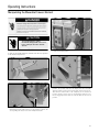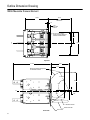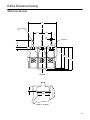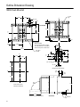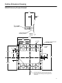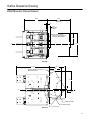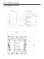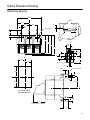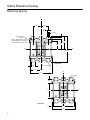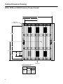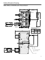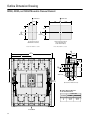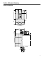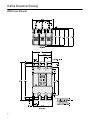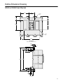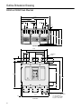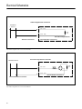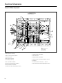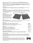
1
SB Encased Systems Breakers
800A—5000A Frame Ratings
Information and Instruction Guide
Circuit breaker indicators shown in this booklet are for illustration purposes only.
Circuit breakers are to be installed in “Discharged” and “Open” positions only.
IMPORTANT
The information contained herein is general in nature and not intended for specific application purposes. It does not relieve the user of responsibility to use
sound practices in application, installation, operation, and maintenance of the
equipment purchased. Siemens reserves the right to make changes in the specifications shown herein or to make improvements at any time without notice or
obligations. Should a conflict arise between the general information contained in
this publication and the contents of drawings or supplementary material or both,
the latter shall take precedence.
NOTE
*Authorized and qualified personnel—
For the purpose of this manual a qualified person is one who is familiar with the
installation, construction or operation of the equipment and the hazards
involved. In addition, he has the following qualifications:
(a) is trained and authorized to de-energize, clear, ground, and tag circuits
and equipment in accordance with established safety practices.
(b) is trained in the correct care and use of protective equipment such as rubber gloves, hard hat, safety glasses or face shields, flash clothing, etc., in
accordance with established safety practices.
(c) is trained in rendering first aid.
SUMMARY
These instructions do not purport to cover all details or variations in equipment,
nor to provide for every possible contingency to be met in connection with
installation, operation, or maintenance. Should further information be desired or
should particular problems arise which are not covered sufficiently for the purchaser’s purposes, the matter should be referred to the local sales office, listed
on back of this instruction guide.
The contents of this instruction manual should not become part of or modify
any prior or existing agreement, commitment or relationship. The sales contract contains the entire obligation of Siemens Energy & Automation, Inc. The
warranty contained in the contract between the parties is the sole warranty of
Siemens Energy & Automation, Inc. Any statements contained herein do not
create new warranties or modify the existing warranty.
SB Encased Systems Breakers
Table of Contents
General Information
2-5
Description
Stationary and Moveable Drawout Elements
Electronic Trip Units for Siemens SB Encased Breakers
6-7
6
7
Frame Installation Instructions
Stationary Drawout Element
Movable Drawout Element
Fixed Mounted
8-10
8
9
10
Installation Instructions
Electronic Trip Unit
Rating Plug
11-14
11
13
Operating Instructions
Operating the SB Encased Systems Breaker
Manipulating the Moveable Drawout Element
15-25
15
18
Internal Accessories
Preliminary Installation Procedures
Preparation for Installation of Electric Motor Operator
External Accessories
Siemens ACCESS Communications
Universal Test Kit (TS-31)
26-30
26
28
31-34
31
34
Outline Dimension Drawings
1200A Stationary Drawout Element
1200A Moveable Drawout
1200A Fixed-Mounted
2000A Stationary Drawout
2000A Moveable Drawout
2000A Fixed-Mounted
3200A, 4000A, and 5000A Stationary Drawout
3200A, 4000A, and 5000A Moveable Drawout
3200A Fixed-Mounted
4000A and 5000A Fixed-Mounted
35-54
35
37
39
41
43
45
47
49
51
53
Electrical Schematics
55-60
Accessory Ratings
61
Solenoid Coil Resistances
62
Primary Current Injection and Field Testing for
SB Breakers
62
NOTE: Information related to specific frame types and catalog numbers does not guarantee product availability. Technical information
may change due to product revisions. Consult Siemens sales office concerning any variation of information contained herein.
1
General Information
Introduction
Siemens SB Encased Systems Breakers bridge the performance gap between Molded Case Circuit Breakers (MCCB)
and Low Voltage Power Circuit Breakers (LVPCB).
Modern computer-aided design and manufacturing tools were
used to effectively blend the technologies of the MCCB and
LVPCB. This combination has resulted in a family of encased
systems circuit breakers that exhibit the most desirable characteristics of each of the parent technologies. Included in
these characteristics are high interrupting capacities, high
withstand capabilities (magnetic stress), high-shorttime
capabilities (overcurrent heating), and high mechanical and
electrical endurances without maintenance.
Applications for SB breakers include main, tie, feeder, and
emergency source breakers in industrial plants, large commercial complexes, and medical and health care facilities. The circuit
breakers are constructed for either fixed or drawout installation.
They can be physically grouped in central distribution switchboards or used separately in stand-alone applications.
The SB breaker is equipped with a two-step stored energy
mechanism for closing and opening the breaker contacts. After
a closing operation, sufficient energy is retained in the two-step
stored energy mechanism to perform the tripping function. The
mechanism may be charged manually with the integrated lowforce charging handle or electrically with the optional electric
motor operator. Pushbuttons, switches, and color-coded indicators allow for easy close and open operations
.
Color keyed label indicates
a choice of three interrupting
ratings.
Extended line/load bus for
2000 through 5000 ampere frames.
Completely insulated/encased
construction.
U-shaped charging handle
allows the user to easily
charge the mechanism
from any angle.
Sealable trip unit cover.
Meets or exceeds applicable
UL and CSA requirements.
Mounting holes are outboard
for ease of access and are
identical for 400 through
2000 ampere frames.
Manual close button
and charging handle
are interlocked.
Compact dimensions allow 6-high
mounting of 800 and 1200 ampere
breakers and 4-high mounting of
2000 ampere breakers in a standard
switchboard section.
Breaker operating
controls grouped
in central escutcheon.
Integral key interlock.
Siemens Encased Systems Breakers
2
One piece molded
base and cover for
structural integrity.
General Information
Frame Sizes and Frame Ampere Ratings
IEC 947-2 Ratings (SBS Units Only)
SB breakers come in four frame sizes with MAX ratings
ranging from 400A to 5000A. All frames are rated for 100%
continuous operation.
Voltage 50/60 Hz
Frame Size and Rating Combinations
415 V AC
lcu
lcs
lcw
100 kA
100 kA
25 kA
100 kA
100 kA
35 kA
100 kA
100 kA
50 kA
100 kA
100 kA
65 kA
690 V AC
lcu
lcs
lcw
65 kA
65 kA
25 kA
65 kA
65 kA
35 kA
65 kA
65 kA
50 kA
65 kA
65 kA
65 kA
Breaker Frame Ampere Size
Breaker MAX Ampere Rating
1200 Amperes
(SBA, SBS only)
400, 800, 1200
2000 Amperes
800 (SBH only), 1200, 1600, 2000
3200 Amperes
2500, 3200
5000 Amperes
2500, 3200, 4000, 5000
1200
2000
SB breakers use interchangeable rating plugs. The rating plug
ampere values (I n ) allows the effective ampere rating of the
breaker to be customized for specific applications. A label on
the front of the breaker identifies the rating plugs that may be
used with that particular breaker.
Available Rating Plugs
Rating Plug Ampere Values (I n )
Overcurrent Protection Configurations
Siemens Electronic Trip Units for SB breakers are available in
seven overcurrent protection configurations to meet specific
protection requirements. Six trip units come equipped with
Adjustable Continuous Current and Long Time Delay functions. Optional protection configurations are:
200, 225, 250, 300, 350, 400
800
400, 450, 500, 600, 700, 800
1200
600, 700, 800, 1000, 1200
1600
800, 1000, 1200, 1600
Protection Configuration
2000
1000, 1200, 1600, 2000
2500
1600, 2000, 2500
Long Time/Short Time
Long Time/Instantaneous
Long Time/Short Time/Instantaneous
Long Time/Short Time/Ground Fault
Long Time/Instantaneous/Ground Fault
Long/Short Time/Instantaneous/Ground Fault
Fixed Long Time/Instantaneous
3200
1600, 2000, 2500, 3000, 3200
4000
2000, 2500, 3000, 3200, 4000
5000
2500, 3000, 3200, 4000, 5000
Interruption and Short Time Ratings
Three short circuit interruption ratings are available for specific
applications. The interruption ratings and short-time ratings are
given in the following table.
UL 489 Interruption and Short Time Ratings
Breaker Frame Size
2000
3200
5000
Type SBA Alternative Interrupt Rating (Blue Label)
240 V AC
480 V AC
600 V AC
65 kA
65 kA
42 kA
85 kA
65 kA
50kA
—
—
Type SBS Standard Interrupt Rating (Black Label)
240 V AC
480 V AC
600 V AC
100 kA
100 kA
50 kA
100 kA
100 kA
65 kA
150 kA
100 kA
85 kA
5000
Blue indicates the alternate or the lowest interrupting category (1200–2000A frames). Black indicates the standard interrupting rating. Red indicates the highest available interrupting
rating for the SB breaker.
400
1200
3200
Type SBS Standard Interrupt Rating (Black Label)
The interruption rating of the SB breaker is specified on the
front cover label and is further identified by a color bar at the
top left of the breaker label.
Rating Plugs
MAX Rating
Frame Sizes
150 kA
100 kA
85 kA
Identifier
LS
LI
LSI
LSG
LIG
LSIG
MLI
The trip unit that may be used with a specific circuit breaker is
identified on the front cover label.
RMS Current Sensing
The trip unit executes the breaker’s overcurrent fault protection functions. Its adjustment flexibility allows you to accommodate load changes and other protection requirements while
still assuring optimum coordination.
A standard trip unit feature is RMS current sensing. RMS
sensing measures the true heating potential of the current
waveform. It allows for more accurate overcurrent protection
and eliminates nuisance tripping due to harmonic distortion of
the current waveform.
Type SBH High Interrupt Rating (Red Label)
240 V AC
480 V AC
600 V AC
—
200 kA
150 kA
100 kA
200 kA
150 kA
100 kA
200 kA
150 kA
100 kA
50 kA
65 kA
Short Time Rating (t=0.5 seconds)
25 kA
35 kA
3
General Information
NOTE: For more information on other standard and
optional trip unit features, see Siemens Electronic Trip
Units for SB Encased Systems Breakers Information and
Instruction Guide Bulletin IPIM-2203 and the Sentron Systems Breaker Energy Communicating Trip Unit
Information and Instruction Guide Bulletin IPIM-2208.
This patented construction provides a higher interrupting
capacity within a smaller housing than can be achieved by
more conventional construction. The electrical insulation property of the thermoset material enhances operational safety.
The insulated case physically isolates and electrically insulates
users from the internal high voltage contacts.
The SB breakers incorporate several installation, operation,
and safety features.
The arc chambers and main contact structure are encased in
the back compartment. The trip unit, controls, springs of the
stored energy mechanism, and optional internal accessories
are located in the front compartment. Access to the front
compartment is by the removable front cover. Since the barrier
between the two compartments is made from the same insulating thermoset material as the housing, the user is physically
isolated and electrically insulated from the main breaker mechanism and contacts when the front cover is removed.
Insulated – Encased Construction
The SB breaker’s housing, internal barrier, and front cover are
molded from a thermoset material with a high-dielectric
strength (electrical insulation). The one piece molded case
(base and housing) provides enhanced structural integrity. A
midbarrier provides outer wall reinforcement, integral arc baffling, and insulation/isolation between the two compartments
of the circuit breaker.
Photo of 2000A Frame Shown for Illustration Purposes Only
4
General Information
Compact Size
For space-limited installations, the 1200A and 2000A frames
offer a common width of 15 1/2 inches, a common depth of
only 12 1/8 inches, a common mounting footprint, and common bus center lines. This compact, shallow depth (even with
drawout breakers) permits stacking of six 800A or 1200A
breakers or four 2000A breakers in a standard switchboard.
This packaging is made possible by the insulated-encased
construction and thermal performance of the SB breaker. Even
when operated at 100% of the frame rating, no additional
ventilation is required for the 1200A and 2000A frames.
2000A Size Frames
1200A Size Frames
0
1
2
3
4
5
6
0
—
✓
✓
✓
✓
✓
✓
1
✓
✓
✓
✓
✓
2
✓
✓
✓
✓
3
✓
✓
4
✓
Possible Number of Frames in a 90-inch Switchboard.
Main Stored Energy Spring in Front Compartment
Example: Three 1200A and two 2000A breaker combination is possible.
Centralized Controls
When operated at 100% of the frame rating, 4000A and
5000A frames require 66 in2 of ventilation space in the top and
bottom of the front cover. The 3200A frames require no additional ventilation. Detailed outline drawings of the breakers
and drawout elements are included in the Outline Dimensions
section starting on page 36.
The manual charging handle, pushbutton control switches, and
color-coded indicators are grouped in the central escutcheon
on the front cover. The U-shaped construction of the charging
handle provides for a firm grip regardless of the position of the
breaker in the switchboard. For safety, the charging handle and
push-to-close pushbutton are interlocked. This interlock
prevents the breaker from being closed unless the charging
handle is in the stowed position, the position to which it will
automatically return when it is released. The interlock also
prevents the breaker from being manually charged if the Close
button is depressed. Operating instructions for the stored
energy mechanism and controls are in the Operating Instructions section starting on page 15.
Bus Spacing and Connections
Specific installation features of SB breakers include common
pole spacings and vertical connections. These pole spacings
allow for a standard bus connection as specified in UL 891.
Detailed outline drawings are contained in the Outline Dimensions section starting on page 36.
Two-Step Stored Energy Mechanism
A two-step stored energy mechanism is used to close and
open the breaker. Energy is initially stored in the main springs
of the stored energy mechanism. When the breaker is closed,
spring energy is consumed and sufficient energy is retained in
the breaker to perform the tripping function.
The stored energy mechanism may be charged manually
(standard) or electrically (optional). Pushbutton controls allow
for easy opening and closing. Color-coded indicators clearly
display the opened or closed status of the circuit breaker and
charged or discharged status of the stored energy mechanism. Once the breaker is closed, the mechanism can be
recharged. The breaker is now prepared for a rapid open-close
or open-close-open operation.
Centralized Controls and Color-Coded Indicators
5
Description
Stationary and Moveable Drawout Elements
Simplified Minimum Depth Drawout Mechanism
The two elements of a drawout constructed SB Encased Systems Breaker are the stationary drawout element and the
moveable drawout element. The stationary drawout element
mounts from the front or bottom into a standard switchboard.
Bottom mounting flanges are provided for optional mounting
arrangements. The moveable drawout element mounts onto
the stationary drawout element’s two extension rails. This
allows the moveable drawout element to be racked in and out
of the stationary drawout element. For inspections, the moveable drawout element must be removed from the extension
rails to a work area. Refer to outline drawings of the two types
of drawout elements starting on page 36.
Each moveable drawout element has four positions: (1) Connected, (2) Test, (3) Unlocked (only), and (4) Unlocked/Withdrawn. A racking mechanism with a low-force pump handle
moves the moveable drawout element between the connected, test, and unlocked positions. The pump handle is an
integral part of the racking mechanism, and no auxiliary racking
device or tool is required. In the unlocked position the moveable drawout element is disengaged from the racking mechanism. The moveable drawout element can be easily pulled
between the unlocked position and the withdrawn position. A
color-coded indicator displays the connect, test, and unlocked
positions of the moveable drawout element.
Bus Stabs
Secondary
Disconnects
(right side)
Line Side
Bus Stab (In
Stationary
Drawout
Element)
Load Side
Connected
Position
Test
Position
Side View Shown
Pushing the release lever with the SB breaker contacts
closed opens the breaker. You do not have to hold the
release lever to rack the moveable drawout element. A directional shift lever determines the direction the moveable
drawout element will move when the pump handle is pulled or
pushed.
Secondary disconnect sliding terminal blocks for terminating
internal accessories are mounted on the sides of the stationary and moveable drawout elements. The secondary disconnects are mated as the moveable drawout element is moved
from the withdrawn position to the unlocked position. The terminal points of the secondary disconnects are identified on
page 59. Step-by-step instructions for operating the racking
mechanism begin on page 18.
Finger
Clusters
Moveable
Drawout
Element
Extension
Rails
Racking
Pump
Handle
Stationary Drawout Element
The integral pump handle and two levers are used to control
the movement of the moveable drawout element. A single
release lever automatically locks the moveable drawout element when it reaches the test or the connected position. The
moveable drawout element is released to move to the next
position by simply pushing and releasing the release lever.
Release
Lever
Position
Indicator
Moveable Drawout Element
6
Directional
Shift Lever
(on side panel)
Description
Electronic Trip Units For Siemens SB Encased Systems Breakers
Trip Units
Advanced True RMS Current Sensing
Two types of trip unit are available for the SB breakers. The TL
(standard) Trip Unit features a full range of industry standard
protective settings. The new, high-performance Systems
Breaker Energy Communicating Trip Unit (SB-EC Trip Unit)
offers advanced metering, protective relaying, time-stamped
logs, and power quality monitoring functions, including an integral keypad and LCD graphical display for menu-driven system
configuration and real-time voltage and current waveform displays. Both units offer unique models to provide an efficient
combination of options versus cost for each application.
The TL Trip Unit and the SB-EC Trip Unit feature advanced
digital-processing techniques to measure the true heating
content of the current waveform. This True RMS value of
current measurement virtually eliminates nuisance tripping
due to the presence of harmonics on the distribution bus.
TL Trip Unit
The TL Trip Unit offers adjustable LI, LIG, LSI, and LSIG trip
settings and accessory ammeter and load alarm or ground
current meter with alarm output.
SB-EC Trip Unit
Rating Plug
In=1000A
The Energy Communicating trip unit for the SB offers local and
remote programming of all overcurrent trip functions as well
as power and energy measurement, advanced protective
relays and alarms and power quality functions (harmonics and
waveform capture and display).
NOTE: For details on these trip units, refer to the Siemens
TL Trip Unit Bulletin IPIM-2203 and the Siemens SB-EC Trip
Unit Bulletins IPIM-2208.
Rating
Plug
Curve
Adjustments
Status
Indicators
MAX
Rating
Watchdog
LEDs
MAX Rating
= 20
00A
Graphical
Backlit
LCD
1000A
Fault Indicators
Integral
Keypad
Built-in
Test Functions
Plug-in
Display Module
NOTE:Earlier model trip units may use (I r ) as the
Rating Plug Designator and (In ) to denote (MAX
Rating). The designations for the current model
trip unit are shown at left. Note, however, that the
change in designation has no effect on the switch
settings used for selecting Continuous, Long Time,
Short Time, Instantaneous, and Ground Fault
pickup and delay values.
RS-232
Communication Port
TS-31 Test
Connector
Typical Trip Adjustment Unit Panel
Interchangeable Rating Plugs
SB trip units use field interchangeable rating plugs. This allows
the ampere rating of the circuit breaker to be field-modified
and provides security against indiscriminate changes in the
breaker’s ampere rating.
SB-EC Trip Unit
7
Frame Installation Instructions
Stationary, Moveable, and Fixed-Mounted Drawout Elements
Installation instructions for systems breakers, trip units, and
rating plugs are presented in this section. Installation instructions for accessories that may be installed in the field are
presented in the Accessories section.
Installing Drawout Constructed SB Breakers
Drawout constructed SB breakers are designed to be installed
from the front into a switchboard with a minimum width opening: 19 in. (1200A and 2000A frames), 20.36 in. (3200A frame),
and 28.34 in. (5000A frame). The stationary drawout element
may be secured in the switchboard at the front and rear to vertical supports or at the top and bottom to horizontal supports.
Installing the Stationary Drawout Element
Prepare the switchboard for installation of the stationary
drawout element in accordance with the outline drawings
located in the Outline Dimension Drawings section starting on
page 36. The locations of the mounting holes are depicted on
the drawings.
Carefully uncrate the stationary drawout element. Remove all
packing material with the exception of the tie wraps holding
the extension rails in place. Depending upon the installation
scheme, it may be necessary to remove the tie wraps on the
extension rails just prior to securing the stationary drawout
element in the switchboard. If the stationary drawout element
is secured to a pallet, remove the securing device.
The bottom of the stationary drawout must be secured to the
switchboard using four 3/8-inch bolts. Additional mounting
hardware may be used to attach the top and front of the
stationary drawout but is not required.
The stationary drawout element can be manually lifted and
held in position as it is being installed. However, if preferred,
the two holes identified as lifting points on the outline drawing
may be used to attach a lifting device.
8
Attach lifting device to identified lifting points only.
NOTE: The two rear holes are located so that the stationary drawout element can be easily balanced as it is being
lifted by a crane or hoist. Do not lift the stationary
drawout element using only the two top front holes. If
preferred, the device can be lifted using all four top holes.
Lifting devices should not be attached to any other points. The
stationary drawout element should not be lifted by the primary
stabs.
Lift the stationary drawout element into position and secure it
in place. Remove the lifting device.
Remove the tie wraps securing the extension rails. Check to
ensure that no packing or other foreign material impedes rail
movement.
Frame Installation Instructions
Stationary, Moveable, and Fixed-Mounted Drawout Elements
Installing the Moveable Drawout Element
The outline drawings of the moveable drawout elements are
located in the Outline Dimension Drawings section starting on
page 36.
Carefully uncrate the moveable drawout element and remove
all packing material with the exception of the wire ties holding
the racking pump handle in place. Items such as a label for a
dead front shield and keys for the SB breaker with a key interlock accessory may be taped to the top of the moveable
drawout element. If the moveable drawout element is secured
to a pallet, remove the securing device.
Lift by using the rear guide posts (one is located on left side
and one on right).
Lift the moveable drawout element over the extension rails.
For the 1200A and 2000A frame, align the moveable drawout
element so that the support brackets straddle the inside guide
rails, and carefully lower the moveable drawout element onto
the rail guides. For the 3200A and 5000A frame, align the
moveable drawout element so that the rollers straddle the
extension rails, and carefully lower the moveable drawout
element onto the extension rails. Remove the lifting device.
Remove the tie holding the racking pump handle.
Preferred lifting arrangement.
Attach the lifting device accessory as illustrated. If lifting straps
are used instead of the lifting device accessory, the lifting
straps should go between the primary contacts. In either
arrangement, the moveable drawout element may be balanced as it is being lifted by a crane or hoist. The moveable
drawout element should not be lifted by the primary contacts.
Pull out the extension rails on the stationary drawout element
until they hit a solid stop.
Rollers and Rail
9
Frame Installation Instructions
Stationary, Moveable, and Fixed-Mounted Drawout Elements
To correctly engage the moveable drawout element with the
racking mechanism, the crank pins on the sides of the moveable drawout element must be in the Unlocked position as
illustrated and the release lever must be in the Up position.
During shipping and handling, the crank pins may have rotated
out of position. If so, rotate them to the correct position. The
moveable drawout element may now be moved/racked into
the stationary drawout element. Racking instructions start on
page 18.
Release Lever Mechanism
Installing Fixed-Mounted SB Breakers
Crank Pin in Unlocked Position
Prepare the switchboard for installation of the SB breaker in
accordance with the outline drawings at the end of this section. The outline drawings are located in the Outline Dimension
Drawings section starting on page 36. The locations of the
mounting holes and the recommended screws are depicted
on the drawing. All four, six or eight mounting screws will be
used to secure the breaker to the switchboard.
Carefully uncrate the breaker and remove all packing material. If
the breaker is secured to a pallet, remove the securing device.
Crank Pin in Test Position
Lifting straps should go between the stabs.
Attach the lifting straps as illustrated. The breaker should not
be lifted by the primary stabs; the lifting straps should go
between the stabs. In this arrangement the breaker may be
easily balanced while it is being lifted by a crane or hoist.
Crank Pin in Closed or Connected Position
10
Lift the breaker into position and secure it with 4 mounting
screws for 1200A and 2000A frame sizes, 6 mounting screws
for 3200A frame size, and 8 mounting screws for the 5000A
frame size torqued to 13–15 ft-lbs. Remove the lifting straps.
Installation Instructions
Electronic Trip Unit
Note: If you are installing a SB-EC Trip Unit, refer to the
Information and Instruction Guide for this device (IPIM2208).
To install the trip unit, remove the breaker’s front cover. This is
done by removing the four recessed Phillips head screws in
positions 2, 3, 6, and 7, as well as the four Phillips head screws
in positions 1, 4, 5, and 8, which hold the front cover in place.
NOTE: For more complete information on other standard
and optional features of the electronic trip units, see
Siemens Electronic Trip Units for SB Encased Systems
Breakers Information and Instruction Guide Bulletin IPIM2203 and the Sentron Systems Breaker Energy Communicating Trip Unit Information and Instruction Guide
Bulletin IPIM-2208.
! CAUTION
Do not attempt to install a trip unit
with the breaker Closed or Charged.
Make certain breaker is Open and
Discharged as shown above. Personal
injury or mechanical damage may occur.
Installation of Electronic Trip Unit
The SB breaker has a built-in interlock device that prevents the
breaker from being closed when there is not an installed trip
unit. This same interlock device will trip the breaker when the
trip unit is removed.
1
2
2. Lift off front cover.
On trip units with ground fault protection, the ground fault
selection switch on the side of the trip unit must be set to the
appropriate sensing scheme—Residual or Source Ground/Zero
Sequence—before installing the trip unit. The trip unit is preset
at the factory to a residual sensing scheme.
3
4
5
6
7
8
3. Set ground fault selection switch.
1. Remove 8 screws from breaker front cover.
11
Installation Instructions
Electronic Trip Unit
Before attempting to install the trip unit, check the label on the
side of the unit to make sure that it is the correct unit for the
SB breaker. A built-in rejection scheme will prevent the installation of a trip unit into a breaker for which it is not intended.
4. Check label on side of trip unit.
This scheme consists of two pins on the support plate on
which the trip unit will set and two matching holes in the bottom of the trip unit. If the holes in the bottom of the trip unit
do not aligned with the pins, the trip unit cannot be installed in
the SB breaker. If there is any doubt about a trip unit being the
correct unit for a breaker, hold the trip unit upside down and
check the alignment of the pins and holes.
6. Lower trip unit onto support plate.
After the connector has been mated, lower (push) the trip unit
onto the support plate. The pins on the support plate will fit
into the holes in the bottom of the trip unit.
7. Secure trip unit.
5. Mate pin connectors.
Mate the connector half on the back of the trip unit with its
corresponding connector half in the breaker.
Secure the trip unit in place with the retaining screw located at
the top of the trip unit. Torque 6 to 8 in-lbs. If the trip unit top is
not secured correctly, the interlock will prevent the breaker
from closing.
NOTE: Before energizing breaker, be sure to install a
correct rating plug. See page 13.
12
Installation Instructions
Electronic Trip Unit
Rating Plug
8. Replace circuit breaker front cover.
Replace the front cover. Then, replace the eight front cover
screws.
! CAUTION
Do not attempt to install a rating plug
with the breaker Closed or Charged.
Make certain breaker is Open and
Discharged as shown above. Personal
injury or mechanical damage may occur.
Verify that breaker is Open before inserting or removing a
rating plug. Breaker should always be in the Open position
when there is no rating plug in the trip unit.
1. Remove trip unit screws that hold the transparent cover.
The rating plug and adjustments on the front panel of the trip
unit are protected by a transparent cover. Before installing a
rating plug or setting the adjustments on the trip unit, this
cover must be removed. Unscrew the two screws that hold it
in place.
9. Re-install the eight screws that hold the front cover in place.
2. With a small screwdriver, gently pry the cover loose at one end and
remove it carefully.
13
Installation Instructions
Rating Plug
! CAUTION
Do not attempt to force an incorrect
rating plug into a trip unit. Mechanical
damage may occur. The receptacle in the
trip unit has been keyed to prevent the
insertion of an incorrect rating plug.
5. To replace the cover, bow it slightly in the middle and snap into
place.
3. Check label on the rating plug.
Check the rating plug label to verify that it is the correct plug
for the trip unit. If it is not a correct plug, the pins will not mate
with the plug receptacle.
After the rating plug has been inserted and the necessary setting adjustments have been made, replace the cover by sliding
the protective shield into the top lip of the trip unit, bow it
slightly in middle, and press it down with your thumb on
bottom to snap shield into place. Replace the two special
retaining screws.
NOTE: For more complete information on the electronic
trip units, see Siemens Electronic Trip Units for SB
Encased Systems Breakers Information and Instruction
Guide Bulletin IPIM-2203 and the Sentron Systems
Breaker Energy Communicating Trip Unit Information and
Instruction Guide Bulletin IPIM-2208.
4. To insert rating plug, align plug with plug receptacle and press into
place.
To insert a rating plug in the trip unit, align the plug with the
plug receptacle and press the plug into place. The clips on the
plug secure the plug, eliminating the need for screws or
latches.
To remove a rating plug, squeeze the clips and pull the plug
from the plug receptacle. Because the plug is held in place by
compression, some force is required to remove the plug. Do
not close the breaker with the rating plug removed from the
trip unit.
14
6. The cover may be sealed with a lead seal for tamper evident
protection.
After the cover has been replaced, a wire may be inserted
through the holes in the screws and secured with a meter
seal. This will help prevent tampering.
Operating Instructions
Operating the SB Encased Systems Breaker
General Instructions
Operating the SB Breaker
Instructions for charging the stored energy mechanism, closing and opening the breaker, and positioning and rotating the
moveable drawout elements of the drawout-constructed SB
breakers are presented in this section. The trip unit’s standard
test and monitoring functions are also presented. These
instructions are grouped into two parts: Operating the SB
Breaker and Manipulating the Moveable Drawout Element.
Before bringing the SB breaker on-line, the user should be
familiar with the test and monitoring functions. Operating
instructions for the accessories are presented in the Accessories Section.
The SB breaker controls and charging handle for the stored
energy mechanism are located in the central escutcheon of
the front panel. Standard controls are Push-to-Close and Pushto-Open pushbuttons. Color-coded indicators display the
charged/discharged status of the stored energy mechanism
and the closed/open status of the breaker. Positions are available in the central escutcheon for a Key Interlock and an
Electric Close pushbutton.
A. Stored energy
mechanism spring
charged/ spring
discharged status
indicator
B. Push-to-Close
pushbutton
A
D
B
E
C
F
C. Position for
Electric Close
pushbutton
D. Circuit breaker
Closed/Open
status indicator
E. Position for
Key Interlock
F.
Push-to-Open
pushbutton
SB Encased Systems Breaker Controls and Indicators
15
Operating Instructions
Operating the SB Encased Systems Breaker
Discharged indicator points to Spring Charged. The charging
handle returns to the stowed position when released. While
manually charging the breaker with the charging handle, do
not depress the Push-to-Close or Push-to-Open push buttons.
If an optional electric motor operator is employed, the electric
operator automatically recharges the stored energy mechanism when the breaker is closed. If the electric operator is disabled, the stored energy mechanism may be charged
manually.
Manually Charging the Stored Energy Mechanism
The stored energy mechanism may be charged with the SB
breaker open or closed. If the stored energy mechanism is
charged with the breaker open, sufficient energy is stored to
close and then open the breaker without recharging. If the
stored energy mechanism is charged with the breaker closed,
the operating sequence of open-close-open may be executed
without recharging. To manually charge the stored energy
mechanism, pull the charging handle.
! CAUTION
Do not exert further downward pressure
when springs are charged or handle is
against bottom stop as shown in the
illustration below. Potential damage to
housing may occur.
Five or six full strokes, or several partial strokes are required to
fully charge the stored energy mechanism. When the stored
energy mechanism is fully charged, Spring Charged/Spring
To manually charge the stored energy mechanism, pull the charging handle downward five or six strokes until indicator points to
“Spring Charged.”
16
Operating Instructions
Operating the SB Encased Systems Breaker
Discharging the Stored Energy Mechanism Without
Closing the SB Breaker
Discharging the energy in the stored energy mechanism without
closing the breaker creates an abnormally high shock condition
on the breaker. Avoid this procedure except for safety and/or
emergency reasons. To discharge the energy, push and hold the
Open pushbutton and then push the Close pushbutton.
On electrically-operated breakers, the electric operator should
be disabled (one way is to remove the fuse) before discharging
the stored energy. Otherwise, the electric operator automatically recharges the springs. To close the breaker, standard closing-prevention devices require that the following: (1) a trip unit
must be installed in the SB breaker, (2) the stored energy
mechanism must be fully charged, and (3) the charging handle
must be in the stowed position. On drawout constructions,
the release lever must be in the release-engaged position (up
position).
Accessories that inhibit the breaker from being locally closed
are presented in the Accessories section. Included are a closing-blocking device for use with remotely-operated circuit
breakers, key interlocks, and other locking devices.
Closing the SB Breaker Locally
Before the breaker can be closed, the stored energy mechanism must be fully charged and all of the closing-prevention
devices (and accessories) must be in the noninhibiting state or
position. In this condition, all that is required to close the
breaker is to push the Close pushbutton. When the breaker is
closed the Contacts Closed/Contacts Open indicator will point
to Contacts Closed.
Indicates that the circuit breaker is Closed with the springs in
the Charged position.
Indicates that the circuit breaker is Open with the springs in
the “Discharged” position.
Opening the SB Breaker Locally
To locally open the breaker, push the Open pushbutton. When
the breaker is open, the Contacts Closed/Contacts Open indicator will point to Contacts Open.
Built-in safety devices trip the SB breaker if the trip unit is
removed or the release lever on the drawout mechanism is
depressed. Performing the trip unit integral test in the trip
mode also trips the breaker.
Discharging energy from the stored energy mechanism without closing contacts.
17
Operating Instructions
Manipulating the Moveable Drawout Element
Manipulating the Moveable Drawout Element
There are four positions of the moveable drawout element.
These four positions are defined as Connected, Test,
Unlocked, and Unlocked/Withdrawn. The connected position
is the normal operating position of the breaker. In this position
the primary stabs and secondary contacts are connected and
the moveable drawout element is locked into position. In the
test position, the primary stabs are disconnected, the secondary contacts are connected, and the moveable drawout element is locked into position. The unlocked position is a
transition position between the test position and the withdrawn position.
Physically, the unlocked position and test position are the
same. However, in the unlocked position, the moveable
drawout element is disengaged from the drive mechanism.
The breaker should not be tested when the moveable drawout
element is in the unlocked position. In the unlocked/withdrawn position, the secondary contacts are disconnected and
the moveable drawout element is disengaged from the
release mechanism. The moveable drawout element can be
pulled to the fully withdrawn position where it can be
inspected or removed from the stationary drawout element.
NOTE: Relationship of finger clusters and bus will be the
same for all drawout frames. Configurations may change.
Bus
Stab
Bus
Stab
Finger
Cluster
Finger
Cluster
Test
Connected
Connected Position
Moveable drawout element in the Connected position.
Bus
Stab
Bus
Stab
Finger
Cluster
Finger
Cluster
Test
Unlocked
Test or Unlocked Position
Moveable drawout element in the Test or Unlocked position.
Bus
Stab
Finger
Cluster
Unlocked
Withdrawn Position
Moveable drawout element in the Withdrawn position.
18
Bus
Stab
Finger
Cluster
Withdrawn
Operating Instructions
Manipulating the Moveable Drawout Element
Directional Shift Lever
Racking Controls
A built-in, low-force pump handle and two control levers are
used to rack the moveable drawout element between the
Connected, Test, and Unlocked positions.
The directional shift lever determines the direction the movable
drawout element will move when it is racked. The lever has three
positions: racking-out, neutral, and racking-in. When the lever is in
the racking-out position (pulled all the way out), the moveable
drawout element may be racked from the Connected position to
the Test position, and from the Test position to the Unlocked position. When the lever is set in the neutral position (located midway between the racking-in and racking-out positions), the
racking pump handle is disengaged from the racking mechanism.
In the racking-in position (pushed all the way forward), the
moveable drawout element may be racked from the Unlocked
position to the Test position, and from the Test position to the
Connected position.
E
D
A
B
1. Racking-out Position
C
F
A. Moveable
Drawout
Element
C. Position
Indicator
E. Racking
Pump
Handle
B. Release
Lever
D. Stationary
Element
F.
Directional
Shift Lever
2. Neutral Position
Racking Controls Locations
3. Racking-in Position
19
Operating Instructions
Manipulating the Moveable Drawout Element
Racking Pump Handle
Drawout Position Indicator
A low-force pump handle is used to rack the moveable
drawout element. The pump handle is an integral part of the
racking mechanism, eliminating the need for an auxiliary racking device. If there is any resistance in returning the pump
handle to the stowed position, set the directional shift lever to
the neutral position. The racking pump handle can then be
returned to the stowed position.
A color-coded indicator displays the position of the moveable
drawout element: connected (red), test (yellow), and unlocked
(yellow). When the moveable drawout element is being racked
from one position to another position, the indicator will display
the more critical position.
The Connected position is defined to be more critical than the
Test position and the Test position to be more critical than the
Unlocked position. This means that when racking the moveable drawout element from the Connected position to the Test
position, the indicator will continue to display the Connected
position until the moveable drawout element has been racked
all the way to the Test position. Conversely, when racking from
the Test to the Connected position, the indicator will display
the Connected position as soon as the SB breaker is moved
toward the Connected position. The process is the same when
racking between the Test and Unlocked position.
Racking Pump Handle in Stowed Position
Unlocked
Position
(Yellow)
Test
Position
(Yellow)
Drawout Position Indicator
Racking Pump Handle in Full Stroke Position
20
Connected
Position
(Red)
Operating Instructions
Manipulating the Moveable Drawout Element
Fully Withdrawn and Unlocked Positions
To move the moveable drawout element from the Fully
Withdrawn position to the Unlocked position, push toward the
bus connections until the moveable drawout element hits a
solid stop. The secondary disconnects on both sides of the
moveable and stationary drawout elements will mate as the
moveable drawout element moves into the Unlocked position.
When the moveable drawout element is in the Unlocked
position, the pointer on the position indicator will point to the
Unlocked symbol. To move the moveable drawout element
from the Unlocked position to the Fully Withdrawn position,
fully extend the side rails until they rest in a horizontal position.
Then pull the moveable drawout element to the ends of the
rails.
Pushing and pulling the moveable drawout element between the Withdrawn and Unlocked postiions.
21
Operating Instructions
Manipulating the Moveable Drawout Element
! CAUTION
To avoid damaging the racking mechanism, always pull the release lever
before racking the moveable drawout
element.
Unlocked Position to Test Position
Racking the moveable drawout element from the Unlocked
position to the Test position engages the moveable drawout
element with the stationary drawout element. The physical
position of the moveable drawout element will be unchanged.
Complete the steps that follow to rack the moveable drawout
element from the Unlocked position to the Test position.
3. Pump the racking pump handle until the moveable drawout element
has reached the Test position.
NOTE: If extension rails are pulled out, push them in until
they hit a solid stop.
1. Push in the directional shift lever. This is the racking-in position.
4. When the moveable drawout element reaches the Test position, the
release lever will automatically return to the release-engaged (up)
position, the racking pump cannot be pumped, and the position
indicator will display that the moveable drawout element is in the
Test position.
2. Pull the release lever down to the release-disengaged position.
(Illustrated beneath padlock device.) If the breaker contacts are
closed, pulling the release lever down will trip the breaker.
22
Operating Instructions
Manipulating the Moveable Drawout Element
! CAUTION
To avoid damaging the racking
mechanism, always pull the release lever
before racking the moveable drawout
element.
Test Position to Connected Position
To rack the moveable drawout element from the Test position
to the Connected position.
3. Pump the racking pump handle until the moveable drawout element
is in the Connected position.
1. Push in the directional shift lever. This is the racking-in position.
4. As soon as the moveable drawout element is racked from the Test
position, the position indicator will display that the moveable
drawout element is in the Connected position. However, the moveable drawout element will not be completely in the Connected
position until the release lever has automatically returned to the
release-engaged position. Push the side rails back into the stored
position.
2. Pull the release lever down to the release-disengaged position.
(Illustrated beneath padlock device.) If the breaker contacts are
closed, pulling the release lever down will trip the breaker.
23
Operating Instructions
Manipulating the Moveable Drawout Element
! CAUTION
To avoid damaging the racking mechanism, always pull the release lever
before racking the moveable drawout
element.
Connected Position to Test Position
To rack the moveable drawout element from the Connected position to the Test position, ensure that the SB breaker is open. (If
the breaker is closed and the release lever is moved downward
to the interlock disengaged position, the breaker will trip.)
3. Pump the racking pump handle until the moveable drawout element
is in the Test position.
1. Pull out the directional shift lever. This is the racking-out position.
4. When the moveable drawout element reaches the Test position, the
release lever will automatically return to the interlock engaged position, the racking pump handle cannot be pumped, and the position
indicator will display that the moveable drawout element is in the
Test position.
2. Pull the release lever down to the interlock disengaged position.
(Illustrated beneath the padlock device.) If the breaker contacts are
closed, this action will trip the breaker.
24
Operating Instructions
Manipulating the Moveable Drawout Element
! CAUTION
To avoid damaging the racking mechnism, always pull the release level
before racking the moveable drawout
element.
Test Position to Unlocked Position
4. Pump the racking pump handle until the moveable drawout element
is in the Unlocked position.
Racking the moveable drawout element from the Test position to
the Unlocked position disengages the moveable drawout
element from the stationary drawout element. The physical
position of the moveable drawout element will be unchanged. To
rack the moveable drawout element from the Test position to
Unlocked position, complete the following steps:
5. When the moveable drawout element reaches the Unlocked position, the release lever will automatically return to the interlock engaged (up) position and the position indicator will display the
Unlocked position. Pull out the extension rails until they hit a solid
stop before pulling out the moveable drawout. (3200-5000A only).
1. Pull out the directional shift lever. This is the racking-out position.
2. Pull the release lever down to the interlock disengaged position.
(Illustrated beneath the padlock device.) If the breaker contacts are
closed, this action will trip the breaker.
3. If breaker will be withdrawn: Extend side rails fully until they are in
a horizontal position (3200-5000 amp only).
Bus
Stab
Bus
Stab
Finger
Cluster
Finger
Cluster
Test
Unlocked
Relative Position of Finger Clusters to Bus Stabs
25
Internal Accessories
Preliminary Installation Procedures
NOTE: Refer to the separate SB Accessories Installation
and Instruction Guide for information on Accessory
Installation and ratings. Refer to the separate SB Trouble
Shooting Guide for trouble-shooting tips.
! CAUTION
Mechanism can cause severe
injury when cover is removed.
Before removing cover, push open
button, push close button, and then
push open button again.
! CAUTION
Install all accessories with the breaker
Open and Discharged as shown above.
To avoid injury or damage to equipment,
do not install accessories with breaker
in a Closed or Charged position.
NOTE: Siemens recommends that all accessories be
installed using the instruction information accompanying
the accessory, or by referring to the Accessory Manuals
(IPIS-00105 and IPIS-00106).
26
1. Before removing the cover check to be sure the circuit breaker main
contacts are open and the closing springs are discharged by first
pushing the open button.
2. Push the close button and then repeat pushing of the open button.
Verify that the status indicators show Spring Discharged and
Contacts Open.
Internal Accessories
Preliminary Installation Procedures
3. Remove the breaker cover by first removing the four #10 Phillips
head screws at the corners and the four 1/4” Phillips head screws
in recesses in cover.
5. Remove the trip unit if installed, by removing trip unit retaining
screw.
4. Remove cover.
6. Slide the trip unit up to clear the support bracket pins.
7. Remove the trip unit by pulling the trip unit away from the trip unit
plug.
27
Internal Accessories
Preparation For Installation of Internal Accessories
Accessories
The full family of accessories available for Siemens SB breakers
are presented in this section. The accessories are divided into
two groups. Group one consists of accessories installed in the
front compartment of the circuit breaker (Internal Accessories).
.
! CAUTION
Install all accessories with the breaker
Open and Discharged as shown above.
To avoid injury or damage to equipment,
do not install accessories with breaker
in a Closed or Charged position.
NOTE: Refer to the separate SB Accessories Installation
and Instruction Guide for information on Accessory
Installation and ratings. Refer to the separate SB Trouble
Shooting Guide for trouble-shooting tips (IPIS-001020599).
Group two consists of accessories installed or used outside of
the front compartment (External Accessories). The External
Accessories are installed on the exterior of the circuit breaker,
on the drawout elements, or at remote locations. When the
installation location is referred to as the right side or left side, it
is with reference to the user’s right or left side when facing the
front of the breaker.
Components required to access or activate an accessory such
as a switch or indicator at a remote location are assumed to be
user supplied unless otherwise stated.
Group One – Internal Accessories
Secondary connections to remote locations are made to secondary disconnects on drawout breakers and to control terminal blocks on fixed-mounted breakers. The terminal points for
all internal accessories are illustrated in the control terminals
diagram on page 59.
Control power connections for accessories are made through
terminal blocks mounted on the sides of the breaker. Drawout
constructed breaker control power connections are made
through secondary disconnects mounted on the stationary and
moving elements.
Electric Operator Troubleshooting Guide
Symptom
Solutions
Motor does not run.
1. Check for springs already charged by checking spring charge indicator.
2. Check for rated voltage at LT1 (+) and LT5 (–).
3. Check motor fuse – requires 2.5A Slo-Blo fuse.
4. Check all wiring connections.
5. If the lamp connected to LT4 is blinking slowly (1 second on, 2 seconds off), manually charge breaker.
Motor runs for 20 seconds, does not charge
springs, optional lamp on LT4 blinks slowly
(1 second on, 2 seconds off).
1. Breaker has been partially charged manually. Complete manual charge operation with the charging handle. Electric
motor operator should now be engaged for the next charge cycle.
Breaker will not close electrically.
1. Check to see if springs are charged by checking charged indicator flag.
2. Check for power on LT1 (+) and LT5 (–).
3. Check for power on LT2 (+). If power is on LT2 (+), remove and re-apply.
4. Check to see if breaker is locked in open position by either padlocking device, kirk key, or drawout interlock.
5. Check to see if breaker handle is fully seated in cover.
6. Check all wiring connections.
7. Check motor fuse – requires 2.5A Slo-Blo fuse.
8. Verify latch check switch adjustment
Lamp on LT4 blinks slowly (1 second on,
2 seconds off).
1. Manually charge breaker springs. Lamp on LT4 should remain on.
28
Internal Accessories
Preparation For Installation of Internal Accessories
Removing the Left and Right Drawout Mechanism
Complete the following steps to remove the crankshaft.
5. Take off the left and/or right mechanism assemblies (as required) by
removing the two, three or four 5/16-inch bolts and nuts on each
side.
1. Remove the E-rings from the bar cap pin on each side.
Note: e-ring may be located on outside of plate.
*Note this location for reassembly.
2. Remove the bar cap pin from each side.
Note: It may be necessary to remove the bar cap pin from the
opposite side. Note this orientation for reassembly.
3. Rotate the bar caps upward.
Reinstalling the Left and Right Drawout Mechanism
Remove cover. Install cover, making sure metal clips are in place on
left and right.
1. Attach the left and/or right mechanism assemblies to the breaker
using two, three or four 5/16-inch bolts and nuts. Torque the bolts to
16 to 20 ft.-lbs.
Using 1/4” nut driver, reinstall the 2 screws into center recesses of
either side mechanism assembly.
4a. Lift out the crankshaft assembly. (Rotating the crankshaft back and
forth makes it easier to remove.)
4b. Using 1/4” nut driver, remove 2 screws from center recesses of left
or right mechanical assembly.
2. Rotate the bar caps upward.
29
Internal Accessories
Preparation For Installation of Internal Accessories
5. Install the bar cap pins through the bar caps and left and right mechanism assemblies with the head of the pins toward the center of the
breaker.
Note: Bar cap pin should be reinstalled on the side it was originally
removed.
3. Install the crankshaft assembly by positioning the crank pin anywhere between the unlocked and connected positions as shown
and lowering the crankshaft to the bottom of the slot. During crankshaft assembly installation, the lock bar must be held in the proper
position. This may be done by inserting a screwdriver into the
double-D hole (if present) and pushing until a solid stop is felt. If the
double-D hole is not present, use the rectangular cutout to gain
access to the lockbar as shown.
.
6. Install an E-ring on each bar cap pin.
Note: e-ring should be installed on the side of the plate that it
was orginally removed.
7. Complete steps 1 to 4 on Unlocked Position to Test Position on page
22 to verify the lock bar is in the proper position. You should have to
pull the interlock lever down before racking the drawout, and the lever should return to the engaged position when the drawout reaches the unlocked, test, or connected positions. If the interlock lever
does not operate in this manner, the lock bar is not in the proper position and step 3 above must be repeated.
Perform steps 1-5 on test position to unlocked position on page 25,
returning crankshaft to correct position before breaker installation.
NOTE: Failure to ensure proper drawout operation can
cause the drawout to not lock in the correct position.
Injury to personnel and damage to equipment can result.
4. Rotate the bar caps downward.
30
External Accessories
Siemens ACCESS Communications System
data displays and trip unit configuration via Siemens SBWIN
software. Remote open/close operation is also possible if a
remote open/close relay is installed.
Expansion Plug
Breaker Type
Frame Size
Mounting Type
SB ICCB
1200A, 2000A
Fixed
EPSBFMK Drawout
EPSBDMK SB ICCB
SB Breaker Communication
All SB Circuit Breaker trip units feature two levels of communication: Zone Selective Interlocking and ACCESS System openprotocol communications. The SB-EC Trip Unit is fully equipped
for direct integration into ACCESS or compatible communication systems. It does not require a MTA (Muliplexer/Translator
for ACCESS communications and Zone Interlocking) or expansion plug (EP).
If zone selective interlocking alone is specified for a SB-EC or
TL Trip Unit, a MTZ (Muliplexer/Translator for Zone Interlocking) and an EP are required.
If zone selective interlocking and full ACCESS communications
are specified for a TL Trip Unit, a MTA and an EP are required.
Sensitrip
MCCB
3200A, 5000A
ALL
Cat. No.
Fixed
EPSB4FMK Drawout
EPSB4DMK ALL
EP
Factory wired when ACESS communications or ZSI is ordered for
the SB breaker from the factory.
The EP is an electronic interface and isolation module required
to integrate a breaker into an ACCESS system. When required,
one expansion plug is used for each circuit breaker in the
system and is used to interface trip units to a MTZ or MTA.
The expansion plug is always necessary for zone interlocking
or full ACCESS communications for the TL Trip Unit. It is not
required for ACCESS communications with the SB-EC Trip
Unit. However, an expansion plug is required for zone interlocking with the SB-EC Trip Unit.
The MT (as in MTA and MTZ) is a minicomputer that collect
data from and transmit data to difference components
integrated into the ACCESS communications system. The MT
can support up to eight field devices. Multiple MTs can be
connected, although an expansion plug may be required for
each trip unit.
Siemens WinPM supervisory software (version 4.0 or later)
delivers a powerful energy management system providing
sophisticated monitoring capability to a host computer and
other components in the electrical distribution system at
affordable cost. It also provides process control, including peak
demand, trend analysis, waveform analysis, and harmonic
calculations and displays. These functions help pinpoint energy
consumption, power quality issues, and the energy cost of any
process. Outages and potential outages can be quickly
diagnosed and plans can be generated for expansion and
preventative plant maintenance.
NOTE: Refer to Bulletin IPIM-2211 for additional information on the MTA and Siemens WinPM software.
Communications is accomplished via EIA-485 twisted pair
wire or modem. It provides communications to a remote site
and allows access to multiple plants. WinPM uses a Microsoft
Windows dynamic data exchange (DDE) server that allows
data exchange to other Windows-based software such as
spreadsheets and word processors.
Protocol Converters are available from the Siemens ACCESS
group for connecting a variety of open and proprietary automation protocols, including Profibus DP, LonWorks, Siemens S7
PLC, and many other third-party PLCs and associated networks. The SB-EC Trip Unit’s EIA-2342 communications port
provides additional PC communications for available trip unit
EPSB
Expansion Plug Dimension Drawing
SB Systems Breakers
The following sections describe both types of SB trip units,
the standard Type ‘TL’ unit with rotary switches, and the SB
Energy-Comm (SB-EC) Trip Unit with keypad and display. Since
the SB-EC Trip Unit has integral communications capability, the
MTA device is not required to connect within an ACCESS system, however for SB-EC Trip Units in a ZSI system, an MTZ or
MTA is required.
The type EPSB expansion plug is factory wired to the SB
breaker trip unit’s rear connector and also located near and
wired to the SB breaker’s secondary terminal block for fixed
mount breakers or sliding disconnects for drawout breakers.
These connections are factory wired when the SB breaker is
ordered with the standard switch based type ‘TL’ trip unit for
ACCESS communications or for any trip unit with ZSI capability.
Installed ICCB SB breakers without communication capability
may be field upgraded for communication capability by
Siemens Field Service personnel only.
31
External Accessories
Siemens ACCESS Communications System
2. If multiple MT’s are used, the “Com” terminal from the first
MT’s “SEABus Out” port must be connected to the “Com”
terminal of the next MT’s “SEABus In” port on each MT being
used.
The MTCSB cable is used to connect an MTA or MTZ to an
EPSB expansion plug via the SB breaker secondary terminal
block or sliding disconnect.
A. SB Breaker Zone Selective Interlocking (only)
3. Based on the site’s coordination study, configure the expansion plug’s DIP switches for Short Time and/or Ground Fault
ZSI per the EP Information and Instruction Sheet.
1. All SB Breaker Trip Units
Components Required:
4. Configure the MTZ to identify the zones for each breaker, per
the site’s coordination study and information and instruction
sheet. Refer to figure 1 for system connections diagram.
• Siemens type MTZ – one per 8 trip units
• Siemens type EPSB expansion plug – one per trip unit,
factory wired
• Siemens type MTCSB cable – one per trip unit
Installation:
1. When the factory-installed ZSI option is present, the EPSB expansion plug is already wired to the breaker and secondary
control terminals. Connect an MTCSB cable’s spade lugs
from the appropriate SB breaker’s secondary terminals (LB9,
10, 11, & 12) to one of eight communication inputs on the MTZ.
Factory Wired
SB Breaker
With
SB-EC Trip Unit
(LB 9) LB Breaker Terminals
(LB 10)
(LB 7)
(LB 11)
(LB 6)
RS-485 Common
(LB 12) (LB 5)
EPSB
Factory
Wired
Required for
ZSI only
ACCESS Communications
to WinPM or DTU-3005 Protocol Converter
RS-485 (+)
RS-485 (-)
MTCSB Cable
Required for
ZSI only
with EC
Trip Unit
(A(+) B(-)
IN
MT (#1)
1
2
3
4
(A(+) B(-) Com
IN
(A(+) B(-) Com
OUT
5
6
7
ZI
IN
8
ZI
OUT
MT (#2)
MTC Cable
1
2
3
4
5
6
LB Breaker Terminals
(LB 9)
(LB 10)
MTCSB Cable
MTC Cable
(LB 11)
(LB12)
EP
EPC Cable
Factory
Wired
EPSB
Sensitrip
MCCB
Figure 1 System Connection Diagram
32
Factory Wired
SB Breaker
With
Type ‘TL’
Trip Unit
7
8
External Accessories
Siemens ACCESS Communications System
B. SB Breaker ACCESS Communications (with or
without Zone Interlocking)
1. Standard type ‘TL’ switch-based trip unit
Components Required:
• Siemens type MTZ – one per 8 trip units
• Siemens type EPSB expansion plug – one per trip unit,
factory wired
• Siemens type MTCSB cable – one per trip unit
located on the breakers secondary control terminals <LB5> to
RS485(+), <LB6> to RS-485(-), and <LB7> to Shield/Common.
Refer to figure 1 for system connection diagram.
Summary
The following table summarizes the required Component
Types per each trip unit in the system. One component per
trip unit unless otherwise otherwise noted:
Component Selection Guide
Trip Units and Application
Installation:
1. When the factory-installed ACCESS communications option
is present, the EPSB expansion plug is already wired to the
breaker and secondary control terminals. Connect an
MTCSB cable’s spade lugs to the appropriate SB breaker’s
secondary terminals (LB9, 10, 11, & 12) then to one of eight
communication inputs on the MTA.
2. If ZSI functionality is additionally required, per the site’s
coordination study, configure the expansion plug’s DIP
switches for Short Time and/or Ground Fault ZSI per the
expansion plug’s Information and Instruction Sheet. Configure the MTA to identify the zones for each breaker, per the
site’s coordination study and the MTA’s instruction sheet.
3. If multiple MT’s are used, the “Com” terminal from the first
MT’s “SEABus Out” port must be connected to the “Com”
terminal of the next MT’s “SEABus In” port on each MT
being used.
4. If ZSI is not required, set the expansion plug’s DIP switches
to NO ZONE (0000), the MTA’s Device Configuration DIP
switches to NO ZONE (00) and the Device Type MTA’s DIP
switch to MCCB/ICCB (0001).
5. Connect RS-485 twisted pair communication cable to the
MTA’s A(+) and B(-) terminals. Connect only one end of the
cable’s shield to the MT’s GND terminal. Configure the
ACCESS system network, per Installing the ACCESS System manual. An Isolated Multidrop Converter may be
installed as an option. See figure 1 for system connection
diagram.
2. SB-EC Trip unit
Since the SB-EC Trip Unit has direct communications with an
ACCESS network, no intermediate devices are required unless
ZSI functionality is required.
If ZSI is required, connect as per above using an MTA if type
‘TL’ SB breaker trip units or Sensitrip MCCB trip units are part
of the overall system and both ACCESS communications and
ZSI are required.
Any application requiring only ZSI requires an MTZ configured
as above.
Component
Type
EP
ZSI
(only)
with
Sensitrip
MCCB’s
✔
ACCESS
and/or ZSI
with
Sensitrip
MCCB’s
✔
MTA
✔
✔
ACCESS
with
SB-EC
Trip
Units
✔
✔
EPC Cable
✔
✔
MTC Cable
✔
✔
MTCSB Cable
ACCESS
and/or
ZSI with
SB-TL
Trip Units
✔
EPSB
MTZ
ZSI (only)
with all
SB-EC
Trip Units
✔
✔
✔
When ordered with circuit breaker from the factory.
One MTA or MTZ per eight trip units when required.
Always required when multiple T’s are used. One additional cable per each
additional MT.
Notes:
1. It is recommended that for long, single-ended runs (over 1000 ft.),
that a 120 ohm, 1/4 watt terminating resistor between the Data+ and
Data- terminals of the furthest devices be added. Adding a terminator
resistor is not an absolute requirement, but using it will minimize reflected interference on the communication bus.
2. Both loop and straight RS-485 topologies are acceptable. The advantage of the straight topology is further distance to the last device
(4000 ft.) The advantage to the loop topology is that the devices will
continue to communicate even with a break in the line. The disadvantage of the loop topology is the distance to the furthest device is only
2000 ft.
3. A Siemens Isolated Multi-Drop Converter (Cat. No. 18-658-852-537)
may be used as an optional device used to convert four (4) RS-485
communications loops to one (1) RS-232 port for host PC communications.
4. Protocol converters are available from the Siemens ACCESS group to
provide plug-and-play capability with over 25 different PLC protocols
(Siemens S7, Modbus, etc.), Profibus, DeviceNet, and LonWorks.
5. If multiple MT’s are used for ZSI applications, the “Com” terminal
from the first MT’s “SEABus Out” port must be connected to the
“Com” terminal of the next MT’s “SEABus In” port on each MT being
used.
6. Installed ICCB SB breakers without communication capability may be
field upgraded by Siemens Field Service personnel only. MCCB
breakers may be field upgraded by Siemens Field Service or the end
user.
If multiple MT’s are used for ZSI functionality, the “Com” terminal from the first MT’s “SEABus Out” port must be connected to the “Com” terminal of the next MT’s “SEABus In”
port on each MT bing used.
7. Refer to Installing the ACCESS System Installation Guide (Manual
SG-6028-01) for proper system shield and grounding connections
schemes.
As referenced in the SB-EC Trip Unit Information and Instruction Manual, the trip unit’s ACCESS communication lines are
33
Note: Refer to the MT and EPSB installation instructions included with
each device for additional information.
External Accessories
Universal Test Kit (TS-31)
General Information
7. Comply with the prompt to start the test. The test can require a few
seconds or several minutes, depending on which procedure is
running.
NOTE: If the breaker trips during a test, reset it before
continuing.
The last setting entered into the TS-31appears in brackets on
the second line of the display. If you do not want to change an
existing setting, press ENTER. If you want to change a setting,
type in the new setting and press ENTER.
Error Messages
! CAUTION
Remove electrical loads from the circuit
breaker to be tested prior to performing
tests. Failure to do so can produce
erroneous results and possible electrical
malfunction.
An error message may appear if the test set senses that current is not flowing correctly in the breaker. This can occur
when there is an open or short circuit between the TS-31 and
the breaker trip unit. Error messages also may appear:
• If you enter a type of test that is not available on the breaker
being tested.
• If you select a ground-fault test and the trip unit does have
ground fault.
• If you enter a setting value that does not exist.
Running successive high-current, long-time tests can overheat
the test set. The unit protects itself from damage by preventing further tests until it has cooled down. The display indicates
when testing can resume.
The TS-31 warns you of possible fault coverage conflicts. For
example, conflicts can occur if the short-time and instantaneous pickup settings overlap or interfere with one another.
NOTE: For trip unit values, refer to the information sheets
supplied with the TS-31 kit.
Universal Test Kit
Operating Instructions
NOTE: Detailed instructions are supplied with the TS-31
kit.
1. Remove electrical loads from circuit breaker.
2. Plug TS-31 test set into a grounded 120VAC receptacle and turn it on.
The identifying turn-on message appears
3. Select the appropriate ribbon cable assembly and connect it between
the TS-31 and the circuit breaker. Check alignment and polarity.
4. Comply with the prompting messages. If you require guidance, refer
to the instructions shipped with the TS-31 test set.
5. Enter the appropriate breaker settings when prompted. If the breaker
includes instantaneous pickup, short-time functions, or ground fault,
enter the appropriate breaker settings.
NOTE: Entering the wrong data will cause false tests and
results.
6. Enter the test and phase you want tested. The TS-31 reports the type
of test you selected and gives you a chance to abort the test. If you
press the letter A to abort, you are given new options.
34
Outline Dimension Drawing
1200A Stationary Drawout Element
21.82
9.56
5.82
2.75
2.94
2.38
.75
8.75
20.50
17.38
5.00
19.00
Front Cover
1.25
Lifting Points. Do Not
Lift By Other Points
17.50 C
L
18.50
Inside
Cradle
5.00
.50
2X .54
4X Top
Ø.228 Holes
4X Bottom
4X Top
Ø.438 Optional Mounting Holes
4X Bottom
Preferred Mounting Surface
26.46
See Detail A
15.86
15.37
Wire Path For
Secondary Contacts
1.75
.85
2X 2.00 2X 1.00
2X 3.50
1.36
C
L
2X 5.00
2X 3.62
4X Ø.438
Provide Clearance Holes For
1/4 -20 Screws For Rear Mounting (4 Req’d)
3.25
2X Ø.88
3.50
Left Cradle Plate Shown
Cut Away For Clarity
35
Outline Dimension Drawing
1200A Stationary Drawout Element
1.30
.44
3/8 -16 Bus
Support Bolts
Optional Rear
Mounting Surface
Detail A
Scale 1/1
20.00
10.00
8.75
4X 1.00
12X Ø.281
Front Mtg. Holes
Of Bus
C
L Stab
8.562
C
L
Of Bus
Stab
2X 6.88
4X 5.50
2X .375
13.75
2X 1.00
4X 2.50
C
L
Rear View
36
Provide Clearance Holes For #8 - 32 Screws
When Using Rear Flange Mounting Surface.
(4 -Req’d)
Outline Dimension Drawing
1200A Moveable Drawout Element
C
L
C
L
2.87
2.84
2.87
2.84
4X
.59
2X
.44
4.59
4.56
1.74
C
L
C
L
2.13
.20
4.59
4.56
3X Ø 1.25
.94
.94
Front View
Front Panel Cutout
Minimum Clearance
(Escutcheon Dimensions)
20.50
Overall
10.25
6.88
13.75
Overall
C
L
Front View
37
Outline Dimension Drawing
1200A Moveable Drawout Element
15.75
Breaker Fully
Withdrawn
16.00
.75
1.45
Breaker Test
Position
Front Cover Location
Shown Provides Minimum
Clearance With Breaker
7.75
15.50
C
L
Top View
21.82
10.31
7.82
Minimum Clearance Required
For Breaker Rotation
R 11.52
10.54
58°
C
L
36°
.725
Breaker Handle
Drawout Handle
Side View
38
Front Cover
Outline Dimension Drawing
1200A Fixed-Mounted
15.50
C
L
Ø.34 Holes
Typ.
5.00
5.00
1.00
Typ.
See Detail A
3.37
1.13
11.13
11.38
11.63
12.13
Top View
.09
2.50
2.25
Detail A – 1/1 Scale
39
Outline Dimension Drawing
1200A Fixed-Mounted
5.00
5.00
R .125
Typ.
C
L
6X 1.32
.50
.66
1.13
Front View
2X
5.50
C
L
9.75
C
L
12.00
.37
.75
14.00
.87
7.375
.375
C
L
14.75
4X Ø .44
Mounting Holes
For 3/8 - 16x23/4 (Min.) screws,
use 2 flat washers, 1 lock washer
and nut. Torque to 15 ft. lbs. max.
C
L
2X
2.84
4X
.59
2X
.44
12X .38 X
.43 Slot
C
L
4.56
1.74
C
L
2.87
2.13
2.87
.20
4.56
3X Ø 1.25
2X .94
4.59
Front View
(Escutcheon Dimensions)
1.75
Typ.
C
L
.50
Typ.
4.59
90°
Max.
11.00
Front Panel Cutout
Minimum Clearance
.95
Typ.
7.82
Clearance for Handle Rotation
40
Side View
Ø .34 Holes
Typ.
Outline Dimension Drawing
2000A Stationary Drawout Element
1.30
.44
3/8 -16 Bus
Support Bolts
Optional Rear
Mounting Surface
Detail A
Scale 1/1
20.00
10.00
C
L Of Bus
Stab
8.75
8.562
Typically 16 places Ø .281
Front Mtg. Holes
Of Bus
C
L Stab
4X 1.00
4X 8.50
4X 5.50
2X .375
2X 1.00
19.75
2X 2.50
2X 9.75
C
L
Provide Clearance Holes For #8-32 Screws
When Using Rear Flange Mounting Surface.
(4-Req’d)
41
Outline Dimension Drawing
2000A Stationary Drawout Element
21.82
9.56
5.82
2.75
2.94
Front
Cover
.75
2.38
1.25
8.75
17.50
19.00
5.00
Lifting Points. Do Not
Lift By Other Points.
C
L
17.38
5.00
.50
2X .54
4X Top
Ø .228 Holes
4X Bottom
4X Top
4X Bottom Ø .438 Optional Mounting Holes
Top View
Preferred Mounting Surface
26.46
See Detail A
(Page 41)
15.86
15.37
1.75
Wire Path For
Secondary Contacts.
.85
2X 4.00
2X .88
2X 7.50
8X Ø .438
C
L
2X 3.62
1.36
2X 7.12
2X 2.00
Provide Clearance Holes For
1/4-20 Screws For Rear
Mounting (4 Req’d)
Left Cradle Plate Shown
Cut Away For Clarity.
42
3.25
2X Ø .88
3.50
Side View
18.50
Inside
Cradle
20.50
Outline Dimension Drawing
2000A Moveable Drawout Element
15.75
Breaker Fully
Withdrawn
16.00
.75
1.45
Breaker Test
Position
Front Cover Location
Shown Provides Minimum
Clearance With Breaker
7.75
15.50
C
L
Top View
21.82
10.31
7.82
Minimum clearance required
for breaker rotation
R 13.50
12.14
58°
C
L
.725
47°
Breaker Handle
Drawout Handle
Side View
Front Cover
43
Outline Dimension Drawing
2000A Moveable Drawout Element
44
Outline Dimension Drawing
2000A Fixed Mounted
15.50
C
L
7.75
5.00
.09
5.00
.75
Typ.
See Detail A
2.76
2.375
3.37
1.13
Detail A
11.13
C
L
11.38
2X
2.84
11.63
12.13
4X
.59
2X
.44
C
L
2.13
C
L
4.56
1.74
.20
4.56
2.87
2.87
3X Ø 1.25
2X .94
24 Ø .39 Holes
1.75
Typ.
4.59
1.75
C
L
.88
2X 7 .12
4.59
90° Max.
C
L
Front Panel Cutout
Minimum Clearance
2X 2.50
7.82
Handle Clearance Rotation
2.87
45
Outline Dimension Drawing
2000A Fixed Mounted
C
L
5.00
5.00
.75
Typ.
1.50 Typ.
Mounting Holes
4X Ø .44
1.50
For 3/8 -16x23/4 (Min.) screws,
use 2 flat washers, 1 lock washer
and nut. Torque to 15 ft. lbs. max.
4X
5.50
2X
6.375
2X
8.375
C
L
C
L
16.75
Front View
2.75
24 Ø .40 Holes
7.375
C
L
14.75
R .125
Typ.
2.25
C
L
9.75
Front View
.75
14.00
15.50
46
Outline Dimension Drawing
3200A, 4000A, and 5000A Stationary Drawout Element
23.28
7.30
Stationary Drawout Element
Top View Dimensions
3.00
9.50
4.75
2.75
.75
2X 1.25
Frame Size
Location
3200
4000/5000
A
B
C
D
E
20.36
5.00
17.38
18.50
21.50
28.34
7.50
25.38
26.50
29.50
4.00
.25
Lifting Points.
Do Not Lift By
Other Points.
B
A
C
E
D
Inside
Cradle
B
.50
3200 Ampere Bus
Configuration
6X Top Ø.438 Mounting Holes
6X Bottom
4X Top
Ø.228 Holes
4X Bottom
Front
Cover
Top View
1.75
.75
Stationary Drawout Element
Side View Dimensions
A
Frame Size
Location
A
B
C
3200
4000
27.27
15.37
Wire Path for
Secondary Contacts
5000
C
4X .875 4X 1.25 4X 1.75
8X .438 8X .406 12X .562
2X 5.00 2X 5.00 2X 6.00
B
2X 6.50
2X 11.25
2X Ø1.00
2X 3.00
5000 Ampere Bus
Configuration
2X 2.50
Left Cradle Plate Shown
Cut Away For Clarity.
3.26
47
Outline Dimension Drawing
3200A, 4000A, and 5000A Stationary Drawout Element
C
B
A
16X Ø .281
Front Mtg. Holes
4X 15.00
35.00
4X 8.75
2X 17.50
4X 5.00
4X 4.00
4X 7.50
Rear View
Stationary Drawout Element
Rear View Dimensions
Frame Size
48
Location
3200
4000/5000
A
B
C
2X 8.75
2X 10.25
20.50
2X 12.75
2X 14.25
28.50
Outline Dimension Drawing
3200A, 4000A, and 5000A Moveable Drawout Element
16.00
.75
14.73
Breaker Fully
Withdrawn
1.61
Breaker Test
Position
A
B
.50
3200 Ampere Bus
Configuration
Top View
Moveable Drawout Element
Top View Dimensions
Frame Size
23.28
Location
3200
4000/5000
A
B
7.50
15.00
11.50
23.00
15.15
7.76
2X 3.00
Drawout Handle
Breaker Handle
5000 Ampere Bus
Configuration
Side View
Front Cover
49
Outline Dimension Drawing
3200A, 4000A, and 5000A Moveable Drawout Element
Of Breaker
Of Breaker
8.28
2.87
8.28
2.87
5.71
5.71
Of
Breaker 3.45
Of
Breaker 3.45
Front Panel Cutout
Minimum Clearance
Note: Not drawn to scale
Optional Panel Cutout
(For Trip Unit and
Label Information)
Note: Not drawn to scale
A
Overall
2.84
2.84
4X
.59
B
2X
.44
4.56
1.74
2.13
17.50
.20
4.56
3X Ø 1.25
.94
35.00
Overall
.94
Front View
(Escutcheon Dimensions)
Moveable Drawout Element
Front View Dimensions
Frame Size
Front View
50
Location
3200A
4000/5000A
A
B
21.50
10.75
29.50
14.75
Outline Dimension Drawing
3200A Fixed-Mounted
4.91
5.69
3.98
4.54
10.25
9.13
R .12
Typ.
R .12
Typ.
.75
14.00
Front View
(Escutcheon Dimensions)
15.12
.25
1.00
Typ.
1.25
Typ.
1.12
.75
1.75 4.00 Typ.
1.87
16.75
8X Ø.56
.75
.75
1.75
5.00
Typ.
Side View
51
Outline Dimension Drawing
3200A Fixed-Mounted
52
Outline Dimension Drawing
4000A and 5000A Fixed-Mounted
8.91
5.68
R .12
Typ.
3.98
4.54
10.25
9.13
R .12
Typ.
3.50
16.50
Front View
(Escutcheon Dimensions)
1.25
Typ.
5.00
26.00
.75
2.75
22.50
3.50
1.75
1.00
3.25
Side View
53
Outline Dimension Drawing
4000A and 5000A Fixed-Mounted
23.50
20.00
12.50
5.00
.50
Typ.
1.50
Typ.
.87
.63
11.13
11.38
11.63
12.13
12.75
Top View
21.25
15.00
7.50
4.00
30X Ø .41
Holes
2.00
2.75
1.75
3.50
3.00
11.00
20.50
22.50
27.50
3.00
4.75
5.00
.38
22.75
Front View
54
8X Ø .44 Mounting Holes
For 3/8 -16 x 2 3/4 (Min.) Bolts.
Use 2 Flat Washers,
1 Lockwasher and Nut.
Torque to 15 lb. Max.
Electrical Schematics
RT= Right Top Secondary
Terminals on Breaker.
Bell Alarm Reset Switch
Electronic Bell Alarm
Types SBDMR and SB4DMR
+
–
Control
Power
<RT9>
<RT10>
TRIP
ALARM
<RT11>
<RT12>
60VA Max.
1.25A Max.
150VDC/2000VAC Max.
or
+
<RT9>
<RT10>
TRIP
4
8
12
16
20
24
28
32
36
3
7
11
15
19
23
27
31
35
2
6
10
14
18
22
26
30
34
1
5
9
13
17
21
25
29
33
Control
Power
–
ALARM
<RT11>
Customer
Supplied
NOTE:
Electronic Bell Alarm,
Display Module Relay
and Remote Indicator
Panel are mutually
exclusive. No
combinatio of these
devices are permitted.
<RT12>
60VA Max.
1.25A Max.
150VDC/2000VAC Max.
Display Module Relay
Types SBDMR and SB4DMR
Trip Unit Plug Shown As Viewed
From Front Of Breaker
External Connections
Breaker Right Side
Internal Breaker Connections
Breaker Load End
Electronic Bell Alarm, Display Module Relay (mutually exclusive devices)
RT= Right Top Secondary
Terminals on Breaker.
SB Trip Unit
Electronic Bell Alarm and Alarm
Relay Combination Module
Bell Alarm Reset Switch
+
<RT10>
Latching
Bell
Alarm
–
Control
Power
<RT9>
BELL
ALARM
<RT11>
ALARM
RELAY
<RT12>
Alarm
Relay
Momentary
Alarm
Relay
4
8
12
16
20
24
28
32
36
35
3
7
11
15
19
23
27
31
2
6
10
14
18
22
26
30
34
1
5
9
13
17
21
25
29
33
60VA Max.
1.25A Max.
150VDC/200VAC Max.
Trip Unit Plug Shown As Viewed
From Front of Breaker
Internal Breaker Connections
External Connections
Electronic Bell Alarm and Alarm Relay Combination Module
60VA Max.
1.25A Max.
150VDC/2000VAC Max.
Types SBECDMR, SPECBA,
SB4ECDMR and SB4ECBA
Remote Open/Close Relay
Bell Alarm Reset Switch
+
Bell
Alarm
or
Alarm
Relay
<RT10>
–
Control
Power
<RT9>
ALARM
<RT11>
<RT12>
<LT1>
Open
4
12
16
20
24
32
36
3
7
11
15
19
23
27
31
35
2
6
8
10
14
18
22
28
26
30
34
1
5
9
13
17
21
25
29
33
Trip Unit Plug Shown As Viewed
From Front Of Breaker
<LT6>
<LT2>
Close
<LT5>
Internal Breaker Connections
External Connections
Remote Open/Close Relay
55
Electrical Schematics
Undervoltage Release Connection
Monitored
+ Source –
<LT9> UVR+
UVR
Coil
<LT10> UVR–
DC Undervoltage Release
External Connections
Internal Breaker Connections
DC Undervoltage Release Solenoid Schematic
Monitored Source
AC Undervoltage Release Schematic
<LT9> UVR
Resistor
If Needed
<LT10> UVR
Internal Breaker Connections
External Breaker Connections
AC Undervoltage Release Solenoid Schematic
56
UVR
Coil
Electrical Schematics
Control
+ Power
Supplied by
Customer
–
<LT6> Coil+
Shunt Trip
Coil
“B” Type
Clearing
Switch
NC <ST>
<LT8> Coil - (Common)
COM
NO
Supplied by
Customer
<LT7> Remote Open-Closed Indication
Shunt Trip
Shunt Trip Schematic
Auxiliary Switch 4
Note: Auxiliary swtiches
1A, 1B, 2A, 2B, 3A, 3B
and 6A, 6B may be
ordered as 8 normally
open contacts or
8 normally closed
contacts optionally.
Auxiliary Switch 5
Auxiliary Switch 6
Auxiliary Switch 1
Auxiliary Switch 2
Auxiliary Switch 3
<RT1>
Aux. 4 A
<RT2>
Aux. 4 A
<RT3>
Aux. 4 B
<RT4>
Aux. 4 B
<RT5>
Aux. 5 A
<RT6>
Aux. 5 A
<RT7>
Aux. 5 B
<RT8>
Aux. 5 B
<RT9>
Aux. 6 A
<RT10>
Aux. 6 A
<RT11>
Aux. 6 B
<RT12>
Aux. 6 B
<RB1>
Aux. 1 A
<RB2>
Aux. 1 A
<RB3>
Aux. 1 B
<RB4>
Aux. 1 B
<RB5>
Aux. 2 A
<RB6>
Aux. 2 A
<RB7>
Aux. 2 B
<RB8>
Aux. 2 B
<RB9>
Aux. 3 A
<RB10>
Aux. 3 A
<RB11>
Aux. 3 B
<RB12>
Aux. 3 B
Not available
with SB-EC
Trip Unit.
Not available
with Bell Alarm
or Alarm Relay
Accessory
To Customer's
Applications
Auxiliary Switches
External Connections
Breaker Right Side
Internal Breaker Connections
Breaker Load End
Auxiliary Switch Schematic
57
Electrical Schematics
57A
Electrical Schematics
"A" PHASE
"C" PHASE
"B" PHASE
"N" PHASE
X1
+
<LT11>
X2
-
<LT12>
TRIP UNIT
NEUTRAL SENSOR
+
LEFT
NOTE: TRIP UNIT PLUG SHOWN
AS VIEWED FROM FRONT
OF BREAKER.
POLE
+
4
8
12
16
20
24
28
32
CENTER
36
POLE
NOTE: ELECTRONIC ALARM SWITCH,
REMOTE INDICATOR
PANEL
LOCAL LOAD MONITOR RELAY,
<LB4>
4
AND REMOTE INDICATOR PANEL
<LB5>
3
7
11
15
19
23
27
31
35
2
6
10
14
18
22
26
30
34
1
5
9
13
17
21
25
29
33
2
ARE MUTUALLY EXCLUSIVE. NO
COMBINATION OF THESE
<LB6>
3
DEVICES IS PERMITTED. SEE
+
<LB7>
SHEET 5 FOR CONNECTION
1
OF ELECTRONIC ALARM SWITCH
RIGHT
<LB8>
AND LOCAL LOAD MONITOR RELAY.
POLE
5
RED
MAGNETIC
+
WHITE
ACTUATING
CEN.
MECHANISM
TWISTED PAIR
GRAY
(MAG LATCH)
-
TWISTED PAIR
<LB9> YELLOW
MTCSB (GREEN)
<LB10> GREEN
MTCSB (RED)
<LB11> RED
MTCSB (BLACK)
<LB12> BLACK
BLUE
GRAY
GREEN
ORANGE
BLACK
INTERNAL BREAKER CONNECTIONS
MTCSB (YELLOW)
RED
TWISTED PAIR
TO MULTIPLEXER / TRANSLATOR
CABLE TO MULTIPLEXER / TRANSLATOR
USE CAT. NO. MTCSB-XX, WHERE XX IS
THE LENGTH IN FEET.
EXPANSION PLUG
EXTERNAL CONNECTIONS
Neutral Transformer/EP/Remote Indicator Panel
LT1
MOTOR OPERATOR POWER (+)
EC EXTERNAL POWER (+5) OR AUXILIARY SWITCH
RT1
LT2
REMOTE CLOSE POWER (+)
EC EXTERNAL POWER (+12) OR AUXILIARY SWITCH
RT2
LT3
LOCAL ELECTRIC CLOSE POWER (+)
EC EXTERNAL POWER (-12) OR AUXILIARY SWITCH
RT3
LT4
SPRING CHARGE INDICATION
EC EXTERNAL POWER (COMMON) OR AUXILIARY SWITCH
RT4
LT5
MOTOR OPERATOR POWER (-)
PTM OR AUXILIARY SWITCH
RT5
LT6
SHUNT TRIP POWER (+)
PTM OR AUXILIARY SWITCH
RT6
LT7
SHUNT TRIP INDICATION
PTM OR AUXILIARY SWITCH
RT7
LT8
SHUNT TRIP POWER (-)
PTM OR AUXILIARY SWITCH
LT9
UNDERVOLTAGE POWER (+)
ALARM POWER (+) OR AUXILIARY SWITCH
RT9
LT10
UNDERVOLTAGE POWER (-)
ALARM OUT OR AUXILIARY SWITCH
RT10
LT11
NEUTRAL SENSOR (+)
ALARM OUT OR AUXILIARY SWITCH
RT11
LT12
NEUTRAL SENSOR (-)
ALARM POWER OR AUXILIARY SWITCH
RT12
LB1
ELECTRIC INTERLOCK (CCX)
AUXILIARY SWITCH
RB1
LB2
ELECTRIC INTERLOCK (CCX)
AUXILIARY SWITCH
RB2
LB3
NO CONNECTION
AUXILIARY SWITCH
RB3
LB4
RIP OR AUXILIARY SWITCH
AUXILIARY SWITCH
RB4
LB5
EC RS485 (+) OR RIP
AUXILIARY SWITCH
RB5
LB6
EC RS485 (-) OR RIP
AUXILIARY SWITCH
RB6
LB7
EC RS485 GND OR RIP
AUXILIARY SWITCH
RB7
LB8
RIP COMMON OR AUXILIARY SWITCH
AUXILIARY SWITCH
LB9
MTCSB (YELLOW) OR AUXILIARY SWITCH
AUXILIARY SWITCH
RB9
LB10
MTCSB (GREEN) OR AUXILIARY SWITCH
AUXILIARY SWITCH
RB10
LB11
MTCSB (RED) OR AUXILIARY SWITCH
AUXILIARY SWITCH
RB11
LB12
MTCSB (BLACK) OR AUXILIARY SWITCH
AUXILIARY SWITCH
RB12
RT8
RB8
CONTROL TERMINALS IDENTIFICATION
TERMINAL BLOCKS (FIXED BREAKERS)
CONTROL DISCONNECTS (DRAWOUT BREAKERS)
Control Terminals Identification
58
Electrical Schematics
Electric Motor Operator
SOLENOID ASSEMBLY
AFTER TIGHTENING SOLENOID
SCREWS, ALIGN LINKAGE WITH SOLENOID PLUNGER
AND TIGHTEN SET SCREW AGAINST SHAFT.
11
HEAT SHRINK
13
15
16
6
LT
2
ASSEMBLY NO.
121523XXX
PCB MCU ASSY #410986A00
PWB PWR ASSY #4109XXXXX
XXXXXX
LT3
LT1
LT2
8
Circuit Breaker Accessory
965D
Listed
SBEO24
15
R
11
-5
13
Cat. No.
3
LT
Electric Operator
LT5
Siemens Energy & Automation Inc.
LT2-4
12
3
16
1
2
LB
LB
1
FUSE
PRESS
FOR USE WITH
ELECTRIC CLOSE INTERLOCK
OPTION ONLY.
LEFT BOTTOM
WIRE CHANNEL
2
16
17
NOTE:
800A FRAME ASSEMBLY SHOWN.
SIMILAR ASSEMBLY FOR
2000A & 4000A FRAMES.
10
Legend
11. #6-32 UNC-2B x 1/4 PHMS
1. Motor Operator Assembly
12. #4-40 UNC-2B x 1/2 PHMS
2. Remote Closing Solenoid Switch
13. #6 Lockwasher
3. Connector Strip
14. #6-32 UNC-2B x 1/4 PHMS
4. Motor Fuse Connector
15. #6-32 UNC-2B x 1/4 Type F HMS (Not Shown)
5. UL Label (Not Shown)
16. Cable Tie
6. DC or AC ECMC Assembly
17. Local Close Switch Assembly – optional
8. B Switch Assembly (Motor Operator)
18. Wire Tie Adhesive Mounting Base (Not Shown)
9. #10-32 UNC-2B x 1/4 PHMS
10. #10-32 UNC-2B x 3/8 PHMS (Not Shown)
59
Electrical Schematics
Electric Motor Operator
Electric Motor Operator Schematic
THIS WIRE IS USED
WHEN CCX IS
INSTALLED.
<LB2>
ELECTRIC OPERATOR
<LB2> CCX
CLOSING
COIL
<RC+>
<RC->
THIS WIRE IS USED WHEN
CCX IS NOT INSTALLED.
CUSTOMER SUPPLIED
EXTERNAL CONTACT (SHOWN)
(CCX)
<LB1>
<LB1> CCX
<MTR+>
MOTOR
ELECTRIC CLOSE
INTERLOCK OPTION (CCX)
-
NO
AVAILABLE AS FACTORY
INSTALLED OPTION ONLY.
CONTROL POWER
SWITCH
"B"
COM
NC
120 W MAX.
2 AMPS MAX.
250 VDC/200VAC MAX.
NO
NC
<LT4>
MOTOR
<LT2-4>
<J1-10>
<J1-8>
<J1-7>
<J1-6>
NOTE: CUSTOMER MAY PROVIDE
PERMISSIVE CONTROL THROUGH
THIS LINE
<LT3-5>
<LT1>
<LT5>
<LT2>
<LT1>
<LT5>
<LT2>
<J1-5>
ELEC. OPER. +
COMMON
REM. CLOSE +
<LT2>
J1-10
J1-10
J1-9
J1-9
TERMINAL PLUG
<LT3>
J1-11
J1-8
J1-7
J1-6
J1-5
DC POWER SUPPLY BOARD
<J1-9>
<LT3>
NO
CONTROLLER
<J1-11>
<J1-10>
COM
<J1-9>
NC
SWITCH
(CAM CHECK)
CAM
<J1-8>
J1-8
<J1-7>
J1-7
J1-6
J1-5
J1-4
NO
<J1-6>
<J1-5>
NC
COM
J1-4
<J1-3>
J1-3
<J1-2>
J1-2
J1-2
<J1-2>
<J1-1>
J1-1
J1-1
<J1-1>
<J1-3>
J1-3
SWITCH
(SPRING CHECK)
SC
<J1-4>
<J1-4>
NO
SWITCH
NC
LC
(LATCH CHECK)
COM
REMOTE CLOSE +
NO
<LT3>
<L
T3>
HC
<HC-LC>
TERMINAL PLUG
CHARGE INDICATION
SWITCH
(HANDLE CHECK)
COM
MCU
+
FUSE
2.5 A
SLO-BLO
24 VDC
<MTR->
E>
US
<F
NOTE: CUSTOMER MAY PREVENT
ELECTRIC CLOSING OF THE
BREAKER BY ADDING INTERLOCK.
IF AN INTERLOCK IS NOT NEEDED
THE CUSTOMER MUST INSTALL A
JUMPER BEFORE THE BREAKER CAN BE CLOSED.
COM
LOCAL ELECTRIC CLOSE
NC
LEC
(LOCAL ELECTRIC CLOSE)
SWITCH
LOCAL ELECTRIC CLOSE
AVAILABLE AS FACTORY INSTALLED OPTION ONLY.
EXTERNAL CONNECTIONS
INTERNAL BREAKER CONNECTIONS
60
Accessory Ratings
Motor Operator Current Draw
Supply Voltage
Shunt Trip Ratings
Motor Rating (Amperes)
120VAC
24VDC
48VDC
125VDC
Catalog Number
3
3
3
3
Electrical Data for Remote Close Solenoid
Coil Voltage
Inrush Current
(Amperes)
120VAC (60 Hz)
9.4A
SB4RCS120
SBRCS120
24V DC
48V DC
125V DC
20.0A
10.3A
3.6A
SB4RCS24, SBRCS24
SB4RCS48, SBRCS48
SB4RCS125, SBRCS125
Catalog Number
Switch Contact Ratings
Supply Voltage
Ampere Rating
120VAC
240VAC
480VAC
24VDC
125V DC
10.0A
10.0A
6.0A
3.0A
0.5A
Undervoltage Release Ratings
Catalog Number
Hold-in
Current
(Amperes)
Coil Voltage
SBUV12
SBUV24
SBUV48
SBUV125
SB4UV12
SB4UV24
SB4UV48
SB4UV125
0.12A
0.06A
0.03A
0.02A
12V DC
24V DC
48V DC
125V DC
SBUV120
SBUV240
SBUV480
SBUV600
SB4UV120
SB4UV240
SB4UV480
SB4UV600
0.02A
0.02A
0.02A
0.02A
120AC
240AC
480AC
600AC
61
Inrush
Current
(Amperes)
Operating
Voltage
SBST12
SBST24
SBST48
SBST125
SB4ST12
SB4ST24
SB4ST48
SB4ST125
3.20A
3.10A
1.60A
0.64A
12V DC
24V DC
48V DC
125V DC
SBST120
SBST240
SBST480
SB4ST120
SB4ST240
SB4ST480
5.50A
3.60A
0.35A
120AC
240AC
480AC
SB Solenoid Coil Resistances
SHUNT TRIP SOLENOID:
Shunt Trip Plunger O.D. = 0.310 inch
+/– 5% @ 20 degrees C
12 VDC – 3.6 ohms
120 VAC – 79.6 ohms
24 VDC – 14.2 ohms
240 VAC – 380 ohms
48 VDC – 55 ohms
480 VAC – 1163 ohms
125 VDC – 370 ohms
Shunt Trip Plunger O.D. = 0.437 inch
+/– 10% @ 20 degrees C
12 VDC – 4.3 ohms
120 VAC – 14 ohms
24 VDC – 9 ohms
240 VAC – 48 ohms
48 VDC – 34 ohms
125 VDC – 225 ohms
UNDERVOLTAGE RELAY SOLENOIDS:
+/– 5% @ 20 degrees C
12 VDC – 117 ohms
48 VDC – 1822 ohms
24 VDC – 460 ohms
125 VDC – 11,395 ohms*
*125 VDC Solenoid used for all VAC UVR Applications.
ELECTRIC OPERATOR CLOSING SOLENOIDS:
+/– 10% @ 20 degrees C
24 VDC – 1.28 ohms
120 VDC – 35 ohms
48 VDC – 5.20 ohms
125 VDC – 35 ohms
REMOTE CLOSE SOLENOIDS:
+/– 10% @ 20 degrees C
24 VDC – 1.28 ohms
48 VDC – 5.20 ohms
120 VDC – 14 ohms
125 VDC – 35 ohms
PRIMARY CURRENT INJECTION AND FIELD TESTING SB BREAKERS
All field testing should be in accordance with NEMA Standards Publication No. AB4.
62
Siemens Energy & Automation, Inc.
Power Distribution Infrastructure Division
3333 Old Milton Parkway
Alpharetta, GA 30005
© 2001 Siemens Energy & Automation, Inc.
Siemens is a registered trademark of Siemens AG.
Specifications are subject to change without notice.
For Nearest Sales Office
1.800.964.4114
www.sea.siemens.com/sales
For Production Information
www.sea.siemens.com/power
Order No.IPIM-2210-D