1
prog.book Page i Thursday, June 7, 2001 2:55 PM
Programming Guide
Agilent Technologies
E4418B/E4419B Power Meters
Agilent Technologies Part no. E4418-90029
December, 1998
prog.book Page ii Thursday, June 7, 2001 2:55 PM
© Copyright 1998 Agilent Technologies
All rights reserved. Reproduction, adaptation, or translation without prior
written permission is prohibited, except as allowed under the copyright
laws.
Printed in the UK.
ii
Agilent E4418B/E4419B Programming Guide
prog.book Page iii Thursday, June 7, 2001 2:55 PM
Legal Information
Legal Information
Notice
Information contained in this document is subject to change without
notice. Agilent Technologies makes no warranty of any kind with regard to
this material, including, but not limited to, the implied warranties of
merchantability and fitness for a particular purpose. Agilent Technologies
shall not be liable for errors contained herein or for incidental or
consequential damages in connection with the furnishings, performance,
or use of this material. No part of this document may be photocopied,
reproduced, or translated to another language without the prior written
consent of Agilent Technologies.
Certification
Agilent Technologies certifies that this product met its published
specifications at the time of shipment from the factory. Agilent
Technologies further certifies that its calibration measurements are
traceable to the United States National Institute of Standards and
Technology, to the extent allowed by the Institute’s calibration facility, and
to the calibration facilities of other International Standards Organization
members.
Warranty
This Agilent Technologies instrument product is warranted against
defects in material and workmanship for a period of one year from date of
shipment. During the warranty period, Agilent Technologies will at its
option, either repair or replace products which prove to be defective. For
warranty service or repair, this product must be returned to a service
facility designated by Agilent Technologies. Buyer shall prepay shipping
charges to Agilent Technologies and Agilent Technologies shall pay
shipping charges, duties, and taxes for products returned to Agilent
Technologies from another country. Agilent Technologies warrants that its
software and firmware designated by Agilent Technologies for use with an
instrument will execute its programming instructions when properly
installed on that instrument. Agilent Technologies does not warrant that
the operation of the instrument, or firmware will be uninterrupted or
error free.
Agilent E4418B/E4419B Programming Guide
iii
prog.book Page iv Thursday, June 7, 2001 2:55 PM
Legal Information
Limitation of Warranty
The foregoing warranty shall not apply to defects resulting from improper
or inadequate maintenance by Buyer, Buyer-supplied software or
interfacing, unauthorized modification or misuse, operation outside of the
environmental specifications for the product, or improper site preparation
or maintenance. NO OTHER WARRANTY IS EXPRESSED OR IMPLIED.
AGILENT TECHNOLOGIES SPECIFICALLY DISCLAIMS THE
IMPLIED WARRANTIES OF MERCHANTABILITY AND FITNESS FOR
A PARTICULAR PURPOSE.
Exclusive Remedies
THE REMEDIES PROVIDED HEREIN ARE BUYER’S SOLE AND
EXCLUSIVE REMEDIES. HP SHALL NOT BE LIABLE FOR ANY
DIRECT, INDIRECT, SPECIAL, INCIDENTAL, OR CONSEQUENTIAL
DAMAGES, WHETHER BASED ON CONTRACT, TORT, OR ANY
OTHER LEGAL THEORY.
iv
Agilent E4418B/E4419B Programming Guide
prog.book Page v Thursday, June 7, 2001 2:55 PM
Equipment Operation
Equipment Operation
Warnings and Cautions
This guide uses warnings and cautions to denote hazards.
WARNING
A warning calls attention to a procedure, practice or the
like, which, if not correctly performed or adhered to, could
result in injury or the loss of life. Do not proceed beyond a
warning until the indicated conditions are fully
understood and met.
Caution
A caution calls attention to a procedure, practice or the like which,
if not correctly performed or adhered to, could result in damage to
or the destruction of part or all of the equipment. Do not proceed
beyond a caution until the indicated conditions are fully
understood and met.
Personal Safety Considerations
WARNING
This is a Safety Class I product (provided with a protective
earthing ground incorporated in the power cord). The
mains plug shall only be inserted in a socket outlet
provided with a protective earth contact. Any interruption
of the protective conductor, inside or outside the
instrument, is likely to make the instrument dangerous.
Intentional interruption is prohibited.
If this instrument is not used as specified, the protection
provided by the equipment could be impaired. This
instrument must be used in a normal condition (in which
all means of protection are intact) only.
No operator serviceable parts inside. Refer servicing to
qualified personnel. To prevent electrical shock, do not
remove covers.
For continued protection against fire hazard, replace the
line fuse(s) only with fuses of the same type and rating (for
example, normal blow, time delay, etc.). The use of other
fuses or material is prohibited.
Agilent E4418B/E4419B Programming Guide
v
prog.book Page vi Thursday, June 7, 2001 2:55 PM
General Safety Considerations
General Safety Considerations
WARNING
Before this instrument is switched on, make sure it has
been properly grounded through the protective conductor
of the ac power cable to a socket outlet provided with
protective earth contact.
Any interruption of the protective (grounding) conductor,
inside or outside the instrument, or disconnection of the
protective earth terminal can result in personal injury.
Caution
Any adjustments or service procedures that require operation of
the instrument with protective covers removed should be
performed only by trained service personnel.
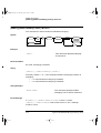
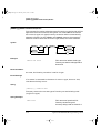
Markings
The CE mark shows that the product complies with
all the relevant European legal Directives (if
accompanied by a year, it signifies when the design
was proven.
ISM
GROUP 1 This is the symbol of an Industrial Scientific and
CLASS A
Medical Group 1 Class A product.
The CSA mark is a registered trademark of the
Canadian Standards Association.
External Protective Earth Terminal.
While this is a Class I product, provided with a
protective earthing conductor in a power cord, an
external protective earthing terminal has also been
provided. This terminal is for use where the earthing
cannot be assured. At least an 18AWG earthing
conductor should be used in such an instance, to
ground the instrument to an assured earth terminal.
vi
Agilent E4418B/E4419B Programming Guide
prog.book Page vii Thursday, June 7, 2001 2:55 PM
General Safety Considerations
IEC 1010-1 Compliance
This instrument has been designed and tested in accordance with IEC
Publication 1010-1 +A1:1992 Safety Requirements for Electrical
Equipment for Measurement, Control and Laboratory Use and has been
supplied in a safe condition. The instruction documentation contains
information and warnings which must be followed by the user to ensure
safe operation and to maintain the instrument in a safe condition.
Statement of Compliance
This product has been designed and tested for compliance with IEC 60529
(1989) Degrees of Protection Provided by Enclosures (IP Code). Level IPx4
is attained if, and only if, the carry case(Agilent part number 34141A) is
fitted.
User Environment
This product is designed for use in a sheltered environment (avoiding
extreme weather conditions) in accordance with Pollution Degree 3
defined in IEC 60664-1, with the carry case (Agilent part number 34141A)
fitted over the instrument.
The product is suitable for indoor use only, when this carry case is not
fitted.
Installation Instructions
To avoid unnecessary over-temperature conditions, while this carry case is
fitted do not apply an ac mains supply voltage, only operate your power
meter from the battery pack.
Agilent E4418B/E4419B Programming Guide
vii
prog.book Page viii Thursday, June 7, 2001 2:55 PM
About this Guide
About this Guide
Chapter 1: Power Meter Remote Operation
This chapter describes the parameters which configure the power meter
and helps you determine settings to optimize performance.
Chapter 2: MEASurement Instructions
This chapter explains how to use the MEASure group of instructions to
acquire data using a set of high level instructions.
Chapter 3: CALCulate Subsystem
This chapter explains how to use the CALCulate subsystem to perform
post acquisition data processing.
Chapter 4: CALibration Subsystem
This chapter explains how to use the CALibration command subsystem
to zero and calibrate the power meter.
Chapter 5: DISPlay Subsystem
This chapter explains how the DISPlay subsystem is used to control the
the selection and presentation of the windows used on the power meter’s
display.
Chapter 6: FORMat Subsystem
This chapter explains how the FORMat subsystem is used to set a data
format for transferring numeric information.
Chapter 7: MEMory Subsystem
This chapter explains how the MEMory command subsystem is used to
create, edit and review sensor calibration tables.
Chapter 8: OUTput Subsystem
This chapter explains how the OUTput command subsystem is used to
switch the POWER REF output on and off.
viii
Agilent E4418B/E4419B Programming Guide
prog.book Page ix Thursday, June 7, 2001 2:55 PM
About this Guide
Chapter 9: SENSe Subsystem
This chapter explains how the SENSe command subsystem directly affects
device specific settings used to make measurements.
Chapter 10: STATus Subsystem
This chapter explains how the STATus command subsystem enables you
to examine the status of the power meter by monitoring the “Device
Status Register”, “Operation Status Register” and the “Questionable
Status Register”.
Chapter 11: SYSTem Subsystem
This chapter explains how to use the SYSTem command subsystem to
return error numbers and messages from the power meter, preset the
power meter, set the GPIB address, set the command language and query
the SCPI version.
Chapter 12: TRIGger Subsystem
This chapter explains how the TRIGger command subsystem is used
synchronize device actions with events.
Chapter 13: UNIT Subsystem
This chapter explains how to use the UNIT command subsystem to set the
power meter measurement units to Watts and % (linear) , or dBm and dB
(logarithmic).
Chapter 14: SERVice Subsystem
This chapter explains how to use the SERVice command subsystem to
obtain and set information useful for servicing the power meter.
Chapter 15: IEEE488.2 Command Reference
This chapter contains information about the IEEE488.2 Common
Commands that the power meter supports.
Agilent E4418B/E4419B Programming Guide
ix
prog.book Page x Thursday, June 7, 2001 2:55 PM
List of Related Publications
List of Related Publications
The Agilent E4418B User’s Guide and the Agilent E4419B User’s Guide
are available in the following languages:
•
English Language User’s Guide - Standard
•
German Language User’s Guide - Option ABD
•
Spanish Language User’s Guide - Option ABE
•
French Language User’s Guide - Option ABF
•
Italian Language User’s Guide - Option ABZ
•
Japanese Language User’s Guide - Option ABJ
Agilent E4418B/E4419B Service Guide is available by ordering Option
915.
Agilent E4418B/E4419B CLIPs (Component Location and Information
Pack) is available by ordering E4418-90031.
Useful information on SCPI (Standard Commands for Programmable
Instruments) can be found in:
x
•
A Beginner’s Guide to SCPI, which is available by ordering
Agilent Part Number 5010-7166.
•
The SCPI reference manuals which are available from:
SCPI Consortium,
8380 Hercules Drive, Suite P3,
La Mesa, CA 91942, USA.
Telephone: 619-697-4301
Fax: 619-697-5955
Agilent E4418B/E4419B Programming Guide
prog.book Page 1 Thursday, June 7, 2001 2:55 PM
Table of Contents
Page
Legal Information ........................................................................ iii
Notice ..................................................................................... iii
Certification ........................................................................... iii
Warranty................................................................................ iii
Limitation of Warranty ......................................................... iv
Exclusive Remedies ............................................................... iv
Equipment Operation ................................................................... v
Personal Safety Considerations............................................. v
General Safety Considerations.................................................... vi
Markings ................................................................................ vi
IEC 1010-1 Compliance........................................................ vii
Statement of Compliance ..................................................... vii
User Environment ................................................................ vii
Installation Instructions ...................................................... vii
About this Guide ........................................................................ viii
List of Related Publications ......................................................... x
Power Meter Remote Operation...................................................... 1-1
Introduction................................................................................... 1-2
Configuring the Remote Interface................................................ 1-3
Interface Selection.................................................................. 1-3
GP-IB Address ........................................................................ 1-3
RS232/RS422 Configuration .................................................. 1-4
Programming Language Selection ....................................... 1-4
Zeroing and Calibrating the Power Meter................................... 1-11
Zeroing .................................................................................... 1-11
Calibration .............................................................................. 1-11
Setting the Reference Calibration Factor ............................. 1-13
Making Measurements ................................................................. 1-14
Using MEASure? .................................................................... 1-15
Using the CONFigure Command .......................................... 1-20
Using the Lower Level Commands........................................ 1-29
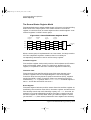
Using Sensor Calibration Tables ................................................. 1-30
Overview ................................................................................. 1-30
Editing Sensor Calibration Tables ........................................ 1-33
Selecting a Sensor Calibration Table .................................... 1-38
Agilent E4418B/E4419B Programming Guide
Contents-1
prog.book Page 2 Thursday, June 7, 2001 2:55 PM
Enabling the Sensor Calibration Table System ................... 1-38
Making the Measurement...................................................... 1-39
Using Frequency Dependent Offset Tables ................................. 1-40
Overview ................................................................................. 1-40
Editing Frequency Dependent Offset Tables........................ 1-42
Selecting a Frequency Dependent Offset Table.................... 1-45
Enabling the Frequency Dependent Offset Table System ... 1-45
Making the Measurement...................................................... 1-46
Setting the Range, Resolution and Averaging ............................ 1-47
Range ...................................................................................... 1-47
Resolution ............................................................................... 1-48
Averaging ................................................................................ 1-48
Setting Offsets............................................................................... 1-51
Channel Offsets ...................................................................... 1-51
Display Offsets........................................................................ 1-51
Example .................................................................................. 1-52
Setting Measurement Limits ....................................................... 1-53
Setting Window Limits .......................................................... 1-55
Checking for Limit Failures................................................... 1-55
Example .................................................................................. 1-57
Measuring Pulsed Signals ............................................................ 1-58
Making the Measurement...................................................... 1-58
Triggering the Power Meter ......................................................... 1-61
Idle State................................................................................. 1-63
Initiate State........................................................................... 1-64
Event Detection State ............................................................ 1-64
Trigger Delay .......................................................................... 1-65
Getting the Best Speed Performance.......................................... 1-66
Speed ....................................................................................... 1-66
Trigger Mode........................................................................... 1-66
Output Format........................................................................ 1-68
Units........................................................................................ 1-68
Command Used ...................................................................... 1-68
200 Readings/Sec .................................................................... 1-68
Dual Channel Considerations................................................ 1-69
How Measurements are Calculated ............................................. 1-70
Status Reporting ........................................................................... 1-71
The General Status Register Model ...................................... 1-72
How to Use Registers ............................................................. 1-74
Status Register ....................................................................... 1-79
Using the Operation Complete Commands .......................... 1-89
Saving and Recalling Power Meter Configurations .................... 1-91
How to Save and Recall a Configuration .............................. 1-91
Contents-2
Agilent E4418B/E4419B Programming Guide
prog.book Page 3 Thursday, June 7, 2001 2:55 PM
Example Program ................................................................... 1-91
Using Device Clear to Halt Measurements ................................. 1-92
An Introduction to the SCPI Language ....................................... 1-93
Syntax Conventions................................................................ 1-95
SCPI Data Types .................................................................... 1-95
Input Message Terminators................................................... 1-101
Quick Reference ............................................................................ 1-102
MEASurement Commands .................................................... 1-103
CALCulate Subsystem ........................................................... 1-104
CALibration Subsystem ......................................................... 1-105
DISPlay Subsystem ................................................................ 1-105
FORMat Subsystem ............................................................... 1-105
MEMory Subsystem ............................................................... 1-106
OUTPut Subsystem................................................................ 1-106
[SENSe] Subsystem................................................................ 1-107
STATus Subsystem ................................................................ 1-108
SYSTem Subsystem ............................................................... 1-109
TRIGger Subsystem ............................................................... 1-109
UNIT Subsystem .................................................................... 1-110
SERVice Subsystem ............................................................... 1-110
SCPI Compliance Information .................................................... 1-111
MEASurement Instructions.............................................................. 2-1
MEASurement Instructions ......................................................... 2-2
CONFigure[1|2]? .......................................................................... 2-6
CONFigure[1|2] Commands........................................................ 2-8
CONFigure[1|2][:SCALar][:POWer:AC]
[<expected_value>[,<resolution>[,<source list>]]] ...................... 2-9
CONFigure[1|2][:SCALar][:POWer:AC]:RELative
[<expected_value>[,<resolution>[,<source list>]]] ...................... 2-11
CONFigure[1|2][:SCALar][:POWer:AC]:DIFFerence
[<expected_value>[,<resolution>[,<source list>]]] ...................... 2-13
CONFigure[1|2][:SCALar][:POWer:AC]:DIFFerence:RELative
[<expected_value>[,<resolution>[,<source list>]]] ...................... 2-15
CONFigure[1|2][:SCALar][:POWer:AC]:RATio
[<expected_value>[,<resolution>[,<source list>]]] ...................... 2-17
CONFigure[1|2][:SCALar][:POWer:AC]:RATio:RELative
[<expected_value>[,<resolution>[,<source list>]]] ...................... 2-19
FETCh[1|2] Queries..................................................................... 2-21
FETCh[1|2][:SCALar][:POWer:AC]? [<expected_value>
[,<resolution>[,<source list>]]] ..................................................... 2-22
FETCh[1|2][:SCALar][:POWer:AC]:RELative?
Agilent E4418B/E4419B Programming Guide
Contents-3
prog.book Page 4 Thursday, June 7, 2001 2:55 PM
[<expected_value>[,<resolution>[,<source list>]]] ...................... 2-24
FETCh[1|2][:SCALar][:POWer:AC]:DIFFerence?
[<expected_value>[,<resolution>[,<source list>]]] ...................... 2-27
FETCh[1|2][:SCALar][:POWer:AC]:DIFFerence:RELative?
[<expected_value>[,<resolution>[,<source list>]]] ...................... 2-29
FETCh[1|2][:SCALar][:POWer:AC]:RATio?
[<expected_value>[,<resolution>[,<source list>]]] ...................... 2-31
FETCh[1|2][:SCALar][:POWer:AC]:RATio:RELative?
[<expected_value>[,<resolution>[,<source list>]]] ...................... 2-33
READ[1|2] Commands................................................................. 2-35
READ[1|2][:SCALar][:POWer:AC]? [<expected_value>
[,<resolution>[,<source list>]]] ..................................................... 2-36
READ[1|2][:SCALar][:POWer:AC]:RELative?
[<expected_value>[,<resolution>[,<source list>]]] ...................... 2-38
READ[1|2][:SCALar][:POWer:AC]:DIFFerence?
[<expected_value>[,<resolution>[,<source list>]]] ...................... 2-41
READ[1|2][:SCALar][:POWer:AC]:DIFFerence:RELative?
[<expected_value>[,<resolution>[,<source list>]]] ...................... 2-43
READ[1|2][:SCALar][:POWer:AC]:RATio? [<expected_value>
[,<resolution>[,<source list>]]] ..................................................... 2-45
READ[1|2][:SCALar][:POWer:AC]:RATio:RELative?
[<expected_value>[,<resolution>[,<source list>]]] ...................... 2-47
MEASure[1|2] Commands........................................................... 2-49
MEASure[1|2][:SCALar][:POWer:AC]? [<expected_value>
[,<resolution>[,<source list>]]] ..................................................... 2-50
MEASure[1|2][:SCALar][:POWer:AC]:RELative?
[<expected_value>[,<resolution>[,<source list>]]] ...................... 2-52
MEASure[1|2][:SCALar][:POWer:AC]:DIFFerence?
[<expected_value>[,<resolution>[,<source list>]]] ...................... 2-54
MEASure[1|2][:SCALar][:POWer:AC]:DIFFerence:RELative?
[<expected_value>[,<resolution>[,<source list>]]] ...................... 2-56
MEASure[1|2][:SCALar][:POWer:AC]:RATio?
[<expected_value>[,<resolution>[,<source list>]]] ...................... 2-58
MEASure[1|2][:SCALar][:POWer:AC]:RATio:RELative?[<expected_value>[,<resolution>[,<source list>]]] .............. 2-60
Contents-4
Agilent E4418B/E4419B Programming Guide
prog.book Page 5 Thursday, June 7, 2001 2:55 PM
CALCulate Subsystem........................................................................ 3-1
CALCulate Subsystem.................................................................. 3-2
The CALCulate[1|2]:GAIN Node ................................................ 3-4
CALCulate[1|2]:GAIN[:MAGNitude] <numeric_value>............ 3-5
CALCulate[1|2]:GAIN:STATe <Boolean> .................................. 3-7
CALCulate[1|2]:LIMit Node ........................................................ 3-8
CALCulate[1|2]:LIMit:CLEar:AUTO <Boolean>|ONCE.......... 3-9
CALCulate[1|2]:Limit:CLEar[:IMMediate] ................................ 3-11
CALCulate[1|2]LIMit:FAIL? ....................................................... 3-12
CALCulate[1|2]:LIMit:FCOunt? ................................................. 3-13
CALCulate[1|2]:LIMit:LOWer[:DATA] <mumeric_value>........ 3-15
CALCulate[1|2]:LIMit:STATe <Boolean> .................................. 3-17
CALCulate[1|2]:LIMit:UPPer[:DATA] <numeric_value>.......... 3-19
The CALCulate[1|2]:MATH Node............................................... 3-21
CALCulate[1|2]:MATH[:EXPRession] <string>......................... 3-22
CALCulate[1|2]:MATH[:EXPRession]:CATalog? ....................... 3-24
The CALCulate[1|2]:RELative Node .......................................... 3-25
CALCulate[1|2]:RELative[:MAGNitude]:AUTO
<Boolean>|ONCE......................................................................... 3-26
CALCulate[1|2]:RELative:STATe <Boolean> ............................ 3-28
CALibration Subsystem..................................................................... 4-1
CALibration Subsystem................................................................ 4-2
CALibration[1|2][:ALL] ............................................................... 4-3
CALibration[1|2][:ALL]?.............................................................. 4-5
CALibration[1|2]:AUTO <Boolean>|ONCE............................... 4-7
CALibration[1|2]:ECONtrol:STATe <Boolean> ......................... 4-9
CALibration[1|2]:RCALibration <Boolean> ............................... 4-10
CALibration[1|2]:RCFactor <numeric_value> ........................... 4-12
CALibration[1|2]:ZERO:AUTO <Boolean>|ONCE ................... 4-14
Agilent E4418B/E4419B Programming Guide
Contents-5
prog.book Page 6 Thursday, June 7, 2001 2:55 PM
DISPlay Subsystem............................................................................. 5-1
DISPlay Subsystem ...................................................................... 5-2
DISPlay:CONTrast <numeric_value> ......................................... 5-3
DISPlay:ENABle <Boolean> ........................................................ 5-5
DISPlay[:WINDow[1|2]] Node..................................................... 5-6
DISPlay[:WINDow[1|2]]:FORMat <character_data> ................ 5-7
DISPlay[:WINDow[1|2]]:METer Node........................................ 5-9
DISPlay[:WINDow[1|2]]:METer:LOWer <numeric_value> ...... 5-10
DISPlay[:WINDow[1|2]]:METer:UPPer <numeric_value> ....... 5-12
DISPlay[:WINDow[1|2]]:RESolution <numeric_value> ............ 5-14
DISPlay[:WINDow[1|2]]:SELect ................................................. 5-16
DISPlay[:WINDow[1|2]][:STATe] <Boolean>............................. 5-17
FORMat Subsystem ............................................................................ 6-1
FORMat Subsystem...................................................................... 6-2
FORMat[:READings]:BORDer NORMal|SWAPped .................. 6-3
FORMat[:READings][:DATA] <Type>......................................... 6-4
MEMory Subsystem ............................................................................ 7-1
MEMory Subsystem...................................................................... 7-2
MEMory:CATalog Node................................................................ 7-3
MEMory:CATalog[:ALL]? ............................................................. 7-4
MEMory:CATalog:STATe? ........................................................... 7-6
MEMory:CATalog:TABLe? ........................................................... 7-7
MEMory:CLEar Node ................................................................... 7-9
MEMory:CLEar[:NAME] <string> .............................................. 7-10
MEMory:CLEar:TABLe................................................................ 7-11
The MEMory:FREE Node............................................................. 7-12
MEMory:FREE[:ALL]? ................................................................. 7-13
MEMory:FREE:STATe? ............................................................... 7-14
MEMory:FREE:TABLe? ............................................................... 7-15
MEMory:NSTates?........................................................................ 7-16
The MEMory:STATe Node ........................................................... 7-17
MEMory:STATe:CATalog? ........................................................... 7-18
MEMory:STATe:DEFine <string>,<numeric_value> ................. 7-19
MEMory:TABLe Node .................................................................. 7-21
MEMory:TABLe:FREQuency <numeric_value>
{,<numeric_value>} ....................................................................... 7-22
MEMory:TABLe:FREQuency:POINts?........................................ 7-25
MEMory:TABLe:GAIN[:MAGNitude]
<numeric_value>{,<numeric_value>} .......................................... 7-26
Contents-6
Agilent E4418B/E4419B Programming Guide
prog.book Page 7 Thursday, June 7, 2001 2:55 PM
MEMory:TABLe:GAIN[:MAGNitude]:POINts? .......................... 7-28
MEMory:TABLe:MOVE <string>,<string> ................................. 7-29
MEMory:TABLe:SELect <string>................................................ 7-30
OUTput Subsystem ............................................................................. 8-1
OUTPut Subsystem ...................................................................... 8-2
OUTPut:ROSCillator[:STATe] <Boolean> .................................. 8-3
OUTPut:TTL[1|2]:ACTive HIGH|LOW ..................................... 8-4
OUTPut:TTL[1|2]:FEED <string> .............................................. 8-5
OUTPut:TTL[1|2]:STATe <Boolean> ......................................... 8-7
SENSe Subsystem................................................................................ 9-1
[SENSe] Subsystem ...................................................................... 9-2
[SENSe[1]]|SENSe2:AVERage Node .......................................... 9-4
[SENSe[1]]|SENSe2:AVERage:COUNt <numeric_value> ........ 9-5
[SENSe[1]]|SENSe2:AVERage:COUNt:AUTO
<Boolean>|ONCE......................................................................... 9-7
[SENSe[1]]|SENSe2:AVERage:SDETect <Boolean> ................. 9-10
[SENSe[1]]|SENSe2:AVERage[:STATe] <Boolean> .................. 9-12
[SENSe[1]]|SENSe2:CORRection Node...................................... 9-13
[SENSe[1]]|SENSe2:CORRection:CSET[1]|CSET2 Node ........ 9-14
[SENSe[1]]|SENSe2:CORRection:CSET[1]|CSET2[:SELect]
<string> ......................................................................................... 9-15
[SENSe[1]]|SENSe2:CORRection:CSET[1]|CSET2:STATe
<Boolean> ...................................................................................... 9-17
[SENSe[1]]|SENSe2:CORRection:DCYCle|GAIN3 Node ......... 9-19
[SENSe[1]]|SENSe2:CORRection:DCYCle|GAIN3[:INPut]
[:MAGNitude] <numeric_value> .................................................. 9-20
[SENSe[1]]|SENSe2:CORRection:DCYCle|GAIN3:STATe
<Boolean> ...................................................................................... 9-23
[SENSe[1]]|SENSe2:CORRection:GAIN[1|2] Node .................. 9-25
[SENSe[1]]|SENSe2:CORRection:CFACtor|GAIN[1|2][:INPut][:MAGNitude] <numeric_value>........................................... 9-26
[SENSe[1]]|SENSe2:CORRection:GAIN2:STATe <Boolean> ... 9-29
[SENSe[1]]|SENSe2:CORRection:FDOFfset|GAIN4[:INPut]
[:MAGNitude]? .............................................................................. 9-31
[SENSe[1]]|SENSe2:CORRection:LOSS2 Node ......................... 9-32
[SENSe[1]]|SENSe2:CORRection:LOSS2[:INPut]
[:MAGNitude] <numeric_value> .................................................. 9-33
[SENSe[1]]|SENSe2:CORRection:LOSS2:STATe <Boolean> ... 9-35
[SENSe[1]]|SENSe2:FREQuency[:CW|:FIXed
] <numeric_value> ........................................................................ 9-37
The [SENSe[1]]|SENSe2:LIMit:CLEar Node ............................. 9-39
[SENSe[1]]|SENSe2:LIMit:CLEar:AUTO
Agilent E4418B/E4419B Programming Guide
Contents-7
prog.book Page 8 Thursday, June 7, 2001 2:55 PM
<Boolean>|ONCE......................................................................... 9-40
[SENSe[1]]|SENSe2:LIMit:CLEar[:IMMediate] ........................ 9-42
[SENSe[1]]|SENSe2:LIMit:FAIL? .............................................. 9-43
[SENSe[1]]|SENSe2:LIMit:FCOunt?.......................................... 9-44
[SENSe[1]]|SENSe2:LIMit:LOWer[:DATA]
<numeric_value> .......................................................................... 9-46
[SENSe[1]]|SENSe2:LIMit:STATe <Boolean> ........................... 9-48
[SENSe[1]]|SENSe2:LIMit:UPPer[:DATA]
<numeric_value> .......................................................................... 9-49
[SENSe[1]]|SENSe2:POWer:AC:RANGe <numeric_value>...... 9-51
[SENSe[1]]|SENSe2:POWer:AC:RANGe:AUTO <Boolean> ..... 9-52
[SENSe[1]]|SENSe2:SPEed <numeric_value>........................... 9-54
[SENSe[1]]|SENSe2:V2P ATYPe|DTYPe .................................. 9-56
STATus Subsystem ........................................................................... 10-1
STATus Subsystem ..................................................................... 10-2
Status Register Set Commands ................................................. 10-4
Device Status Register Sets ....................................................... 10-8
Operation Register Sets.............................................................. 10-10
STATus:OPERation .................................................................... 10-11
STATus:OPERation:CALibrating[:SUMMary] ......................... 10-12
STATus:OPERation:LLFail[:SUMMary]................................... 10-13
STATus:OPERation:MEASuring[:SUMMary] .......................... 10-14
STATus:OPERation:SENSe[:SUMMary] .................................. 10-15
STATus:OPERation:TRIGger[:SUMMary] ............................... 10-16
STATus:OPERation:ULFail[:SUMMary] .................................. 10-17
STATus:PRESet .......................................................................... 10-18
Questionable Register Sets ........................................................ 10-19
STATus:QUEStionable ............................................................... 10-20
STATus:QUEStionable:CALibration[:SUMMary] .................... 10-21
STATus:QUEStionable:POWer[:SUMMary] ............................. 10-22
Contents-8
Agilent E4418B/E4419B Programming Guide
prog.book Page 9 Thursday, June 7, 2001 2:55 PM
SYSTem Subsystem........................................................................... 11-1
SYSTem Subsystem .................................................................... 11-2
SYSTem:COMMunicate:GPIB[:SELF]:ADDRess
<numeric_value>......................................................................... 11-3
SYStem:COMMunicate:Serial Node .......................................... 11-4
SYSTem:COMMunicate:SERial:CONTrol
:DTR ON|OFF|IBFull ............................................................... 11-5
SYSTem:COMMunicate:SERial:CONTrol
:RTS ON|OFF|IBFull................................................................ 11-6
SYSTem:COMMunicate:SERial[:RECeive]:BAUD
<numeric_value>......................................................................... 11-7
SYSTem:COMMunicate:SERial[:RECeive]:BITs
<numeric_value>......................................................................... 11-9
SYSTem:COMMunicate:SERial[:RECeive]
:PACE XON|NONE.................................................................... 11-11
SYSTem:COMMunicate:SERial[:RECeive]:PARity[:TYPE]
EVEN|ODD|ZERO|ONE|NONE ............................................ 11-12
SYSTem:COMMunicate:SERial[:RECeive]:SBITs
<numeric_value>......................................................................... 11-14
SYSTem:COMMunicate:SERial:TRANsmit:AUTO?................. 11-15
SYSTem:COMMunicate:SERial:TRANsmit:BAUD
<numeric_value>......................................................................... 11-16
SYSTem:COMMunicate:SERial:TRANsmit:BITs
<numeric_value>......................................................................... 11-18
SYSTem:COMMunicate:SERial:TRANsmi
t:ECHO ON|OFF........................................................................ 11-19
SYSTem:COMMunicate:SERial:TRANsmit
:PACE XON|NONE.................................................................... 11-21
SYSTem:COMMunicate:SERial:TRANsmit:PARity[:TYPE]
EVEN|ODD|ZERO|ONE|NONE ............................................ 11-22
SYSTem:COMMunicate:SERial:TRANsmit:SBITs
<numeric_value>......................................................................... 11-24
SYSTem:ERRor? ......................................................................... 11-26
SYSTem:LANGuage <character_data> ..................................... 11-27
SYStem:LOCal ............................................................................ 11-28
SYSTem:PRESet ......................................................................... 11-29
SYSTem:REMote ........................................................................ 11-32
SYSTem:RINTerface GPIB|RS232|RS422 .............................. 11-33
SYSTem:RWLock ........................................................................ 11-34
SYSTem:VERSion? ..................................................................... 11-35
Agilent E4418B/E4419B Programming Guide
Contents-9
prog.book Page 10 Thursday, June 7, 2001 2:55 PM
TRIGger Subsystem .......................................................................... 12-1
TRIGger Subsystem.................................................................... 12-2
ABORt[1|2] ................................................................................. 12-3
INITiate Node ............................................................................. 12-4
INITiate[1|2]:CONTinuous <Boolean>..................................... 12-5
INITiate[1|2][:IMMediate] ........................................................ 12-7
TRIGger Node ............................................................................. 12-8
TRIGger[1|2]:DELay:AUTO <Boolean> ................................... 12-9
TRIGger[1|2][:IMMediate] ........................................................ 12-11
TRIGger[1|2]:SOURce BUS|IMMediate|HOLD..................... 12-12
UNIT Subsystem ................................................................................ 13-1
UNIT Subsystem......................................................................... 13-2
UNIT[1|2]:POWer <amplitude_unit> ....................................... 13-3
UNIT[1|2]:POWer:RATio <ratio_unit> .................................... 13-6
SERVice Subsystem .......................................................................... 14-1
SERVice Subsystem.................................................................... 14-2
SERVice:OPTion <string> .......................................................... 14-3
SERVice:SENSor[1|2]:CDATE? ................................................ 14-4
SERVice:SENSor[1|2]:CPLace? ................................................ 14-5
SERVice:SENSor[1|2]:SNUMber? ............................................ 14-6
SERVice:SENSor[1|2]:TYPE? ................................................... 14-7
SERVice:SNUMber <alpha_numeric>....................................... 14-8
SERVice:VERSion:PROCessor <string> ................................... 14-9
SERVice:VERSion:SYSTem <string> ........................................ 14-10
IEEE488.2 Command Reference .................................................... 15-1
IEEE-488 Compliance Information ........................................... 15-2
Universal Commands ................................................................. 15-3
DCL ....................................................................................... 15-3
GET ....................................................................................... 15-3
GTL ....................................................................................... 15-3
LLO ....................................................................................... 15-4
PPC........................................................................................ 15-4
PPD ....................................................................................... 15-4
PPE........................................................................................ 15-4
PPU ....................................................................................... 15-5
SDC ....................................................................................... 15-5
SPD ....................................................................................... 15-6
SPE........................................................................................ 15-6
*CLS ............................................................................................ 15-7
*DDT <arbitrary block program data>|
<string program data> ............................................................... 15-8
Contents-10
Agilent E4418B/E4419B Programming Guide
prog.book Page 11 Thursday, June 7, 2001 2:55 PM
*ESE <NRf> ................................................................................ 15-10
*ESR?........................................................................................... 15-11
*IDN? ........................................................................................... 15-12
*OPC ............................................................................................ 15-13
*OPT? .......................................................................................... 15-14
*RCL <NRf> ................................................................................ 15-15
*RST ............................................................................................ 15-16
*SAV <NRf> ................................................................................ 15-17
*SRE <NRf> ................................................................................ 15-18
*STB? ........................................................................................... 15-20
*TRG ............................................................................................ 15-22
*TST? ........................................................................................... 15-23
*WAI ............................................................................................ 15-24
Agilent E4418B/E4419B Programming Guide
Contents-11
prog.book Page 12 Thursday, June 7, 2001 2:55 PM
Contents-12
Agilent E4418B/E4419B Programming Guide
prog.book Page 13 Thursday, June 7, 2001 2:55 PM
List of Figures
Page
1-1
1-2
1-3
1-4
1-5
1-6
1-7
1-8
1-9
1-10
1-11
1-12
3-1
9-1
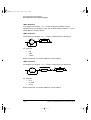
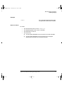
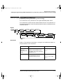
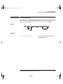
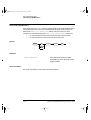
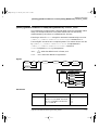
Sensor Calibration Tables ......................................................... 1-31
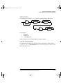
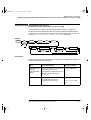
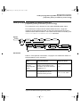
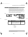
Frequency Dependent Offset Tables......................................... 1-41
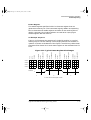
Averaged Readings .................................................................... 1-49
Averaging Range Hysteresis ..................................................... 1-49
Limits Checking Application..................................................... 1-53
Limits Checking Results ........................................................... 1-54
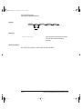
Pulsed Signal ............................................................................. 1-58
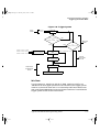
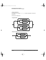
Trigger System........................................................................... 1-63
How Measurements are Calculated.......................................... 1-70
Generalized Status Register Model .......................................... 1-72
Typical Status Register Bit Changes........................................ 1-73
Status System ............................................................................ 1-79
CALCulate Block ....................................................................... 3-3
Averaged Readings .................................................................... 9-7
Agilent E4418B/E4419B Programming Guide
Contents-13
prog.book Page 14 Thursday, June 7, 2001 2:55 PM
Contents-14
Agilent E4418B/E4419B Programming Guide
prog.book Page 15 Thursday, June 7, 2001 2:55 PM
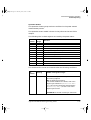
List of Tables
Page
1-1
1-2
1-3
1-4
1-5
1-6
3-1
3-2
5-1
5-2
10-1
11-1
15-1
15-2
15-3
15-4
15-5
15-6
HP 437B Command Summary.................................................. 1-6
HP 438A Command Summary................................................. 1-9
MEASure? and CONFigure Preset States ............................... 1-14
Range of Values for Window Limits ......................................... 1-55
Bit Definitions - Status Byte Register ...................................... 1-80
Bit Definitions - Standard Event Register ............................... 1-82
Measurement Units ................................................................... 3-15
Measurement Units ................................................................... 3-19
Measurement Units ................................................................... 5-10
Measurement Units ................................................................... 5-12
Status Data Structure ............................................................. 10-2
Preset Settings......................................................................... 11-29
PPD Mapping ........................................................................... 15-4
PPE Mapping ........................................................................... 15-5
*ESE Mapping ......................................................................... 15-10
*ESR? Mapping........................................................................ 15-11
*SRE Mapping ......................................................................... 15-18
*STB? Mapping........................................................................ 15-20
Agilent E4418B/E4419B Programming Guide
Contents-15
prog.book Page 16 Thursday, June 7, 2001 2:55 PM
Contents-16
Agilent E4418B/E4419B Programming Guide
prog.book Page 1 Thursday, June 7, 2001 2:55 PM
1
Power Meter Remote Operation
prog.book Page 2 Thursday, June 7, 2001 2:55 PM
Power Meter Remote Operation
Introduction
Introduction
This chapter describes the parameters which configure the power meter
and help you determine settings to optimize performance. It contains the
following sections:
“Configuring the Remote Interface”, on page 1-3.
“Zeroing and Calibrating the Power Meter”, on page 1-11.
“Making Measurements”, on page 1-14.
“Using Sensor Calibration Tables”, on page 1-30.
“Using Frequency Dependent Offset Tables”, on page 1-40
“Setting the Range, Resolution and Averaging”, on page 1-47.
“Setting Offsets”, on page 1-51.
“Setting Measurement Limits”, on page 1-53.
“Measuring Pulsed Signals”, on page 1-58.
“Triggering the Power Meter”, on page 1-61.
“Getting the Best Speed Performance”, on page 1-66.
“How Measurements are Calculated”, on page 1-70.
“Status Reporting”, on page 1-71.
“Saving and Recalling Power Meter Configurations”, on page 1-91.
“Using Device Clear to Halt Measurements”, on page 1-92.
“An Introduction to the SCPI Language”, on page 1-93.
“Quick Reference”, on page 1-102.
“SCPI Compliance Information”, on page 1-111.
1-2
Agilent E4418B/E4419B Programming Guide
prog.book Page 3 Thursday, June 7, 2001 2:55 PM
Power Meter Remote Operation
Configuring the Remote Interface
Configuring the Remote Interface
This section describes how to configure the GP-IB, RS232 and RS422
remote interfaces.
Interface Selection
You can choose to control the power meter remotely using either the
GP-IB, RS232 or RS422 standard interfaces.
For information on selecting the remote interface manually from the front
panel, refer to the Agilent Technologies E4418B/E4419B User’s Guides.
To select the interface remotely use the :
•
SYSTem:RINTerface command
To query the current remote interface selection use the:
•
SYSTem:RINTerface? command
GP-IB Address
Each device on the GP-IB (IEEE-488) interface must have a unique
address. You can set the power meter’s address to any value between 0
and 30. The address is set to 13 when the power meter is shipped from the
factory.
The address is stored in non-volatile memory, and does not change when
the power meter is switched off, or after a remote interface reset.
Your GP-IB bus controller has its own address. Avoid using the bus
controller’s address for any instrument on the interface bus.
Hewlett-Packard controllers generally use address 21.
For information on setting the GP-IB address manually from the front
panel, refer to the Agilent Technologies E4418B/E4419B User’s Guides.
To set the GP-IB address from the remote interface use the:
•
SYSTem:COMMunicate:GPIB:ADDRess command.
To query the GP-IB address from the remote interface use the;
•
SYSTem:COMMunicate:GPIB:ADDRess? query.
Agilent E4418B/E4419B Programming Guide
1-3
prog.book Page 4 Thursday, June 7, 2001 2:55 PM
Power Meter Remote Operation
Configuring the Remote Interface
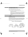
RS232/RS422 Configuration
The RS232/RS422 serial port on the rear panel is a nine pin D-type
connector configured as a DTE (Data Terminal Equipment). For pin-out
information and cable length restrictions refer to the Agilent Technologies
E4418A/E4419B User’s Guides.
You can set the baud rate, word length, parity, number of stop bits,
software and hardware pacing, either remotely or from the front panel.
For front panel operation refer to the Agilent Technologies
E4418A/E4419B User’s Guides. For remote operation use the following
commands:
SYSTem:COMMunicate:SERial:CONTrol:DTR
SYSTem:COMMunicate:SERial:CONTrol:RTS
SYSTem:COMMunicate:SERial[:RECeive]:BAUD
SYSTem:COMMunicate:SERial[:RECeive]:BITs
SYSTem:COMMunicate:SERial[:RECeive]:PACE
SYSTem:COMMunicate:SERial[:RECeive]:PARity[:TYPE]
SYSTem:COMMunicate:SERial[:RECeive]:SBIT
SYSTem:COMMunicate:SERial:TRANsmit:BAUD
SYSTem:COMMunicate:SERial:TRANsmit:BIT
SYSTem:COMMunicate:SERial:TRANsmit:ECHO
SYSTem:COMMunicate:SERial:TRANsmit:PACE
SYSTem:COMMunicate:SERial:TRANsmit:PARity[:TYPE]
SYSTem:COMMunicate:SERial:TRANsmit:SBIT
Programming Language Selection
You can select one of two languages to program the power meter from the
remote interface. The language is SCPI when the power meter is shipped
from the factory. The other language depends on the model number of your
power meter:
•
For E4418B the language is 437B programming language.
•
For E4419B the language is 438A programming language.
The language selection is stored in non-volatile memory, and does not
change when power has been off, or after either a remote interface reset,
or a front panel preset.
For information on selecting the interface language manually from the
front panel, refer to the Agilent Technologies E4418B/E4419B User’s
Guides.
1-4
Agilent E4418B/E4419B Programming Guide
prog.book Page 5 Thursday, June 7, 2001 2:55 PM
Power Meter Remote Operation
Configuring the Remote Interface
To select the interface language from the remote interface use the:
•
SYSTem:LANGuage command.
To query the interface language from the remote interface use the:
•
SYSTem:LANGuage? query.
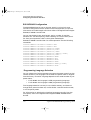
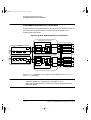
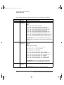
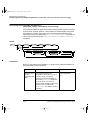
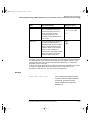
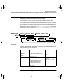
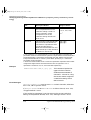
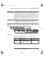
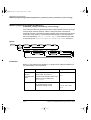
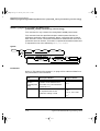
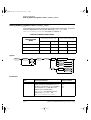
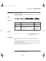
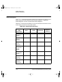
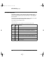
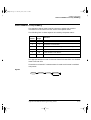
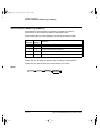
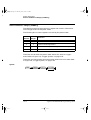
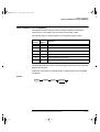
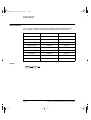
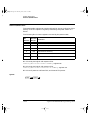
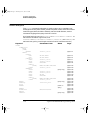
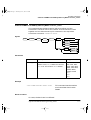
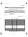
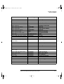
Table 1-1 details all the HP 437B commands that the Agilent E4418B
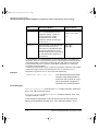
supports and their function, and Table 1-2 details all the HP 438A
commands that the Agilent E4419B supports and their function. For a
detailed description of these commands refer to the HP 437B Power Meter
Operating Manual (E4418B users), or the HP 438A Operating and Service
Manual (E4419B users). In addition, the SYST:LANG SCPI command
allows you to return to using the SCPI programming language when in
the HP 437B or HP 438A mode. Note that the 437B commands only
operate on the upper window of the E4418B.
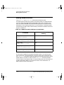
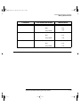
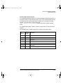
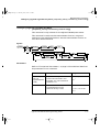
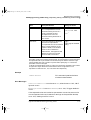
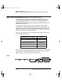
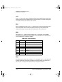
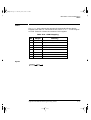
437B/438A Error Codes
If an overrun error, parity error, or framing error occurs, then the status
message will return the following additional error codes to those outlined
in the 437B and 438A Operating Manuals.:
Error Code
Description
94
Receiver overrun error
95
Parity error
96
Framing error
Agilent E4418B/E4419B Programming Guide
1-5
prog.book Page 6 Thursday, June 7, 2001 2:55 PM
Power Meter Remote Operation
Configuring the Remote Interface
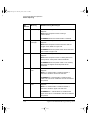
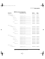
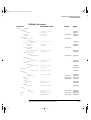
Table 1-1: HP 437B Command Summary
Command
CL
*CLS
CS
Calibrate
Clear all status registers
Clear the status byte
CT
DA 1
DC0
Clear sensor table
DC1
DD
DE
Duty Cycle on
DF
DN1
DU1
DY
Display enable
EN
Enter
ERR?
*ESR?
*ESE
*ESE?
All display segments on
Duty Cycle off
Display disable
Display enable
Down arrow key
Display user message
Enter duty cycle
Device error query
Event status register query
Set event status register mask
Event status register mask query
ET
Edit sensor table
EX
Exit
FA
Automatic filter selection
FH
Filter hold
FM
Manual filter selection
FR
Enter measurement frequency
GT0
Ignore GET bus command
GT1
Trigger immediate response to GET
GT2
Trigger with delay response to GET
GZ
Gigahertz
HZ
Hertz
ID
Identification query
IDN?
Identification query
KB
1-6
Description
Enter measurement cal factor
Agilent E4418B/E4419B Programming Guide
prog.book Page 7 Thursday, June 7, 2001 2:55 PM
Power Meter Remote Operation
Configuring the Remote Interface
Command
Description
KZ
Kilohertz
LG
Log units (dBm/dB)
LH
Enter high (upper) limit
LL
Enter low (lower) limit
LM0
Disable limits checking
LM1
Enable limits checking
LN
Linear units (watts/%)
LP2
LT 1
MZ
Learn mode
OC0
Reference oscillator off
OC1
Reference oscillator on
OD
Left arrow key
Megahertz
Output display
OF0
Offset off
OF1
Offset on
OS
Enter offset value
PCT
Percent
PR
Preset
RA
Auto range
RC
Recall instrument configuration
RE
Set display resolution
RF
Enter sensor table reference calibration factor
RH
Range hold
RL0
Exit from relative mode
RL1
Enter relative mode (take new reference)
RL2
Enter relative mode (use last reference)
RM
*RST
RT 1
RV
Set measurement range
Reset
Right arrow key
Read service request mask
SE
Select sensor calibration table
SM
Status message
SN
Enter sensor identification/serial number
Agilent E4418B/E4419B Programming Guide
1-7
prog.book Page 8 Thursday, June 7, 2001 2:55 PM
Power Meter Remote Operation
Configuring the Remote Interface
Command
Description
1
Special
SP
SPD 20|402
20 or 40 readings/sec
*SRE
Set the service request mask
*SRE?
Service request mask query
Store (save) power meter configuration
ST
*STB?
SYST:LANG SCPI
TK?4
TR0
Read status byte
3
Selects SCPI language
Last measurement result transmitted
Trigger hold
TR1
Trigger immediate
TR2
Trigger with delay
TR3
Trigger free run
*TST?5
1
Self test query
UP
ZE
Up arrow key
@1
Prefix for status mask
@2
Learn mode prefix
%
Zero
Percent
1. This command is accepted but has no active function.
2. This command is not an original HP 437B command. However, it can be used to
set the measurement speed to 20 or 40 readings/sec in HP 437B mode. See
SENSE:SPEED for more details.
3. This command is not an original HP 437B command. However, it can be used to
terminate the HP 437B language and select the SCPI language. Note that it is
recommended that the instrument is Preset following a language switch.
4. This command is not an original HP 437B command. However, it can be used to
allow the last measurement result to be transmitted. This is equivalent to
sending the power meter talk address in GP-IB mode to fetch the last reading
(provided no query is pending).
5. Always returns 0000 in HP 437B language.
1-8
Agilent E4418B/E4419B Programming Guide
prog.book Page 9 Thursday, June 7, 2001 2:55 PM
Power Meter Remote Operation
Configuring the Remote Interface
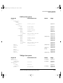
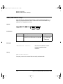
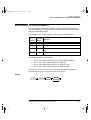
Table 1-2: HP 438A Command Summary
Command
Description
AD
Sensor A minus Sensor B measurement
AE
SET A
AP
Sensor A measurement
AR
A/B ratio measurement
BD
Sensor B minus Sensor A measurement
BE
SET B
BP
Sensor B measurement
BR
B/A ratio measurement
CL
Calibrate
CS
DA 1
DD
Clear the status byte
All display segments on
Display disable
DE
Display enable
DO
Display offset
EN
Enter
FA
Automatic filter selection
FH
Filter hold
FM
Manual filter selection
FR
Enter measurement frequency
GT0
Ignore GET bus command
GT1
Trigger immediate response to GET
GT2
Trigger with delay response to GET
KB
Enter measurement cal factor
LG
Log units (dBm/dB)
LH
Enter high (upper) limit
LL
Enter low (lower) limit
LM0
Disable limits checking
LM1
Enable limits checking
LN
Linear units (watts/%)
LP1
Learn mode #1
LP2
Learn mode #2
OC0
Reference oscillator off
Agilent E4418B/E4419B Programming Guide
1-9
prog.book Page 10 Thursday, June 7, 2001 2:55 PM
Power Meter Remote Operation
Configuring the Remote Interface
Command
Description
Reference oscillator on
OC1
SPD
OS
Enter offset value
PR
Preset
RA
Auto range
RC
Recall instrument configuration
RH
Range hold
RL0
Exit from relative mode
RL1
Enter relative mode (take new reference)
RM
Set measurement range
RV
Read service request mask
SM
Status message
20|402
20 or 40 readings/sec
ST
SYST:LANG SCPI
TK?4
TR0
Store (save) power meter configuration
3
Selects SCPI language
Last measurement result transmitted
Trigger hold
TR1
Trigger immediate
TR2
Trigger with delay
TR3
Trigger free run
ZE
Zero
@1
Prefix for status mask
?ID
Identification query
1. This command is accepted but has no active function.
2. This command is not an original HP 438A command. However, it can be used to
set the measurement speed to 20 or 40 readings/sec in HP 438A mode. See
SENSE:SPEED for more details.
3. This command is not an original HP 438A command. However, it can be used to
terminate the HP 438A language and select the SCPI language. Note that it is
recommended that the instrument is Preset following a language switch.
4. This command is not an original HP 437B command. However, it can be used to
allow the last measurement result to be transmitted. This is equivalent to
sending the power meter talk address in GP-IB mode to fetch the last reading
(provided no query is pending).
1-10
Agilent E4418B/E4419B Programming Guide
prog.book Page 11 Thursday, June 7, 2001 2:55 PM
Power Meter Remote Operation
Zeroing and Calibrating the Power Meter
Zeroing and Calibrating the Power Meter
This section describes how to zero and calibrate the power meter.
The calibration and zeroing commands are overlapped commands refer to
“Using the Operation Complete Commands”, on page 1-89 to determine
when the commands are complete.
Zeroing
Zeroing adjusts the power meter’s specified channel for a zero power
reading with no power applied to the power sensor.
The command used to zero the power meter is:
CALibration[1|2]:ZERO:AUTO ONCE
The command assumes that there is no power being applied to the sensor.
It turns the power reference oscillator off, then after zeroing, returns the
power reference oscillator to the same state it was in prior to the command
being received. Zeroing takes approximately 10 seconds depending on the
type of power sensor being used.
When to Zero?
Zeroing of the power meter is recommended:
•
when a 50C change in temperature occurs.
•
when you change the power sensor.
•
every 24 hours.
•
prior to measuring low level signals. For example, 10 dB above the
lowest specified power for your power sensor.
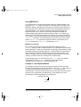
Calibration
Calibration sets the gain of the power meter using a 50 MHz 1 mW
calibrator as a traceable power reference. The power meter’s POWER REF
output or a suitable external reference is used as the signal source for
calibration. An essential part of calibrating is setting the correct reference
calibration factor for the power sensor you are using. The Agilent 8480
series power sensors require you to set the reference calibration factor.
The Agilent E-series power sensors set the reference calibration factor
Agilent E4418B/E4419B Programming Guide
1-11
prog.book Page 12 Thursday, June 7, 2001 2:55 PM
Power Meter Remote Operation
Zeroing and Calibrating the Power Meter
automatically. Offset, relative and duty cycle settings are ignored during
calibration.
The command used to calibrate the power meter is:
CALibration[1|2]:AUTO ONCE
The command assumes that the power sensor is connected to a 1 mW
reference signal. It turns the power reference oscillator on, then after
calibrating, returns the power reference oscillator to the same state it was
in prior to the command being received. It is recommended that you zero
the power meter before calibrating.
Calibration Sequence
This feature allows you to perform a complete calibration sequence with a
single query. The query is:
CALibration[1|2][:ALL]?
The query assumes that the power sensor is connected to the power
reference oscillator. It turns the power reference oscillator on, then after
calibrating, returns the power reference oscillator to the same state it was
in prior to the command being received. The calibration sequence consists
of:
•
Zeroing the power meter (CALibration[1|2]:ZERO:AUTO
ONCE), and
•
calibrating the power meter (CALibration[1|2]:AUTO ONCE).
The query enters a number into the output buffer when the sequence is
complete. If the result is 0 the sequence was successful. If the result is 1
the sequence failed. Refer to “CALibration[1|2][:ALL]?”, on page 4-5 for
further information.
Note
The CALibration[1|2][:ALL] command is identical to the
CALibration[1|2][:ALL]? query except that no number is
returned to indicate the outcome of the sequence. You can examine
the Questionable Status Register or the error queue to discover if
the sequence has passed or failed. Refer to “Status Reporting”, on
page 1-71 for further information.
1-12
Agilent E4418B/E4419B Programming Guide
prog.book Page 13 Thursday, June 7, 2001 2:55 PM
Power Meter Remote Operation
Zeroing and Calibrating the Power Meter
Setting the Reference Calibration Factor
All the Agilent 8480 series power sensors require you to set the reference
calibration factor. The reference calibration factor can be set by:
•
entering the value into the power meter using the
CALibrate[1|2]:RCFactor command.
•
selecting and enabling the sensor calibration table. The reference
calibration factor is automatically set by the power meter using
the reference calibration factor stored in the sensor calibration
table. See “Using Sensor Calibration Tables”, on page 1-30 for
further information.
Examples
a) To enter a reference calibration factor of 98.7% for channel A, you
should use the following command :
CAL:RCF 98.7PCT
This overides any RCF previously set by selecting a sensor
calibration table.
b) To automatically set the reference calibration factor, you have to
use a sensor calibration table as described in “Using Sensor
Calibration Tables”, on page 1-30. To select and enable the table
use the following commands:
[SENSe[1]]|SENSe2:CORRection:CSET1:SELect <string>
[SENSe[1]]|SENSe2:CORRection:CSET1:STATe ON
When the sensor calibration table is selected the RCF from the
table overides any value previously set.
Querying the Reference Calibration Factor
To determine the current reference calibration factor, use the following
command:
CALibration[1|2]:RCFactor?
Agilent E4418B/E4419B Programming Guide
1-13
prog.book Page 14 Thursday, June 7, 2001 2:55 PM
Power Meter Remote Operation
Making Measurements
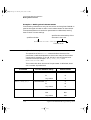
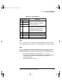
Making Measurements
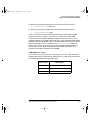
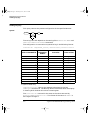
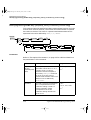
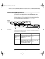
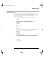
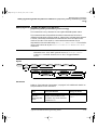
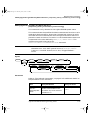
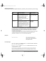
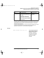
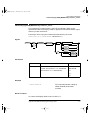
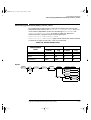
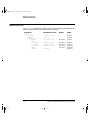
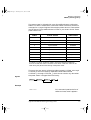
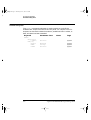
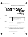
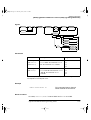
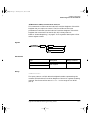
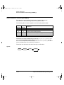
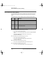
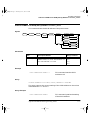
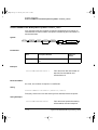
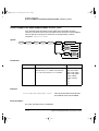
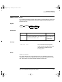
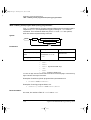
The MEASure? and CONFigure commands provide the most
straight-forward method to program the power meter for measurements.
You can select the measurement’s expected power level, resolution and
with the Agilent E4419B the measurement type (that is single channel,
difference or ratio measurements) all in one command. The power meter
automatically presets other measurement parameters to default values as
shown in Table 1-3.
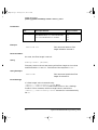
Table 1-3: MEASure? and CONFigure Preset States
Command
MEASure? and CONFigure
Setting
Trigger source
(TRIGger:SOURce)
Immediate
Filter
(SENSe:AVERage:COUNt:AUTO)
On
Filter state
(SENSe:AVERage:STATe)
On
Trigger cycle
(INITiate:CONTinuous)
Off
Trigger Delay
(TRIGger:DELay:AUTO)
On
An alternative method to program the power meter is to use the lower
level commands. The advantage of using the lower level commands over
the CONFigure command is that they give you more precise control of the
power meter. As shown in Table 1-3 the CONFigure command presets
various states in the power meter. It may be likely that you do not want to
preset these states. Refer to “Using the Lower Level Commands”, on
page 1-29 for further information.
1-14
Agilent E4418B/E4419B Programming Guide
prog.book Page 15 Thursday, June 7, 2001 2:55 PM
Power Meter Remote Operation
Making Measurements
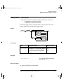
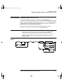
Using MEASure?
The simplest way to program the power meter for measurements is by
using the MEASure? query. However, this command does not offer much
flexibility. When you execute the command, the power meter selects the
best settings for the requested configuration and immediately performs
the measurement. You cannot change any settings (other than the
expected power value, resolution and with the Agilent E4419B the
measurement type) before the measurement is taken. This means you
cannot fine tune the measurement, for example, you cannot change the
filter length. To make more flexible and accurate measurements use the
CONFIGure command. The measurement results are sent to the output
buffer. MEASure? is a compound command which is equivalent to an
ABORT, followed by a CONFigure, followed by a READ?.
MEASure? Examples
The following commands show a few examples of how to use the
MEASure? query to make a measurement. It is advisable to read through
these examples in order as they become increasingly more detailed. These
examples configure the power meter for a measurement (as described in
each individual example), automatically place the power meter in the
“wait-for-trigger” state, internally trigger the power meter to take one
reading, and then sends the reading to the output buffer.
These examples give an overview of the MEASure? query. For further
information on the MEASure? commands refer to the section
“MEASure[1|2] Commands” starting on page 2-49 .
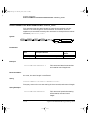
Example 1 - The Simplest Method
The following commands show the simplest method of making single
channel (for example A or B) measurements. Using MEAS1? will result in
an upper window measurement, and MEAS2? in a lower window
measurement. The channel associated with the window can be set using
the source list parameter (see example 2), or will default as in this
example (See “Agilent E4419B only” on page 18.).
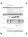
specifies window
MEAS1?
MEAS2?
Agilent E4418B/E4419B Programming Guide
1-15
prog.book Page 16 Thursday, June 7, 2001 2:55 PM
Power Meter Remote Operation
Making Measurements
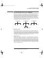
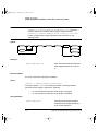
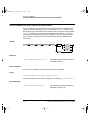
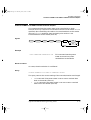
Example 2 - Specifying the Source List Parameter
The MEASure command has three optional parameters, an expected power
value, a resolution and a source list. These parameters must be entered in
the specified order. If parameters are omitted, they will default from the
right. The parameter DEFault is used as a place holder.
The following example uses the source list parameter to specify the
measurement channel as channel A. The expected power and resolution
parameters are defaulted, leaving them at their current settings. The
measurement is carried out on the upper window.
specifies window
specifies channel
MEAS1? DEF,DEF,(@1)
The operation of the MEAS1? command when the source list parameter is
defaulted is described in the note on page 1-18.
Note
For the Agilent E4418B it is not necessary to specify a channel as
only one channel is available.
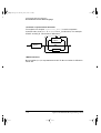
Example 3 - Specifying the Expected Power Parameter
The previous example details the three optional parameters which can be
used with the MEASure? command. The first optional parameter is used to
enter an expected power value. Entering this parameter is only relevant if
you are using an Agilent E-series power sensor. The value entered
determines which of the power sensor’s two ranges is used for the
measurement. If the current setting of the power sensor’s range is no
longer valid for the new measurement, specifying the expected power
value decreases the time taken to obtain a result.
The following example uses the expected value parameter to specify a
value of -50 dBm. This selects the power sensor’s lower range (refer to
“Range”, on page 1-47 for details of the range breaks). The resolution
parameter is defaulted, leaving it at its current setting. The source list
parameter specifies a channel B measurement. The measurement is
displayed on the lower window.
specifies expected power value
specifies window
specifies channel
MEAS2? -50,DEF,(@2)
1-16
Agilent E4418B/E4419B Programming Guide
prog.book Page 17 Thursday, June 7, 2001 2:55 PM
Power Meter Remote Operation
Making Measurements
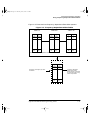
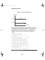
Example 4 - Specifying the Resolution Parameter
The previous examples detailed the use of the expected value and source
list parameters. The resolution parameter is used to set the resolution of
the specified window. This parameter does not affect the resolution of the
GP-IB data, however it does affect the auto averaging setting (refer to
Figure 1-3 on page 1-49).
Since the filter length used for a channel with auto-averaging enabled is
dependent on the window resolution setting, a conflict arises when a given
channel is set up in both windows and the resolution settings are
different. In this case, the higher resolution setting is used to determine
the filter length.
The following example uses the resolution parameter to specify a
resolution setting of 3. This setting represents 3 significant digits if the
measurement suffix is W or %, and 0.01 dB if the suffix is dB or dBm (for
further details on the resolution parameter refer to the commands in
Chapter 2, “MEASurement Instructions”.). Also, in this example the
expected power and source list parameters are defaulted. The expected
power value will be left unchanged at its current setting. The source list
parameter will be defaulted as described in the note on page 1-18. Note
that as the source list parameter is the last specified parameter you do not
have to specify DEF. The measurement is carried out on the upper window.
specifies window
specifies resolution setting
MEAS1? DEF,3
Example 5 - Making a Difference Measurement
The following command can only be carried out on the Agilent E4419B. It
queries the lower window to make a difference measurement of
channel B - channel A . The expected power and resolution parameters
are defaulted, leaving them at their current settings.
specifies window
specifies between which channels
the difference is calculated
MEAS2:POW:AC:DIFF? DEF,DEF,(@2),(@1)
Channel B - A
Agilent E4418B/E4419B Programming Guide
1-17
prog.book Page 18 Thursday, June 7, 2001 2:55 PM
Power Meter Remote Operation
Making Measurements
Example 6 - Making a Ratio Measurement
The following command can only be carried out on the Agilent E4419B. It
queries the upper window to make a ratio measurement of channel A/B .
The expected power and resolution parameters are defaulted, leaving
them at their current settings.
specifies the relationship of the
channels in the ratio
specifies window
MEAS1:POW:AC:RAT? DEF,DEF,(@1),(@2)
Channel A / B
Note
Agilent E4419B only
The operation of the MEASure? command when the source list
parameter is defaulted depends on the current setup of the window
concerned (for example, A, B, A/B, A-B etc.) and on the particular
command used (for example, MEAS[:POW][:AC]? and
MEAS:POW:AC:RAT? etc).
This means that when the source list parameter is defaulted, there
are a number of possibilities.
Command
MEAS1[:POW][AC]?
MEAS2[:POW][AC]?
MEAS1:POW:AC:RAT
1-18
Current Window Setup
Measurement
Upper Window: A
A
B
B
Any Other
A
Lower Window: A
A
B
B
Any Other
B
Upper Window: A/B
A/B
B/A
B/A
Any Other
A/B
Agilent E4418B/E4419B Programming Guide
prog.book Page 19 Thursday, June 7, 2001 2:55 PM
Power Meter Remote Operation
Making Measurements
Command
MEAS2:POW:AC:RAT
MEAS1:POW:AC:DIFF?
MEAS2:POW:AC:DIFF?
Current Window Setup
Measurement
Lower Window: A/B
A/B
B/A
B/A
Any Other
A/B
Upper Window: A-B
A-B
B-A
B-A
Any Other
A-B
Lower Window: A-B
A-B
B-A
B-A
Any Other
A-B
Agilent E4418B/E4419B Programming Guide
1-19
prog.book Page 20 Thursday, June 7, 2001 2:55 PM
Power Meter Remote Operation
Making Measurements
Using the CONFigure Command
When you execute this command, the power meter presets the best
settings for the requested configuration (like the MEASure? query).
However, the measurement is not automatically started and you can
change measurement parameters before making measurements. This
allows you to incrementally change the power meter’s configuration from
the preset conditions. The power meter offers a variety of low-level
commands in the SENSe, CALCulate, and TRIGger subsystems. For
example, if you want to change the averaging use the
[SENSe[1]]|SENSe2:AVERage:COUNt command.
Use the INITiate or READ? query to initiate the measurement.
Using READ?
CONFigure does not take the measurement. One method of obtaining a
result is to use the READ? query. The READ? query takes the measurement
using the parameters set by the CONFigure command then sends the
reading to the output buffer. Using the READ? query will obtain new data.
Using INITiate and FETCh?
CONFigure does not take the measurement. One method of obtaining the
result is to use the INITiate and FETCh? commands. The INITiate
command causes the measurement to be taken. The FETCh? query
retrieves a reading when the measurement is complete, and sends the
reading to the output buffer. FETCh? can be used to display the
measurement results in a number of different formats (for example, A/B
and B/A) without taking fresh data for each measurement.
CONFigure Examples
The following program segments show how to use the READ? command
and the INITiate and FETCh? commands with CONFigure to make
measurements.
It is advisable to read through these examples in order as they become
increasingly more detailed.
These examples give an overview of the CONFigure command. For further
information on the CONFigure commands refer to Chapter 2,
“MEASurement Instructions”.
1-20
Agilent E4418B/E4419B Programming Guide
prog.book Page 21 Thursday, June 7, 2001 2:55 PM
Power Meter Remote Operation
Making Measurements
Example 1 - The Simplest Method
The following program segments show the simplest method of querying
the upper and lower window’s measurement results respectively.
Using READ?
*RST
CONF1
READ1?
*RST
CONF2
READ2?
Reset instrument
Configure upper window - defaults to a channel A
measurement
Take upper window (channel A) measurement
Reset instrument
Configure the lower window - defaults to channel A
(Agilent E4418B), Channel B (Agilent E4419B) measurement
Take lower window measurement (channel A on
Agilent E4418B, B on Agilent E4419B)
Using INITiate and FETCh?
*RST
CONF1
INIT1
FETC1?
Reset instrument
Configure upper window - defaults to a channel A
measurement
Causes channel A to make a measurement
Retrieves the upper window’s measurement
For the Agilent E4418B only:
*RST
CONF2
INIT1?
FETC2?
Reset instrument
Configure lower window - Agilent E4418B defaults to
channel A
Causes channel A to make measurement
Retrieves the lower window’s measurement
For the Agilent E4419B only:
*RST
CONF2
INIT2?
FETC2?
Reset instrument
Configure lower window
Causes channel B to make measurement
Retrieves the lower window’s measurement
Agilent E4418B/E4419B Programming Guide
1-21
prog.book Page 22 Thursday, June 7, 2001 2:55 PM
Power Meter Remote Operation
Making Measurements
Example 2 - Specifying the Source List Parameter
The CONFigure and READ? commands have three optional parameters,
an expected power value, a resolution and a source list. These parameters
must be entered in the specified order. If parameters are omitted, they will
default from the right. The parameter DEFault is used as a place holder.
The following examples use the source list parameter to specify the
measurement channel as channel A. The expected power and resolution
parameters are defaulted, leaving them at their current settings. The
measurement is carried out on the upper window.
Although the READ? and FETCh? queries have three optional parameters
it is not necessary to define them as shown in these examples. If they are
defined they must be identical to those defined in the CONFigure
command otherwise an error occurs.
Note
For the Agilent E4418B it is not necessary to specify a channel as
only one channel is available.
Using READ?
ABOR1
Aborts channel A
CONF1 DEF,DEF,(@1)
Configures the upper window to
make a channel A measurement
using the current expected power
and resolution settings.
READ1?
Takes the upper window’s
measurement.
Using INITiate and FETCh?
ABOR1
Aborts channel A
CONF1 DEF,DEF,(@1)
Configures the upper window to
make a channel A measurement
using the current expected power
and resolution settings.
INIT1
Causes channel A to make a
measurement.
FETC1?
Retrieves the upper window’s
measurement.
1-22
Agilent E4418B/E4419B Programming Guide
prog.book Page 23 Thursday, June 7, 2001 2:55 PM
Power Meter Remote Operation
Making Measurements
Example 3 - Specifying the Expected Power Parameter
The previous example details the three optional parameters which can be
used with the CONFigure and READ? commands. The first optional
parameter is used to enter an expected power value. Entering this
parameter is only relevant if you are using an Agilent E-series power
sensor. The value entered determines which of the power sensor’s two
ranges is used for the measurement. If the current setting of the power
sensor’s range is no longer valid for the new measurement, specifying the
expected power value decreases the time taken to obtain a result.
The following example uses the expected value parameter to specify a
value of -50 dBm. This selects the power meter’s lower range (refer to
“Range”, on page 1-47 for details of the range breaks). The resolution
parameter is defaulted, leaving it at its current setting. The source list
parameter specifies a channel B measurement. The measurement is
carried out on the upper window.
Using READ?
ABOR2
Aborts channel B
CONF1 -50,DEF,(@2)
Configures the upper window to
make a channel B measurement
using an expected power of
-50 dBm and the current
resolution setting.
READ1?
Takes the upper window’s
measurement.
Some fine tuning of measurements can be carried out using the
CONFigure and READ? commands. For example, in the above program
segment some fine tuning can be carried out by setting the filter length to
1024 and the trigger delay off.
ABOR2
CONF1 -50,DEF,(@2)
SENS2:AVER:COUN 1024
TRIG2:DEL:AUTO OFF
READ1?
Agilent E4418B/E4419B Programming Guide
1-23
prog.book Page 24 Thursday, June 7, 2001 2:55 PM
Power Meter Remote Operation
Making Measurements
Using INITiate and FETCh?
ABOR2
Aborts channel B
CONF1 -50,DEF,(@2)
Configures the upperwindow to
make a channel B measurement
using an expected power of
-50 dBm and the current
resolution setting.
INIT2
Causes channel B to make a
measurement.
FETC1?
Retrieves the upper window’s
measurement.
Some fine tuning of measurements can be carried out using the
CONFigure command and INITiate and FETCh? commands. For
example, in the above program segment some fine tuning can be carried
out by setting the filter length to 1024 and the trigger delay off.
ABOR2
CONF1 -50,DEF,(@2)
SENS2:AVER:COUN 1024
TRIG2:DEL:AUTO OFF
INIT2
FETC1?
1-24
Agilent E4418B/E4419B Programming Guide
prog.book Page 25 Thursday, June 7, 2001 2:55 PM
Power Meter Remote Operation
Making Measurements
Example 4 - Specifying the Resolution Parameter
The previous examples detailed the use of the expected value and source
list parameters. The resolution parameter is used to set the resolution of
the specified window. This parameter does not affect the resolution of the
GP-IB data, however it does affect the auto averaging setting (refer to
Figure 1-3 on page 1-49).
Since the filter length used for a channel with auto-averaging enabled is
dependent on the window resolution setting, a conflict arises when a given
channel is set up in both windows and the resolution settings are
different. In this case, the higher resolution setting is used to determine
the filter length.
The following example uses the resolution parameter to specify a
resolution setting of 3. This setting represents 3 significant digits if the
measurement suffix is W or %, and 0.01 dB if the suffix is dB or dBm (for
further details on the resolution parameter refer to the commands in
Chapter 2, “MEASurement Instructions”). Also, in this example the
expected power and source list parameters are defaulted. The expected
power value will be left unchanged at its current setting. The source list
parameter will be defaulted as described in the note on page 1-18. Note
that as the source list parameter is the last specified parameter you do not
have to specify DEF.
Using READ?
ABOR1
Aborts channel A.
CONF1 DEF,3
Configures the upper window to make a
measurement using the current setting of the
expected power and source list and a resolution
setting of 3.
READ1?
Takes the upper window’s measurement. This will be
a channel A or B measurement depending on current
window setup
Some fine tuning of the above program segment can be carried out for
example, by setting the trigger delay off. The following program segment
assumes that channel A is currently being measured on the upper window.
ABOR1
CONF1 DEF,3
TRIG1:DEL:AUTO OFF
READ1?
Using INITiate and FETCh?
Agilent E4418B/E4419B Programming Guide
1-25
prog.book Page 26 Thursday, June 7, 2001 2:55 PM
Power Meter Remote Operation
Making Measurements
The following program segment assumes that channel A is currently being
measured on the upper window.
ABOR1
Aborts channel A.
CONF1 DEF,3
Configures the upper window to
make a measurement using the
current setting of the expected
power and source list and a
resolution setting of 3.
INIT1
Causes channel A to make a
measurement.
FETC1?
Retrieves the upper window’s
measurement.
Some fine tuning of the above program segment can be carried out for
example, by setting the trigger delay off.
ABOR1
CONF1 DEF,3
TRIG1:DEL:AUTO OFF
INIT1:IMM
FETC1?
1-26
Agilent E4418B/E4419B Programming Guide
prog.book Page 27 Thursday, June 7, 2001 2:55 PM
Power Meter Remote Operation
Making Measurements
Example 5 - Making a Difference Measurement
The following program segment can be carried out on the Agilent E4419B.
It queries the lower window to make a difference measurement of
channel A - channel B. The expected power level and resolution
parameters are defaulted, leaving them at their current settings. Some
fine tuning of the measurement is carried out by setting the averaging,
and the trigger delay to off.
Using READ?
ABOR1
ABOR2
CONF2:POW:AC:DIFF DEF,DEF,(@1),(@2)
SENS1:AVER:COUN 1024
SENS2:AVER:COUN 1024
TRIG1:DEL:AUTO OFF
TRIG2:DEL:AUTO OFF
READ2:POW:AC:DIFF?
READ2:POW:AC:DIFF? DEF,DEF,(@2),(@1)(A second READ? query is
sent to make a channel B - channel A measurement using fresh
measurement data.)
Using INITiate and FETCh?
ABOR1
ABOR2
CONF2:POW:AC:DIFF DEF,DEF,(@1),(@2)
SENS1:AVER:COUN 1024
SENS2:AVER:COUN 1024
TRIG1:DEL:AUTO OFF
TRIG2:DEL:AUTO OFF
INIT1:IMM
INIT2:IMM
FETC2:POW:AC:DIFF?
FETC2:POW:AC:DIFF? DEF,DEF,(@2),(@1) (A second FETCh? query is
sent to make a channel B - channel A measurement using the current
measurement data.)
Agilent E4418B/E4419B Programming Guide
1-27
prog.book Page 28 Thursday, June 7, 2001 2:55 PM
Power Meter Remote Operation
Making Measurements
Example 6 - Making a Ratio Measurement
The following program segment can be carried out on the Agilent E4419B.
It queries the lower window to make a ratio measurement of channel A/B.
The expected power level and resolution parameters are defaulted,
leaving them at their current settings. Some fine tuning of the
measurement is carried out by setting the averaging.
Using READ?
ABOR1
ABOR2
CONF2:POW:AC:RAT DEF,DEF,(@1),(@2)
SENS1:AVER:COUN 512
SENS2:AVER:COUN 256
READ2:POW:AC:RAT?
READ2:POW:AC:RAT? DEF,DEF,(@2),(@1) (A second READ? query is
sent to make a channel B - channel A ratio measurement using fresh
measurement data.)
Using INITiate and FETCh?
ABOR1
ABOR2
CONF2:POW:AC:RAT DEF,DEF,(@1),(@2)
SENS1:AVER:COUN 512
SENS2:AVER:COUN 256
INIT1:IMM
INIT2:IMM
FETC2:POW:AC:RAT?
FETC2:POW:AC:RAT? DEF,DEF,(@2),(@1) (A second FETCh? query is
sent to make a channel B - channel A measurement using the current
measurement data.)
1-28
Agilent E4418B/E4419B Programming Guide
prog.book Page 29 Thursday, June 7, 2001 2:55 PM
Power Meter Remote Operation
Making Measurements
Using the Lower Level Commands
An alternative method of making measurements is to use the lower level
commands to set up the expected range and resolution. This can be done
using the following commands:
[SENSe[1]]|SENSe2:POWER:AC:RANGe
DISPlay[:WINDow[1|2]]:RESolution
The measurement type can be set using the following commands in the
CALCulate subsystem:
CALCulate[1|2]:MATH[:EXPRession]
CALCulate[1|2]:RELative[:MAGNitude]
The advantage of using the lower level commands over the CONFigure
command is that they give you more precise control of the power meter. As
shown in Table 1-3 on page 1-14 the CONFigure command presets various
states in the power meter. It may be likely that you do not want to preset
these states.
Example
The following example sets the expected power value to -50 dBm and the
resolution setting to 3 using the lower level commands. The measurement
is a single channel A measurement carried out on the lower window.
ABOR1
Aborts channel A.
CALC2:MATH:EXPR "(SENS1)"
Displays channel A on lower
window.
SENS1:POW:AC:RANG 0
Sets lower range (E-series sensors
only).
DISP:WIND2:RES 3
Sets the lower window’s resolution
to setting 3.
INIT1
Causes channel A to make a
measurement.
FETC2?
Retrieves the lower window’s
measurement.
Agilent E4418B/E4419B Programming Guide
1-29
prog.book Page 30 Thursday, June 7, 2001 2:55 PM
Power Meter Remote Operation
Using Sensor Calibration Tables
Using Sensor Calibration Tables
This section applies to all Agilent 8480 series power sensors. It does not
apply to the Agilent E-series power sensors. The Agilent E-series power
sensors have their sensor calibration tables stored in EEPROM which
allows frequency and calibration factor data to be downloaded by the
power meter automatically.
This section describes how to use sensor calibration tables. Sensor
calibration tables are used to store the measurement calibration factors,
supplied with each power sensor, in the power meter. These calibration
factors are used to correct measurement results.
Overview
For the Agilent 8480 series power sensors there are two methods of
providing correction data to the power meter depending on the setting of
the [SENSe[1]]|SENSe2:CORRection:CSET1:STATe command. If
[SENSe[1]]|SENSe2:CORRection:CSET1:STATe is OFF the sensor
calibration tables are not used. To make a calibrated power measurement
when [SENSe[1]]|SENSe2:CORRection:CSET1:STATe is OFF, perform
the following steps:
1. Zero and calibrate the power meter. Before carrying out the
calibration set the reference calibration factor for the power meter
you are using.
2. Set the calibration factor to the value for the frequency of the
signal you want to measure.
3. Make the measurement.
When [SENSe[1]]|SENSe2:CORRection:CSET1:STATe is ON, the
sensor calibration tables are used, providing you with a quick and
convenient method for making power measurements at a range of
frequencies using one or more power sensors. Note that with the sensor
calibration table selected, the RCF from the table overides any value
previously set. The power meter is capable of storing 20 sensor calibration
tables of 80 frequency points each.
1-30
Agilent E4418B/E4419B Programming Guide
prog.book Page 31 Thursday, June 7, 2001 2:55 PM
Power Meter Remote Operation
Using Sensor Calibration Tables
Figure 1-1 illustrates how sensor calibration tables operate.
Figure 1-1: Sensor Calibration Tables
TABLE 1
TABLE 20
TABLE N
RCF
RCF
FREQ
1
CFAC
1
FREQ
1
FREQ
2
.
.
.
.
.
.
.
.
.
.
CFAC
2
.
.
.
.
.
.
.
.
.
.
FREQ
2
.
.
.
.
.
.
.
.
.
.
FREQ
80
CFAC
80
FREQ
80
RCF
FREQ
1
CFAC
1
CFAC
2
.
.
.
.
.
.
.
.
.
.
FREQ
2
.
.
.
.
.
.
.
.
.
.
CFAC
2
.
.
.
.
.
.
.
.
.
.
CFAC
80
FREQ
80
CFAC
80
CFAC
1
CFAC = Calibration Factor
RCF = Reference Calibration Factor
TABLE SELECTED
RCF
Frequency of the signal you want
to measure
FREQ
1
CFAC
1
FREQ
2
.
.
.
.
.
.
.
.
.
.
CFAC
2
.
.
.
.
.
.
.
.
.
.
FREQ
80
CFAC
80
Agilent E4418B/E4419B Programming Guide
Reference Calibration
Factor used for Power
Meter Calibration.
Calibration Factor used
to make Measurement.
Calculated by the Power
Meter using linear
interpolation
1-31
prog.book Page 32 Thursday, June 7, 2001 2:55 PM
Power Meter Remote Operation
Using Sensor Calibration Tables
To use sensor calibration tables you:
1. Edit a sensor calibration table if necessary.
2. Select the sensor calibration table.
3. Enable the sensor calibration table.
4. Zero and calibrate the power meter. The reference calibration
factor used during the calibration is automatically set by the
power meter from the sensor calibration table.
5. Specify the frequency of the signal you want to measure. The
calibration factor is automatically set by the power meter from the
sensor calibration table.
6. Make the measurement.
1-32
Agilent E4418B/E4419B Programming Guide
prog.book Page 33 Thursday, June 7, 2001 2:55 PM
Power Meter Remote Operation
Using Sensor Calibration Tables
Editing Sensor Calibration Tables
It is not possible to create any additional sensor calibration tables.
However, the 20 existing ones can be edited using the MEMory subsystem.
To do this:
1. Select one of the existing tables using:
MEMory:TABle:SELect <string>.
For information on naming sensor calibration tables see “Naming
Sensor Calibration Tables”, on page 1-36. For information on the
current names which you can select refer to “Listing the Sensor
Calibration Table Names”, on page 1-34.
2. Enter the frequency data using:
MEMory:TABle:FREQuency <numeric_value>
{,<numeric_value>}
3. Enter the calibration factors using:
MEMory:TABle:GAIN <numeric_value>
{,<numeric_value>}. The first parameter you enter should be
the reference calibration factor, each subsequent parameter is a
calibration factor in the sensor calibration table. This means that
entries in the frequency list correspond as shown with entries in
the calibration factor list.
Frequency
Calibration Factor
Reference Calibration
Factor
Frequency 1
Calibration Factor 1
Frequency 2
Calibration Factor 2
"
"
Frequency n
Calibration Factor n
4. If required, rename the sensor calibration table using:
MEMory:TABLe:MOVE <string>,<string>. The first <string>
parameter identifies the existing table name, and the second
identifies the new table name.
Agilent E4418B/E4419B Programming Guide
1-33
prog.book Page 34 Thursday, June 7, 2001 2:55 PM
Power Meter Remote Operation
Using Sensor Calibration Tables
Note
The legal frequency suffix multipliers are any of the IEEE suffix
multipliers, for example, KHZ, MHZ and GHZ. If no units are
specified the power meter assumes the data is Hz.
PCT is the only legal unit for calibration factors and can be
omitted.
The frequency and calibration data must be within range. Refer to
the individual commands in Chapter 4 for their specified ranges.
The number of calibration factor points must be one more than the
number of frequency points. This is verified when the sensor
calibration table is selected using
[SENSe[1]]|SENSe2:CORRection:CSET1[:SELect] <string>
Ensure that the frequency points you use cover the frequency
range of the signals you want to measure. If you measure a signal
with a frequency outside the frequency range defined in the sensor
calibration table, then the power meter uses the highest or lowest
frequency point in the sensor calibration table to calculate the
calibration factor.
To make subsequent editing of a sensor calibration table simpler, it
is recommended that you retain a copy of your data in a program.
Listing the Sensor Calibration Table Names
To list the tables currently stored in the power meter, use the following
command:
MEMory:CATalog:TABLe?
Note that all tables are listed; including frequency dependent offset
tables.
The power meter returns the data in the form of two numeric parameters
and a string list representing all the stored tables.
•
1-34
<numeric_value>,<numeric_value>{,<string>}
The first numeric parameter indicates the amount of memory, in
bytes, used for storage of tables. The second parameter indicates
the memory, in bytes, available for tables.
Agilent E4418B/E4419B Programming Guide
prog.book Page 35 Thursday, June 7, 2001 2:55 PM
Power Meter Remote Operation
Using Sensor Calibration Tables
Each string parameter returned indicates the name, type and size of a
stored sensor calibration table:
•
<string>,<type>,<size>
The <string>, <type> and <size> are all character data. The
<type> is always TABL. The <size> is displayed in bytes.
For example, a sample of the response may look like:
560,8020,“Sensor_1,TABL,220”,”Sensor_2,TABL,340” ....
The power meter is shipped with a set of predefined sensor calibration
tables. The data in these sensor calibration tables is based on statistical
averages for a range of Agilent Technologies Power Sensors (see Chapter
2, “Editing Sensor Calibration Tables” in the User’s Guide). These power
sensors are:
•
DEFAULT1
•
Agilent 8481A
•
Agilent 8482A2
•
Agilent 8483A
•
Agilent 8481D
•
Agilent 8485A
•
Agilent R8486A
•
Agilent Q8486A
•
Agilent R8486D
•
Agilent 8487A
For further information on naming sensor calibration tables see “Naming
Sensor Calibration Tables”, on page 1-36.
1. DEFAULT is a sensor calibration table in which the reference calibration
factor and calibration factors are 100%. This sensor calibration table can be
used during the performance testing of the power meter.
2. The Agilent 8482B and Agilent 8482H power sensors use the same data as
the Agilent 8482A.
Agilent E4418B/E4419B Programming Guide
1-35
prog.book Page 36 Thursday, June 7, 2001 2:55 PM
Power Meter Remote Operation
Using Sensor Calibration Tables
Naming Sensor Calibration Tables
To rename a sensor calibration table use:
MEMory:TABLe:MOVE <string>,<string>
The first <string> parameter identifies the existing table name, and the
second identifies the new table name.
The following rules apply to sensor calibration table names:
a) The sensor calibration table must consist of no more than 12
characters.
b) All characters must be upper or lower case alphabetic characters,
or numeric (0-9), or an underscore (_).
c)
1-36
No spaces are allowed in the name.
Agilent E4418B/E4419B Programming Guide
prog.book Page 37 Thursday, June 7, 2001 2:55 PM
Power Meter Remote Operation
Using Sensor Calibration Tables
Reviewing Table Data
To review the data stored in a sensor calibration table, use the following
commands:
•
MEMory:TABLe:SELect "Sense1"
Select the sensor calibration table named “Sense1”.
•
MEMory:TABLe:SELect?
Query command which returns the name of the currently selected
table.
•
MEMory:TABLe:FREQuency:POINTs?
Query command which returns the number of stored frequency
points.
•
MEMory:TABLe:FREQuency?
Query command which returns the frequencies stored in the sensor
calibration table (in Hz).
•
MEMory:TABLe:GAIN[:MAGNitude]:POINTs?
Query command which returns the number of calibration factor
points stored in the sensor calibration table.
•
MEMory:TABLe:GAIN[:MAGNitude]?
Query command which returns the calibration factors stored in the
sensor calibration table. The first point returned is the reference
calibration factor.
Modifying Data
If you need to modify the frequency and calibration factor data stored in a
sensor calibration table you need to resend the complete data lists. There
are two ways to do this:
1. If you have retained the original data in a program, edit the
program and resend the data.
2. Use the query commands shown in “Reviewing Table Data”, on
page 1-37 to enter the data into your computer. Edit this data,
then resend it.
Agilent E4418B/E4419B Programming Guide
1-37
prog.book Page 38 Thursday, June 7, 2001 2:55 PM
Power Meter Remote Operation
Using Sensor Calibration Tables
Selecting a Sensor Calibration Table
After you have created the sensor calibration table, you can select it using
the following command:
[SENSe[1]]|SENSe2:CORRection:CSET1[:SELect] <string>
When the table is selected, the power meter verifies the number of
calibration factor points defined in the sensor calibration table is one
parameter greater than the number of frequency points. If this is not the
case an error occurs.
To find out which sensor calibration table is currently selected, use the
query:
[SENSe[1]]|SENSe2:CORRection:CSET1[:SELect]?
Enabling the Sensor Calibration Table System
To enable the sensor calibration table, use the following command:
[SENSe[1]]|SENSe2:CORRection:CSET1:STATe ON
If you set [SENSe[1]]|SENSe2:CORRection:CSET1:STATe to ON and
no sensor calibration table is selected error -221, “Settings conflict” occurs.
1-38
Agilent E4418B/E4419B Programming Guide
prog.book Page 39 Thursday, June 7, 2001 2:55 PM
Power Meter Remote Operation
Using Sensor Calibration Tables
Making the Measurement
To make the power measurement, set the power meter for the frequency of
the signal you want to measure. The power meter automatically sets the
calibration factor. Use either the INITiate,FETCh? or the READ? query
to initiate the measurement as shown in the following program segments:
INITiate Example
ABORt1
CONFigure1:POWer:AC DEF,1,(@1)
SENS1:CORR:CSET1:SEL "HP8481A"
SENS1:CORR:CSET1:STAT ON
SENSe1:FREQuency 500KHZ
INITiate1:IMMediate
FETCh1?
READ? Example
ABORt1
CONFigure1:POWer:AC DEF,2,(@1)
SENS1:CORR:CSET1:SEL "HP8481A"
SENS1:CORR:CSET1:STAT ON
SENSe1:FREQuency 500KHZ
READ1?
Note
If the measurement frequency does not correspond directly to a
frequency in the sensor calibration table, the power meter
calculates the calibration factor using linear interpolation.
If you enter a frequency outside the frequency range defined in the
sensor calibration table, then the power meter uses the highest or
lowest frequency point in the sensor calibration table to set the
calibration factor.
To find out the value of the calibration factor being used by the
power meter to make a measurement, use the query command:
[SENSe[1]]|SENSe2:CORRection:CFAC? The response may be
an interpolated value.
To find out the value of the reference calibration factor being used,
use the commands:
CALibration[1|2]:RCFactor?
Agilent E4418B/E4419B Programming Guide
1-39
prog.book Page 40 Thursday, June 7, 2001 2:55 PM
Power Meter Remote Operation
Using Frequency Dependent Offset Tables
Using Frequency Dependent Offset Tables
This section describes how to use frequency dependent offset tables.
Frequency dependent offset tables give you the ability to compensate for
frequency effects in your test setup.
Overview
If the [SENSe[1]]|SENSe2:CORRection:CSET2:STATe command is
OFF, the frequency dependent offset tables are not used. When
[SENSe[1]]|SENSe2:CORRection:CSET2:STATe is ON, the frequency
dependent offset tables are used, providing you with a quick and
convenient method of compensating for your external test setup over a
range of frequencies. Note that when selected, frequency dependent offset
correction is IN ADDITION to any correction applied for sensor frequency
response. The power meter is capable of storing 10 frequency dependent
offset tables of 80 frequency points each.
To use frequency dependent offset tables you:
1. Edit a frequency dependent offset table if necessary.
2. Select the frequency dependent offset table.
3. Enable the frequency dependent offset table.
4. Zero and calibrate the power meter. The reference calibration
factor used during the calibration will be automatically set by the
power meter from a sensor calibration table, if enabled; otherwise
it should be entered manually.
5. Specify the frequency of the signal you want to measure. The
required offset is automatically set by the power meter from the
frequency dependent offset table.
6. Make the measurement.
1-40
Agilent E4418B/E4419B Programming Guide
prog.book Page 41 Thursday, June 7, 2001 2:55 PM
Power Meter Remote Operation
Using Frequency Dependent Offset Tables
Figure 1-2 illustrates how frequency dependent offset tables operate.
Figure 1-2: Frequency Dependent Offset Tables
TABLE 1
TABLE N
TABLE 10
FREQ
1
OFFSET
1
FREQ
1
OFFSET
1
FREQ OFFSET
1
1
FREQ
2
.
.
.
.
.
.
.
.
.
.
OFFSET
2
.
.
.
.
.
.
.
.
.
.
FREQ
2
.
.
.
.
.
.
.
.
.
.
OFFSET
2
.
.
.
.
.
.
.
.
.
.
FREQ
2
.
.
.
.
.
.
.
.
.
.
FREQ OFFSET
80
80
FREQ OFFSET
80
80
OFFSET
2
.
.
.
.
.
.
.
.
.
.
FREQ OFFSET
80
80
OFFSET = Frequency Dependent Offset
TABLE SELECTED
Frequency of the signal you want
to measure
FREQ
1
OFFSET
1
FREQ
2
.
.
.
.
.
.
.
.
.
.
OFFSET
2
.
.
.
.
.
.
.
.
.
.
Frequency dependent
offset used to make
Measurement. Calculated
by the Power Meter using
linear interpolation.
FREQ OFFSET
80
80
Agilent E4418B/E4419B Programming Guide
1-41
prog.book Page 42 Thursday, June 7, 2001 2:55 PM
Power Meter Remote Operation
Using Frequency Dependent Offset Tables
Editing Frequency Dependent Offset Tables
It is not possible to create any additional frequency dependent offset
tables. However, the 10 existing ones can be edited using the MEMory
subsystem. To do this:
1. Select one of the existing tables using:
MEMory:TABle:SELect <string>.
For information on naming frequency dependent offset tables see
“Naming Frequency Dependent Offset Tables”, on page 1-44. For
information on the current names which you can select refer to
“Listing the Frequency Dependent Offset Table Names”, on
page 1-43.
2. Enter the frequency data using:
MEMory:TABle:FREQuency <numeric_value>
{,<numeric_value>}
3. Enter the offset factors as shown in the table below using:
MEMory:TABle:GAIN <numeric_value>
{,<numeric_value>}.
Frequency
Offset
Frequency 1
Offset 1
Frequency 2
Offset 2
"
"
Frequency n
Offset n
4. If required, rename the frequency dependent offset table using:
MEMory:TABLe:MOVE <string>,<string>. The first <string>
parameter identifies the existing table name, and the second
identifies the new table name.
1-42
Agilent E4418B/E4419B Programming Guide
prog.book Page 43 Thursday, June 7, 2001 2:55 PM
Power Meter Remote Operation
Using Frequency Dependent Offset Tables
Note
The legal frequency suffix multipliers are any of the IEEE suffix
multipliers, for example, KHZ, MHZ and GHZ. If no units are
specified the power meter assumes the data is Hz.
PCT is the only legal unit for offset factors and can be omitted.
The frequency and offset data must be within range. Refer to the
individual commands in Chapter 4 for their specified ranges.
Any offset values entered into the table should exclude the effect of
the sensor. Characterisation of the test setup independently of the
sensor allows the same table to be used with any sensor.
Ensure that the frequency points you use cover the frequency
range of the signals you want to measure. If you measure a signal
with a frequency outside the frequency range defined in the
frequency dependent offset table, then the power meter uses the
highest or lowest frequency point in the table to calculate the
offset.
To make subsequent editing of a frequency dependent offset table
simpler, it is recommended that you retain a copy of your data in a
program.
Listing the Frequency Dependent Offset Table Names
To list the frequency dependent offset tables currently stored in the power
meter, use the following command:
MEMory:CATalog:TABLe?
Note that all tables are listed; including sensor calibration tables.
The power meter returns the data in the form of two numeric parameters
and a string list representing all stored tables.
•
<numeric_value>,<numeric_value>{,<string>}
The first numeric parameter indicates the amount of memory, in
bytes, used for storage of tables. The second parameter indicates
the memory, in bytes, available for tables.
Agilent E4418B/E4419B Programming Guide
1-43
prog.book Page 44 Thursday, June 7, 2001 2:55 PM
Power Meter Remote Operation
Using Frequency Dependent Offset Tables
Each string parameter returned indicates the name, type and size of a
stored frequency dependent offset table:
•
<string>,<type>,<size>
The <string>, <type> and <size> are all character data. The
<type> is always TABL. The <size> is displayed in bytes.
For example, a sample of the response may look like:
560,8020,“Offset_1,TABL,220”,”Offset_2,TABL,340” ....
Naming Frequency Dependent Offset Tables
To rename a frequency dependent offset table use:
MEMory:TABLe:MOVE <string>,<string>
The first <string> parameter identifies the existing table name, and the
second identifies the new table name.
The following rules apply to frequency dependent offset table names:
a) Table names use a maximum of 12 characters.
b) All characters must be upper or lower case alphabetic characters,
or numeric (0-9), or an underscore (_).
c)
No spaces are allowed in the name.
Reviewing Table Data
To review the data stored in a frequency dependent offset table, use the
following commands:
•
MEMory:TABLe:SELect "Offset1"
Select the sensor calibration table named “Offset1”.
•
MEMory:TABLe:SELect?
Query command which returns the name of the currently selected
table.
•
MEMory:TABLe:FREQuency:POINTs?
Query command which returns the number of stored frequency
points.
•
MEMory:TABLe:FREQuency?
Query command which returns the frequencies stored in the
frequency dependent offset table (in Hz).
1-44
Agilent E4418B/E4419B Programming Guide
prog.book Page 45 Thursday, June 7, 2001 2:55 PM
Power Meter Remote Operation
Using Frequency Dependent Offset Tables
•
MEMory:TABLe:GAIN[:MAGNitude]:POINTs?
Query command which returns the number of offset factor points
stored in the frequency dependent offset table.
•
MEMory:TABLe:GAIN[:MAGNitude]?
Query command which returns the offset factors stored in the
frequency dependent offset table.
Modifying Data
If you need to modify the frequency and offset factor data stored in a
frequency dependent offset table you need to resend the complete data
lists. There are two ways to do this:
1. If you have retained the original data in a program, edit the
program and resend the data.
2. Use the query commands shown in “Reviewing Table Data”, on
page 1-37 to enter the data into your computer. Edit this data,
then resend it.
Selecting a Frequency Dependent Offset Table
After you have created the frequency dependent offset table, you can
select it using the following command:
[SENSe[1]]|SENSe2:CORRection:CSET2[:SELect] <string>
To find out which frequency dependent offset table is currently selected,
use the query:
[SENSe[1]]|SENSe2:CORRection:CSET2[:SELect]?
Enabling the Frequency Dependent Offset Table System
To enable the frequency dependent offset table, use the following
command:
[SENSe[1]]|SENSe2:CORRection:CSET2:STATe ON
If you set [SENSe[1]]|SENSe2:CORRection:CSET2:STATe to ON and
no frequency dependent offset table is selected error -221, “Settings
conflict” occurs.
Agilent E4418B/E4419B Programming Guide
1-45
prog.book Page 46 Thursday, June 7, 2001 2:55 PM
Power Meter Remote Operation
Using Frequency Dependent Offset Tables
Making the Measurement
To make the power measurement, set the power meter for the frequency of
the signal you want to measure. The power meter automatically sets the
calibration factor. Use either the INITiate,FETCh? or the READ? query
to initiate the measurement as shown in the following program segments:
INITiate Example
ABORt1
CONFigure1:POWer:AC DEF,1,(@1)
SENS1:CORR:CSET2:SEL "Offset1"
SENS1:CORR:CSET2:STAT ON
SENSe1:FREQuency 500KHZ
INITiate1:IMMediate
FETCh1?
READ? Example
ABORt1
CONFigure1:POWer:AC DEF,2,(@1)
SENS1:CORR:CSET2:SEL "Offset1"
SENS1:CORR:CSET2:STAT ON
SENSe1:FREQuency 500KHZ
READ1?
Note
If the measurement frequency does not correspond directly to a
frequency in the frequency dependent offset table, the power
meter calculates the offset using linear interpolation.
If you enter a frequency outside the frequency range defined in the
frequency dependent offset table, then the power meter uses the
highest or lowest frequency point in the table to set the offset.
To find out the value of the offset being used by the power meter to
make a measurement, use the query command:
SENSe:CORRection:GAIN4|FDOFfset[:INPut][MAGNITUDE]?
The response may be an interpolated value.
1-46
Agilent E4418B/E4419B Programming Guide
prog.book Page 47 Thursday, June 7, 2001 2:55 PM
Power Meter Remote Operation
Setting the Range, Resolution and Averaging
Setting the Range, Resolution and Averaging
This section provides an overview of setting the range, resolution and
averaging. For more detailed information about these features refer to the
individual commands in Chapter 9.
Range
The power meter has no internal ranges which can be set. The only ranges
that can be set are those of the Agilent E-series power sensors. With an
Agilent E-series power sensor the range can be set either automatically or
manually. Use autoranging when you are not sure of the power level you
will be measuring.
Setting the Range
To set the range manually use the following command:
[SENSe[1]]|SENSe2:POWer:AC:RANGe <numeric_value>
If the <numeric_value> is set to:
•
0, the sensor’s lower range is selected. (For example, this range is
-70 to -13.5 dBm for the Agilent ECP-18A power sensor.)
•
1, the sensor’s upper range is selected. (For example, this range is
-14.5 to +20 dBm for the Agilent ECP-18A power sensor.)
For details on the range limits of other Agilent E-series power sensors
refer to the appropriate power sensor manual.
For further information on this command refer to page 9-51.
To enable autoranging use the following command:
[SENSe[1]]|SENSe2:POWer:AC:RANGe:AUTO ON
Use autoranging when you are not sure of the power level you will be
measuring.
Agilent E4418B/E4419B Programming Guide
1-47
prog.book Page 48 Thursday, June 7, 2001 2:55 PM
Power Meter Remote Operation
Setting the Range, Resolution and Averaging
Resolution
You can set the window’s resolution using the following command:
DISPlay[:WINDow[1|2]]:RESolution <numeric_value>
There are four levels of resolution available (1 through 4).
When the measurement suffix is W or % this parameter represents the
number of significant digits. When the measurement suffix is dB or dBM,
1 through 4 represents 1, 0.1, 0.01, and 0.001 dB respectively.
For further information refer to the resolution command on page 5-14.
Averaging
The power meter has a digital filter to average power readings. The
number of readings averaged can range from 1 to 1024. This filter is used
to reduce noise, obtain the desired resolution and to reduce the jitter in
the measurement results. However, the time to take the measurement is
increased. You can select the filter length or you can set the power meter
to auto filter mode. To enable and disable averaging use the following
command:
[SENSe[1]]|SENSe2:AVERage[:STATe] <Boolean>
Note
If you are using the HP 437B remote programming language you
cannot enter a filter length above 512.
Auto Averaging Mode
To enable and disable auto filter mode, use the following command:
[SENSe[1]]|SENSe2:AVERage:COUNt:AUTO <Boolean>
When the auto filter mode is enabled, the power meter automatically sets
the number of readings averaged together to satisfy the filtering
requirements for most power measurements. The number of readings
averaged together depends on the resolution and the power level currently
being measured. Figure 1-3 lists the number of readings averaged for each
range and resolution when the power meter is in auto filter mode.
1-48
Agilent E4418B/E4419B Programming Guide
prog.book Page 49 Thursday, June 7, 2001 2:55 PM
Power Meter Remote Operation
Setting the Range, Resolution and Averaging
Figure 1-3: Averaged Readings
1
Resolution Setting
2
3
4
10 dB
8
8
128
128
10 dB
1
1
16
256
10 dB
1
1
2
32
10 dB
1
1
1
16
1
1
1
8
Number of Averages
Power Sensor
Dynamic Range
Minimum Sensor Power
Maximum Sensor Power
Figure 1-4 illustrates part of the power sensor dynamic range hysteresis.
Figure 1-4: Averaging Range Hysteresis
Range Hysteresis
Minimum Sensor Power
9.5 dB
10.5 dB
Minimum Sensor Power + 10 dB
Agilent E4418B/E4419B Programming Guide
1-49
prog.book Page 50 Thursday, June 7, 2001 2:55 PM
Power Meter Remote Operation
Setting the Range, Resolution and Averaging
Filter Length
You specify the filter length using the following command:
[SENSe[1]]|SENSe2:AVERage:COUNt <numeric_value>
The range of values for the filter length is 1 to 1024. Specifying this
command disables automatic filter length selection. Increasing the value
of the filter length reduces measurement noise. However, the time to take
the measurement is increased.
1-50
Agilent E4418B/E4419B Programming Guide
prog.book Page 51 Thursday, June 7, 2001 2:55 PM
Power Meter Remote Operation
Setting Offsets
Setting Offsets
Channel Offsets
The power meter can be configured to compensate for signal loss or gain in
your test setup (for example, to compensate for the loss of a 10 dB
attenuator). You use the SENSe command subsystem to configure the
power meter. Gain and loss correction are a coupled system. This means
that a gain set by [SENSe[1]]|SENSe2:CORRection:GAIN2 is
represented in the [SENSe[1]]|SENSe2:CORRection:LOSS2?
command. If you enter an offset value the state is automatically enabled.
However it can be enabled and disabled using either the
[SENSe[1]]|SENSe2:CORRection:GAIN2:STATe or
[SENSe[1]]|SENSe2:CORRection:LOSS2:STATe commands.
1
Gain
LOSS2 is coupled to GAIN2 by the equation Loss = ------------- when the default
unit is linear, and Gain = –Loss when the default is logarithmic.
Note
You can only use LOSS2 and GAIN2 for external losses and gains.
LOSS1 and GAIN1 are specifically for calibration factors.
Display Offsets
Display offset values can be entered using the
CALCulate[1|2]:GAIN[:MAGNitude] command.
CALCulate[1|2]:GAIN:STATe must be set to ON to enable the offset
value. If you enter an offset value the state is automatically enabled. On
the Agilent E4419B this offset is applied after any math calculations
(refer to Figure 1-9 on page 1-70).
Agilent E4418B/E4419B Programming Guide
1-51
prog.book Page 52 Thursday, June 7, 2001 2:55 PM
Power Meter Remote Operation
Setting Offsets
Example
The following example program, in HP Basic, details how to use the
channel and display offsets on an Agilent E4419B making a channel A/B
ratio measurement. The final result will be:
A dBm – 10
-------------------------- – 20
B dBm – 10
dB
10 !Create I/O path name
20 ASSIGN @POWER TO 713
30 !Clear the power meter’s interface
40 CLEAR @POWER
50 !Set the power meter to a known state
60 OUTPUT @POWER;"*RST"
70 !Configure the Power Meter to make the measurement
80 OUTPUT @Power;"CONF:POW:AC:RAT 20DBM,2,(@1),(@2)"
90 !Set the measurement units to dBm
100 OUTPUT @POWER;"UNIT:POW DBM"
110 !Set the power meter for channel offsets of -10 dB
120 OUTPUT @POWER;"SENS1:CORR:GAIN2 -10"
130 OUTPUT @POWER;"SENS2:CORR:GAIN2 -10"
140 !Enable the gain correction
150 OUTPUT @POWER;"SENS:CORR:GAIN2:STATe ON"
160 OUTPUT @POWER;"SENS2:CORR:GAIN2:STATe ON"
170 !Set the power meter for a display offset of -20 dB
180 OUTPUT @POWER;"CALC1:GAIN -20 DB"
190 PRINT "MAKING THE MEASUREMENT"
200 !Initiate the measurement
210 OUTPUT @Power;"INIT1:IMM"
220 OUTPUT @Power;"INIT2:IMM"
230 ! ... and get the result
240 OUTPUT @Power;"FETC:POW:AC:RAT? 20DBM,2,(@1),(@2)"
250 ENTER @Power;Reading
260 !
270 PRINT "The measurement result is ";Reading;"dB."
280 END
For further information on channel offsets refer to page 9-25 through
page 9-35.
For further information on display offsets refer to page 3-4.
1-52
Agilent E4418B/E4419B Programming Guide
prog.book Page 53 Thursday, June 7, 2001 2:55 PM
Power Meter Remote Operation
Setting Measurement Limits
Setting Measurement Limits
You can configure the power meter to detect when a measurement is
outwith a predefined upper and/or lower limit value.
There are two types of measurement limits you can set:
Note
•
Channel Limits - are applied to the input channel and are for
power measurements only.
•
Window Limits - are windows based (upper and lower) and can be
applied to power, ratio or difference measurements. In addition,
the window based limits can be set to output a TTL logic level at
the rear panel Rmt I/O port when the predefined limits are
exceeded.
Only one set of limits can be on at a time, that is, Channel OR
Window.
Setting Channel Limits
The power meter can be configured to verify the power being measured
against an upper and/or lower limit value. The range of values that can be
set for lower and upper limits is -150.00 dBm to +230.00 dBm. The default
upper limit is +90.00 dBm and the default lower limit is -90.00 dBm.
A typical application for this feature is shown in Figure 1-5.
Figure 1-5: Limits Checking Application
Power Meter
Swept Source
OUT
Device
Under Test
IN
OUT
CHANNEL A
INPUT
Agilent E4418B/E4419B Programming Guide
1-53
prog.book Page 54 Thursday, June 7, 2001 2:55 PM
Power Meter Remote Operation
Setting Measurement Limits
Figure 1-6: Limits Checking Results
Amplitude
Fail
o
+10 dBm
o
o
o
o
o
+4 dBm
o
Fail
Frequency
In this application a swept frequency signal is applied to the input of the
Device Under Test. The power meter measures the output power. The
limits have been set at +4 dBm and +10 dBm. A fail occurs each time the
output power is outside these limits. Use the SENSe subsystem to
configure the power meter for limits checking. The following example
program, in HP Basic, shows how to set the limits to +4 dBm and
+10 dBm.
10 !Create I/O path name
20 ASSIGN @Power to 713
30 !Clear the Power Meter’s Interface
40 CLEAR @Power
50 !Set the Power Meter to a known state
60 OUTPUT @Power;“*RST”
70 !Set the measurement units to dBm
80 OUTPUT @Power;“UNIT:POWer DBM”
90 !Set the upper limit to 10 dBm
100 OUTPUT @Power;“SENSe:LIMit:UPPer 10”
110 !Set the lower limit to 4 dBm
120 OUTPUT @Power;“SENSe:LIMit:LOWer 4”
130 !Switch the limit checking on
140 OUTPUT @Power;“SENSe:LIMit:STATe ON”
150 !Check the limits
160 OUTPUT @Power;“SENSe:LIMit:UPPer?”
170 ENTER @Power;A
180 OUTPUT @Power;“SENSe:LIMit:LOWer?”
1-54
Agilent E4418B/E4419B Programming Guide
prog.book Page 55 Thursday, June 7, 2001 2:55 PM
Power Meter Remote Operation
Setting Measurement Limits
190 ENTER @Power;B
200 PRINT A,B
210 END
Setting Window Limits
The power meter can be configured to verify the current measurement in
either window against predefined upper and/or lower limit values. The
range of values that can be set for the upper and lower limits and the
default values depends on the measurement units in the currently
selected window - see Table 1-4.
Table 1-4: Range of Values for Window Limits
Default
Max
Min
Window
Units
Max
Min
dB
+200 dB
-180 dB
60 dB
-120 dB
dBm
+230 dBm
-150 dBm
90 dBm
-90 dBm
%
999.9 X%
100.0 a%
100.0 M%
100.0 p%
W
100.000 XW
1.000 aW
1.000 MW
1.000 pW
The window based limits can also be set to output a TTL logic level at the
rear panel Rmt I/O port when the predefined limits are exceeded. You can
switch the rear panel TTL outputs on or off; set the TTL output level to
active high or low; and determine whether the TTL output represents an
over limit condition, under limit condition or both. Refer to Chapter 8
“OUTput Subsystem” for TTL output programming commands and to the
Agilent E4418B/E4419B User’s Guide for connector and pin-out
information.
Use the programming example for channel limits (page 1-54) as a guide to
programming window limits.
Checking for Limit Failures
There are two ways to check for limit failures:
1.
Use the SENSe:LIMit:FAIL? and SENSe:LIMit:FCOunt?
commands for channel limits or the
Agilent E4418B/E4419B Programming Guide
1-55
prog.book Page 56 Thursday, June 7, 2001 2:55 PM
Power Meter Remote Operation
Setting Measurement Limits
CALCulate[1|2]:LIMit:FAIL? and the
CALCulate[1|2]:LIMit:FCOunt? for window limits.
2.
Use the STATus command subsystem.
Using SENSe and CALCulate
Using SENSe to check the channel limit failures in Figure 1-6 would return
the following results:
SENSe:LIMit:FAIL?
Returns 1 if there has been 1 or
more limit failures or 0 if there
have been no limit failures. In
this case 1 is returned.
SENSe:LIMit:FCOunt?
Returns the total number of
limit failures, in this case 2.
Use the equivalent CALCulate commands for checking window limit
failures.
Note
If TRIGger:DELay:AUTO is set to ON, then the number of failures
returned by SENSe:LIMit:FCOunt? or
CALCulate[1|2]:LIMit:FCOunt?will be affected by the current
filter settings.
Refer to page 9-43, page 9-44, page 3-12 and page 3-13 for further
information on using these commands.
Using STATus
You can use the STATus subsystem to generate an SRQ to interrupt your
program when a limit failure occurs. This is a more efficient method than
using SENSe or CALCulate , since you do not need to check the limit
failures after every power measurement.
Refer to “Status Reporting”, on page 1-71 and “STATus Subsystem”, on
page 10-1 for further information.
Configuring the TTL Outputs
The TTL Outputs on the rear panel Rmt I/O port can be used to determine
when a predefined limit in either, or both, windows has been exceeded.
1-56
Agilent E4418B/E4419B Programming Guide
prog.book Page 57 Thursday, June 7, 2001 2:55 PM
Power Meter Remote Operation
Setting Measurement Limits
Example
The following program segment shows how to use TTL output 1 to
indicate when a measurement is outside the range -30 dBm to -10 dBm. It
is assumed that the measurement has already been set up in the upper
window (window 1).
CALC1:LIM:LOW -30
Sets the lower limit for the upper
window to -30 dBm.
CALC1:LIM:UPP -10
Sets the upper limit for the
upper window to -10 dBm.
CALC1:LIM:STAT ON
Turns the limits on.
OUTP:TTL1:FEED
“CALC1:LIM:LOW,CALC1:LIM:UPP”
Specifies that TTL output 1
should be asserted when the
upper or lower limit fails on the
upper window.
OUTP:TTL1:ACT HIGH
Specifies that TTL output 1
should be active-high.
OUTP:TTL1:STAT ON
Activates TTL output 1
Agilent E4418B/E4419B Programming Guide
1-57
prog.book Page 58 Thursday, June 7, 2001 2:55 PM
Power Meter Remote Operation
Measuring Pulsed Signals
Measuring Pulsed Signals
The power meter can be used to measure the power of a pulsed signal. The
measurement result is a mathematical representation of the pulse power
rather than an actual measurement. The power meter measures the
average power of the pulsed input signal and then divides the
measurement result by the duty cycle value to obtain the pulse power
reading. The allowable range of values is 0.001% to 99.999%. The default
is 1.000%. A duty cycle value can be set using the following command:
[SENSe[1]]|SENSe2:CORRection:DCYCle|GAIN3 <numeric_value>
Note
Pulse measurements are not recommended using Agilent ECP
series power sensors.
Making the Measurement
An example of a pulsed signal is shown in Figure 1-7.
Figure 1-7: Pulsed Signal
Power
B
Duty Cycle = A
B
Duty Cycle (%) = A x 100
B
Time
A
You use the SENSe command subsystem to configure the power meter to
measure a pulsed signal. The following example program, in HP Basic,
shows how to measure the signal for the Agilent 8480 series power
sensors.
1-58
Agilent E4418B/E4419B Programming Guide
prog.book Page 59 Thursday, June 7, 2001 2:55 PM
Power Meter Remote Operation
Measuring Pulsed Signals
10 !Create I/O path name
20 ASSIGN @Power TO 713
30 !Clear the Power Meter’s Interface
40 CLEAR @Power
50 !Set the Power Meter to a known state
60 OUTPUT @Power;"*RST"
70 !Configure the Power Meter to make the measurement
80 OUTPUT @Power;"CONF:POW:AC 20DBM,2,(@1)"
90 !Set the reference calibration factor for the sensor
100 OUTPUT @Power;"CAL:RCF 98.7PCT"
110 !Zero and calibrate the power meter
120 OUTPUT @Power;"CAL?"
130 PRINT "ZEROING AND CALIBRATING THE POWER METER"
140 !Verify the outcome
150 ENTER @Power;Success
160 IF Success=0 THEN
170
!Calibration cycle was successful
180
!
190
!Set the measurement units to Watts
200
OUTPUT @Power;"UNIT:POW WATT"
210
!
220
!Set the measurement calibration factor for the
sensor
230
OUTPUT @Power;"SENS:CORR:CFAC 97.5PCT"
240
!Set the power meter for a duty cycle of 16PCT
250
OUTPUT @Power;"SENS1:CORR:DCYC 16PCT"
260
!
270
!Enable the duty cycle correction
280
OUTPUT @Power;"SENS:CORR:DCYC:STAT ON
290
PRINT "MAKING THE MEASUREMENT"
300
!Initiate the measurement
310
OUTPUT @Power;"INIT1:IMM"
320
!... and get the result
330
OUTPUT @Power;"FETC?"
340
ENTER @Power;Reading
350
!
360
PRINT "The result is
";Reading*1000;"mW"
370
!
380 ELSE
390
PRINT "THERE WAS A CALIBRATION ERROR!"
400 END IF
410 PRINT "PROGRAM COMPLETED"
420 END
Agilent E4418B/E4419B Programming Guide
1-59
prog.book Page 60 Thursday, June 7, 2001 2:55 PM
Power Meter Remote Operation
Measuring Pulsed Signals
Note
Pulse power averages out any aberrations in the pulse such as
overshooting or ringing. For this reason it is called pulse power
and not peak power or peak pulse power.
In order to ensure accurate pulse power readings, the input signal
must be pulsed with a rectangular pulse. Other pulse shapes (such
as triangle, chirp or Gaussian) will cause erroneous results.
The pulse power on/off ratio must be much greater than the duty
cycle ratio.
1-60
Agilent E4418B/E4419B Programming Guide
prog.book Page 61 Thursday, June 7, 2001 2:55 PM
Power Meter Remote Operation
Triggering the Power Meter
Triggering the Power Meter
Triggering is a feature that is only available via remote programming of
the power meter.
The power meter has two modes of operation, standby mode and free run
mode. During local operation the power meter is always in free run mode.
During remote operation the power meter can operate in either free run
mode or standby mode and can be switched between modes at any time.
a) Standby mode means the power meter is making measurements,
but the display and remote interface are not updated until a
trigger command is received.
In this mode the power meter is either waiting to be initiated, or
waiting for a trigger (See “Trigger System” on page 63.).
b) Free run mode is the preset mode of operation and is identical to
local operation. The measurement result data available to the
remote interface is continuously updated as rapidly as the power
meter makes measurements. Entry into local mode via Preset
Local
sets the power meter to free run mode
In this mode INITiate:CONTinuous is set to ON and
TRIGger:SOURce is set to IMMediate.
To obtain accurate measurements, ensure that the input power to the
power sensor is settled before making a measurement.
The trigger configuration is automatically set by the MEASure? command.
If you want to use the lower level commands (READ? or INITiate), you
need to understand the power meter’s trigger model.
Agilent E4418B/E4419B Programming Guide
1-61
prog.book Page 62 Thursday, June 7, 2001 2:55 PM
Power Meter Remote Operation
Triggering the Power Meter
Triggering the power meter from the remote interface is a process that
offers triggering flexibility. The process is:
1. Specify the source from which the power meter will accept the
trigger. The trigger source specifies which event causes the trigger
system to travel through the event detection state. See “Event
Detection State”, on page 1-64 for details.
2. Make sure that the power meter is ready to accept a trigger. This
is called the “wait-for-trigger” state. Sending a device clear, a *RST
or an ABORt forces the trigger system into the idle state. The
trigger system remains in the idle state until it is moved into the
“wait-for-trigger” state by executing an INITiate command.
The “wait-for-trigger” state is a term used only for remote
interface operation.
The TRIGger commands are used to synchronize power meter actions
with specified events. Figure 1-8 summarizes the power meter’s trigger
system.
1-62
Agilent E4418B/E4419B Programming Guide
prog.book Page 63 Thursday, June 7, 2001 2:55 PM
Power Meter Remote Operation
Triggering the Power Meter
Figure 1-8: Trigger System
IDLE
STATE
:ABORt
*RST
Idle State
INIT[:IMM]
or
INIT:CONT ON
NO
NO
YES
YES
TRIG:SOUR IMM
TRIG:SOUR BUS
TRIG:SOUR HOLD
TRIG:SOURce
Wait - for - trigger
state
Wait
INITIATE
STATE
Is
INIT:CONT ON
TRIG:IMMediate
TRIG:DEL
EVENT
DETECTION
STATE
TRIGGERED
SEQUENCE
OPERATION
STATE
Power Meter Measurement Actions
Idle State
Turning power on, sending an GP-IB CLEAR, sending a *RST or an
:ABORt forces the trigger system into the idle state. The trigger system
remains in the IDLE state until it is initiated by INITiate:CONTinuous
ON or INITiate:IMMediate. Once one of these conditions is satisfied the
trigger system moves to the initiate state.
Agilent E4418B/E4419B Programming Guide
1-63
prog.book Page 64 Thursday, June 7, 2001 2:55 PM
Power Meter Remote Operation
Triggering the Power Meter
Initiate State
If the trigger system is on the downward path, it travels directly through
the initiate state without any restrictions. If the trigger system is on the
upward path, and INIT iate:CONTinuous is ON, it exits downwards to the
event detection state. If the trigger system is on the upward path and
INITiate:CONTinuous is OFF, it exits upwards to the idle state.
Event Detection State
The trigger source specifies which event causes the trigger system to
travel through the event detection state. The trigger source is set with the
following command:
TRIGger:SOURce
There are three possible trigger sources.
•
BUS
The trigger source is the GP-IB group execute trigger (<GET>), a
*TRG command, or the TRIGger:IMMediate command.
•
HOLD
Triggering is suspended. The only way to trigger the power meter
is to send TRIGger:IMMediate.
•
IMMediate
The power meter does not wait for any event and immediately
travels through the event detection state.
Querying the Trigger Source
The trigger source is queried with the following command:
TRIGger:SOURce
1-64
Agilent E4418B/E4419B Programming Guide
prog.book Page 65 Thursday, June 7, 2001 2:55 PM
Power Meter Remote Operation
Triggering the Power Meter
Trigger Delay
The power meter has the ability to insert a delay between receiving a
trigger and making the measurement. The delay is automatically
calculated by the power meter and depends on the current filter length.
The delay ensures that the analog circuitry and the digital filters in the
power meter have settled. It does not allow time for power sensor delay.
To enable the delay, use the following command:
TRIGger:DELay:AUTO ON
To disable the delay, use the following command:
TRIGger:DELay:AUTO OFF
Note
MEASure? and CONFigure automatically enable the delay.
Also, when the power meter is first powered on the delay is
enabled.
For the fastest possible measurements the delay should be
disabled.
Agilent E4418B/E4419B Programming Guide
1-65
prog.book Page 66 Thursday, June 7, 2001 2:55 PM
Power Meter Remote Operation
Getting the Best Speed Performance
Getting the Best Speed Performance
This section discusses the factors that influence the speed of operation
(number of readings/sec) of an Agilent E4418B/E4419B power meter.
The following factors are those which have the greatest effect upon
measurement speed (in no particular order):
•
The selected speed i.e. 20, 40 or 200 readings/sec.
•
The trigger mode (for example, free run, trigger with delay etc.).
•
The output format i.e. ASCii or REAL.
•
The units used for the measurement.
•
The command used to take a measurement.
In addition, in 200 reading/sec mode there are other influences which are
described in “200 Readings/Sec”, on page 1-68.
The following paragraphs give a brief description of the above factors and
how they are controlled from SCPI.
Speed
There are three possible speed settings 20, 40 and 200 readings/sec. These
are set using the SENSe:SPEed command and can be applied to each
channel independently (Agilent E4419B only). The speed setting controls
the cycle time of the measurement i.e., 50ms, 25ms and 5ms respectively.
In 20 and 40 readings/sec mode, full instrument functionality is available;
200 readings/sec is available only for E-series sensors and averaging,
offsets, limits, and ratio/difference math functions are disabled.
Refer to “Specifications” in chapter 5 of the User’s Guide to see the
influence of these speed settings on the accuracy and noise performance of
the power meter.
Trigger Mode
The power meter has a very flexible triggering system. For simplicity, it
can be described as having three modes:
1-66
Agilent E4418B/E4419B Programming Guide
prog.book Page 67 Thursday, June 7, 2001 2:55 PM
Power Meter Remote Operation
Getting the Best Speed Performance
Free run
A channel is in free run whenINITiate:CONTinuous is set to ON and
TRIGger:SOURce is set to IMMediate.
Trigger immediate
There are a variety of methods to achieve this:
TRIG:DEL:AUTO OFF
INIT:CONT OFF
TRIG:SOUR IMM
INIT
TRIG:SOUR BUS
INIT:CONT ON
TRIG
TRIG:DEL:AUTO OFF
TRIG:SOUR BUS
INIT:CONT ON
GET or *TRG
TRIG:DEL:AUTO OFF
INIT:CONT OFF
TRIG:SOUR IMM
READ?
Trigger with delay
This can be achieved using the same sequences above (apart from the
second) with TRIG:DEL:AUTO set to ON. Also, the MEAS? command
operates in trigger with delay mode.
In trigger with delay mode, a measurement is not completed until the
power meter filter is full. In this way, the reading returned is guaranteed
to be settled. In all other modes, the result returned is simply the current
result from the filter and may or may not be settled. This depends on the
current length of the filter and the number of readings that have been
taken since a change in power level.
With trigger with delay enabled, the measurement speed can be
calculated roughly using the following equation:
readings/sec = speed (as set by SENSe:SPEed) / filter length
Agilent E4418B/E4419B Programming Guide
1-67
prog.book Page 68 Thursday, June 7, 2001 2:55 PM
Power Meter Remote Operation
Getting the Best Speed Performance
For example, with a filter length of 4 and SENS:SPE set to 20,
approximately 5 readings/sec will be calculated by the power meter.
In general, free run mode will provide the best speed performance from
the power meter (especially in 200 readings/sec mode).
Output Format
The power meter has two output formats for measurement results: ASCii
and REAL. These formats can be selected using the FORMat command.
When FORMat is set to REAL, the result returned is in IEEE 754
floating-point format (note that the byte order can be changed using
FORMat:BORDer).
The REAL format is likely to be required only for 200 readings/sec mode as
a means to reduce bus traffic.
Units
The power meter can output results in either linear or log units. The
internal units are linear and therefore optimal performance will be
acheived when the results output are also in linear units (since the
overhead of performing a log function is removed).
Command Used
In free run trigger mode, FETC? must be used to retrieve a result.
In other trigger modes, there are a number of commands which can be
used, for example, MEAS?, READ?, FETC? Note that the MEAS? and
READ? commands are compound commands i.e., they perform a
combination of other lower level commands. In general, the best speed
performance will be achieved using the low level commands directly.
200 Readings/Sec
In the highest speed setting, the limiting factor tends to be the speed of
the controller being used to retrieve results from the power meter and to a
certain extent the volume of GP-IB traffic. The latter can be reduced using
the FORMat REAL command to return results in binary format. The
former is a combination of two factors:
1-68
Agilent E4418B/E4419B Programming Guide
prog.book Page 69 Thursday, June 7, 2001 2:55 PM
Power Meter Remote Operation
Getting the Best Speed Performance
•
the hardware platform being used.
•
the programming environment being used.
Note that it is unlikely that 200 readings/sec can be achieved when:
•
you are using a 700 series HPUX workstation.
•
you are using a low end PC.
•
you are using a graphical programming environment (such as HP
VEE).
Dual Channel Considerations
With the dual channel instrument, consideration must be taken of what
operation is required on both channels. Both channels can achieve 20
readings/sec simultaneously, and 40 readings/sec simultaneously, but 200
readings/sec is not achievable on both channels at the same time. If only
single channel measurements are required, then the other channel should
be set to standby mode and not triggered.
The throughput for a channel set in the 200 readings/sec mode will be
affected by the speed mode of the other channel. However, in a situation
where fast measurements are required on one channel and slow
measurements on the other, it will be possible to perform more than one
measurement cycle on the fast channel for every measurement on the slow
channel. For example, if channel A is set to 40 readings /sec and channel B
is set to 20 readings/sec, it is possible to construct a loop with 2 reads from
channel A and one from channel B and still achieve the set readings per
second.
Agilent E4418B/E4419B Programming Guide
1-69
prog.book Page 70 Thursday, June 7, 2001 2:55 PM
Power Meter Remote Operation
How Measurements are Calculated
How Measurements are Calculated
Figure 1-9 details how measurements are calculated. It shows the order in
which the various power meter functions are implemented in the
measurement calculation.
Figure 1-9: How Measurements are Calculated
Upper
Measurement Window
Upper
Measurement
Window
CALCulate1
MEAS1:POW:AC?
UNIT1:POW
Sensor A A
Sensor
MEAS1:POW:AC:DIFF?
:MATH
SENSe1
:LIMit
MEAS1:POW:AC:REL?
“A” | “B”
“A-B” | “B-A”
:GAIN
:REL
MEAS1:POW:AC:DIFF:REL?
UNIT1:POW:RAT
:AVER1
:GAIN1
:GAIN2
MEAS1:POW:AC:RAT:REL?
“A/B” | “B/A”
: GAIN3
MEAS1:POW:AC:RAT?
Upper Measurement Window
FORMat
A
HPIB
GP-IB
MEAS2:POW:AC:RAT?
B
:AVER1
:GAIN1
:GAIN2
:GAIN3
MEAS2:POW:AC:RAT:REL?
“A/B” | “B/A”
UNIT2:POW:RAT
“A-B” | “B-A”
:LIMit
SENSe2
Sensor B B
Sensor
:GAIN
:REL
MEAS2:POW:AC:DIFF:REL?
“A” | “B”
MEAS2:POW:AC:REL?
:MATH
MEAS2:POW:AC:DIFF?
UNIT2:POW
MEAS2:POW:AC?
CALCulate2
Lower Measurement Window
The MEASure commands in this figure can be replaced with the FETCh?
and READ? commands.
Note
All references to channel B in the above diagram refer to the
Agilent E4419B only. The MEAS[1|2]:POW:AC? and
MEAS[1|2]:POW:AC:REL? are the only commands relevant to the
Agilent E4418B.
1-70
Agilent E4418B/E4419B Programming Guide
prog.book Page 71 Thursday, June 7, 2001 2:55 PM
Power Meter Remote Operation
Status Reporting
Status Reporting
Status reporting is used to monitor the power meter to determine when
events have occurred. Status reporting is accomplished by configuring and
reading status registers. The power meter has the following main
registers:
•
Status Register
•
Standard Event Register
•
Operation Status Register
•
Questionable Status Register
•
Device Status Register
There are a number of other registers “behind” these. These are described
later.
The Status and Standard Event registers are read using the IEEE-488.2
common commands. These are the most commonly used registers and are
described in detail in this section.
The Operation and Questionable Status registers are read using the SCPI
STATus command subsystem.
Agilent E4418B/E4419B Programming Guide
1-71
prog.book Page 72 Thursday, June 7, 2001 2:55 PM
Power Meter Remote Operation
Status Reporting
The General Status Register Model
The generalized status register model shown in Figure 1-10 is the building
block of the SCPI status system. This model consists of a condition
register, a transition filter, an event register and an enable register. A set
of these registers is called a status group.
Figure 1-10: Generalized Status Register Model
Bit 0
0
Bit 1
1
Bit 2
2
Transition
Filter
Event
Register
Enable
Register
Logical OR
Condition
Register
Summary
Bit
Bit 3
When a status group is implemented in an instrument, it always contains
all of the component registers. However, there is not always a
corresponding command to read or write to every register.
Condition Register
The condition register continuously monitors the hardware and firmware
status of the power meter. There is no latching or buffering for this
register, it is updated in real time. Condition registers are read-only.
Transition Filter
The transition filter specifies which types of bit state changes in the
condition registers will set corresponding bits in the event register.
Transition filter bits may be set for positive transitions (PTR), negative
transitions (NTR), or both. Transition filters are read-write. They are
unaffected by *CLS or queries. After STATus:PRESet the NTR register is
set to 0 and all bits of the PTR are set to 1.
Event Register
The event register latches transition events from the condition register as
specified by the transition filter. Bits in the event register are latched and
once set they remain set until cleared by a query or a *CLS. Once set, an
event bit is no longer affected by condition changes. It remains set until
the event register is cleared; either when you read the register or when
you send the *CLS (clear status) command. Event registers are read-only.
1-72
Agilent E4418B/E4419B Programming Guide
prog.book Page 73 Thursday, June 7, 2001 2:55 PM
Power Meter Remote Operation
Status Reporting
Enable Register
The enable register specifies the bits in the event register that can
generate a summary bit. The instrument logically ANDs corresponding
bits in the event and enable registers and ORs all the resulting bits to
obtain a summary bit. Enable registers are read-write. Querying an
enable register does not affect it.
An Example Sequence
Figure 1-11 illustrates the response of a single bit position in a typical
status group for various settings. The changing state of the condition in
question is shown at the bottom of the figure. A small binary table shows
the state of the chosen bit in each status register at the selected times T1
to T5.
Event
Summary Bit
Condition
Event
Summary Bit
Condition
Event
Summary Bit
Condition
Event
Summary Bit
1
1
0
Condition
Enable
0
Summary Bit
Case D
0
1
0
1
Event
Case C
0
0
1
1
Condition
Case B
NTR
Case A
PTR
Figure 1-11: Typical Status Register Bit Changes
0
0
0
0
0
0
0
0
0
0
0
0
1
1
1
1
0
0
1
1
0
0
1
0
1
1
1
1
0
0
0
0
0
0
0
0
0
0
0
0
0
1
0
1
0
1
0
0
0
0
0
0
0
0
0
0
0
0
0
0
1
Condition
0
*
T1
T2
*
*
T3
T4
*
T5
marks when event register is read
Agilent E4418B/E4419B Programming Guide
1-73
prog.book Page 74 Thursday, June 7, 2001 2:55 PM
Power Meter Remote Operation
Status Reporting
How to Use Registers
There are two methods you can use to access the information in status
groups:
•
the polling method, or
•
the service request (SRQ) method.
Use the polling method when:
•
your language/development environment does not support SRQ
interrupts.
•
you want to write a simple, single purpose program and do not
want to add the complexity of setting an SRQ handler.
Use the SRQ method when you:
•
need time critical notification of changes.
•
are monitoring more than one device which supports SRQ
interrupts.
•
need to have the controller do something else while it’s waiting.
•
cannot afford the performance penalty inherent to polling.
1-74
Agilent E4418B/E4419B Programming Guide
prog.book Page 75 Thursday, June 7, 2001 2:55 PM
Power Meter Remote Operation
Status Reporting
The Condition Polling Method
In this polling method, the power meter has a passive role. It only informs
the controller that conditions have changed when the controller asks.
When you monitor a condition with the polling method, you must:
1. Determine which register contains the bit that monitors the
condition.
2. Send the unique GP-IB query that reads that register.
3. Examine the bit to see if the condition has changed.
The polling method works well if you do not need to know about the
changes the moment they occur. The SRQ method is more effective if you
must know immediately when a condition changes. Detecting an
immediate change in a condition using the polling method requires your
program to continuously read the registers at very short intervals. This is
not particularly efficient and there is a possibility that an event may be
missed.
Agilent E4418B/E4419B Programming Guide
1-75
prog.book Page 76 Thursday, June 7, 2001 2:55 PM
Power Meter Remote Operation
Status Reporting
The SRQ Method
When a bit of the Status Register is set and has been enabled to assert
SRQ (*SRE command), the power meter sets the GP-IB SRQ line true.
This interrupt can be used to interrupt your program to suspend its
current operation and find out what service the power meter requires.
(Refer to your computer and language manuals for information on how to
program the computer to respond to the interrupt).
To allow any of the Status Register bits to set the SRQ line true, you have
to enable the appropriate bit(s) with the *SRE command. For example,
suppose your application requires an interrupt whenever a message is
available in the output queue (Status Register bit 4, decimal weight 16).
To enable bit 4 to assert SRQ, you use the following command:
*SRE 16
You can determine which bits are enabled in the Status Register
using *SRE?. This command returns the decimal weighted sum of
all the bits.
Note
Procedure
•
Send a bus device clear message.
•
Clear the event registers with the *CLS (clear status) command.
•
Set the *ESE (standard event register) and *SRE (status byte
register) enable masks.
•
Enable your bus controller’s IEEE-488 SRQ interrupt.
Examples
The following two examples are written in HP BASIC and illustrate
possible uses for SRQ. In both cases , it is assumed that the meter has
been zeroed and calibrated.
Example 1:
10
20
30
40
50
60
70
80
! Program to generate an SRQ when a channel A sensor
! connect or disconnect occurs
!
ASSIGN @Pm TO 713
! Power meter GP-IB address
ON ON INTR 7 GOTO Srq_i! Define service request handler
CLEAR @Pm
! Selective device clear
OUTPUT @Pm;”*CLS;*RST” ! Clear registers and reset meter
!
1-76
Agilent E4418B/E4419B Programming Guide
prog.book Page 77 Thursday, June 7, 2001 2:55 PM
Power Meter Remote Operation
Status Reporting
90
100
110
120
130
140
150
160
170
180
190
200
210
220
230
240
250
260
270
280
290
300
310
320
330
340
350
360
370
380
! Configure the device status register so that a sensor
! connect or disconnect on channel A will cause an SRQ.
!
OUTPUT @Pm;”STAT:DEV:ENAB 2”
OUTPUT @Pm;”STAT:DEV:NTR 2”
OUTPUT @Pm;”STAT:DEV:PTR 2”
OUTPUT @Pm;”*SRE 2”
!
ENABLE INTR 7;2 ! Enable an SRQ to cause an interrupt
LOOP
! Idle loop
! Forever
END LOOP
!
! When a SRQ is detected , the following routine will
service it.
!
Srq_i:
!
St=SPOLL(@Pm)
! Serial Poll (reads status byte)
IF BIT(St,1)=1 THEN
! Device status reg bit set ?
OUTPUT @Pm;”STAT:DEV:EVEN?” ! Yes , read register
ENTER @Pm;Event
! (this also clears it)
OUTPUT @Pm;”STAT:DEV:COND?”
ENTER @Pm;Cond
IF Cond=0 THEN
PRINT “Sensor disconnected”
ELSE
PRINT “Sensor connected”
END IF
END IF
GOTO 170
! Return to idle loop
END
Example 2:
10
20
30
40
50
60
70
80
90
! Program to generate an
! condition occurs.
!
ASSIGN @Pm TO 713
!
ON INTR 7 GOTO Srq_i
!
CLEAR @Pm
!
OUTPUT @Pm;”*CLS”
!
OUTPUT @Pm;”SYST:PRES” !
!
SRQ when an over limit
Power meter GP-IB address
Define service request handler
Selective device clear
Clear registers
Preset meter
Agilent E4418B/E4419B Programming Guide
1-77
prog.book Page 78 Thursday, June 7, 2001 2:55 PM
Power Meter Remote Operation
Status Reporting
100
110
120
130
140
150
160
170
180
190
200
210
220
230
240
250
260
270
280
290
300
310
320
330
340
350
360
! Set upper limit to 2dBm and configure the operation
status
! so that an over limit condition will cause an SRQ.
!
OUTPUT @Pm;”SENS:LIM:UPP 2DBM”
OUTPUT @Pm;”SENS:LIM:STAT ON”
OUTPUT @Pm;”STAT:OPER:PTR 4096”
OUTPUT @Pm;”STAT:OPER:ENAB 4096”
OUTPUT @Pm;”*SRE 128”
!
ENABLE INTR 7;2 ! Enable an SRQ to cause an interrupt
LOOP
! Idle loop
! Forever
END LOOP
!
! When a SRQ is detected , the following routine will
service it.
!
Srq_i:
!
St=SPOLL(@Pm)
! Serial Poll (reads status byte)
IF BIT(St,7)=1 THEN
! Operation status bit set?
OUTPUT @Pm;”STAT:OPER?”! Yes , read register
ENTER @Pm;Oper
! (this also clears it)
OUTPUT @Pm;”STAT:OPER:ULF?”
ENTER @Pm;Ulf
IF Ulf=2 THEN PRINT “Over limit detected”
END IF
GOTO 190
! Return to idle loop
END
1-78
Agilent E4418B/E4419B Programming Guide
prog.book Page 79 Thursday, June 7, 2001 2:55 PM
Power Meter Remote Operation
Status Reporting
Status Register
The Status System in the power meter is shown in Figure 1-12. The
Operation Status and Questionable Status groups are 16 bits wide, while
the Status Byte and Standard Event groups are 8 bits wide. In all 16-bit
groups, the most significant bit (bit 15) is not used and is always set to 0.
Figure 1-12: Status System
Device Status
Logical OR
Error/Event Queue
Condition
Event
Enable
Logical OR
Questionable Status
Event
Enable
Status Byte
Output Queue
0
1
2
QUE
MAV
ESB
RQS/MSS
OPR
*STB?
0
1
2
QUE
MAV
ESB
X
OPR
*SRE
Logical OR
Condition
Logical OR
Standard Event
Event
*ESR
Enable
*ESE
Logical OR
Operation Status
Condition
Event
Enable
Agilent E4418B/E4419B Programming Guide
1-79
prog.book Page 80 Thursday, June 7, 2001 2:55 PM
Power Meter Remote Operation
Status Reporting
The Status Byte
The status byte summary register reports conditions from other status
registers. Query data waiting in the power meter’s output buffer is
immediately reported through the “message available” bit (bit 4). Clearing
an event register clears the corresponding bits in the status byte summary
register. Reading all messages in the output buffer, including any pending
queries, clears the message available bit.
Table 1-5: Bit Definitions - Status Byte Register
Bit
Number
Decimal
Weight
0
1
Not Used (Always set to 0)
1
2
Device Status Register summary bit.
One or more bits are set in the Device Status
Register (bits must be “enabled” in enable register)
2
4
Error/Event Queue
3
8
Questionable Status Register summary bit.
One or more bits are set in the Questionable Status
Register (bits must be “enabled” in enable register).
4
16
Message Available
Data is available in the power meter’s output buffer.
5
32
Standard Event
One or more bits are set in the Standard Event
register (bits must be “enabled” in enable register).
6
64
Request Service
The power meter is requesting service (serial poll).
7
128
Operation Status Register summary bit.
One or more bits are set in the Operation Status
Register (bits must be “enabled” in enable register).
1-80
Definition
Agilent E4418B/E4419B Programming Guide
prog.book Page 81 Thursday, June 7, 2001 2:55 PM
Power Meter Remote Operation
Status Reporting
Particular bits in the status byte register are cleared when:
•
The standard event, Questionable status, operation status and
device status are queried.
•
The error/event queue becomes empty.
•
The output queue becomes empty.
The status byte enable register (SRE, service request enable) is cleared
when you:
•
cycle the instrument power.
•
execute a *SRE 0 command.
Using *STB? to Read the Status Byte
The *STB? (status byte query) command is similar to a serial poll except it
is processed like any other power meter command. The *STB? command
returns the same result as an IEEE-488 serial poll except that the request
service bit (bit 6) is not cleared if a serial poll has occurred. The *STB?
command is not handled automatically by the IEEE-488 bus interface
hardware and the command will be executed only after previous
commands have completed. Using the *STB? command does not clear the
status byte summary register.
The Standard Event Register
The standard event register reports the following types of instrument
events: power-on detected, command and syntax errors, command
execution errors, self-test or calibration errors, query errors, or when an
overlapped command completes following a *OPC command. Any or all of
these conditions can be reported in the standard event summary bit
through the enable register. You must write a decimal value using the
*ESE (event status enable) command to set the enable register mask.
Agilent E4418B/E4419B Programming Guide
1-81
prog.book Page 82 Thursday, June 7, 2001 2:55 PM
Power Meter Remote Operation
Status Reporting
Table 1-6: Bit Definitions - Standard Event Register
Bit
Number
Decimal
Value
0
1
Operation Complete
All overlapped commands following an *OPC
command have been completed.
1
2
Not Used. (Always set to 0.)
2
4
Query Error
A query error occurred, refer to error numbers 410 to
440 in the User’s Guide.
3
8
Device Error
A device error occurred, refer to error numbers 310 to
350 in the User’s Guide.
4
16
Execution Error
An execution error occurred, refer to error mumbers
211 to 241 in the User’s Guide.
5
32
Command Error
A command syntax error occurred, refer to error
numbers 101 to 161 in the User’s Guide.
6
64
Not Used. (Always set to 0.)
7
128
Definition
Power On
Power has been turned off and on since the last time
the event register was read or cleared.
The standard event register is cleared when you:
•
send a *CLS (clear status) command.
•
query the event register using the *ESR? (event status register)
command.
The standard event enable register is cleared when you:
•
cycle the instrument power.
•
execute a *ESE 0 command.
1-82
Agilent E4418B/E4419B Programming Guide
prog.book Page 83 Thursday, June 7, 2001 2:55 PM
Power Meter Remote Operation
Status Reporting
Questionable Status Register
The questionable status register provides information about the quality of
the power meter’s measurement results. Any or all of these conditions can
be reported in the questionable data summary bit through the enable
register. You must write a value using the
STATus:QUEStionable:ENABle command to set the enable register
mask.
The questionable status model is shown in the pullout at the end of this
chapter.
The following bits in these registers are used by the power meter.
Bit
Number
Decimal
Weight
Definition
0 to 2
-
Not used
3
8
POWer Summary
4 to 7
-
Not used
8
256
CALibration Summary
9
512
Power On Self Test
10 to 14
-
Not Used
15
-
Not used (always 0)
Agilent E4418B/E4419B Programming Guide
1-83
prog.book Page 84 Thursday, June 7, 2001 2:55 PM
Power Meter Remote Operation
Status Reporting
The condition bits are set and cleared under the following conditions:
Bit Number
Meaning
EVENts Causing Bit Changes
3
POWer
Summary
This is a summary bit for the Questionable POWer
Register.
SET:
Error -230, “Data corrupt or stale”
Error -231, “Data questionable;Input Overload”
Error -231, “Data questionable;Input Overload ChA”1
Error -231, “Data questionable;Input Overload ChB”1
Error -231, “Data questionable;PLEASE ZERO”
Error -231, “Data questionable;PLEASE ZERO ChA”1
Error -231, “Data questionable;PLEASE ZERO ChB”1
Error -231, ”Data questionable;Lower window log error”1
Error -231, ”Data questionable;Upper window log error”1
CLEARED: When no errors are detected by the power
meter during a measurement covering the causes given for
it to set.
8
CALibration This is a summary bit for the Questionable CALibration
Summary
Register.
SET:
These may be caused by
CALibration[1|2]:ZERO:AUTO ONCE or
CALibration[1|2]:AUTO ONCE or
CALibration[1|2][:ALL] or
CALibration[1|2][:ALL]?.
Error -231, “Data questionable; ZERO ERROR”
Error -231, “Data questionable; ZERO ERROR ChA”1
Error -231, “Data questionable; ZERO ERROR ChB”1
Error -231, “Data questionable; CAL ERROR”
Error -231, “Data questionable; CAL ERROR ChA”1
Error -231, “Data questionable; CAL ERROR ChB”1
CLEARED: When any of the commands listed above
succeed and no errors are placed on the error queue.
9
Power On
Self Test
SET: This bit is set when the power on self test fails.
CLEARED: When the power on self test passes.
1. Agilent E4419B only
1-84
Agilent E4418B/E4419B Programming Guide
prog.book Page 85 Thursday, June 7, 2001 2:55 PM
Power Meter Remote Operation
Status Reporting
Operation Status
The Operation Status group monitors conditions in the power meter’s
measurement process.
The Operation status model is shown in the pullout at the end of this
chapter.
The following bits in these registers are used by the power meter:
Bit
Number
Decimal
Weight
0
1
CALibrating Summary
1-3
-
Not used
4
16
MEASuring Summary
Waiting for TRIGger Summary
Definition
5
32
6-9
-
10
1024
SENSe Summary
11
2048
Lower Limit Fail Summary
Not used
12
4096
13 to 14
-
Not used
Upper Limit Fail Summary
15
-
Not used (always 0)
The condition bits are set and cleared under the following conditions:
Bit
Number
Meaning
EVENts Causing Bit Changes
0
CALibrating
This is a summary bit for the Operation
CALibrating Register.
SET: At beginning of zeroing
(CALibration:ZERO:AUTO ONCE) and at the
beginning of calibration (CALibration:AUTO
ONCE). Also for the compound command/query
CALibration[:ALL]?, this bit is set at the
beginning of the zero.
CLEARED: At the end of zeroing or calibration.
Agilent E4418B/E4419B Programming Guide
1-85
prog.book Page 86 Thursday, June 7, 2001 2:55 PM
Power Meter Remote Operation
Status Reporting
Bit
Number
Meaning
EVENts Causing Bit Changes
4
MEASuring
This is a summary bit for the Operation MEASuring
Register.
SET: When the power meter is taking a
measurement.
CLEARED: When the measurement is finished.
5
Waiting for
TRIGger
This is a summary bit for the Operation TRIGger
Register.
SET: When the power meter enters the “wait for
trigger” state. Refer to Figure 1-8.
CLEARED: When the power meter enters the “idle”
state. Refer to Figure 1-8.
10
SENSe
This is a summary bit for the Operation SENSe
Register.
SET: When the power meter is reading data from
the Agilent E-series power sensor EEPROM.
CLEARED: When the power meter is not reading
data from the Agilent E-series power sensor
EEPROM.
11
Lower Limit
Fail
This is a summary bit for the Lower Limit Fail
Register.
SET: If a measurement is made and either a
channel or window lower limit test fails.
CLEARED: If a measurement is made and the
lower limit test is not enabled or the test is enabled
and passes.
12
Upper Limit
Fail
This is a summary bit for the Upper Limit Fail
Register.
SET: If a measurement is made and either a
channel or window upper limit test fails.
CLEARED: If a measurement is made and the
upper limit test is not enabled or the test is enabled
and passes.
1-86
Agilent E4418B/E4419B Programming Guide
prog.book Page 87 Thursday, June 7, 2001 2:55 PM
Power Meter Remote Operation
Status Reporting
Device Status Register
The device status register set contains bits which give device dependent
information.
The following bits in these registers are used by the power meter:
Bit
Number
Decimal
Weight
Definition
0
-
Not used
1
2
Channel A sensor connected
2
4
Channel B sensor connected1
3
8
Channel A sensor error
4
16
Channel B sensor error1
5
32
Channel A sensor Front/Rear
6
64
Channel B sensor Front/Rear1
14
16384
Front Panel key press
1. Agilent E4419B only
Agilent E4418B/E4419B Programming Guide
1-87
prog.book Page 88 Thursday, June 7, 2001 2:55 PM
Power Meter Remote Operation
Status Reporting
The condition bits are set and cleared under the following conditions:
Bit
Number
1
Meaning
EVENts Causing Bit Changes
Channel A
sensor
connected
SET: When a power sensor is connected to the
Channel A input.
CLEARED: When no power sensor is connected to
the Channel A input.
2
Channel B
sensor
connected
SET: When a power sensor is connected to the
Channel B input.
CLEARED: When no power sensor is connected to
the Channel B input.
3
Channel A
error
SET: If the power sensor EEPROM on Channel A
has failed or if there are power sensors connected to
both the rear and front panel Channel A connectors.
CLEARED: In every other condition.
4
Channel B
error
SET: If the power sensor EEPROM on Channel B
has failed or if there are power sensors connected to
both the rear and front panel Channel B connectors.
CLEARED: In every other condition.
5
Channel A
Front/Rear
SET: If a power sensor is connected to the
Channel A rear panel.
CLEARED: If a power sensor is connected to the
Channel A front panel.
6
Channel B
Front/Rear
SET: If a power sensor is connected to the
Channel B rear panel.
CLEARED: If a power sensor is connected to the
Channel B front panel.
14
1-88
Front Panel
Key Press
This is an event, and DOES NOT set the condition
register. The bit will be set in the event register
which will be cleared when read. Note that the
transition registers are of no use for this bit.
Agilent E4418B/E4419B Programming Guide
prog.book Page 89 Thursday, June 7, 2001 2:55 PM
Power Meter Remote Operation
Status Reporting
Using the Operation Complete Commands
The *OPC? and *OPC commands allow you to maintain synchronization
between the computer and the power meter. The *OPC? query command
places an ASCII character 1 into the power meter’s output queue when all
pending power meter commands are complete. If your program reads this
response before continuing program execution, you can ensure
synchronization between one or more instruments and the computer.
The *OPC command sets bit 0 (Operation Complete) in the Standard
Event Status Register when all pending power meter operations are
complete. By enabling this bit to be reflected in the Status Register, you
can ensure synchronization using the GP-IB serial poll.
Procedure
•
Send a device clear message to clear the power meter’s output
buffer.
•
Clear the event registers with the *CLS (clear status) command.
•
Enable operation complete using the *ESE 1 command (standard
event register).
•
Send the *OPC? (operation complete query) command and enter
the result to assure synchronization.
•
Send your programming command string, and place the *OPC
(operation complete) command as the last command.
•
Use a serial poll to check to see when bit 5 (standard event) is set
in the status byte summary register. You could also configure the
power meter for an SRQ interrupt by sending *SRE 32 (status byte
enable register, bit 5).
Agilent E4418B/E4419B Programming Guide
1-89
prog.book Page 90 Thursday, June 7, 2001 2:55 PM
Power Meter Remote Operation
Status Reporting
Examples
This example program uses the *OPC? command to determine when the
power meter has finished calibrating.
CAL:AUTO ONCE
*OPC?
MEAS:POW:AC?
This example program, in HP Basic, uses the *OPC command and serial
poll to determine when the power meter has finished calibrating. The
advantage to using this method over the *OPC? command is that the
computer can perform other operations while it is waiting for the power
meter to finish calibrating.
10 ASSIGN @Power TO 713
20 OUTPUT @Power;“*CLS”
30 OUTPUT @Power;“*ESE 1”
40 OUTPUT @Power;“CAL:AUTO ONCE;*OPC”
50 WHILE NOT BIT(SPOLL(@Power),5)
60 !(Computer carries out other operations here)
70 END WHILE
80 OUTPUT @Power;“MEAS:POW:AC?”
90 ENTER @Power;Result
100 PRINT Result
110 END
1-90
Agilent E4418B/E4419B Programming Guide
prog.book Page 91 Thursday, June 7, 2001 2:55 PM
Power Meter Remote Operation
Saving and Recalling Power Meter Configurations
Saving and Recalling Power Meter Configurations
To reduce repeated programming, up to ten power meter configurations
can be stored in the power meter’s non-volatile memory. The error list,
GP-IB address, programming language, sensor calibration table data,
zeroing and calibration information are not stored.
How to Save and Recall a Configuration
Power meter configurations are saved and recalled with the following
commands:
*SAV <NRf>
*RCL <NRf>
The range of values for <NRf> in the above commands is 1 to 10.
Example Program
10 ASSIGN @POWER TO 713
20 !Configure the power meter
30 OUTPUT @POWER;“UNIT:POW W”
40 OUTPUT @POWER;“SENS:CORR:LOSS2 -10”
50 OUTPUT @POWER;“SENS:CORR:LOSS2:STAT ON”
60 !Save the configuration
70 OUTPUT @POWER;“*SAV 5”
80 PRINT “Configuration Saved”
90 !Now reset the power meter
100 OUTPUT @POWER;“*RST”
110 !Recall the configuration
120 OUTPUT @POWER;”*RCL 5”
130 PRINT “Configuration Recalled”
140 PRINT “Save and Recall complete”
150 END
Agilent E4418B/E4419B Programming Guide
1-91
prog.book Page 92 Thursday, June 7, 2001 2:55 PM
Power Meter Remote Operation
Using Device Clear to Halt Measurements
Using Device Clear to Halt Measurements
Device clear is an IEEE-488 low-level bus message which can be used to
halt measurements in progress. Different programming languages and
IEEE-488 interface cards provide access to this capability through their
own unique commands. The status registers, the error queue, and all
configuration states are left unchanged when a device clear message is
received. Device clear performs the following actions.
•
All measurements in progress are aborted.
•
The power meter returns to the trigger “idle state”.
•
The power meter’s input and output buffers are cleared.
•
The power meter is prepared to accept a new command string.
1-92
Agilent E4418B/E4419B Programming Guide
prog.book Page 93 Thursday, June 7, 2001 2:55 PM
Power Meter Remote Operation
An Introduction to the SCPI Language
An Introduction to the SCPI Language
Standard Commands for Programmable Instruments (SCPI) defines how
you communicate with an instrument from a bus controller. The SCPI
language uses a hierarchical structure similar to the file systems used by
many bus controllers. The command tree is organized with root-level
commands (also called subsystems) positioned at the top, with multiple
levels below each root-level command. You must specify the complete path
to execute the individual lower-level commands.
“A” Subsystem
:D
:E
:F
“B” Subsystem
:G
:H
:M
:I
“C” Subsystem
:J
:K
:L=:C:L
:N=:B:H:N
Mnemonic Forms
Each keyword has both a long and a short form. A standard notation is
used to differentiate the short form keyword from the long form keyword.
The long form of the keyword is shown, with the short form portion shown
in uppercase characters, and the rest of the keyword shown in lowercase
characters. For example, the short form of TRIGger is TRIG.
Using a Colon (:)
When a colon is the first character of a command keyword, it indicates
that the next command mnemonic is a root-level command. When a colon
is inserted between two command mnemonics, the colon moves the path
down one level in the present path (for the specified root-level command)
of the command tree. You must separate command mnemonics from each
other using a colon. You can omit the leading colon if the command is the
first of a new program line.
Agilent E4418B/E4419B Programming Guide
1-93
prog.book Page 94 Thursday, June 7, 2001 2:55 PM
Power Meter Remote Operation
An Introduction to the SCPI Language
Using a Semicolon (;)
Use a semicolon to separate two commands within the same command
string. The semicolon does not change the present path specified. For
example, the following two statements are equivalent. Note that in the
first statement the first colon is optional but the third is compulsory.
:DISP:FORM DIG;:DISP:RES 2
:DISP:FORM DIG;RES 2
Using a Comma (,)
If a command requires more than one parameter, you must separate
adjacent parameters using a comma.
Using Whitespace
You must use whitespace characters, [tab], or [space] to separate a
parameter from a command keyword. Whitespace characters are
generally ignored only in parameter lists.
Using “?” Commands
The bus controller may send commands at any time, but a SCPI
instrument may only send responses when specifically instructed to do so.
Only query commands (commands that end with a “?”) will instruct the
instrument to send a response message. Queries return either measured
values or internal instrument settings.
Note
If you send two query commands without reading the response
from the first, then attempt to read the second response, you may
receive some data from the first response followed by the complete
second response. To avoid this, do not send a query command
without reading the response. When you cannot avoid this
situation, send a device clear before sending the second query
command.
Using “*” Commands
Commands starting with a “*” are called common commands. They are
required to perform the identical function for all instruments that are
compliant with the IEEE-488.2 interface standard. The “*” commands are
used to control reset, self-test, and status operations in the power meter.
1-94
Agilent E4418B/E4419B Programming Guide
prog.book Page 95 Thursday, June 7, 2001 2:55 PM
Power Meter Remote Operation
An Introduction to the SCPI Language
Syntax Conventions
Throughout this guide, the following conventions are used for SCPI
command syntax.
•
Square brackets ([]) indicate optional keywords or parameters.
•
Braces ({}) enclose one or more parameters that may be included
zero or more times.
•
Triangle brackets (<>) indicate that you must substitute a value
for the enclosed parameter.
•
Bars (|) can be read as “or” and are used to separate alternative
parameter options.
Syntax Diagram Conventions
•
Solid lines represent the recommended path.
•
Ovals enclose command mnemonics. The command mnemonic
must be entered exactly as shown.
•
Dotted lines indicate an optional path for bypassing secondary
keywords.
•
Arrows and curved intersections indicate command path direction.
SCPI Data Types
The SCPI language defines different data formats for use in program
messages and response messages. Instruments are flexible listeners and
can accept commands and parameters in various formats. However, SCPI
instruments are precise talkers. This means that SCPI instruments
always respond to a particular query in a predefined, rigid format.
<Boolean> Definition
Throughout this chapter <Boolean> is used to represent ON|OFF|<NRf>.
Boolean parameters have a value of 0 or 1 and are unitless. ON
corresponds to 1 and OFF corresponds to 0.
On input, an <NRf> is rounded to an integer. A nonzero result is
interpreted as 1.
Queries always return a 1 or 0, never ON or OFF.
Agilent E4418B/E4419B Programming Guide
1-95
prog.book Page 96 Thursday, June 7, 2001 2:55 PM
Power Meter Remote Operation
An Introduction to the SCPI Language
<character response data> Definition
Throughout this chapter <character_data> is used to represent
character data, that is, A - Z, a - z, 0 - 9 and _ (underscore). For example:
START and R6_5F. The format is defined as:
<upper-case
alpha>
<upper-case
alpha>
<digit>
<NAN> Definition
Not a number (NAN) is represented as 9.91 E37. Not a number is defined in
IEEE 754.
1-96
Agilent E4418B/E4419B Programming Guide
prog.book Page 97 Thursday, June 7, 2001 2:55 PM
Power Meter Remote Operation
An Introduction to the SCPI Language
<non-decimal numeric>
Throughout this chapter <non-decimal numeric> is used to represent
numeric information in bases other than ten (that is, hexadecimal, octal
and binary). The following syntax diagram shows the standard for these
three data structures. For example, #HA2F, #ha4e, #Q62, #q15, #B01011.
A/a
B/b
H/h
C/c
D/d
E/e
F/f
<digit>
0
1
2
#
Q/q
3
4
5
6
7
0
B/b
1
Refer to section 7.7.4.1 of IEEE 488.2 for further details.
Agilent E4418B/E4419B Programming Guide
1-97
prog.book Page 98 Thursday, June 7, 2001 2:55 PM
Power Meter Remote Operation
An Introduction to the SCPI Language
<NRf> Definition
Throughout this chapter <NRf> is used to denote a flexible numeric
representation. For example: +200; -56; +9.9E36. Refer to section 7.7.2.1 of
IEEE 488.2 for further details.
<NR1> Definition
Throughout this chapter <NR1> numeric response data is defined as:
+
digit
For example:
•
146
•
+146
•
-12345
Refer to section 8.7.2 of IEEE 488.2 for further details.
<NR2> Definition
Throughout this chapter <NR2> numeric response data is defined as:
+
digit
digit
For example:
•
12.3
•
+1.2345
•
-0.123
Refer to section 8.7.3 of IEEE 488.2 for further details.
1-98
Agilent E4418B/E4419B Programming Guide
prog.book Page 99 Thursday, June 7, 2001 2:55 PM
Power Meter Remote Operation
An Introduction to the SCPI Language
<NR3> Definition
Throughout this chapter <NR3> numeric response data is defined as:
+
digit
digit
+
E
digit
For example:
•
1.23E+6
•
123.4E-54
•
-1234.567E+90.
Refer to section 8.7.4 of IEEE 488.2 for further details.
<numeric_value> Definition
Throughout this chapter the decimal numeric element is abbreviated to
<numeric_value>. For example, <NRf>, MINimum, MAXimum, DEFault or
Not A Number (NAN).
Agilent E4418B/E4419B Programming Guide
1-99
prog.book Page 100 Thursday, June 7, 2001 2:55 PM
Power Meter Remote Operation
An Introduction to the SCPI Language
<string> Definition
Throughout this chapter <string> is used to represent 7-bit ASCII
characters.
The format is defined as:
Program Data
’
<inserted ’>
’
’
<non-single
quote char>
"
<inserted ">
"
"
<non-double
quote char>
Response Data
"
<inserted ">
"
"
<non-double
quote char>
1-100
Agilent E4418B/E4419B Programming Guide
prog.book Page 101 Thursday, June 7, 2001 2:55 PM
Power Meter Remote Operation
An Introduction to the SCPI Language
Input Message Terminators
Program messages sent to a SCPI instrument must terminate with a
<newline> character. The IEEE.488 EOI (end or identify) signal is
interpreted as a <newline> character and may also be used to terminate a
message in place of the <newline> character. A <carriage return> followed
by a <newline> is also accepted. Many programming languages allow you
to specify a message terminator character or EOI state to be automatically
sent with each bus transaction. Message termination always sets the
current path back to the root-level.
Agilent E4418B/E4419B Programming Guide
1-101
prog.book Page 102 Thursday, June 7, 2001 2:55 PM
Power Meter Remote Operation
Quick Reference
Quick Reference
Note
This Guide details the commands available for both the
Agilent E4418B and the Agilent E4419B power meters. As the
Agilent E4418B is a single channel power meter only channel A
can be selected. Where instances of channel selection are detailed
in this chapter they are only relevant for the Agilent E4419B.
This section summarizes the SCPI (Standard Commands for
Programmable Instruments) commands available to program the power
meter. All the commands listed also have queries unless otherwise stated
in the “Notes” column. Refer to later chapters for more details on each
command.
In different subsystems the numeric suffix of program mnemonics can
represent either a channel selection or a window selection. Refer to the
appropriate command description to verify the meaning of the numeric
suffix.
With commands that require you to specify a channel, Channel A is
represented by a 1 and Channel B by a 2. If you omit the channel number,
Channel A is assumed.
With commands that reqire you to specify a window, the upper window is
represented by a 1 and the lower window by a 2. If you omit the window
number, the upper window is assumed.
1-102
Agilent E4418B/E4419B Programming Guide
prog.book Page 103 Thursday, June 7, 2001 2:55 PM
Power Meter Remote Operation
Quick Reference
MEASurement Commands
Keyword
Parameter Form
CONFigure[1|2]?
CONFigure[1|2]
[:SCALar]
[:POWer:AC]
:RELative
:DIFFerence
:RELative
:RATio
:RELative
FETCh[1|2]
[:SCALar]
[:POWer:AC]?
:RELative?
:DIFFerence?
:RELative?
:RATio?
:RELative?
READ[1|2]
[:SCALar]
[:POWer:AC]?
:RELative?
:DIFFerence?
:RELative?
:RATio?
:RELative?
MEASure[1|2]
[:SCALar]
[:POWer:AC]?
[<expected_value>
[,<resolution>[,<source
[<expected_value>
[,<resolution>[,<source
[<expected_value>
[,<resolution>[,<source
[<expected_value>
[,<resolution>[,<source
[<expected_value>
[,<resolution>[,<source
[<expected_value>
[,<resolution>[,<source
[<expected_value>
[,<resolution>[,<source
[<expected_value>
[,<resolution>[,<source
[<expected_value>
[,<resolution>[,<source
[<expected_value>
[,<resolution>[,<source
[<expected_value>
[,<resolution>[,<source
[<expected_value>
[,<resolution>[,<source
[<expected_value>
[,<resolution>[,<source
[<expected_value>
[,<resolution>[,<source
[<expected_value>
[,<resolution>[,<source
[<expected_value>
[,<resolution>[,<source
[<expected_value>
[,<resolution>[,<source
[<expected_value>
[,<resolution>[,<source
Page
[query only]
page 2-6
[no query]
page 2-9
[no query]
page 2-11
[no query]
page 2-13
[no query]
page 2-15
[no query]
page 2-17
[no query]
page 2-19
[query only]
page 2-22
[query only]
page 2-24
[query only]
page 2-27
[query only]
page 2-29
[query only]
page 2-31
[query only]
page 2-33
[query only]
page 2-36
[query only]
page 2-38
[query only]
page 2-41
[query only]
page 2-43
[query only]
page 2-45
[query only]
page 2-47
[query only]
page 2-50
list>]]]
list>]]]
list>]]]
list>]]]
list>]]]
list>]]]
list>]]]
list>]]]
list>]]]
list>]]]
list>]]]
list>]]]
list>]]]
list>]]]
list>]]]
list>]]]
list>]]]
list>]]]
[<expected_value>
[,<resolution>[,<source list>]]]
Agilent E4418B/E4419B Programming Guide
Notes
1-103
prog.book Page 104 Thursday, June 7, 2001 2:55 PM
Power Meter Remote Operation
Quick Reference
Keyword
:RELative?
:DIFFerence?
:RELative?
:RATio?
:RELative?
Parameter Form
Notes
Page
[<expected_value>
[,<resolution>[,<source
[<expected_value>
[,<resolution>[,<source
[<expected_value>
[,<resolution>[,<source
[<expected_value>
[,<resolution>[,<source
[<expected_value>
[,<resolution>[,<source
[query only]
page 2-52
[query only]
page 2-54
[query only]
page 2-56
[query only]
page 2-58
[query only]
page 2-60
Notes
Page
list>]]]
list>]]]
list>]]]
list>]]]
list>]]]
CALCulate Subsystem
Keyword
Parameter Form
CALCulate[1|2]
:GAIN
[:MAGNitude]
:STATe
:LIMit
:CLEar
:AUTO
[:IMMediate]
:FAIL?
:FCOunt?
:LOWer
[:DATA]
:STATe
:UPPer
[:DATA]
:MATH
[:EXPRession]
:CATalog?
:RELative
[:MAGNitude]
:AUTO
:STATe
1-104
<numeric_value>
<Boolean>
page 3-5
page 3-7
<Boolean>|ONCE
page 3-9
page 3-11
page 3-12
page 3-13
[query only]
[query only]
<numeric_value>
<Boolean>
page 3-15
page 3-17
<numeric_value>
page 3-19
<string>
[query only]
<Boolean>|ONCE
<Boolean>
page 3-22
page 3-24
page 3-26
page 3-28
Agilent E4418B/E4419B Programming Guide
prog.book Page 105 Thursday, June 7, 2001 2:55 PM
Power Meter Remote Operation
Quick Reference
CALibration Subsystem
Keyword
Parameter Form
CALibration[1|2]
[:ALL]
[:ALL]?
:AUTO
:ECONtrol
:STATe
:RCALibration
:RCFactor
:ZERO
:AUTO
Notes
Page
[event; no
query]
[event;query]
page 4-3
<Boolean>|ONCE
page 4-5
page 4-7
<Boolean>
<Boolean>
<numeric_value>
page 4-9
page 4-10
page 4-12
[non-SCPI]
page 4-14
<Boolean>|ONCE
DISPlay Subsystem
Keyword
Parameter Form
DISPlay
:CONTrast
:ENABle
[:WINDow[1|2]]
:FORMat
:METer
:LOWer
:UPPer
:RESolution
:SELect
[:STATe]
Notes
Page
page 5-3
page 5-5
<numeric_value>
<Boolean>
<character_data>
[non-SCPI]
page 5-7
<numeric_value>
<numeric_value>
<numeric_value>
[non-SCPI]
[non-SCPI]
[non-SCPI]
[non-SCPI]
page 5-10
page 5-12
page 5-14
page 5-16
page 5-17
<Boolean>
FORMat Subsystem
Keyword
Parameter Form
FORMat
[:READings]
:BORDer
[:DATA]
NORMal|SWAPped
<Type>
Agilent E4418B/E4419B Programming Guide
Notes
Page
page 6-3
page 6-3
1-105
prog.book Page 106 Thursday, June 7, 2001 2:55 PM
Power Meter Remote Operation
Quick Reference
MEMory Subsystem
Keyword
Parameter Form
MEMory
:CATalog
[:ALL]?
:STATe?
:TABLe?
:CLEar
[:NAME]
<string>
:TABLe
:FREE
[:ALL]?
:STATe?
:TABLe?
:NSTates?
:STATe
:CATalog?
:DEFine
<string>
[,<numeric_value>]
:TABLe
:FREQuency
:POINts?
:GAIN
[:MAGNitude]
Notes
Page
[query only]
[query only]
[query only]
page 7-4
page 7-6
page 7-7
[no query],
[non-SCPI]
[no query]
page 7-10
page 7-11
[query only]
[query only]
[query only]
[query only]
page 7-13
page 7-14
page 7-15
page 7-16
[query only]
[non-SCPI]
page 7-18
page 7-19
page 7-22
<numeric_value>
[,<numeric_value>]
<numeric_value>
[,<numeric_value>]
:POINts?
:MOVE
<string>,<string>
:SELect
<string>
[query only]
page 7-25
[non-SCPI]
page 7-26
[query only]
[non-SCPI]
[no query]
[non-SCPI]
[non-SCPI]
page 7-28
page 7-30
Notes
Page
page 7-29
OUTPut Subsystem
Keyword
Parameter Form
OUTPut
:ROSCillator
[:STATe]
:TTL[1|2]
:ACTive
:FEED
:STATe
1-106
<Boolean>
page 8-3
HIGH|LOW
<String>
<Boolean>
page 8-4
page 8-5
page 8-7
Agilent E4418B/E4419B Programming Guide
prog.book Page 107 Thursday, June 7, 2001 2:55 PM
Power Meter Remote Operation
Quick Reference
[SENSe] Subsystem
Keyword
Parameter Form
[SENSe[1]]|SENSe2
:AVERage
:COUNt
:AUTO
:SDETect
[:STATe]
:CORRection
:CFACtor|GAIN1
[:INPut]
[:MAGNitude]
:CSET[1]|CSET2
[:SELect]
:STATe
:DCYCle|GAIN3
[:INPut]
[:MAGNitude]
:STATe
:FDOFfset|GAIN4
[:INPut]
[:MAGNitude]?
:GAIN2
[:INPut]
[:MAGNitude]
:STATe
:LOSS2
[:INPut]
[:MAGNitude]
:STATe
:FREQuency
[:CW|:FIXed]
:LIMit
:CLEar
:AUTO
[:IMMediate]
:FAIL?
:FCOunt?
:LOWer
[:DATA]
:STATe
:UPPer
[:DATA]
:POWer
:AC
:RANGe
:AUTO
:SPEed
:V2P
<numeric_value>
<Boolean>
<Boolean>
<Boolean>
Notes
[non-SCPI]
Page
page 9-5
page 9-7
page 9-10
page 9-12
[non-SCPI]
<numeric_value>
page 9-26
<string>
<Boolean>
page 9-15
page 9-17
[non-SCPI]
page 9-20
page 9-23
<numeric_value>
<Boolean>
[query only]
page 9-31
<numeric_value>
<Boolean>
page 9-26
page 9-29
<numeric_value>
<Boolean>
page 9-33
page 9-35
<numeric_value>
page 9-37
<Boolean>|ONCE
[no query]
[query only]
[query only]
page 9-40
page 9-42
page 9-43
page 9-44
<numeric_value>
<Boolean>
page 9-46
page 9-48
<numeric_value>
page 9-49
<numeric_value>
<Boolean>
<numeric_value>
ATYPe|DTYPe
Agilent E4418B/E4419B Programming Guide
[non-SCPI]
[non-SCPI]
[non-SCPI]
page 9-51
page 9-52
page 9-54
page 9-56
1-107
prog.book Page 108 Thursday, June 7, 2001 2:55 PM
Power Meter Remote Operation
Quick Reference
STATus Subsystem
As the status reporting commands are orthogonal, the same commands
apply to all the registers. The registers are:
STATus:DEVice
STATus:OPERation
STATus:OPERation:CALibrating[:SUMMary]
STATus:OPERation:LLFail[:SUMMary]
STATus:OPERation:MEAsuring[:SUMMary]
STATus:OPERation:SENSe[:SUMMary]
STATus:OPERation:TRIGger[:SUMMary]
STATus:OPERation:ULFail[:SUMMary]
STATus:QUEStionable
STATus:QUEStionable:CALibration[:SUMMary]
STATus:QUEStionable:POWer[:SUMMary]
The following five commands operate on each of these registers. However,
to avoid duplication they are only listed once.
Keyword
Parameter Form
:CONDition?
:ENABle
[:EVENt?]
:NTRansition
:PTRansition
1-108
Notes
Page
[query only]
page 10-4
page 10-5
page 10-4
page 10-6
page 10-7
<NRf>|<non-decimal numeric>
[query only]
<NRf>|<non-decimal numeric>
<NRf>|<non-decimal numeric>
Agilent E4418B/E4419B Programming Guide
prog.book Page 109 Thursday, June 7, 2001 2:55 PM
Power Meter Remote Operation
Quick Reference
SYSTem Subsystem
Keyword
Parameter Form
SYSTem
:COMMunicate
:GPIB
[:SELF]
:ADDRess
:SERial
:CONTrol
:DTR
:RTS
[:RECeive]
:BAUD
:BITs
:PACE
:PARity
[:TYPE]
:SBITs
:TRANsmit
:AUTO?
:BAUD
:BITs
:ECHO
:PACE
:PARity
[:TYPE]
:SBITs
:ERRor?
:LANGuage
:LOCal
:PRESet
Notes
Page
<numeric_value>
page 11-3
ON|OFF|IBFull
ON|OFF|IBFull
page 11-5
page 11-6
<numeric_value>
<numeric_value>
XON|NONE
page 11-7
page 11-9
page 11-11
EVEN|ODD|ZERO|ONE|NONE
<numeric_value>
page 11-12
page 11-14
[query only]
<numeric_value>
<numeric_value>
ON|OFF
XON|NONE
EVEN|ODD|ZERO|ONE|NONE
<numeric_value>
[query only]
<character_data>
[event; no
query]
:REMote
:RINTerface
:RWLock
:VERSion?
[query only]
page 11-15
page 11-16
page 11-18
page 11-19
page 11-21
page 11-22
page 11-24
page 11-26
page 11-27
page 11-28
page 11-29
page 11-32
page 11-33
page 11-34
page 11-35
TRIGger Subsystem
Keyword
ABORt[1|2]
INITiate[1|2]
[:IMMediate]
:CONTinuous
TRIGger[1|2]
:DELay
:AUTO
[:IMMediate]
:SOURce
Parameter Form
Notes
Page
[no query]
page 12-3
[no query]
page 12-5
page 12-5
<Boolean>
<Boolean>
[no query]
BUS|IMM|HOLD
Agilent E4418B/E4419B Programming Guide
page 12-9
page 12-11
page 12-12
1-109
prog.book Page 110 Thursday, June 7, 2001 2:55 PM
Power Meter Remote Operation
Quick Reference
UNIT Subsystem
Keyword
Parameter Form
Notes
Page
UNIT[1|2]
:POWer
:RATio
<amplitude unit>
<ratio_unit>
[non-SCPI]
page 13-3
page 13-6
Notes
Page
SERVice Subsystem
Keyword
Parameter Form
SERVice
:OPTion
:SENSor[1|2]
:CDATE?
:CPLace?
:SNUMber?
:TYPE?
:SNUMber
:VERSion
:PROCessor
:SYSTem
1-110
<string>
page 14-3
[query only]
[query only]
[query only]
[query only]
<alpha_numeric>
page 14-4
page 14-5
page 14-6
page 14-7
page 14-8
<string>
<string>
page 14-9
page 14-10
Agilent E4418B/E4419B Programming Guide
prog.book Page 111 Thursday, June 7, 2001 2:55 PM
Power Meter Remote Operation
SCPI Compliance Information
SCPI Compliance Information
The power meter complies with the rules and regulations of the present
version of SCPI (Standard Commands for Programmable Instruments).
You can determine the SCPI version with which the power meter’s is in
compliance by sending the SYSTem:VERSion? command from the remote
interface.
The following commands are device-specific to the Agilent
E4418B/E4419B. They are not included in the 1996.0 version of the SCPI
standard. However, these commands are designed with the SCPI format
in mind and they follow all of the syntax rules of the standard.
CALibration[1|2]:ECONtrol:STATe
CALibration[1|2]:RCALibration
CALibration[1|2]:RCFactor
DISPlay[:WINDow[1|2]]:FORMat
DISPlay[:WINDow[1|2]]:METer:LOWer
DISPlay[:WINDow[1|2]]:METer:UPPer
DISPlay[:WINDow[1|2]]:RESolution
DISPlay[:WINDow[1|2]]:SELect
MEMory:CLEar[:NAME]
MEMory:TABLe:SELect
MEMory:STATe:DEFine
MEMory:TABLe:GAIN[:MAGNitude]
MEMory:TABLe:GAIN:POINts?
MEMory:TABLe:MOVE
OUTPut:TTL[1|2]:ACTive
OUTPut:TTL[1|2]:FEED
OUTPut:TTL[1|2]:STATe
[SENSe[1]]|SENSe2:AVERage:SDETect
[SENSe[1]]|SENSe2:CORRection:CFACtor
[SENSe[1]]|SENSe2:CORRection:DCYCle
[SENSe[1]]|SENSe2:CORRection:FDOFfset
[SENSe[1]]|SENSe2:SPEed
[SENSe[1]]|SENSe2:POWer:AC:RANGe
SERVice:SENSor[1|2]:CDATE?
SERVice:SENSor[1|2]:CPLace?
SERVice:SENSor[1|2]:SNUMber?
SERVice:SENSor[1|2]:TYPE?
SYSTem:LOCal
SYSTem:REMote
SYSTem:RINTerface
Agilent E4418B/E4419B Programming Guide
1-111
prog.book Page 112 Thursday, June 7, 2001 2:55 PM
Power Meter Remote Operation
SCPI Compliance Information
SYSTem:RWLock
TRANsmit:ECHO
UNIT[1|2]:POWer:RATio
1-112
Agilent E4418B/E4419B Programming Guide
prog.book Page 1 Thursday, June 7, 2001 2:55 PM
2
MEASurement Instructions
prog.book Page 2 Thursday, June 7, 2001 2:55 PM
MEASurement Instructions
MEASurement Instructions
MEASurement Instructions
The purpose of the MEASure group of instructions is to acquire data using
a set of high level instructions.
The MEASure group of commands are structured to allow you to trade off
interchangeability with fine control of the measurement process.
MEASure? provides a complete capability where the power meter is
configured, a measurement taken, and results returned in one operation.
Often, more precise control of the measurement is required. Therefore,
MEASure? is complemented by providing two commands, CONFigure and
READ?. CONFigure performs the configuration portion of the
measurement and READ? performs the data acquisition, postprocessing,
and data output portions of the measurement. This allows you to perform
a generic configuration of the measurement through CONFigure and then
customize the measurement by changing particular power meter
functions. The READ? then completes the measurement process.
READ?, in turn, is broken down into two additional commands,
INITiate[:IMMediate] and FETCh?. INITiate[:IMMediate]
performs the data acquisition. FETCh? performs the postprocessing
function and returns the data. This allows you to perform several different
FETCh? functions on a single set of acquired data.
The Agilent E4418B/E4419B power meters have several command
extensions to the SCPI standard. These are the RELative and
DIFFerence nodes.
The numeric suffixes of the CONFigure, FETCh, READ and MEASure?
program mnemonics in the MEASure group of commands refers to
windows, that is CONFigure1 and CONFigure2 represent the upper and
lower windows respectively.
2-2
Agilent E4418B/E4419B Programming Guide
prog.book Page 3 Thursday, June 7, 2001 2:55 PM
MEASurement Instructions
MEASurement Instructions
The Optional Parameters
All the MEASure commands have three optional parameters, an expected
power value, a resolution and a source list.
Entering an <expected_value> parameter is only relevant if you are
using an Agilent E-series power sensor. With Agilent 8480 series power
sensors entering a value has no effect on the power meter. The value
entered determines which of the power sensor’s two ranges is used for the
measurement. If the current setting of the power sensor’s range is no
longer valid for the new measurement, specifying the expected power
value decreases the time taken to obtain a result.
The <resolution> parameter is used to set the resolution of the
specified window. This parameter does not affect the resolution of the
GP-IB data, however it does affect the auto averaging setting (refer to
Figure 1-3 on page 1-49). In the case where a channel is set up in both the
upper and lower window and the <resolution> parameter settings for
these windows are different, the highest resolution setting is taken to
calculate the averaging. If you are making a ratio or difference
measurement the <resolution> parameters are applied to both
channels.
The <source list> parameter is used to define:
•
in a single channel measurement, what channel the measurement
is to be made on.
•
in a difference measurement whether the calculation is channel
A-B or B-A.
•
in a ratio measurement whether the calculation is A/B or B/A.
Entering a <source list> is only relevant if you are using an
Agilent E4419B. As the Agilent E4418B only has a single channel the
source list can only be channel A.
Agilent E4418B/E4419B Programming Guide
2-3
prog.book Page 4 Thursday, June 7, 2001 2:55 PM
MEASurement Instructions
MEASurement Instructions
The commands associated with the MEASure group are:
Keyword
Parameter Form
CONFigure[1|2]?
CONFigure[1|2]
[:SCALar]
[:POWer:AC]
:RELative
:DIFFerence
:RELative
:RATio
:RELative
FETCh[1|2]
[:SCALar]
[:POWer:AC]?
:RELative?
:DIFFerence?
:RELative?
:RATio?
:RELative?
READ[1|2]
[:SCALar]
[:POWer:AC]?
:RELative?
:DIFFerence?
:RELative?
:RATio?
:RELative?
2-4
[<expected_value>
[,<resolution>[,<source
[<expected_value>
[,<resolution>[,<source
[<expected_value>
[,<resolution>[,<source
[<expected_value>
[,<resolution>[,<source
[<expected_value>
[,<resolution>[,<source
[<expected_value>
[,<resolution>[,<source
[<expected_value>
[,<resolution>[,<source
[<expected_value>
[,<resolution>[,<source
[<expected_value>
[,<resolution>[,<source
[<expected_value>
[,<resolution>[,<source
[<expected_value>
[,<resolution>[,<source
[<expected_value>
[,<resolution>[,<source
[<expected_value>
[,<resolution>[,<source
[<expected_value>
[,<resolution>[,<source
[<expected_value>
[,<resolution>[,<source
[<expected_value>
[,<resolution>[,<source
[<expected_value>
[,<resolution>[,<source
[<expected_value>
[,<resolution>[,<source
Notes
Page
[query only]
page 2-6
[no query]
page 2-9
[no query]
page 2-11
[no query]
page 2-13
[no query]
page 2-15
[no query]
page 2-17
[no query]
page 2-19
[query only]
page 2-22
[query only]
page 2-24
[query only]
page 2-27
[query only]
page 2-29
[query only]
page 2-31
[query only]
page 2-33
[query only]
page 2-36
[query only]
page 2-38
[query only]
page 2-41
[query only]
page 2-43
[query only]
page 2-45
[query only]
page 2-47
list>]]]
list>]]]
list>]]]
list>]]]
list>]]]
list>]]]
list>]]]
list>]]]
list>]]]
list>]]]
list>]]]
list>]]]
list>]]]
list>]]]
list>]]]
list>]]]
list>]]]
list>]]]
Agilent E4418B/E4419B Programming Guide
prog.book Page 5 Thursday, June 7, 2001 2:55 PM
MEASurement Instructions
MEASurement Instructions
Keyword
Parameter Form
MEASure[1|2]
[:SCALar]
[:POWer:AC]?
:RELative?
:DIFFerence?
:RELative?
:RATio?
:RELative?
[<expected_value>
[,<resolution>[,<source
[<expected_value>
[,<resolution>[,<source
[<expected_value>
[,<resolution>[,<source
[<expected_value>
[,<resolution>[,<source
[<expected_value>
[,<resolution>[,<source
[<expected_value>
[,<resolution>[,<source
Agilent E4418B/E4419B Programming Guide
Notes
Page
[query only]
page 2-50
[query only]
page 2-52
[query only]
page 2-54
[query only]
page 2-56
[query only]
page 2-58
[query only]
page 2-60
list>]]]
list>]]]
list>]]]
list>]]]
list>]]]
list>]]]
2-5
prog.book Page 6 Thursday, June 7, 2001 2:55 PM
MEASurement Instructions
CONFigure[1|2]?
CONFigure[1|2]?
This query returns the present configuration of the specified window.
Syntax
CONF
1
?
2
The string returned depends on the setting of the CALCulate:MATH and
CALCulate:RELative:STATe commands.
The configuration is returned as a quoted string in the following format:
"<function> <expected_value>,<resolution>,<source list>"
CALCulate:MATH
CALCulate:
RELative:
STATe
(SENSe1)
OFF
1
Function
:POW:AC
<source list>
(@1)
(SENSe2)
OFF
:POW:AC
(@2)
(SENSe1)
ON
:POW:AC:REL
(@1)
(SENSe2)1
ON
:POW:AC:REL
(@2)
(SENSe1 - SENSe2)1
OFF
:POW:AC:DIFF
(@1),(@2)
(SENSe2 - SENSe1)1
OFF
:POW:AC:DIFF
(@2),(@1)
(SENSe1 - SENSe2)1
ON
:POW:AC:DIFF:REL
(@1),(@2)
1
ON
:POW:AC:DIFF:REL
(@2),(@1)
(SENSe1 / SENSe2)
1
OFF
:POW:AC:RAT
(@1),(@2)
(SENSe2 / SENSe1)
1
OFF
:POW:AC:RAT
(@2),(@1)
(SENSe1 / SENSe2)
1
ON
:POW:AC:RAT:REL
(@1),(@2)
(SENSe2 / SENSe1)
1
ON
:POW:AC:RAT:REL
(@2),(@1)
(SENSe2 - SENSe1)
1. Agilent E4419B only.
<expected_value> returns the expected value sent by the last
CONFigure command or +20 dBm by default. Note that when the display
is showing dual windows this value is meaningless.
The <resolution> returned is the same as the value returned by
DISPlay:WINDow:RESolution?. The format of the return is <NR1> in
the range 1 through 4.
2-6
Agilent E4418B/E4419B Programming Guide
prog.book Page 7 Thursday, June 7, 2001 2:55 PM
MEASurement Instructions
CONFigure[1|2]?
Example
This command queries the current
configuration of the lower window.
CONF2?
Reset Condition
On reset,
•
the command function is set to :POWer:AC.
•
the expected power level is set to +20 dBm.
•
the resolution is set to 3.
•
the source list
■
on the Agilent E4418B is set to channel A on both windows.
■
on the Agilent E4419B is set to channel A on the upper
window and channel B on the lower window.
Agilent E4418B/E4419B Programming Guide
2-7
prog.book Page 8 Thursday, June 7, 2001 2:55 PM
MEASurement Instructions
CONFigure[1|2] Commands
CONFigure[1|2] Commands
The CONFigure commands are used on the specified window to set,
•
the expected power level value of the measurement.
•
the resolution of the window.
•
the channel(s) on which the measurement is to be made.
The CONFigure commands do not make the power measurement after
setting the configuration. Use READ?, or alternatively use INITiate
followed by a FETCh? to make the measurement.
The CONFigure command also does the following to the channel(s) which
are in the specified window (the channel(s) in the window are specified in
the <source list> parameter):
INITiate:CONTinuous OFF
Sets the power meter to make one trigger
cycle when INITiate is sent.
TRIGger:SOURce IMMediate
Sets the power meter to make the
measurement immediately a trigger is
received.
TRIGger:DELay:AUTO ON
Enables automatic delay before making the
measurement.
SENSE:AVERage:COUNt:AUTO ON Enables automatic filter length selection.
SENSE:AVERage:STATe ON
2-8
Enables averaging.
Agilent E4418B/E4419B Programming Guide
prog.book Page 9 Thursday, June 7, 2001 2:55 PM
MEASurement Instructions
CONFigure[1|2][:SCALar][:POWer:AC] [<expected_value>[,<resolution>[,<source list>]]]
CONFigure[1|2][:SCALar][:POWer:AC] [<expected_value>[,<resolution>[,<source list>]]]
This command is used on the specified window, to set:
•
the expected power level value of the measurement.
•
the resolution of the window.
•
the channel on which the measurement is to be made.
Syntax
CONF
1
:SCAL
:POW
:AC
2
Space
expected_value
,
resolution
DEF
Agilent E4418B/E4419B Programming Guide
,
source list
DEF
2-9
prog.book Page 10 Thursday, June 7, 2001 2:55 PM
MEASurement Instructions
CONFigure[1|2][:SCALar][:POWer:AC] [<expected_value>[,<resolution>[,<source list>]]]
Parameters
Refer to “The Optional Parameters”, on page 2-3 for additional details on
the parameters in this command.
Item
Description/Default
Range of Values
expected_value
(for the
expected power
level)
A numeric value for the expected
power level. The units of
measurement are dBm and W. The
default units are defined by
UNIT:POWer.
sensor dependent
resolution
A numeric value for the resolution.
If unspecified the current
resolution setting is used.
1 to 4 2
DEF1
1.0, 0.1, 0.01, 0.001
DEF1
source list
This is the channel on which the
command is implemented.
If unspecified the current window
setup is used. However, on the
Agilent E4419B, if the window
shows a ratio or difference
measurement, the upper window
defaults to channel A and the
lower window to channel B.
(@1)
(@2) (Agilent E4419B
only)
1. The mnemonic DEF means DEFault. This is not equivalent to the DEFault
parameter used in the command sub-systems. The parameters must be entered in the
specified order. If parameters are omitted, they will default from the right. The
parameter DEFault is used as a place holder. Specifying DEF leaves the parameter
value unchanged.
2. When the measurement result is linear this parameter represents the number of
significant digits. When the measurement result is logarithmic 1 to 4 represents a
resolution of 1, 0.1, 0.01 and 0.001 respectively.
Example
CONF1:POW:AC DEF,2,(@1)
2-10
This command configures the
upper window to measure the
power of channel A, using the
current sensor range and a
resolution setting of 2.
Agilent E4418B/E4419B Programming Guide
prog.book Page 11 Thursday, June 7, 2001 2:55 PM
MEASurement Instructions
CONFigure[1|2][:SCALar][:POWer:AC]:RELative [<expected_value>[,<resolution>[,<source list>]]]
CONFigure[1|2][:SCALar][:POWer:AC]:RELative
[<expected_value>[,<resolution>[,<source list>]]]
This command is used to set the measurement function, range and
resolution of the specified window. It sets the measurement function to
single channel with relative mode on. The relative value used is that set
by the CALCulate:RELative:MAGNitude:AUTO command.
Syntax
CONF
1
:SCAL
:POW
:AC
:REL
2
Space
expected_value
,
resolution
DEF
,
source list
DEF
Parameters
Refer to “The Optional Parameters”, on page 2-3 for additional details on
the parameters in this command.
Item
Description/Default
Range of Values
expected_value
(for the
expected power
level)
A numeric value for the expected
power level. The units of
measurement are dBm and W. The
default units are defined by
UNIT:POWer.
sensor dependent
resolution
A numeric value for the resolution.
If unspecified the current
resolution setting is used.
1 to 4 2
DEF1
1.0, 0.1, 0.01, 0.001
DEF1
Agilent E4418B/E4419B Programming Guide
2-11
prog.book Page 12 Thursday, June 7, 2001 2:55 PM
MEASurement Instructions
CONFigure[1|2][:SCALar][:POWer:AC]:RELative [<expected_value>[,<resolution>[,<source list>]]]
Item
Description/Default
Range of Values
source list
This is the channel on which the
command is implemented.
If unspecified the current window
setup is used. However, on the
Agilent E4419B, if the window
shows a ratio or difference
measurement, the upper window
defaults to channel A and the
lower window to channel B.
(@1)
(@2) (Agilent E4419B
only)
1. The mnemonic DEF means DEFault. This is not equivalent to the DEFault
parameter used in the command sub-systems. The parameters must be entered in
the specified order. If parameters are omitted, they will default from the right.
The parameter DEFault is used as a place holder. Specifying DEF leaves the
parameter value unchanged.
2. When the measurement result is linear this parameter represents the number
of significant digits. When the measurement result is logarithmic 1 to 4
represents a resolution of 1, 0.1, 0.01 and 0.001 respectively.
Example
CONF2:REL -50DBM,3,(@1)
2-12
This command configures the
lower window to measure the
relative power of channel A, using
an expected power level of -50 dBm
and a resolution setting of 3.
Agilent E4418B/E4419B Programming Guide
prog.book Page 13 Thursday, June 7, 2001 2:55 PM
MEASurement Instructions
CONFigure[1|2][:SCALar][:POWer:AC]:DIFFerence [<expected_value>[,<resolution>[,<source list>]]]
CONFigure[1|2][:SCALar][:POWer:AC]:DIFFerence
[<expected_value>[,<resolution>[,<source list>]]]
This command is only relevant for the Agilent E4419B power meter.
This command is used to set the measurement function and resolution of
the specified window. It sets the measurement function to difference with
relative mode off.
Syntax
CONF
1
:SCAL
:POW
:AC
:DIFF
2
Space
expected_value
,
resolution
DEF
,
source list
DEF
Parameters
Refer to “The Optional Parameters”, on page 2-3 for additional details on
the parameters in this command.
Item
Description/Default
Range of Values
expected_value
(for the
expected power
level)
The power meter ignores the
numeric value entered in this
parameter. Any value entered is
treated like DEF.
sensor dependent
resolution
A numeric value for the resolution.
If unspecified the current
resolution setting is used.
1 to 4 2
DEF1
1.0, 0.1, 0.01, 0.001
DEF1
Agilent E4418B/E4419B Programming Guide
2-13
prog.book Page 14 Thursday, June 7, 2001 2:55 PM
MEASurement Instructions
CONFigure[1|2][:SCALar][:POWer:AC]:DIFFerence [<expected_value>[,<resolution>[,<source list>]]]
Item
Description/Default
Range of Values
source list
This channel list specifies between
which channels the difference is
calculated.
If unspecified and the current
window setup is a difference
measurement then this difference
setup is used, otherwise it defaults
to channel A-B.
(@1),(@2)
(@2),(@1)
1. The mnemonic DEF means DEFault. This is not equivalent to the DEFault
parameter used in the command sub-systems. The parameters must be entered in
the specified order. If parameters are omitted, they will default from the right.
The parameter DEFault is used as a place holder. Specifying DEF leaves the
parameter value unchanged.
2. When the measurement result is linear this parameter represents the number
of significant digits. When the measurement result is logarithmic 1 to 4
represents a resolution of 1, 0.1, 0.01 and 0.001 respectively.
Example
CONF2:DIFF DEF,1,(@2),(@1)
2-14
This command configures the
lower window to make a difference
measurement of
channel B - channel A, using the
current sensor range and a
resolution of 1 on both channels.
Agilent E4418B/E4419B Programming Guide
prog.book Page 15 Thursday, June 7, 2001 2:55 PM
MEASurement Instructions
CONFigure[1|2][:SCALar][:POWer:AC]:DIFFerence:RELative
[<expected_value>[,<resolution>[,<source list>]]]
CONFigure[1|2][:SCALar][:POWer:AC]:DIFFerence:RELative
[<expected_value>[,<resolution>[,<source list>]]]
This command is only relevant for the Agilent E4419B power meter.
This command is used to set the measurement function, range and
resolution of the specified window. It sets the measurement function to
difference with relative mode on. The relative value used is that set by the
CALCulate:RELative:MAGNitude:AUTO command.
Syntax
CONF
1
:SCAL
:POW
:AC
:REL
:DIFF
2
Space
expected_value
,
resolution
DEF
,
source list
DEF
Parameters
Refer to “The Optional Parameters”, on page 2-3 for additional details on
the parameters in this command.
Item
Description/Default
Range of Values
expected_value
(for the
expected power
level)
The power meter ignores the
numeric value entered in this
parameter. Any value entered is
treated like DEF.
sensor dependent
resolution
A numeric value for the resolution.
If unspecified the current
resolution setting is used.
1 to 4 2
DEF1
1.0, 0.1, 0.01, 0.001
DEF1
Agilent E4418B/E4419B Programming Guide
2-15
prog.book Page 16 Thursday, June 7, 2001 2:55 PM
MEASurement Instructions
CONFigure[1|2][:SCALar][:POWer:AC]:DIFFerence:RELative
[<expected_value>[,<resolution>[,<source list>]]]
Item
Description/Default
Range of Values
source list
This channel list specifies between
which channels the difference is
calculated.
If unspecified and the current
window setup is a difference
measurement then this difference
setup is used, otherwise it defaults
to channel A-B.
(@1),(@2)
(@2),(@1)
1. The mnemonic DEF means DEFault. This is not equivalent to the DEFault
parameter used in the command sub-systems. The parameters must be entered in
the specified order. If parameters are omitted, they will default from the right.
The parameter DEFault is used as a place holder. Specifying DEF leaves the
parameter value unchanged.
2. When the measurement result is linear this parameter represents the number
of significant digits. When the measurement result is logarithmic 1 to 4
represents a resolution of 1, 0.1, 0.01 and 0.001 respectively.
Example
CONF1:DIFF:REL DEF,1,(@1),(@2)
2-16
This command configures the
upper window to make a
difference measurement of
channel A - channel B with
relative mode on, using the
current sensor range and a
resolution of 1 on both channels.
Agilent E4418B/E4419B Programming Guide
prog.book Page 17 Thursday, June 7, 2001 2:55 PM
MEASurement Instructions
CONFigure[1|2][:SCALar][:POWer:AC]:RATio [<expected_value>[,<resolution>[,<source list>]]]
CONFigure[1|2][:SCALar][:POWer:AC]:RATio
[<expected_value>[,<resolution>[,<source list>]]]
This command is only relevant for the Agilent E4419B power meter.
This command is used to set the measurement function, range and
resolution of the specified window. It sets the measurement function to
ratio with relative mode off.
Syntax
CONF
1
:SCAL
:POW
:AC
:RAT
2
Space
expected_value
,
resolution
DEF
,
source list
DEF
Parameters
Refer to “The Optional Parameters”, on page 2-3 for additional details on
the parameters in this command.
Item
Description/Default
Range of Values
expected_value
(for the
expected power
level)
The power meter ignores the
numeric value entered in this
parameter. Any value entered is
treated like DEF.
sensor dependent
resolution
A numeric value for the resolution.
If unspecified the current
resolution setting is used.
1 to 4 2
DEF1
1.0, 0.1, 0.01, 0.001
DEF1
Agilent E4418B/E4419B Programming Guide
2-17
prog.book Page 18 Thursday, June 7, 2001 2:55 PM
MEASurement Instructions
CONFigure[1|2][:SCALar][:POWer:AC]:RATio [<expected_value>[,<resolution>[,<source list>]]]
Item
Description/Default
Range of Values
source list
This channel list specifies between
which channels the ratio is
calculated.
If unspecified and the current
window setup is a ratio
measurement then this ratio setup
is used, otherwise it defaults to
channel A/B.
(@1),(@2)
(@2),(@1)
1. The mnemonic DEF means DEFault. This is not equivalent to the DEFault
parameter used in the command sub-systems. The parameters must be entered in
the specified order. If parameters are omitted, they will default from the right.
The parameter DEFault is used as a place holder. Specifying DEF leaves the
parameter value unchanged.
2. When the measurement result is linear this parameter represents the number
of significant digits. When the measurement result is logarithmic 1 to 4
represents a resolution of 1, 0.1, 0.01 and 0.001 respectively.
Example
CONF1:RAT DEF,4,(@1),(@2)
2-18
This command configures the
upper window to make a ratio
measurement of channel A over
channel B, using the current
sensor range and a resolution
setting of 4 on both channels.
Agilent E4418B/E4419B Programming Guide
prog.book Page 19 Thursday, June 7, 2001 2:55 PM
MEASurement Instructions
CONFigure[1|2][:SCALar][:POWer:AC]:RATio:RELative [<expected_value>[,<resolution>[,<source
list>]]]
CONFigure[1|2][:SCALar][:POWer:AC]:RATio:RELative
[<expected_value>[,<resolution>[,<source list>]]]
This command is only relevant for the Agilent E4419B power meter.
This command is used to set the measurement function, range and
resolution of the specified window. It sets the measurement function to
ratio with relative mode on. The relative value used is that set by the
CALCulate:RELative:MAGNitude:AUTO command.
Syntax
CONF
1
:SCAL
:POW
:AC
:REL
:RAT
2
Space
expected_value
,
resolution
DEF
,
source list
DEF
Parameters
Refer to “The Optional Parameters”, on page 2-3 for additional details on
the parameters in this command.
Item
Description/Default
Range of Values
expected_value
(for the
expected power
level)
The power meter ignores the
numeric value entered in this
parameter. Any value entered is
treated like DEF.
sensor dependent
resolution
A numeric value for the resolution.
If unspecified the current
resolution setting is used.
1 to 4 2
DEF1
1.0, 0.1, 0.01, 0.001
DEF1
Agilent E4418B/E4419B Programming Guide
2-19
prog.book Page 20 Thursday, June 7, 2001 2:55 PM
MEASurement Instructions
CONFigure[1|2][:SCALar][:POWer:AC]:RATio:RELative [<expected_value>[,<resolution>[,<source
list>]]]
Item
Description/Default
Range of Values
source list
This channel list specifies between
which channels the ratio is
calculated.
If unspecified and the current
window setup is a ratio
measurement then this ratio setup
is used, otherwise it defaults to
channel A/B.
(@1),(@2)
(@2),(@1)
1. The mnemonic DEF means DEFault. This is not equivalent to the DEFault
parameter used in the command sub-systems. The parameters must be entered in
the specified order. If parameters are omitted, they will default from the right.
The parameter DEFault is used as a place holder. Specifying DEF leaves the
parameter value unchanged.
2. When the measurement result is linear this parameter represents the number
of significant digits. When the measurement result is logarithmic 1 to 4
represents a resolution of 1, 0.1, 0.01 and 0.001 respectively.
Example
CONF1:RAT:REL DEF,1,(@1),(@2)
2-20
This command configures the
upper window to make a ratio
measurement of channel A over
channel B with relative mode on,
using the current sensor range and
a resolution setting of 1 on both
channels.
Agilent E4418B/E4419B Programming Guide
prog.book Page 21 Thursday, June 7, 2001 2:55 PM
MEASurement Instructions
FETCh[1|2] Queries
FETCh[1|2] Queries
The FETCh? queries set the specified window’s measurement function to
either single channel, difference or ratio measurements with relative
mode either off or on. They then recalculate the measurement and place
the result on the bus. The format of the return is <NR3>, for example,
-6.98970004E-001.
The query returns a measurement result whenever it is valid. The
measurement result becomes invalid under the following conditions:
•
When *RST is executed.
•
Whenever a measurement is initiated.
•
When any SENSe parameter, such as frequency, is changed.
If data is invalid, the FETCh? query is not completed until all data is valid.
The exceptions to this are, if the power meter is in the idle state and the
data is invalid, or the power meter has been reconfigured as defined above
and no new measurement has been initiated. In such cases, the FETCh?
routine generates the error -230, “Data corrupt or stale” and no result is
returned. A common cause for this error is receiving a FETCh? after a
*RST. If the expected value and resolution parameters are not the same as
those that were used to collect the data, error -221, “Settings conflict”
occurs.
Agilent E4418B/E4419B Programming Guide
2-21
prog.book Page 22 Thursday, June 7, 2001 2:55 PM
MEASurement Instructions
FETCh[1|2][:SCALar][:POWer:AC]? [<expected_value>[,<resolution>[,<source list>]]]
FETCh[1|2][:SCALar][:POWer:AC]? [<expected_value>[,<resolution>[,<source list>]]]
This command sets the specified window’s measurement function to single
channel with relative mode off, recalculates the measurement and places
the result on the bus. The result is a power based measurement and is
expressed in the units defined by UNIT[1|2]:POWer.
Syntax
FETC
1
:SCAL
:AC
:POW
?
2
Space
expected_value
,
DEF
resolution
,
source list
DEF
Parameters
Refer to “The Optional Parameters”, on page 2-3 for additional details on
the parameters in this command.
Item
Description/Default
Range of Values
expected_value
(for the
expected power
level)
The expected power level
parameter can be set to DEF or a
numeric value. If a value is
entered it should correspond to
that set by CONFigure otherwise
an error occurs.The units of
measurement are dBm and W. The
default units are defined by
UNIT:POWer.
sensor dependent
resolution
A numeric value for the resolution.
If it is unspecified the current
resolution setting is used. If a
value is entered it should
correspond to the current
resolution setting otherwise an
error occurs.
1 to 4 2
2-22
DEF1
1.0, 0.1, 0.01, 0.001
DEF1
Agilent E4418B/E4419B Programming Guide
prog.book Page 23 Thursday, June 7, 2001 2:55 PM
MEASurement Instructions
FETCh[1|2][:SCALar][:POWer:AC]? [<expected_value>[,<resolution>[,<source list>]]]
Item
Description/Default
Range of Values
source list
This is the channel on which the
command is implemented. If
unspecified the current window
setup is used. However, on the
Agilent E4419B, if the window
shows a ratio or difference
measurement, the upper window
defaults to channel A and the
lower window to channel B.
(@1)
(@2) (Agilent E4419B
only)
1. The mnemonic DEF means DEFault. This is not equivalent to the DEFault
parameter used in the command sub-systems. The parameters must be entered in
the specified order. If parameters are omitted, they will default from the right.
The parameter DEFault is used as a place holder. Specifying DEF leaves the
parameter value unchanged.
2. When the measurement result is linear this parameter represents the number
of significant digits. When the measurement result is logarithmic 1 to 4
represents a resolution of 1, 0.1, 0.01 and 0.001 respectively.
Example
FETC2:POW:AC?
This command queries the lower
window’s measurement result.
Error Messages
If the last measurement is not valid error -230, “Data corrupt or stale”
occurs. A measurement is valid after it has been initiated. It becomes
invalid when either a reset occurs or any measurement parameter, for
example frequency, is changed.
If the expected value and resolution parameters are not the same as the
current expected value and resolution setting on the specified window,
error -221, “Settings conflict” occurs.
Agilent E4418B/E4419B Programming Guide
2-23
prog.book Page 24 Thursday, June 7, 2001 2:55 PM
MEASurement Instructions
FETCh[1|2][:SCALar][:POWer:AC]:RELative? [<expected_value>[,<resolution>[,<source list>]]]
FETCh[1|2][:SCALar][:POWer:AC]:RELative?
[<expected_value>[,<resolution>[,<source list>]]]
This command sets the specified window’s measurement function to single
channel with relative mode on, recalculates the measurement and places
the results on the bus. The result is a ratio based measurement and is
expressed in the units defined by UNIT[1|2]:POWer:RATio. The relative
value used is that set by the CALCulate:RELative:MAGNitude:AUTO
command.
Syntax
FETC
1
:SCAL
:AC
:POW
:REL
?
2
Space
expected_value
,
DEF
resolution
,
source list
DEF
Parameters
Refer to “The Optional Parameters”, on page 2-3 for additional details on
the parameters in this command.
Item
Description/Default
Range of Values
expected_value
(for the
expected power
level)
The expected power level
parameter can be set to DEF or a
numeric value. If a value is
entered it should correspond to
that set by CONFigure otherwise
an error occurs. The units of
measurement are dBm and W. The
default units are defined by
UNIT:POWer. The default value is
+20 dBm.
sensor dependent
2-24
DEF1
Agilent E4418B/E4419B Programming Guide
prog.book Page 25 Thursday, June 7, 2001 2:55 PM
MEASurement Instructions
FETCh[1|2][:SCALar][:POWer:AC]:RELative? [<expected_value>[,<resolution>[,<source list>]]]
Item
Description/Default
Range of Values
resolution
A numeric value for the resolution.
If it is unspecified the current
resolution setting is used. If a
value is entered it should
correspond to the current
resolution setting otherwise an
error occurs.
1 to 4 2
source list
This is the channel on which the
command is implemented. If
unspecified the current window
setup is used. However, on the
Agilent E4419B, if the window
shows a ratio or difference
measurement, the upper window
defaults to channel A and the
lower window to channel B.
1.0, 0.1, 0.01, 0.001
DEF1
(@1)
(@2)
1. The mnemonic DEF means DEFault. This is not equivalent to the DEFault
parameter used in the command sub-systems. The parameters must be entered in
the specified order. If parameters are omitted, they will default from the right.
The parameter DEFault is used as a place holder. Specifying DEF leaves the
parameter value unchanged.
2. When the measurement result is linear this parameter represents the number
of significant digits. When the measurement result is logarithmic 1 to 4
represents a resolution of 1, 0.1, 0.01 and 0.001 respectively.
Example
FETC1:REL? DEF,2,(@2)
This command queries the upper
window’s relative measurement of
channel B, using the current
sensor range and a resolution
setting of 2.
Agilent E4418B/E4419B Programming Guide
2-25
prog.book Page 26 Thursday, June 7, 2001 2:55 PM
MEASurement Instructions
FETCh[1|2][:SCALar][:POWer:AC]:RELative? [<expected_value>[,<resolution>[,<source list>]]]
Error Messages
If the last measurement is not valid error -230, “Data corrupt or stale”
occurs. A measurement is valid after it has been initiated. It becomes
invalid when either a reset occurs or any measurement parameter, for
example frequency, is changed.
If the expected value and resolution parameters are not the same as the
current expected value and resolution settings on the specified window,
error -221, “Settings conflict” occurs.
2-26
Agilent E4418B/E4419B Programming Guide
prog.book Page 27 Thursday, June 7, 2001 2:55 PM
MEASurement Instructions
FETCh[1|2][:SCALar][:POWer:AC]:DIFFerence? [<expected_value>[,<resolution>[,<source list>]]]
FETCh[1|2][:SCALar][:POWer:AC]:DIFFerence?
[<expected_value>[,<resolution>[,<source list>]]]
This command is only relevant for the Agilent E4419B power meter.
This command sets the specified window’s measurement function to power
difference with relative mode off, recalculates the measurement and
places the results on the bus. The result is a power based measurement
and is expressed in the units defined by UNIT[1|2]:POWer.
Syntax
FETC
1
:SCAL
:POW
:AC
:DIFF
?
2
Space
expected_value
,
resolution
DEF
,
source list
DEF
Parameters
Refer to “The Optional Parameters”, on page 2-3 for additional details on
the parameters in this command.
Item
Description/Default
Range of Values
expected_value
(for the
expected power
level)
The power meter ignores the
numeric value entered in this
parameter. Any value entered is
treated like DEF.
sensor dependent
resolution
A numeric value for the resolution.
If it is unspecified the current
resolution setting is used. If a value
is entered it should correspond to
the current resolution setting
otherwise an error occurs.
1 to 4 2
Agilent E4418B/E4419B Programming Guide
DEF1
1.0, 0.1, 0.01, 0.001
DEF1
2-27
prog.book Page 28 Thursday, June 7, 2001 2:55 PM
MEASurement Instructions
FETCh[1|2][:SCALar][:POWer:AC]:DIFFerence? [<expected_value>[,<resolution>[,<source list>]]]
Item
Description/Default
Range of Values
source list
This channel list specifies between
which channels the difference is
calculated. If unspecified and the
current window setup is a
difference measurement then this
difference setup is used, otherwise
it defaults to channel A-B.
(@1),(@2)
(@2),(@1)
1. The mnemonic DEF means DEFault. This is not equivalent to the DEFault
parameter used in the command sub-systems. The parameters must be entered in
the specified order. If parameters are omitted, they will default from the right.
The parameter DEFault is used as a place holder. Specifying DEF leaves the
parameter value unchanged.
2. When the measurement result is linear this parameter represents the number
of significant digits. When the measurement result is logarithmic 1 to 4
represents a resolution of 1, 0.1, 0.01 and 0.001 respectively.
Example
FETC2:DIFF?
This command queries the
difference measurement on the
lower window.
Error Messages
If the last measurement on either channel is not valid error -230, “Data
corrupt or stale” occurs. A measurement is valid after it has been
initiated. It becomes invalid when either a reset occurs or any
measurement parameter, for example frequency, is changed.
If the resolution parameter is not the same as the current resolution
setting on the specified window, error -221, “Settings conflict” occurs.
2-28
Agilent E4418B/E4419B Programming Guide
prog.book Page 29 Thursday, June 7, 2001 2:55 PM
MEASurement Instructions
FETCh[1|2][:SCALar][:POWer:AC]:DIFFerence:RELative? [<expected_value>[,<resolution>[,<source
list>]]]
FETCh[1|2][:SCALar][:POWer:AC]:DIFFerence:RELative?
[<expected_value>[,<resolution>[,<source list>]]]
This command is only relevant for the Agilent E4419B power meter.
This command sets the specified window’s measurement function to power
difference with relative mode on, recalculates the measurement and
places the results on the bus. The result is a ratio based measurement and
is expressed in the units defined by UNIT[1|2]:POWer:RATio. The
relative value used is that set by the
CALCulate:RELative:MAGNitude:AUTO command.
Syntax
FETC
1
:SCAL
:POW
:AC
:REL
:DIFF
?
2
Space
expected_value
,
resolution
DEF
,
source list
DEF
Parameters
Refer to “The Optional Parameters”, on page 2-3 for additional details on
the parameters in this command.
Item
Description/Default
Range of Values
expected_value
(for the
expected power
level)
The power meter ignores the
numeric value entered in this
parameter. Any value entered is
treated like DEF.
sensor dependent
resolution
A numeric value for the resolution.
If it is unspecified the current
resolution setting is used. If a
value is entered it should
correspond to the current
resolution setting otherwise an
error occurs.
1 to 4 2
Agilent E4418B/E4419B Programming Guide
DEF1
1.0, 0.1, 0.01, 0.001
DEF1
2-29
prog.book Page 30 Thursday, June 7, 2001 2:55 PM
MEASurement Instructions
FETCh[1|2][:SCALar][:POWer:AC]:DIFFerence:RELative? [<expected_value>[,<resolution>[,<source
list>]]]
Item
Description/Default
Range of Values
source list
This channel list specifies between
which channels the difference is
calculated. If unspecified and the
current window setup is a
difference measurement then this
difference setup is used, otherwise
it defaults to channel A-B.
(@1),(@2)
(@2),(@1)
1. The mnemonic DEF means DEFault. This is not equivalent to the DEFault
parameter used in the command sub-systems. The parameters must be entered in
the specified order. If parameters are omitted, they will default from the right.
The parameter DEFault is used as a place holder. Specifying DEF leaves the
parameter value unchanged.
2. When the measurement result is linear this parameter represents the number
of significant digits. When the measurement result is logarithmic 1 to 4
represents a resolution of 1, 0.1, 0.01 and 0.001 respectively.
Example
FETC1:DIFF:REL? DEF,3,(@2),(@1)
This command queries the
upper window’s relative
difference measurement of
channel B - channel A,
using the current sensor
range and a resolution
setting of 3 on both
channels.
Error Messages
If the last measurement on either channel is not valid error -230, “Data
corrupt or stale” occurs. A measurement is valid after it has been
initiated. It becomes invalid when either a reset occurs or any
measurement parameter, for example frequency, is changed.
If the resolution parameter is not the same as the current resolution
setting on the specified window, error -221, “Settings conflict” occurs.
2-30
Agilent E4418B/E4419B Programming Guide
prog.book Page 31 Thursday, June 7, 2001 2:55 PM
MEASurement Instructions
FETCh[1|2][:SCALar][:POWer:AC]:RATio? [<expected_value>[,<resolution>[,<source list>]]]
FETCh[1|2][:SCALar][:POWer:AC]:RATio?
[<expected_value>[,<resolution>[,<source list>]]]
This command is only relevant for the Agilent E4419B power meter.
This command sets the specified window’s measurement function to power
ratio with relative mode off, recalculates the measurement and places the
results on the bus. The result is a ratio based measurement and is
expressed in the units defined by UNIT[1|2]:POWer:RATio.
Syntax
FETC
1
:SCAL
:AC
:POW
:RAT
?
2
Space
expected_value
,
resolution
DEF
,
source list
DEF
Parameters
Refer to “The Optional Parameters”, on page 2-3 for additional details on
the parameters in this command.
Item
Description/Default
Range of Values
expected_value
(for the
expected power
level)
The power meter ignores the
numeric value entered in this
parameter. Any value entered is
treated like DEF.
sensor dependent
resolution
A numeric value for the resolution.
If it is unspecified the current
resolution setting is used. If a
value is entered it should
correspond to the current
resolution setting otherwise an
error occurs.
1 to 4 2
Agilent E4418B/E4419B Programming Guide
DEF1
1.0, 0.1, 0.01, 0.001
DEF1
2-31
prog.book Page 32 Thursday, June 7, 2001 2:55 PM
MEASurement Instructions
FETCh[1|2][:SCALar][:POWer:AC]:RATio? [<expected_value>[,<resolution>[,<source list>]]]
Item
Description/Default
Range of Values
source list
This channel list specifies between
which channels the ratio is
calculated. If unspecified and the
current window setup is a ratio
measurement then this ratio setup
is used, otherwise it defaults to
channel A/B.
(@1),(@2)
(@2),(@1)
1. The mnemonic DEF means DEFault. This is not equivalent to the DEFault
parameter used in the command sub-systems. The parameters must be entered in
the specified order. If parameters are omitted, they will default from the right.
The parameter DEFault is used as a place holder. Specifying DEF leaves the
parameter value unchanged.
2. When the measurement result is linear this parameter represents the number
of significant digits. When the measurement result is logarithmic 1 to 4
represents a resolution of 1, 0.1, 0.01 and 0.001 respectively.
Example
FETC2:RAT? DEF,1,(@1),(@2)
This command queries the lower
window’s ratio measurement of
channel A over channel B, using
the current sensor range and a
resolution of 1 on both channels.
Error Messages
If the last measurement on either channel is not valid error -230, “Data
corrupt or stale” occurs. A measurement is valid after it has been
initiated. It becomes invalid when either a reset occurs or any
measurement parameter, for example frequency, is changed.
If the resolution parameter is not the same as the current resolution
setting on the specified window, error -221, “Settings conflict” occurs.
2-32
Agilent E4418B/E4419B Programming Guide
prog.book Page 33 Thursday, June 7, 2001 2:55 PM
MEASurement Instructions
FETCh[1|2][:SCALar][:POWer:AC]:RATio:RELative? [<expected_value>[,<resolution>[,<source list>]]]
FETCh[1|2][:SCALar][:POWer:AC]:RATio:RELative?
[<expected_value>[,<resolution>[,<source list>]]]
This command is only relevant for the Agilent E4419B power meter.
This command sets the specified window’s measurement function to power
ratio with relative mode on, recalculates the measurement and places the
results on the bus. The result is a ratio based measurement and is
expressed in the units defined by UNIT[1|2]:POWer:RATio. The relative
value used is that set by the CALCulate:RELative:MAGNitude:AUTO
command.
Syntax
FETC
1
:SCAL
:POW
:AC
:REL
:RAT
?
2
Space
expected_value
,
resolution
DEF
,
source list
DEF
Parameters
Refer to “The Optional Parameters”, on page 2-3 for additional details on
the parameters in this command.
Item
Description/Default
Range of Values
expected_value
(for the
expected power
level)
The power meter ignores the
numeric value entered in this
parameter. Any value entered is
treated like DEF.
sensor dependent
resolution
A numeric value for the resolution.
If it is unspecified the current
resolution setting is used. If a
value is entered it should
correspond to the current
resolution setting otherwise an
error occurs.
1 to 4 2
Agilent E4418B/E4419B Programming Guide
DEF1
1.0, 0.1, 0.01, 0.001
DEF1
2-33
prog.book Page 34 Thursday, June 7, 2001 2:55 PM
MEASurement Instructions
FETCh[1|2][:SCALar][:POWer:AC]:RATio:RELative? [<expected_value>[,<resolution>[,<source list>]]]
Item
Description/Default
Range of Values
source list
This channel list specifies between
which channels the ratio is
calculated. If unspecified and the
current window setup is a ratio
measurement then this ratio setup
is used, otherwise it defaults to
channel A/B.
(@1),(@2)
(@2),(@1)
1. The mnemonic DEF means DEFault. This is not equivalent to the DEFault
parameter used in the command sub-systems. The parameters must be entered in
the specified order. If parameters are omitted, they will default from the right.
The parameter DEFault is used as a place holder. Specifying DEF leaves the
parameter value unchanged.
2. When the measurement result is linear this parameter represents the number
of significant digits. When the measurement result is logarithmic 1 to 4
represents a resolution of 1, 0.1, 0.01 and 0.001 respectively.
Example
FETC:RAT:REL?
This command queries the
relative ratio measurement on
the upper window.
Error Messages
If the last measurement on either channel is not valid error -230, “Data
corrupt or stale” occurs. A measurement is valid after it has been
initiated. It becomes invalid when either a reset occurs or any
measurement parameter, for example frequency, is changed.
If the resolution parameter is not the same as the current resolution
setting on the specified window, error -221, “Settings conflict” occurs.
2-34
Agilent E4418B/E4419B Programming Guide
prog.book Page 35 Thursday, June 7, 2001 2:55 PM
MEASurement Instructions
READ[1|2] Commands
READ[1|2] Commands
The READ? commands are most commonly used with the CONFigure
command to cause a new power measurement to be taken and the result
returned to the output buffer. The format of the return is <NR3>, for
example, -6.98970004E-001.
•
For the Agilent E4418B the READ? query is equivalent to:
ABORt
INITiate
FETCh?
•
For the Agilent E4419B carrying out a single channel
measurement the READ? queries are equivalent to:
ABORt1
INITiate1
FETCh1?
or
ABORt2
INITiate2
FETCh2?
•
For the Agilent E4419B carrying out a difference measurement
the READ:DIFFerence? queries are equivalent to:
ABORt1and
ABORt2
INITiate1
INITiate2
FETCh:DIFFerence?
•
For the Agilent E4419B carrying out a ratio measurement the
READ:RATio? queries are equivalent to:
ABORt1
ABORt2
INITiate1
INITiate2
FETCh:RATio?
Agilent E4418B/E4419B Programming Guide
2-35
prog.book Page 36 Thursday, June 7, 2001 2:55 PM
MEASurement Instructions
READ[1|2][:SCALar][:POWer:AC]? [<expected_value>[,<resolution>[,<source list>]]]
READ[1|2][:SCALar][:POWer:AC]? [<expected_value>[,<resolution>[,<source list>]]]
This command sets the specified window’s measurement function to single
channel with relative mode off, aborts then initiates the specified channel,
calculates the measurement result and places the result on the bus. The
result is a power based measurement and is expressed in the units defined
by UNIT[1|2]:POWer.
INITiate:CONTinuous must be set to OFF, otherwise error -213,
“INIT ignored” occurs. If TRIGger:SOURce is set to BUS, error
-214, “Trigger deadlock” occurs.
Note
Syntax
READ
1
:SCAL
:AC
:POW
?
2
Space
expected_value
,
DEF
resolution
,
source list
DEF
Parameters
Refer to “The Optional Parameters”, on page 2-3 for additional details on
the parameters in this command.
Item
Description/Default
Range of Values
expected_value
(for the
expected power
level)
The expected power level
parameter can be set to DEF or a
numeric value. If a value is
entered it should correspond to
that set by CONFigure otherwise
an error occurs.
sensor dependent
2-36
DEF1
Agilent E4418B/E4419B Programming Guide
prog.book Page 37 Thursday, June 7, 2001 2:55 PM
MEASurement Instructions
READ[1|2][:SCALar][:POWer:AC]? [<expected_value>[,<resolution>[,<source list>]]]
Item
Description/Default
Range of Values
resolution
A numeric value for the resolution.
If it is unspecified the current
resolution setting is used. If a
value is entered it should
correspond to the current
resolution setting otherwise an
error occurs.
1 to 4 2
source list
This is the channel on which the
command is implemented.
If unspecified the current window
setup is used. However, on the
Agilent E4419B, if the window
shows a ratio or difference
measurement, the upper window
defaults to channel A and the
lower window to channel B.
1.0, 0.1, 0.01, 0.001
DEF1
(@1)
(@2) (Agilent E4419B
only)
1. The mnemonic DEF means DEFault. This is not equivalent to the DEFault
parameter used in the command sub-systems. The parameters must be entered in
the specified order. If parameters are omitted, they will default from the right.
The parameter DEFault is used as a place holder. Specifying DEF leaves the
parameter value unchanged.
2. When the measurement result is linear this parameter represents the number
of significant digits. When the measurement result is logarithmic 1 to 4
represents a resolution of 1, 0.1, 0.01 and 0.001 respectively.
Example
READ2:POW:AC?
This command queries the lower
window’s measurement.
Error Messages
INITiate:CONTinuous must be set to OFF, otherwise error -213, “INIT
ignored” occurs.
If TRIGger:SOURce is set to BUS or HOLD, error -214, “Trigger deadlock”
occurs.
If the expected value and resolution parameters are not the same as the
current expected value and resolution settings on the specified window,
error -221, “Settings conflict” occurs.
Agilent E4418B/E4419B Programming Guide
2-37
prog.book Page 38 Thursday, June 7, 2001 2:55 PM
MEASurement Instructions
READ[1|2][:SCALar][:POWer:AC]:RELative? [<expected_value>[,<resolution>[,<source list>]]]
READ[1|2][:SCALar][:POWer:AC]:RELative?
[<expected_value>[,<resolution>[,<source list>]]]
This command sets the specified window’s measurement function to single
channel with relative mode on, aborts then initiates the specified channel,
calculates the measurement result and places the result on the bus. The
result is a ratio based measurement and is expressed in the units defined
by UNIT[1|2]:POWer:RATio. The relative value used is that set by the
CALCulate:RELative:MAGNitude:AUTO command.
INITiate:CONTinuous must be set to OFF, otherwise error -213,
“INIT ignored” occurs. If TRIGger:SOURce is set to BUS, error
-214, “Trigger deadlock” occurs.
Note
Syntax
READ
1
:SCAL
:AC
:POW
:REL
?
2
Space
expected_value
,
DEF
resolution
,
source list
DEF
Parameters
Refer to “The Optional Parameters”, on page 2-3 for additional details on
the parameters in this command.
Item
Description/Default
Range of Values
expected_value
(for the
expected power
level)
The expected power level
parameter can be set to DEF or a
numeric value. If a value is
entered it should correspond to
that set by CONFigure otherwise
an error occurs.
sensor dependent
2-38
DEF1
Agilent E4418B/E4419B Programming Guide
prog.book Page 39 Thursday, June 7, 2001 2:55 PM
MEASurement Instructions
READ[1|2][:SCALar][:POWer:AC]:RELative? [<expected_value>[,<resolution>[,<source list>]]]
Item
Description/Default
Range of Values
resolution
A numeric value for the resolution.
If it is unspecified the current
resolution setting is used. If a
value is entered it should
correspond to the current
resolution setting otherwise an
error occurs.
1 to 4 2
source list
This is the channel on which the
command is implemented.
If unspecified the current window
setup is used. However, on the
Agilent E4419B, if the window
shows a ratio or difference
measurement, the upper window
defaults to channel A and the
lower window to channel B.
1.0, 0.1, 0.01, 0.001
DEF1
(@1)
(@2) (Agilent E4419B
only)
1. The mnemonic DEF means DEFault. This is not equivalent to the DEFault
parameter used in the command sub-systems. The parameters must be entered in
the specified order. If parameters are omitted, they will default from the right.
The parameter DEFault is used as a place holder. Specifying DEF leaves the
parameter value unchanged.
2. When the measurement result is linear this parameter represents the number
of significant digits. When the measurement result is logarithmic 1 to 4
represents a resolution of 1, 0.1, 0.01 and 0.001 respectively.
Example
READ1:REL? DEF,1,(@2)
This command queries the upper
window’s relative measurement of
channel B, using the current
sensor range and a resolution of 1.
Agilent E4418B/E4419B Programming Guide
2-39
prog.book Page 40 Thursday, June 7, 2001 2:55 PM
MEASurement Instructions
READ[1|2][:SCALar][:POWer:AC]:RELative? [<expected_value>[,<resolution>[,<source list>]]]
Error Messages
INITiate:CONTinuous must be set to OFF, otherwise error -213, “INIT
ignored” occurs.
If TRIGger:SOURce is set to BUS or HOLD, error -214, “Trigger deadlock”
occurs.
If the expected value and resolution parameters are not the same as the
current expected value and resolution settings on the specified window,
error -221, “Settings conflict” occurs.
2-40
Agilent E4418B/E4419B Programming Guide
prog.book Page 41 Thursday, June 7, 2001 2:55 PM
MEASurement Instructions
READ[1|2][:SCALar][:POWer:AC]:DIFFerence? [<expected_value>[,<resolution>[,<source list>]]]
READ[1|2][:SCALar][:POWer:AC]:DIFFerence?
[<expected_value>[,<resolution>[,<source list>]]]
This command is only relevant for the Agilent E4419B power meter.
This command sets the specified window’s measurement function to
difference mode with relative mode off, aborts then initiates both channel
A and B, calculates the difference measurement result and places the
result on the bus. The result is a power based measurement and is
expressed in the units defined by UNIT[1|2]:POWer.
INITiate:CONTinuous must be set to OFF on both channels,
otherwise error -213, “INIT ignored” occurs. If TRIGger:SOURce
is set to BUS on either channel, error -214, “Trigger deadlock”
occurs.
Note
Syntax
READ
1
:SCAL
:AC
:POW
:DIFF
?
2
Space
expected_value
,
resolution
DEF
,
source list
DEF
Parameters
Refer to “The Optional Parameters”, on page 2-3 for additional details on
the parameters in this command.
Item
Description/Default
Range of Values
expected_value
(for the
expected power
level)
The power meter ignores the
numeric value entered in this
parameter. Any value entered is
treated like DEF.
sensor dependent
Agilent E4418B/E4419B Programming Guide
DEF1
2-41
prog.book Page 42 Thursday, June 7, 2001 2:55 PM
MEASurement Instructions
READ[1|2][:SCALar][:POWer:AC]:DIFFerence? [<expected_value>[,<resolution>[,<source list>]]]
Item
Description/Default
Range of Values
resolution
A numeric value for the resolution.
If it is unspecified the current
resolution setting is used. If a
value is entered it should
correspond to the current
resolution setting otherwise an
error occurs.
1 to 4 2
source list
This channel list specifies between
which channels the difference is
calculated. If unspecified and the
current window setup is a
difference measurement then this
difference setup is used, otherwise
it defaults to channel A-B.
1.0, 0.1, 0.01, 0.001
DEF1
(@1),(@2)
(@2),(@1)
1. The mnemonic DEF means DEFault. This is not equivalent to the DEFault
parameter used in the command sub-systems. The parameters must be entered in
the specified order. If parameters are omitted, they will default from the right.
The parameter DEFault is used as a place holder. Specifying DEF leaves the
parameter value unchanged.
2. When the measurement result is linear this parameter represents the number
of significant digits. When the measurement result is logarithmic 1 to 4
represents a resolution of 1, 0.1, 0.01 and 0.001 respectively.
Example
READ2:DIFF?
This command queries difference
measurement on the lower window.
Error Messages
INITiate:CONTinuous must be set to OFF on both channels, otherwise
error -213, “INIT ignored” occurs.
If TRIGger:SOURce is set to BUS or HOLD on either channel, error -214,
“Trigger deadlock” occurs.
If the resolution parameter is not the same as the current resolution
setting on the specified window, error -221, “Settings conflict” occurs.
2-42
Agilent E4418B/E4419B Programming Guide
prog.book Page 43 Thursday, June 7, 2001 2:55 PM
MEASurement Instructions
READ[1|2][:SCALar][:POWer:AC]:DIFFerence:RELative? [<expected_value>[,<resolution>[,<source
list>]]]
READ[1|2][:SCALar][:POWer:AC]:DIFFerence:RELative?
[<expected_value>[,<resolution>[,<source list>]]]
This command is only relevant for the Agilent E4419B power meter.
This command sets the specified window’s measurement function to
difference mode with relative mode on, aborts then initiates both channel
A and B, calculates the difference measurement result and places the
result on the bus. The result is a ratio based measurement and is
expressed in the units defined by UNIT[1|2]:POWer:RATio. The relative
value used is that set by the CALCulate:RELative:MAGNitude:AUTO
command.
INITiate:CONTinuous must be set to OFF on both channels,
otherwise error -213, “INIT ignored” occurs. If TRIGger:SOURce
is set to BUS on either channel, error -214, “Trigger deadlock”
occurs.
Note
Syntax
READ
1
:SCAL
:POW
:AC
:REL
:DIFF
?
2
Space
expected_value
,
resolution
DEF
,
source list
DEF
Parameters
Refer to “The Optional Parameters”, on page 2-3 for additional details on
the parameters in this command.
Item
Description/Default
Range of Values
expected_value
(for the
expected power
level)
The power meter ignores the
numeric value entered in this
parameter. Any value entered is
treated like DEF.
sensor dependent
Agilent E4418B/E4419B Programming Guide
DEF1
2-43
prog.book Page 44 Thursday, June 7, 2001 2:55 PM
MEASurement Instructions
READ[1|2][:SCALar][:POWer:AC]:DIFFerence:RELative? [<expected_value>[,<resolution>[,<source
list>]]]
Item
Description/Default
Range of Values
resolution
A numeric value for the resolution.
If it is unspecified the current
resolution setting is used. If a
value is entered it should
correspond to the current
resolution setting otherwise an
error occurs.
1 to 4 2
source list
This channel list specifies between
which channels the difference is
calculated. If unspecified and the
current window setup is a
difference measurement then this
difference setup is used, otherwise
it defaults to channel A-B.
1.0, 0.1, 0.01, 0.001
DEF1
(@1),(@2)
(@2),(@1)
1. The mnemonic DEF means DEFault. This is not equivalent to the DEFault
parameter used in the command sub-systems. The parameters must be entered in
the specified order. If parameters are omitted, they will default from the right.
The parameter DEFault is used as a place holder. Specifying DEF leaves the
parameter value unchanged.
2. When the measurement result is linear this parameter represents the number
of significant digits. When the measurement result is logarithmic 1 to 4
represents a resolution of 1, 0.1, 0.01 and 0.001 respectively.
Example
READ1:DIFF:REL? DEF,4,(@2),(@1)
This command queries the
upper window’s relative
difference measurement of
channel B - channel A, using
the current sensor range and
a resolution setting of 4 on
both channels.
Error Messages
INITiate:CONTinuous must be set to OFF on both channels, otherwise
error -213, “INIT ignored” occurs.
If TRIGger:SOURce is set to BUS or HOLD on either channel, error -214,
“Trigger deadlock” occurs.
If the resolution parameter is not the same as the current resolution
setting on the specified window, error -221, “Settings conflict” occurs.
2-44
Agilent E4418B/E4419B Programming Guide
prog.book Page 45 Thursday, June 7, 2001 2:55 PM
MEASurement Instructions
READ[1|2][:SCALar][:POWer:AC]:RATio? [<expected_value>[,<resolution>[,<source list>]]]
READ[1|2][:SCALar][:POWer:AC]:RATio? [<expected_value>[,<resolution>[,<source list>]]]
This command is only relevant for the Agilent E4419B power meter.
This command sets the specified window’s measurement function to ratio
mode with relative mode off, aborts then initiates both channel A and B,
calculates the ratio measurement result and places the result on the bus.
The result is a ratio based measurement and is expressed in the units
defined by UNIT[1|2]:POWer:RATio.
INITiate:CONTinuous must be set to OFF on both channels,
otherwise error -213, “INIT ignored” occurs. If TRIGger:SOURce
is set to BUS on either channel, error -214, “Trigger deadlock”
occurs.
Note
Syntax
READ
1
:SCAL
:AC
:POW
:RAT
?
2
Space
expected_value
,
resolution
DEF
,
source list
DEF
Parameters
Refer to “The Optional Parameters”, on page 2-3 for additional details on
the parameters in this command.
Item
Description/Default
Range of Values
expected_value
(for the
expected power
level)
The power meter ignores the
numeric value entered in this
parameter. Any value entered is
treated like DEF.
sensor dependent
Agilent E4418B/E4419B Programming Guide
DEF1
2-45
prog.book Page 46 Thursday, June 7, 2001 2:55 PM
MEASurement Instructions
READ[1|2][:SCALar][:POWer:AC]:RATio? [<expected_value>[,<resolution>[,<source list>]]]
Item
Description/Default
Range of Values
resolution
A numeric value for the resolution.
If it is unspecified the current
resolution setting is used. If a
value is entered it should
correspond to the current
resolution setting otherwise an
error occurs.
1 to 4 2
source list
This channel list specifies between
which channels the ratio is
calculated. If unspecified and the
current window setup is a ratio
measurement then this ratio setup
is used, otherwise it defaults to
channel A/B.
1.0, 0.1, 0.01, 0.001
DEF1
(@1),(@2)
(@2),(@1)
1. The mnemonic DEF means DEFault. This is not equivalent to the DEFault
parameter used in the command sub-systems. The parameters must be entered in
the specified order. If parameters are omitted, they will default from the right.
The parameter DEFault is used as a place holder. Specifying DEF leaves the
parameter value unchanged.
2. When the measurement result is linear this parameter represents the number
of significant digits. When the measurement result is logarithmic 1 to 4
represents a resolution of 1, 0.1, 0.01 and 0.001 respectively.
Example
READ2:RAT? DEF,1,(@1),(@2)
This command queries the lower
window’s ratio measurement of
channel A over channel B, using
the current sensor range and a
resolution of 1 on both channels.
Error Messages
INITiate:CONTinuous must be set to OFF on both channels, otherwise
error -213, “INIT ignored” occurs.
If TRIGger:SOURce is set to BUS or HOLD on either channel, error -214,
“Trigger deadlock” occurs.
If the resolution parameter is not the same as the current resolution
setting on the specified window, error -221, “Settings conflict” occurs.
2-46
Agilent E4418B/E4419B Programming Guide
prog.book Page 47 Thursday, June 7, 2001 2:55 PM
MEASurement Instructions
READ[1|2][:SCALar][:POWer:AC]:RATio:RELative? [<expected_value>[,<resolution>[,<source list>]]]
READ[1|2][:SCALar][:POWer:AC]:RATio:RELative?
[<expected_value>[,<resolution>[,<source list>]]]
This command is only relevant for the Agilent E4419B power meter.
This command sets the specified window’s measurement function to ratio
mode with relative mode on, aborts then initiates both channel A and B,
calculates the ratio measurement result using the new sensor data and
places the result on the bus. The result is a ratio based measurement and
is expressed in the units defined by UNIT[1|2]:POWer:RATio. The
relative value used is that set by the
CALCulate:RELative:MAGNitude:AUTO command.
INITiate:CONTinuous must be set to OFF on both channels,
otherwise error -213, “INIT ignored” occurs. If TRIGger:SOURce
is set to BUS on either channel, error -214, “Trigger deadlock”
occurs.
Note
Syntax
READ
1
:SCAL
:POW
:AC
:REL
:RAT
?
2
Space
expected_value
,
resolution
DEF
,
source list
DEF
Parameters
Refer to “The Optional Parameters”, on page 2-3 for additional details on
the parameters in this command.
Item
Description/Default
Range of Values
expected_value
(for the
expected power
level)
The power meter ignores the
numeric value entered in this
parameter. Any value entered is
treated like DEF.
sensor dependent
Agilent E4418B/E4419B Programming Guide
DEF1
2-47
prog.book Page 48 Thursday, June 7, 2001 2:55 PM
MEASurement Instructions
READ[1|2][:SCALar][:POWer:AC]:RATio:RELative? [<expected_value>[,<resolution>[,<source list>]]]
Item
Description/Default
Range of Values
resolution
A numeric value for the resolution.
If it is unspecified the current
resolution setting is used. If a
value is entered it should
correspond to the current
resolution setting otherwise an
error occurs.
1 to 4 2
source list
This channel list specifies between
which channels the ratio is
calculated. If unspecified and the
current window setup is a ratio
measurement then this ratio setup
is used, otherwise it defaults to
channel A/B.
1.0, 0.1, 0.01, 0.001
DEF1
(@1),(@2)
(@2),(@1)
1. The mnemonic DEF means DEFault. This is not equivalent to the DEFault
parameter used in the command sub-systems. The parameters must be entered in
the specified order. If parameters are omitted, they will default from the right.
The parameter DEFault is used as a place holder. Specifying DEF leaves the
parameter value unchanged.
2. When the measurement result is linear this parameter represents the number
of significant digits. When the measurement result is logarithmic 1 to 4
represents a resolution of 1, 0.1, 0.01 and 0.001 respectively.
Example
READ:RAT:REL?
This command queries the
relative ratio measurement on
the upper window.
Error Messages
INITiate:CONTinuous must be set to OFF on both channels, otherwise
error -213, “INIT ignored” occurs.
If TRIGger:SOURce is set to BUS or HOLD on either channel, error -214,
“Trigger deadlock” occurs.
If the resolution parameter is not the same as the current resolution
setting on the specified window, error -221, “Settings conflict” occurs.
2-48
Agilent E4418B/E4419B Programming Guide
prog.book Page 49 Thursday, June 7, 2001 2:55 PM
MEASurement Instructions
MEASure[1|2] Commands
MEASure[1|2] Commands
The MEASure? commands configure the power meter to perform a power
measurement with the given measurement function, relative mode
setting, range and resolution then makes the measurement. The format of
the return is <NR3>, for example, -6.98970004E-001. MEASure? is a
compound command which is equivalent to:
•
For the Agilent E4418B the MEASure? query is equivalent to:
ABORt
CONFigure
READ?
•
For the Agilent E4419B carrying out a single channel
measurement the MEASure? queries are equivalent to:
ABORt1
CONFigure
READ1?
or
ABORt2
CONFigure
READ2?
•
For the Agilent E4419B carrying out a difference measurement
the READ:DIFFerence? queries are equivalent to:
ABORt1
ABORt2
CONFigure:DIFFerence
READ:DIFFerence?
•
For the Agilent E4419B carrying out a ratio measurement the
READ:RATio? queries are equivalent to:
ABORt1
ABORt2
CONFigure:RATio
READ:RATio?
Agilent E4418B/E4419B Programming Guide
2-49
prog.book Page 50 Thursday, June 7, 2001 2:55 PM
MEASurement Instructions
MEASure[1|2][:SCALar][:POWer:AC]? [<expected_value>[,<resolution>[,<source list>]]]
MEASure[1|2][:SCALar][:POWer:AC]? [<expected_value>[,<resolution>[,<source list>]]]
This command sets the specified window’s measurement function to single
channel with relative mode off, aborts, configures the window then
initiates channel A or B, calculates the measurement result and places the
result on the bus.
Syntax
MEAS
1
:SCAL
:POW
:AC
?
2
Space
expected_value
,
DEF
resolution
,
source list
DEF
Parameters
Refer to “The Optional Parameters”, on page 2-3 for additional details on
the parameters in this command.
Item
Description/Default
Range of Values
expected_value
(for the
expected power
level)
A numeric value for the expected
power level. The units of
measurement are dBm and W. The
default units are defined by
UNIT:POWer.
sensor dependent
resolution
A numeric value for the resolution.
If unspecified the current
resolution setting is used.
1 to 4 2
DEF1
1.0, 0.1, 0.01, 0.001
DEF1
2-50
Agilent E4418B/E4419B Programming Guide
prog.book Page 51 Thursday, June 7, 2001 2:55 PM
MEASurement Instructions
MEASure[1|2][:SCALar][:POWer:AC]? [<expected_value>[,<resolution>[,<source list>]]]
Item
Description/Default
Range of Values
source list
This is the channel on which the
command is implemented.
If unspecified the current window
setup is used. However, on the
Agilent E4419B, if the window
shows a ratio or difference
measurement, the upper window
defaults to channel A and the
lower window to channel B.
(@1)
(@2) (Agilent E4419B
only)
1. The mnemonic DEF means DEFault. This is not equivalent to the DEFault
parameter used in the command sub-systems. The parameters must be entered in
the specified order. If parameters are omitted, they will default from the right.
The parameter DEFault is used as a place holder. Specifying DEF leaves the
parameter value unchanged.
2. When the measurement result is linear this parameter represents the number
of significant digits. When the measurement result is logarithmic 1 to 4
represents a resolution of 1, 0.1, 0.01 and 0.001 respectively.
Example
MEAS2:POW:AC? -70DBM,1,(@1) This command queries the lower
window’s measurement of
channel A, using an expected power
level of -70 dBm and a resolution
setting of 1.
Agilent E4418B/E4419B Programming Guide
2-51
prog.book Page 52 Thursday, June 7, 2001 2:55 PM
MEASurement Instructions
MEASure[1|2][:SCALar][:POWer:AC]:RELative? [<expected_value>[,<resolution>[,<source list>]]]
MEASure[1|2][:SCALar][:POWer:AC]:RELative?
[<expected_value>[,<resolution>[,<source list>]]]
This command sets the specified window’s measurement function to single
channel with relative mode on, aborts, configures then initiates the
specified channel, calculates the measurement result and places the result
on the bus. The result is a ratio based measurement and is expressed in
the units defined by UNIT[1|2]:POWer:RATio. The relative value used
is that set by the CALCulate:RELative:MAGNitude:AUTO command.
Syntax
MEAS
1
:SCAL
:POW
:AC
:REL
?
2
Space
expected_value
,
resolution
DEF
,
source list
DEF
Parameters
Refer to “The Optional Parameters”, on page 2-3 for additional details on
the parameters in this command.
Item
Description/Default
Range of Values
expected_value
(for the
expected power
level)
A numeric value for the expected
power level. The units of
measurement are dBm and W. The
default units are defined by
UNIT:POWer.
sensor dependent
resolution
A numeric value for the resolution.
If unspecified the current
resolution setting is used.
1 to 4 2
DEF1
1.0, 0.1, 0.01, 0.001
DEF1
2-52
Agilent E4418B/E4419B Programming Guide
prog.book Page 53 Thursday, June 7, 2001 2:55 PM
MEASurement Instructions
MEASure[1|2][:SCALar][:POWer:AC]:RELative? [<expected_value>[,<resolution>[,<source list>]]]
Item
Description/Default
Range of Values
source list
This is the channel on which the
command is implemented.
If unspecified the current window
setup is used. However, on the
Agilent E4419B, if the window
shows a ratio or difference
measurement, the upper window
defaults to channel A and the
lower window to channel B.
(@1)
(@2) (Agilent E4419B
only)
1. The mnemonic DEF means DEFault. This is not equivalent to the DEFault
parameter used in the command sub-systems. The parameters must be entered in
the specified order. If parameters are omitted, they will default from the right.
The parameter DEFault is used as a place holder. Specifying DEF leaves the
parameter value unchanged.
2. When the measurement result is linear this parameter represents the number
of significant digits. When the measurement result is logarithmic 1 to 4
represents a resolution of 1, 0.1, 0.01 and 0.001 respectively.
Example
MEAS1:REL? -50DBM,2,(@2)
This command queries the upper
window’s relative measurement of
channel B, using an expected
power level of -50 dBm and a
resolution setting of 2.
Agilent E4418B/E4419B Programming Guide
2-53
prog.book Page 54 Thursday, June 7, 2001 2:55 PM
MEASurement Instructions
MEASure[1|2][:SCALar][:POWer:AC]:DIFFerence? [<expected_value>[,<resolution>[,<source list>]]]
MEASure[1|2][:SCALar][:POWer:AC]:DIFFerence?
[<expected_value>[,<resolution>[,<source list>]]]
This command is only relevant for the Agilent E4419B power meter.
This command sets the specified window’s measurement function to
difference mode with relative mode off, aborts, configures then initiates
both channel A and B, calculates the difference measurement result and
places the result on the bus. The result is a power based measurement and
is expressed in the units defined by UNIT[1|2]:POWer.
Syntax
MEAS
1
:SCAL
:POW
:AC
:DIFF
?
2
Space
expected_value
,
resolution
DEF
,
source list
DEF
Parameters
Refer to “The Optional Parameters”, on page 2-3 for additional details on
the parameters in this command.
Item
Description/Default
Range of Values
expected_value
(for the
expected power
level)
The power meter ignores the
numeric value entered in this
parameter. Any value entered is
treated like DEF.
sensor dependent
resolution
A numeric value for the resolution.
If unspecified the current
resolution setting is used.
1 to 4 2
DEF1
1.0, 0.1, 0.01, 0.001
DEF1
2-54
Agilent E4418B/E4419B Programming Guide
prog.book Page 55 Thursday, June 7, 2001 2:55 PM
MEASurement Instructions
MEASure[1|2][:SCALar][:POWer:AC]:DIFFerence? [<expected_value>[,<resolution>[,<source list>]]]
Item
Description/Default
Range of Values
source list
This channel list specifies between
which channels the difference is
calculated.
If unspecified and the current
window setup is a difference
measurement then this difference
setup is used, otherwise it defaults
to channel A-B.
(@1),(@2)
(@2),(@1)
1. The mnemonic DEF means DEFault. This is not equivalent to the DEFault
parameter used in the command sub-systems. The parameters must be entered in
the specified order. If parameters are omitted, they will default from the right.
The parameter DEFault is used as a place holder. Specifying DEF leaves the
parameter value unchanged.
2. When the measurement result is linear this parameter represents the number
of significant digits. When the measurement result is logarithmic 1 to 4
represents a resolution of 1, 0.1, 0.01 and 0.001 respectively.
Example
MEAS2:DIFF?
This command queries the
difference measurement on the
lower window.
Agilent E4418B/E4419B Programming Guide
2-55
prog.book Page 56 Thursday, June 7, 2001 2:55 PM
MEASurement Instructions
MEASure[1|2][:SCALar][:POWer:AC]:DIFFerence:RELative?
[<expected_value>[,<resolution>[,<source list>]]]
MEASure[1|2][:SCALar][:POWer:AC]:DIFFerence:RELative?
[<expected_value>[,<resolution>[,<source list>]]]
This command is only relevant for the Agilent E4419B power meter.
This command sets the specified window’s measurement function to
difference mode with relative mode on, aborts, configures then initiates
both channel A and B, calculates the difference measurement result and
places the result on the bus. The result is a ratio based measurement and
is expressed in the units defined by UNIT[1|2]:POWer:RATio. The
relative value used is that set by the
CALCulate:RELative:MAGNitude:AUTO command.
Syntax
MEAS
1
:SCAL
:POW
:AC
:DIFF
:REL
?
2
Space
expected_value
,
DEF
resolution
,
source list
DEF
Parameters
Refer to “The Optional Parameters”, on page 2-3 for additional details on
the parameters in this command.
Item
Description/Default
Range of Values
expected_value
(for the
expected power
level)
The power meter ignores the
numeric value entered in this
parameter. Any value entered is
treated like DEF.
sensor dependent
resolution
A numeric value for the resolution.
If unspecified the current
resolution setting is used.
1 to 4 2
DEF1
1.0, 0.1, 0.01, 0.001
DEF1
2-56
Agilent E4418B/E4419B Programming Guide
prog.book Page 57 Thursday, June 7, 2001 2:55 PM
MEASurement Instructions
MEASure[1|2][:SCALar][:POWer:AC]:DIFFerence:RELative?
[<expected_value>[,<resolution>[,<source list>]]]
Item
Description/Default
Range of Values
source list
This channel list specifies between
which channels the difference is
calculated.
If unspecified and the current
window setup is a difference
measurement then this difference
setup is used, otherwise it defaults
to channel A-B.
(@1),(@2)
(@2),(@1)
1. The mnemonic DEF means DEFault. This is not equivalent to the DEFault
parameter used in the command sub-systems. The parameters must be entered in
the specified order. If parameters are omitted, they will default from the right.
The parameter DEFault is used as a place holder. Specifying DEF leaves the
parameter value unchanged.
2. When the measurement result is linear this parameter represents the number
of significant digits. When the measurement result is logarithmic 1 to 4
represents a resolution of 1, 0.1, 0.01 and 0.001 respectively.
Example
MEAS1:DIFF:REL? DEF,3,(@2),(@1)
Agilent E4418B/E4419B Programming Guide
This command queries the
upper window’s relative
difference measurement of
channel B - channel A,
using the current sensor
range and a resolution
setting of 3 on both
channels.
2-57
prog.book Page 58 Thursday, June 7, 2001 2:55 PM
MEASurement Instructions
MEASure[1|2][:SCALar][:POWer:AC]:RATio? [<expected_value>[,<resolution>[,<source list>]]]
MEASure[1|2][:SCALar][:POWer:AC]:RATio?
[<expected_value>[,<resolution>[,<source list>]]]
This command is only relevant for the Agilent E4419B power meter.
This command sets the specified window’s measurement function to ratio
mode with relative mode off, aborts, configures then initiates both channel
A and B, calculates the ratio measurement result and places the result on
the bus. The result is a ratio based measurement and is expressed in the
units defined by UNIT[1|2]:POWer:RATio.
Syntax
MEAS
1
:SCAL
:POW
:AC
:RAT
?
2
Space
expected_value
,
DEF
resolution
,
source list
DEF
Parameters
Refer to “The Optional Parameters”, on page 2-3 for additional details on
the parameters in this command.
Item
Description/Default
Range of Values
expected_value
(for the
expected power
level)
The power meter ignores the
numeric value entered in this
parameter. Any value entered is
treated like DEF.
sensor dependent
resolution
A numeric value for the resolution.
If unspecified the current
resolution setting is used.
1 to 4 2
DEF1
1.0, 0.1, 0.01, 0.001
DEF1
2-58
Agilent E4418B/E4419B Programming Guide
prog.book Page 59 Thursday, June 7, 2001 2:55 PM
MEASurement Instructions
MEASure[1|2][:SCALar][:POWer:AC]:RATio? [<expected_value>[,<resolution>[,<source list>]]]
Item
Description/Default
Range of Values
source list
This channel list specifies between
which channels the ratio is
calculated.
If unspecified and the current
window setup is a ratio
measurement then this ratio setup
is used, otherwise it defaults to
channel A/B.
(@1),(@2)
(@2),(@1)
1. The mnemonic DEF means DEFault. This is not equivalent to the DEFault
parameter used in the command sub-systems. The parameters must be entered in
the specified order. If parameters are omitted, they will default from the right.
The parameter DEFault is used as a place holder. Specifying DEF leaves the
parameter value unchanged.
2. When the measurement result is linear this parameter represents the number
of significant digits. When the measurement result is logarithmic 1 to 4
represents a resolution of 1, 0.1, 0.01 and 0.001 respectively.
Example
MEAS2:RAT? DEF,1,(@1),(@2)
Agilent E4418B/E4419B Programming Guide
This command queries the lower
window’s ratio measurement of
channel A over channel B, using
the current sensor range and a
resolution of 1 on both channels.
2-59
prog.book Page 60 Thursday, June 7, 2001 2:55 PM
MEASurement Instructions
MEASure[1|2][:SCALar][:POWer:AC]:RATio:RELative? [<expected_value>[,<resolution>[,<source
list>]]]
MEASure[1|2][:SCALar][:POWer:AC]:RATio:RELative?
[<expected_value>[,<resolution>[,<source list>]]]
This command is only relevant for the Agilent E4419B power meter.
This command sets the specified window’s measurement function to ratio
mode with relative mode on, aborts, configures then initiates both channel
A and B, calculates the ratio measurement and places the result on the
bus. The result is a ratio based measurement and is expressed in the units
defined by UNIT[1|2]:POWer:RATio. The relative value used is that set
by the CALCulate:RELative:MAGNitude:AUTO command.
Syntax
MEAS
1
:SCAL
:POW
:AC
:RAT
:REL
?
2
Space
expected_value
,
DEF
resolution
,
source list
DEF
Parameters
Refer to “The Optional Parameters”, on page 2-3 for additional details on
the parameters in this command.
Item
Description/Default
Range of Values
expected_value
(for the
expected power
level)
The power meter ignores the
numeric value entered in this
parameter. Any value entered is
treated like DEF.
sensor dependent
resolution
A numeric value for the resolution.
If unspecified the current
resolution setting is used.
1 to 4 2
DEF1
1.0, 0.1, 0.01, 0.001
DEF1
2-60
Agilent E4418B/E4419B Programming Guide
prog.book Page 61 Thursday, June 7, 2001 2:55 PM
MEASurement Instructions
MEASure[1|2][:SCALar][:POWer:AC]:RATio:RELative? [<expected_value>[,<resolution>[,<source
list>]]]
Item
Description/Default
Range of Values
source list
This channel list specifies between
which channels the ratio is
calculated.
If unspecified and the current
window setup is a ratio
measurement then this ratio setup
is used, otherwise it defaults to
channel A/B.
(@1),(@2)
(@2),(@1)
1. The mnemonic DEF means DEFault. This is not equivalent to the DEFault
parameter used in the command sub-systems. The parameters must be entered in
the specified order. If parameters are omitted, they will default from the right.
The parameter DEFault is used as a place holder. Specifying DEF leaves the
parameter value unchanged.
2. When the measurement result is linear this parameter represents the number
of significant digits. When the measurement result is logarithmic 1 to 4
represents a resolution of 1, 0.1, 0.01 and 0.001 respectively.
Example
MEAS:RAT:REL?
Agilent E4418B/E4419B Programming Guide
This command queries the
relative ratio measurement on
the upper window.
2-61
prog.book Page 62 Thursday, June 7, 2001 2:55 PM
MEASurement Instructions
MEASure[1|2][:SCALar][:POWer:AC]:RATio:RELative? [<expected_value>[,<resolution>[,<source
list>]]]
2-62
Agilent E4418B/E4419B Programming Guide
prog.book Page 1 Thursday, June 7, 2001 2:55 PM
3
CALCulate Subsystem
prog.book Page 2 Thursday, June 7, 2001 2:55 PM
CALCulate Subsystem
CALCulate Subsystem
CALCulate Subsystem
The CALCulate subsystem exists to perform post acquisition data
processing. Functions in the SENSe subsystem are related to data
acquisition, while the CALCulate subsystem operates on the data
acquired by a SENSe function.
The numeric suffix of the CALCulate program mnemonic in the
CALCulate commands refers to a window, that is CALCulate1 and
CALCulate2 represent the upper and lower windows respectively.
In the power meter there are two independent CALCulate blocks, one for
each window. Data from both SENSe blocks may feed either or both
CALCulate blocks via the MATH command. Figure 3-1 details where the
commands are applied within the CALCulate block.
Keyword
CALCulate[1|2]
:GAIN
[:MAGNitude]
:STATe
:LIMit
:CLEar
:AUTO
[:IMMediate]
:FAIL?
:FCOunt?
:LOWer
[:DATA]
:STATe
:UPPer
[:DATA]
:MATH
[:EXPRession]
:CATalog?
:RELative
[:MAGNitude]
:AUTO
:STATe
3-2
Parameter Form
Notes
Page
<numeric_value>
<Boolean>
page 3-5
page 3-7
<Boolean>|ONCE
page 3-9
page 3-11
page 3-12
page 3-13
[query only]
[query only]
<numeric_value>
<Boolean>
page 3-15
page 3-17
<numeric_value>
page 3-19
<string>
[query only]
<Boolean>|ONCE
<Boolean>
page 3-22
page 3-24
page 3-26
page 3-28
Agilent E4418B/E4419B Programming Guide
prog.book Page 3 Thursday, June 7, 2001 2:55 PM
CALCulate Subsystem
CALCulate Subsystem
Figure 3-1: CALCulate Block
CALCulate Block
Input from SENSe1 Block
:MATH
“A” | “B”
“A-B” | “B-A”
Input from SENSe2 Block
(Agilent E4419B only)
:GAIN
:REL
“A/B” | “B/A”
Agilent E4418B/E4419B Programming Guide
3-3
prog.book Page 4 Thursday, June 7, 2001 2:55 PM
CALCulate Subsystem
The CALCulate[1|2]:GAIN Node
The CALCulate[1|2]:GAIN Node
This node is used to enter and enable a display offset on the specified
window. The display offset is applied to the measurement signal after any
math calculation.
The commands associated with this block are:
CALCulate[1|2]:GAIN[:MAGNitude] <numeric value>
CALCulate[1|2]:GAIN:STATe <Boolean>
3-4
Agilent E4418B/E4419B Programming Guide
prog.book Page 5 Thursday, June 7, 2001 2:55 PM
CALCulate Subsystem
CALCulate[1|2]:GAIN[:MAGNitude] <numeric_value>
CALCulate[1|2]:GAIN[:MAGNitude] <numeric_value>
This command is used to enter a value for the display offset on the
specified window. The display offset is applied to the measurement signal
after any math calculation.
Entering a value using this command automatically turns the
CALCulate[1|2]:GAIN:STATe command to ON.
Syntax
CALC
1
:GAIN
:MAGN
Space
numeric_value
DEF
2
MIN
MAX
?
Space
MIN
MAX
Parameters
Item
Description/Default
Range of Values
numeric_value
A numeric value. The default value, DEF,
is 0 dB. The value for MIN is -100.000 dB.
The value for MAX is +100.000 dB.
-100.000 to
+100.000 dB
DEF
MIN
MAX
Example
CALC2:GAIN 20
This command enters a display
offset of 20 dB to the lower
window.
Reset Condition
On reset, the display offset is set to 0 dB (DEF).
Agilent E4418B/E4419B Programming Guide
3-5
prog.book Page 6 Thursday, June 7, 2001 2:55 PM
CALCulate Subsystem
CALCulate[1|2]:GAIN[:MAGNitude] <numeric_value>
Query
CALCulate[1|2]:GAIN[:MAGNitude]? [MIN|MAX]
The query returns the current setting of the display offset or the value
associated with MIN and MAX.
Query Example
CALC1:GAIN?
This command queries the current
setting of the display offset on the
upper window.
Error Message
If CALCulate[1|2]:GAIN[:MAGNitude] is set to ON while
SENSe:SPEed is set to 200, the error -221, “Settings Conflict” occurs.
3-6
Agilent E4418B/E4419B Programming Guide
prog.book Page 7 Thursday, June 7, 2001 2:55 PM
CALCulate Subsystem
CALCulate[1|2]:GAIN:STATe <Boolean>
CALCulate[1|2]:GAIN:STATe <Boolean>
This command is used on the specified window to enable and disable the
display offset set by the CALCulate[1|2]:GAIN[:MAGNitude]
command.
Syntax
CALC
1
:GAIN
Space
:STAT
2
0|OFF
1|ON
?
Example
CALC2:GAIN:STAT 1
This command enables the display
offset set for the lower window.
Reset Condition
On reset, the gain is disabled.
Query
CALCulate[1|2]:GAIN:STATe?
The query enters a 1 or 0 into the output buffer indicating the status of
the display offset.
•
1 is returned when the display offset feature is enabled.
•
0 is returned when the display offset feature is disabled.
Query Example
CALC1:GAIN:STAT?
This command queries whether
the display offset on the upper
window is on or off.
Error Message
If CALCulate[1|2]:GAIN:STATe is set to ON while SENSe:SPEed is set
to 200, the error -221, “Settings Conflict” occurs.
Agilent E4418B/E4419B Programming Guide
3-7
prog.book Page 8 Thursday, June 7, 2001 2:55 PM
CALCulate Subsystem
CALCulate[1|2]:LIMit Node
CALCulate[1|2]:LIMit Node
This node allows you to set the limits, on both the upper and lower
windows, which determine when a TTL logic level will be output on the
rear panel TTL Input/Output connector (pins 3 upper window and pin 4
lower window). The commands included in this section allow you to set
upper and lower level limits; query if there has been a failure; count the
number of failures; and clear the counter.
The commands asociated with this node are:
CALCulate[1|2]:LIMit:CLEar:Auto
CALCulate[1|2]:LIMit:CLEar[IMMediate]
CALCulate[1|2]:LIMit:FAIL?
CALCulate[1|2]:LIMit:FCOunt?
CALCulate[1|2]:LIMit:LOWer[:DATA]
CALCulate[1|2]:LIMit:UPPer[:DATA]
CALCulate[1|2]:LIMit:STATe
3-8
Agilent E4418B/E4419B Programming Guide
prog.book Page 9 Thursday, June 7, 2001 2:55 PM
CALCulate Subsystem
CALCulate[1|2]:LIMit:CLEar:AUTO <Boolean>|ONCE
CALCulate[1|2]:LIMit:CLEar:AUTO <Boolean>|ONCE
This command is used to control when the FCO (fail counter) is cleared of
any limit failures. The FCO is used to determine the results returned by
the CALCulate[1|2]:LIMit:FAIL? query.
If ON is specified, the FCO is set to 0 each time a measurement:
•
is initiated using INITiate[:IMMediate].
•
is initiated using INITiate:CONTinuous ON.
•
is measured using MEASure?
•
is read using READ?
If OFF is specified, the FCO is not cleared by the above commands.
If ONCE is specified, the FCO is cleared only after the first initialization
then starts accumulating any limit failures.
Syntax
CALC
1
:LIM
:CLE
:AUTO
Space
2
0|OFF
1|ON
ONCE
?
Example
CALC1:LIM:CLE:AUTO 1
This command switches on
automatic clearing of the FCO for
the upper window..
Reset Condition
On reset, both windows are set to ON.
Agilent E4418B/E4419B Programming Guide
3-9
prog.book Page 10 Thursday, June 7, 2001 2:55 PM
CALCulate Subsystem
CALCulate[1|2]:LIMit:CLEar:AUTO <Boolean>|ONCE
Query
CALCulate[1|2]:LIMit:CLEar:AUTO?
The query command enters a 1 or 0 into the output buffer indicating
whether limit failures are cleared automatically when a new
measurement is initiated on the specified window.
•
1 is entered into the output buffer when limit failures are cleared
automatically when a new measurement is initiated.
•
0 is entered into the output buffer when limit failures are not
cleared automatically when a new measurement is initiated.
In the case where limit failures are cleared once, when a query occurs a 1
is entered into the output buffer if no measurement is initiated. If a
measurement is initiated then 0 is entered.
Query Example
CALC1:LIM:CLE:AUTO?
3-10
This command queries when the
FCO is cleared for the upper
window.
Agilent E4418B/E4419B Programming Guide
prog.book Page 11 Thursday, June 7, 2001 2:55 PM
CALCulate Subsystem
CALCulate[1|2]:Limit:CLEar[:IMMediate]
CALCulate[1|2]:Limit:CLEar[:IMMediate]
This command is used to immediately clear the FCO (fail counter) of any
limit failures for the specified window. The FCO is used to determine the
results returned by the CALCulate[1|2]:LIMit:FAIL? query
Syntax
CALC
1
:LIM
:CLE
:IMM
2
Example
CALC2:LIM:CLE:IMM
This command clears the FCO for
the lower window.
Agilent E4418B/E4419B Programming Guide
3-11
prog.book Page 12 Thursday, June 7, 2001 2:55 PM
CALCulate Subsystem
CALCulate[1|2]LIMit:FAIL?
CALCulate[1|2]LIMit:FAIL?
This query enters a 1 or 0 into the output buffer indicating whether there
have been any limit failures for the specified window. A limit failure is
defined as CALC[1|2]:LIMit:FCO? being non-zero. The FCO (fail
counter) can be zeroed using the CALC[1|2]:LIMit:CLEar command.
•
1 is returned when one or more limit failures have occurred.
•
0 is returned when no limit failures have occurred.
Syntax
CALC
1
:LIM
:FAIL
?
2
Example
CALC1:LIM:FAIL?
This command queries if there
have been any limit failures on the
upper window.
Reset Condition
On reset, the buffer is set to zero for both windows.
3-12
Agilent E4418B/E4419B Programming Guide
prog.book Page 13 Thursday, June 7, 2001 2:55 PM
CALCulate Subsystem
CALCulate[1|2]:LIMit:FCOunt?
CALCulate[1|2]:LIMit:FCOunt?
This query is used to return the total number of limit failures for the
specified window.
If the appropriate STATe commands are set to ON, each time a
measurement is initiated on the specified window and the measurement
result is outside the limits, the counter is incremented by one.
If the measured value is equal to a limit, this is a limit pass.
The counter is reset to zero by any of the following commands:
•
*RST
•
CALCulate[1|2]:LIMit:CLEar:IMMediate
•
CALCulate[1|2]:LIMit:CLEar:AUTO ON
When CALCulate[1|2]:LIMit:CLEar:AUTO is set to ON, the counter is
set to zero each time a measurement:
•
is measured using MEASure?
•
is read using READ?
•
is initiated using:
■
INITiate[:IMMediate] or,
■
INITiate:CONTinuous ON.
When CALCulate[1|2]:LIMit:CLEar:AUTO is set to ONCE, the counter
is set to zero the first time a measurement:
•
is measured using MEASure?
•
is read using READ?
•
is initiated using:
■
INITiate[:IMMediate] or,
■
INITiate:CONTinuous ON.
The maximum number of errors is 216-1. If more than 216-1 errors are
detected the counter returns to zero.
Agilent E4418B/E4419B Programming Guide
3-13
prog.book Page 14 Thursday, June 7, 2001 2:55 PM
CALCulate Subsystem
CALCulate[1|2]:LIMit:FCOunt?
Syntax
CALC
1
:LIM
:FCO
?
2
Example
CALC1:LIM:FCO?
This command queries the number
of limit failures on the upper
window.
Reset Condition
On reset, the counter is set to zero on both windows
3-14
Agilent E4418B/E4419B Programming Guide
prog.book Page 15 Thursday, June 7, 2001 2:55 PM
CALCulate Subsystem
CALCulate[1|2]:LIMit:LOWer[:DATA] <mumeric_value>
CALCulate[1|2]:LIMit:LOWer[:DATA] <mumeric_value>
This command is used to enter a value for the lower test limit for the
specified window used in the CALCulate[1|2]:LIMit:FAIL? test. The
units used are dependent on the current setting of UNIT:POWer and
CALCulate:RELative:STATe as shown in Table 3-1. When the
measured value is less than the value specified in
CALCulate[1|2]:LIMit:LOWer[:DATA],
CALCulate[1|2]:LIMit:FAIL? reports a fail. When the measured
value is greater than or equal to the limit, a fail is not reported.
Table 3-1: Measurement Units
CALC:REL:STAT OFF
Measurement
Mode
Linear
Log
CALC:REL:STAT ON
Linear
Log
Single Channel
Watt
dBm
%
dB
Ratio
%
dB
%
dB
Difference
Watt
dBm
%
dB
Syntax
CALC
1
:LIM
:LOW
:DATA
Space
numeric_value
DEF
2
MIN
MAX
?
Space
MIN
MAX
Agilent E4418B/E4419B Programming Guide
3-15
prog.book Page 16 Thursday, June 7, 2001 2:55 PM
CALCulate Subsystem
CALCulate[1|2]:LIMit:LOWer[:DATA] <mumeric_value>
Parameters
Item
Description/Default
Range of Values
numeric_value
A numeric value. The default
value, DEF, is -90.00 dBm or
-90 db. The value for MIN is
-150 dBm or -180 dB. The value
for MAX is +230 dBm or +200 dB.
-150 to +230 dBm or
-180 to +200 dB
DEF
MIN
MAX
Example
CALC2:LIM:LOW:DATA 0.1
This command enters a lower limit
for the lower window depending
on the windows units as follows:
dBm = 0.1 dBm
W = 100 mW
dB = 0.1 dB
% = 0.1 %
Reset Condition
On reset, both windows are set to -90.00 dBm or -90 dB (DEF).
Query
CALCulate[1|2]:LIMit:LOWer[:DATA]? [MIN|MAX]
The query returns the current setting of the lower limit or the values
associated with MIN and MAX for the specified window.
Query Example
CALC2:LIM:LOW:DATA?
3-16
This command queries the lower
limit set for the lower window.
Agilent E4418B/E4419B Programming Guide
prog.book Page 17 Thursday, June 7, 2001 2:55 PM
CALCulate Subsystem
CALCulate[1|2]:LIMit:STATe <Boolean>
CALCulate[1|2]:LIMit:STATe <Boolean>
This command is used to enable and disable the test limits for the
specified window.
Syntax
CALC
1
:LIM
:STAT
Space
2
0|OFF
1|ON
?
Example
CALC2:LIM:STAT 1
This command enables the limit
checking function for the lower
window.
Reset Condition
On reset, limit checking is disabled.
Query
CALCulate[1|2]:LIMit:STATe?
The query enters 1 or 0 into the output buffer indicating the status of the
limits testing feature for the specified window.
•
1 is returned when limits testing is enabled.
•
0 is returned when limits testing is disabled.
Query Example
CALC1:LIM:STAT?
This command queries whether
the limit checking function for the
upper window is on or off.
Agilent E4418B/E4419B Programming Guide
3-17
prog.book Page 18 Thursday, June 7, 2001 2:55 PM
CALCulate Subsystem
CALCulate[1|2]:LIMit:STATe <Boolean>
Error Message
If CALCulate[1|2}:LIMit:STATe is set to ON while
[SENSe[1]]|SENSe2:SPEed is set to 200, the error -221, “Settings
Conflict” occurs.
3-18
Agilent E4418B/E4419B Programming Guide
prog.book Page 19 Thursday, June 7, 2001 2:55 PM
CALCulate Subsystem
CALCulate[1|2]:LIMit:UPPer[:DATA] <numeric_value>
CALCulate[1|2]:LIMit:UPPer[:DATA] <numeric_value>
This command is used to enter a value for the upper test limit for the
specified window used in the CALCulate[1|2]:LIMit:FAIL? test. The
units used are dependent on the current setting of UNIT:POWer and
CALCulate:RELative:STATe as shown in Table 3-2. When the
measured power is greater than the value specified in
CALCulate[1|2]:LIMit:UPPer[:DATA],
CALCulate[1|2]:LIMit:FAIL? reports a fail. When the measured level
is less than or equal to the limit, a fail is not reported.
Table 3-2: Measurement Units
CALC:REL:STAT OFF
Measurement
Mode
Linear
Log
CALC:REL:STAT ON
Linear
Log
Single Channel
Watt
dBm
%
dB
Ratio
%
dB
%
dB
Difference
Watt
dBm
%
dB
Syntax
CALC
1
:LIM
:UPP
:DATA
Space
numeric_value
DEF
2
MIN
MAX
?
Space
MIN
MAX
Agilent E4418B/E4419B Programming Guide
3-19
prog.book Page 20 Thursday, June 7, 2001 2:55 PM
CALCulate Subsystem
CALCulate[1|2]:LIMit:UPPer[:DATA] <numeric_value>
Parameters
Item
Description/Default
Range of Values
numeric_value
A numeric value. The default
value, DEF, is +90.00 dBm or
+90 dB. The value for MIN is
-150 dBm or -180 db. The value
for MAX is +230 dBm or +200 dB.
-150 to +230 dBm or
-180 to +200 dB
DEF
MIN
MAX
Example
CALC2:LIM:UPP:DATA 5
This command enters an upper
limit for the lower window
depending on the windows units
as follows:
dBm = 5 dBm
W=5W
dB = 5 dB
%=5%
Reset Condition
On reset, both channels are set to +90.00 dBm or +90 dB(DEF).
Query
CALCulate[1|2]:LIMit:UPPer[:DATA]? [MIN|MAX]
The query returns the current setting of the upper limit or the values
associated with MIN and MAX for the specified window.
Query Example
CALC2:LIM:UPP:DATA?
3-20
This command queries the setting
of the upper limit for the lower
window.
Agilent E4418B/E4419B Programming Guide
prog.book Page 21 Thursday, June 7, 2001 2:55 PM
CALCulate Subsystem
The CALCulate[1|2]:MATH Node
The CALCulate[1|2]:MATH Node
This node is a generic SCPI calculate sub-block which can be specified to
define and carry out mathematical transformation on SENSe data. In the
power meter a windows math block is used to set whether the window is
measuring in single channel, difference or ratio modes.
The commands associated with this node are:
CALCulate[1|2]:MATH[:EXPRession]
CALCulate[1|2]:MATH[:EXPRession]:CATalog?
Agilent E4418B/E4419B Programming Guide
3-21
prog.book Page 22 Thursday, June 7, 2001 2:55 PM
CALCulate Subsystem
CALCulate[1|2]:MATH[:EXPRession] <string>
CALCulate[1|2]:MATH[:EXPRession] <string>
This command is used to set the specified window to a single channel,
difference or ratio measurement.
Syntax
CALC
1
:MATH
:EXPR
Space
string
2
?
Item
Description/Default
Range of Values
string
A single string value detailing the
measurement type. For the
Agilent E4418B the default is SENS1.
For the Agilent E4419B the default is
SENS1 if the upper window is selected or
SENS2 if the lower window is selected.
“(SENS1)”1
Parameters
“(SENS2)”1,2
“(SENS1-SENS2)”1,2
“(SENS2-SENS1)”1,2
“(SENS1/SENS2)”1,2
“(SENS2/SENS1)”1,2
1. Either single or double quotes may be used. However, quotes are mandatory.
2. Agilent E4419B only.
Example
CALC2:MATH “(SENS2/SENS1)”
This command sets the lower
window to make a channel B/A
ratio measurement.
Reset Condition
On reset, the Agilent E4418B upper and lower windows are both set to
channel A ("(SENS1)"). On the Agilent E4419B the upper window is set
to channel A ("(SENS1)") and the lower window to
channel B ("(SENS2)").
3-22
Agilent E4418B/E4419B Programming Guide
prog.book Page 23 Thursday, June 7, 2001 2:55 PM
CALCulate Subsystem
CALCulate[1|2]:MATH[:EXPRession] <string>
Query
CALCulate[1|2]:MATH[:EXPRession]?
The query returns the current math measurement setting on the specified
window.
Query Example
CALC1:MATH?
This command queries the current
setting of the math expression on
the upper window.
Error Messages
For the Agilent E4419B, if CALCulate1:MATH is set to anything other
than SENS1 while SENSe:SPEed is set to 200, the error -221, “Settings
Conflict” occurs.
For the Agilent E4419B, if CALCulate2:MATH is set to anything other
than SENS2 while SENSe:SPEed is set to 200, the error -221, “Settings
Conflict” occurs.
Agilent E4418B/E4419B Programming Guide
3-23
prog.book Page 24 Thursday, June 7, 2001 2:55 PM
CALCulate Subsystem
CALCulate[1|2]:MATH[:EXPRession]:CATalog?
CALCulate[1|2]:MATH[:EXPRession]:CATalog?
This query lists all the defined expressions. The response is a list of
comma separated strings. Each string contains an expression.
For the Agilent E4418B the string is:
"(SENS1)"
For the Agilent E4419B the string is:
"(SENS1)","(SENS2)","(SENS1/SENS2)",
"(SENS2/SENS1)","(SENS1-SENS2)","(SENS2-SENS1)"
Syntax
CALC
1
:MATH
:EXPR
:CAT
?
2
Example
CALC1:MATH:CAT?
3-24
This command lists all the defined
math expressions.
Agilent E4418B/E4419B Programming Guide
prog.book Page 25 Thursday, June 7, 2001 2:55 PM
CALCulate Subsystem
The CALCulate[1|2]:RELative Node
The CALCulate[1|2]:RELative Node
This node contains commands which allow you to compare the
measurement signal to a reference value.
Within the CALCulate block the relative value is applied to the
measurement signal after any math calculations and display offsets have
been applied.
The commands associated with this node are:
CALCulate[1|2]:RELative[:MAGNitude]:AUTO <Boolean>|ONCE
CALCulate[1|2]:RELative:STATe <Boolean>
Agilent E4418B/E4419B Programming Guide
3-25
prog.book Page 26 Thursday, June 7, 2001 2:55 PM
CALCulate Subsystem
CALCulate[1|2]:RELative[:MAGNitude]:AUTO <Boolean>|ONCE
CALCulate[1|2]:RELative[:MAGNitude]:AUTO <Boolean>|ONCE
This command is used to set the reference value to be used in the relative
measurement. Within the CALCulate block the relative value is applied
to the measurement signal after any math calculations and display offsets
have been applied.
This command should be set to ONCE to set the reference value to be used
in relative measurements. Selecting ONCE sets the reference value to
being that of the measurement signal after any math calculations and
display offsets have been applied. After the reference value has been set
the command returns to OFF. Setting this command to ONCE turns the
CALCulate[1|2]:RELative:STATe command to ON.
If 0|OFF is selected, no reference value is applied to the measurement
signal. There is no situation in which you would want to send this
command with OFF. OFF is only available because it is required for the
query response.
If 1|ON is selected, it causes the error -224, “Illegal parameter value” to
occur.
Syntax
CALC
1
:REL
2
:MAGN
:AUTO
Space
0|OFF
ONCE
?
Example
CALC1:REL:AUTO ONCE
3-26
This command sets a reference
value to be used in the relative
measurement on the upper
window.
Agilent E4418B/E4419B Programming Guide
prog.book Page 27 Thursday, June 7, 2001 2:55 PM
CALCulate Subsystem
CALCulate[1|2]:RELative[:MAGNitude]:AUTO <Boolean>|ONCE
Query
CALCulate[1|2]:RELative[:MAGNitude]:AUTO?
The query always returns OFF.
Error Message
If CALCulate:RELative[:MAGNitude]:AUTO is set to ONCE while
SENSe:SPEed is set to 200, the error -221, “Settings Conflict” occurs.
If this command is set to ON the error -224, “Illegal parameter value”
occurs.
Agilent E4418B/E4419B Programming Guide
3-27
prog.book Page 28 Thursday, June 7, 2001 2:55 PM
CALCulate Subsystem
CALCulate[1|2]:RELative:STATe <Boolean>
CALCulate[1|2]:RELative:STATe <Boolean>
This command is used to enable and disable relative mode. If the
command is:
•
disabled, the measurement signal remains unchanged.
•
enabled, the current relative value set by
CALCulate:RELative:MAGnitude:AUTO is applied to the
measurement signal.
Syntax
CALC
1
:REL
:STAT
Space
2
0|OFF
1|ON
?
Example
This command disables the
relative mode on the upper
window.
CALC1:REL:STAT OFF
Reset Condition
On reset, relative mode is disabled.
Query
CALCulate[1|2]:RELative:STATe?
The query returns a 1 or 0 into the output buffer.
•
1 is returned when relative mode is enabled.
•
0 is returned when relative mode is disabled.
Query Example
CALC1:REL:STAT?
This command queries whether
relative mode is off or on.
Error Message
If CALCulate:RELative:STATe is set to ON while SENSe:SPEed is set to
200, the error -221, “Settings Conflict” occurs.
3-28
Agilent E4418B/E4419B Programming Guide
prog.book Page 1 Thursday, June 7, 2001 2:55 PM
4
CALibration Subsystem
prog.book Page 2 Thursday, June 7, 2001 2:55 PM
CALibration Subsystem
CALibration Subsystem
CALibration Subsystem
The CALibration command subsystem is used to zero and calibrate the
power meter. It is also used to set the reference calibration factor for the
power sensor which is being used.
The numeric suffix of the CALibration program mnemonic in the
CALibration commands refers to a channel, that is CALibration1 and
CALibration2 represent channel A and channel B respectively. If you are
using the single channel Agilent E4418B power meter the CALibration2
commands are irrelevant and cause the error “Header suffix out of range.”
Zeroing and calibration of the power meter is recommended:
•
when a 5°C change in temperature occurs.
•
when you change the power sensor.
•
every 24 hours.
•
prior to measuring low level signals. For example, 10 dB above the
lowest specified power for your sensor.
The CALibration commands, with the exception of RCFactor, are all
overlapped commands, that is, the power meter can continue parsing and
executing subsequent commands while initiated. Refer to “Using the
Operation Complete Commands”, on page 1-89 to determine when the
commands are complete.
Keyword
CALibration[1|2]
[:ALL]
[:ALL]?
:AUTO
:ECONtrol
:STATe
:RCALibration
:RCFactor
:ZERO
:AUTO
4-2
Parameter Form
Notes
Page
[event; no query]
[event;query]
<Boolean>|ONCE
page 4-3
page 4-5
page 4-7
<Boolean>
<Boolean>
<numeric_value>
page 4-9
page 4-10
page 4-12
<Boolean>|ONCE
[non-SCPI]
page 4-14
Agilent E4418B/E4419B Programming Guide
prog.book Page 3 Thursday, June 7, 2001 2:55 PM
CALibration Subsystem
CALibration[1|2][:ALL]
CALibration[1|2][:ALL]
Note
This command is identical to CALibration[1|2][:ALL]?,
however, unlike the query it does not provide a response to
indicate whether the calibration has been successful or not.
This command causes the power meter to perform a calibration sequence
on the specified channel. The command assumes that the power sensor is
connected to the POWER REF output. The calibration sequence consists
of:
•
Zeroing the power meter (CALibration:ZERO:AUTO ONCE), and
•
calibrating the power meter (CALibration:AUTO ONCE).
For the Agilent 8480 series power sensors the reference calibration factor
used during this calibration can be derived from either an active sensor
calibration table or the value entered using CALibration:RCFactor.
The actual value used is the one which was most recently set. That is, a
value entered using CALibration:RCFactor is overridden if a sensor
calibration table is subsequently selected and enabled. Conversely,
CALibration:RCFactor overrides any reference calibration factor
previously set from a sensor calibration table. To determine the currently
set reference calibration factor use CALibration:RCFactor?
The Agilent E-series power sensors have their sensor calibration tables
stored in EEPROM which means that the reference calibration factor is
automatically downloaded by the power meter.
Syntax
CAL
1
:ALL
2
Example
CAL1:ALL
This command causes the power
meter to perform a calibration
sequence on channel A.
Agilent E4418B/E4419B Programming Guide
4-3
prog.book Page 4 Thursday, June 7, 2001 2:55 PM
CALibration Subsystem
CALibration[1|2][:ALL]
Error Message
If the calibration was not carried out successfully the error -231, “Data
Questionable; CAL ERROR” occurs. If you are using the Agilent E4419B
the error message specifies on which channel the calibration failed.
If zeroing was not carried out successfully the error -231, “Data
Questionable; ZERO ERROR” occurs. If you are using the Agilent E4419B
the error message specifies on which channel the calibration failed.
4-4
Agilent E4418B/E4419B Programming Guide
prog.book Page 5 Thursday, June 7, 2001 2:55 PM
CALibration Subsystem
CALibration[1|2][:ALL]?
CALibration[1|2][:ALL]?
Note
This query is identical to CALibration[1|2][:ALL], however,
unlike the command, this query provides a response to indicate
whether the calibration has been successful or not.
This query causes the power meter to perform a calibration sequence on
the specified channel. The query assumes that the power sensor is
connected to the POWER REF output. The calibration sequence consists
of:
•
Zeroing the power meter (CALibration:ZERO:AUTO ONCE), and
•
calibrating the power meter (CALibration:AUTO ONCE).
When the calibration sequence is completed, 0 or 1 is entered into the
output buffer to indicate if the sequence was successful. If the result is:
•
0, the calibration has passed.
•
1, the calibration has failed.
For the Agilent 8480 series power sensors the reference calibration factor
used during this calibration can be derived from either an active sensor
calibration table or the value entered using CALibration:RCFactor.
The actual value used is the one which was most recently set. That is, a
value entered using CALibration:RCFactor is overridden if a sensor
calibration table is subsequently selected and enabled. Conversely,
CALibration:RCFactor overrides any reference calibration factor
previously set from a sensor calibration table. To determine the currently
set reference calibration factor use CALibration:RCFactor?
The Agilent E-series power sensors have their sensor calibration tables
stored in EEPROM which means that the reference calibration factor is
automatically downloaded by the power meter.
Syntax
CAL
1
:ALL
?
2
Agilent E4418B/E4419B Programming Guide
4-5
prog.book Page 6 Thursday, June 7, 2001 2:55 PM
CALibration Subsystem
CALibration[1|2][:ALL]?
Query Example
CAL1:ALL?
This command causes the power
meter to perform a calibration
sequence on channel A and return
a result.
Error Message
If the calibration was not carried out successfully the error -231, “Data
Questionable; CAL ERROR” occurs. If you are using the Agilent E4419B
the error message specifies on which channel the calibration failed.
If zeroing was not carried out successfully the error -231, “Data
Questionable; ZERO ERROR” occurs. If you are using the Agilent E4419B
the error message specifies on which channel the calibration failed.
4-6
Agilent E4418B/E4419B Programming Guide
prog.book Page 7 Thursday, June 7, 2001 2:55 PM
CALibration Subsystem
CALibration[1|2]:AUTO <Boolean>|ONCE
CALibration[1|2]:AUTO <Boolean>|ONCE
This command is used to calibrate the specified channel when ONCE is
selected. The command assumes that the power sensor is connected to a
1 mW reference signal. The 0|OFF parameter is only required for the
query response and is ignored in the command. If 1|ON is selected, it
causes the error -224, “Illegal parameter value” to occur.
For the Agilent 8480 series power sensors the reference calibration factor
used during this calibration can be derived from either an active sensor
calibration table or the value entered using CALibration:RCFactor.
The actual value used is the one which was most recently set. That is, a
value entered using CALibration:RCFactor is overridden if a sensor
calibration table is subsequently selected and enabled. Conversely,
CALibration:RCFactor overrides any reference calibration factor
previously set from a sensor calibration table. To determine the currently
set reference calibration factor use CALibration:RCFactor?
The Agilent E-series power sensors have their sensor calibration tables
stored in EEPROM which means that the reference calibration factor is
automatically downloaded by the power meter.
Note
The power meter should be zeroed before calibration using the
CALibration:ZERO:AUTO ONCE command.
Syntax
CAL
1
:AUTO
Space
0|OFF
2
ONCE
?
Example
CAL1:AUTO ONCE
This command causes the power
meter to perform a calibration on
channel A.
Reset Condition
On reset, automatic calibration is disabled.
Agilent E4418B/E4419B Programming Guide
4-7
prog.book Page 8 Thursday, June 7, 2001 2:55 PM
CALibration Subsystem
CALibration[1|2]:AUTO <Boolean>|ONCE
Query
CALibration[1|2]:AUTO?
The query always returns a value of 0.
Error Message
If the calibration was not carried out successfully the error -231, “Data
Questionable; CAL ERROR” occurs. If you are using the Agilent E4419B
the error message specifies on which channel the calibration failed.
If this command is set to ON the error -224, “Illegal parameter value”
occurs.
4-8
Agilent E4418B/E4419B Programming Guide
prog.book Page 9 Thursday, June 7, 2001 2:55 PM
CALibration Subsystem
CALibration[1|2]:ECONtrol:STATe <Boolean>
CALibration[1|2]:ECONtrol:STATe <Boolean>
This command is used to enable and disable the rear panel TTL zero/cal
inputs. The TTL inputs provide an external means to initiate ZERO and
CAL cycles.
Syntax
CAL
1
:ECON
:STAT
Space
2
0|OFF
1|ON
?
Example
CAL1:ECON:STAT 1
This command enables the rear
panel TTL inputs. Note that
enabling the TTL inputs is not
channel dependent and CAL1 and
CAL2 have the same effect.
Reset Condition
On reset, the TTL zero/cal inputs are disabled.
Query
CALibration[1|2]:ECONtrol:STATe?
The query enters a 1 or 0 into the output buffer indicating whether the
TTL inputs are enabled or disabled.
•
1 is returned if the TTL inputs are enabled.
•
0 is returned if the TTL inputs are disabled.
Query Example
CAL1:ECON:STAT?
This command queries whether or
not the TTL inputs are enabled
Agilent E4418B/E4419B Programming Guide
4-9
prog.book Page 10 Thursday, June 7, 2001 2:55 PM
CALibration Subsystem
CALibration[1|2]:RCALibration <Boolean>
CALibration[1|2]:RCALibration <Boolean>
This command enables and disables the zero/cal lockout facility. With the
lockout facility enabled the power meter is prevented from making
measurements until the sensor connected has been zeroed and calibrated.
Syntax
CAL
1
:RCAL
Space
2
0|OFF
1|ON
?
Example
CAL1:RCAL 1
This command enables the zero
/cal lockout facility on channel A.
Reset Condition
On reset, the state of the zero/cal lockout is unaffected.
Query
CALibration[1|2]:RCALibration?
The query enters a 1 or 0 into the output buffer indicating whether
zero/cal lockout is enabled or disabled.
•
1 is returned if zero/cal lockout is enabled.
•
0 is returned if zero/cal lockout is disabled.
Query Example
CAL1:RCAL?
4-10
This command queries whether or
not the zero/cal lockout facility is
enabled for channel A.
Agilent E4418B/E4419B Programming Guide
prog.book Page 11 Thursday, June 7, 2001 2:55 PM
CALibration Subsystem
CALibration[1|2]:RCALibration <Boolean>
Error Message
When CAL[1|2]:RCAL is ON and the sensor currently connected to the
appropriate channel (A or B) has not been zeroed and calibrated, then any
SCPI command which would normally return a measurement result (for
example, FETC?, READ?, MEAS? etc) will not return a result but will
generate the error -230, “Data corrupt or stale; Please zero and Cal.”
Once the sensor has been zeroed and calibrated the commands which
return measurement results will function normally.
Agilent E4418B/E4419B Programming Guide
4-11
prog.book Page 12 Thursday, June 7, 2001 2:55 PM
CALibration Subsystem
CALibration[1|2]:RCFactor <numeric_value>
CALibration[1|2]:RCFactor <numeric_value>
This command is used with Agilent 8480 series power sensors to set the
reference calibration factor of the specified channel. Reference calibration
factors can also be set using sensor calibration tables. The power meter
uses the most recently set reference calibration factor.
Syntax
CAL
1
:RCF
Space
numeric_value
DEF
2
MIN
MAX
?
Space
MIN
MAX
Parameters
Item
Description/Default
Range of Values
numeric_value
A numeric value. The default value,
DEF, is 100%. The value for MIN is 1%.
The value for MAX is 150%.
1.0 to 150.0PCT
DEF
MIN
MAX
Example
CAL1:RCF 98
This command enters a reference
calibration factor of 98% to
channel A.
Reset Condition
On reset, the reference calibration factor is set to 100%.
4-12
Agilent E4418B/E4419B Programming Guide
prog.book Page 13 Thursday, June 7, 2001 2:55 PM
CALibration Subsystem
CALibration[1|2]:RCFactor <numeric_value>
Query
CALibration[1|2]:RCFactor? [MIN|MAX]
The query returns the current setting of the reference calibration factor or
the values associated with MIN and MAX.
Query Example
CAL2:RCF?
This command queries the
reference calibration factor of
channel B.
Error Message
If this command is used when an Agilent E-series power sensor is
connected the error -241, “Hardware missing” occurs.
Agilent E4418B/E4419B Programming Guide
4-13
prog.book Page 14 Thursday, June 7, 2001 2:55 PM
CALibration Subsystem
CALibration[1|2]:ZERO:AUTO <Boolean>|ONCE
CALibration[1|2]:ZERO:AUTO <Boolean>|ONCE
This command causes the power meter to perform its zeroing routine on
the specified channel when ONCE is selected. Zeroing takes approximately
10 seconds. This adjusts the power meter for a zero power reading with no
power supplied to the power sensor. The 0|OFF parameter is only required
for the query response and is ignored in the command. If 1|ON is selected,
it causes the error -224, “Illegal parameter value” to occur.
The command assumes that the power sensor is not connected to a power
source.
Syntax
CAL
1
:ZERO
:AUTO
2
Space
0|OFF
ONCE
?
Example
This command causes the power
meter to perform a zeroing routine
on channel B.
CAL2:ZERO:AUTO ONCE
Reset Condition
On reset, automatic zeroing is disabled.
Query
CALibration[1|2]:ZERO:AUTO?
The query always returns a value of 0.
Error Message
If zeroing was not carried out successfully the error -231, “Data
Questionable; ZERO ERROR” occurs. If you are using the Agilent E4419B
the error message specifies on which channel the calibration failed.
If this command is set to ON the error -224, “Illegal parameter value”
occurs.
4-14
Agilent E4418B/E4419B Programming Guide
prog.book Page 1 Thursday, June 7, 2001 2:55 PM
5
DISPlay Subsystem
prog.book Page 2 Thursday, June 7, 2001 2:55 PM
DISPlay Subsystem
DISPlay Subsystem
DISPlay Subsystem
The DISPlay subsystem is used to control the selection and presentation
of the windows used on the power meter’s display.
Keyword
DISPlay
:CONTrast
:ENABle
[:WINDow[1|2]]
:FORMat
:METer
:LOWer
:UPPer
:RESolution
:SELect
[:STATe]
5-2
Parameter Form
Notes
Page
page 5-3
page 5-5
<numeric_value>
<Boolean>
<character_data>
[non-SCPI]
page 5-7
<numeric_value>
<numeric_value>
<numeric_value>
[non-SCPI]
[non-SCPI]
[non-SCPI]
[non-SCPI]
page 5-10
page 5-12
page 5-14
page 5-16
page 5-17
<Boolean>
Agilent E4418B/E4419B Programming Guide
prog.book Page 3 Thursday, June 7, 2001 2:55 PM
DISPlay Subsystem
DISPlay:CONTrast <numeric_value>
DISPlay:CONTrast <numeric_value>
This command is used to control the display contrast. A contrast of:
•
0, represents a minimum contrast.
•
1, represents a maximum contrast.
When the supply power is cycled off then on the contrast sets to the
factory default for that particular power meter.
Syntax
DISP
:CONT
Space
numeric_value
DEF
MIN
MAX
?
Space
MIN
MAX
Parameters
Item
Description/Default
Range of Values
numeric_value
A numeric value for the contrast level.
The default, DEF, is the factory default
and can vary between power meters.
The value for MIN is 0. The value for
MAX is 1.
0 to 1
DEF
MIN
MAX
Example
DISP:CONT 0.75
This command sets the display
contrast to 0.75.
Reset Condition
On reset, the contrast is not affected.
Agilent E4418B/E4419B Programming Guide
5-3
prog.book Page 4 Thursday, June 7, 2001 2:55 PM
DISPlay Subsystem
DISPlay:CONTrast <numeric_value>
Query
DISPlay:CONTrast? [MIN|MAX]
The query returns the current setting of the contrast or the values
associated with MIN and MAX. The response format is <NR3>.
Query Example
DISP:CONT?
5-4
This command queries the current
contrast setting.
Agilent E4418B/E4419B Programming Guide
prog.book Page 5 Thursday, June 7, 2001 2:55 PM
DISPlay Subsystem
DISPlay:ENABle <Boolean>
DISPlay:ENABle <Boolean>
This command is used to enable and disable the display. At power-up the
display is always enabled.
Syntax
DISP
:ENAB
Space
0|OFF
1|ON
?
Example
DISP:ENAB 0
This command disables the
display.
Reset Condition
On reset, the display is enabled.
Query
DISPlay:ENABle?
The query returns a 1 or 0 into the output buffer.
•
1 is returned when the display is enabled.
•
0 is returned when the display is disabled.
Query Example
DISP:ENAB?
This command queries whether
the display is on or off.
Agilent E4418B/E4419B Programming Guide
5-5
prog.book Page 6 Thursday, June 7, 2001 2:55 PM
DISPlay Subsystem
DISPlay[:WINDow[1|2]] Node
DISPlay[:WINDow[1|2]] Node
This node is used to control various characteristics of the display windows.
The numeric suffix of the WINDow program mnemonic in the DISPlay
commands refers to a window, that is WINDow1 and WINDow2 represent
the upper and lower windows respectively.
The commands associated with this node are:
DISPlay[:WINDow[1|2]]:FORMat <character_data>
DISPlay[:WINDow[1|2]]:METer:LOWer <numeric_value>
DISPlay[:WINDow[1|2]]:METer:UPPer <numeric_value>
DISPlay[:WINDow[1|2]]:RESolution <numeric_value>
DISPlay[:WINDow[1|2]]:SELect
DISPlay[:WINDow[1|2]][:STATe] <Boolean>
5-6
Agilent E4418B/E4419B Programming Guide
prog.book Page 7 Thursday, June 7, 2001 2:55 PM
DISPlay Subsystem
DISPlay[:WINDow[1|2]]:FORMat <character_data>
DISPlay[:WINDow[1|2]]:FORMat <character_data>
This command is used to select the format, either analog or digital, of the
selected window.
Syntax
DISP
:WIND
1
:FORM
Space
character_data
2
DEF
?
Parameters
Item
Description/Default
Range of Values
character_data
Character data for the window format.
For the Agilent E4418B the default for
the upper window is DIGital and
ANALog for the lower window. For the
Agilent E4419B the defaults for the
upper and lower windows are DIGital.
DIGital
ANALog
DEF
Example
DISP:WIND2:FORM DIG
This command sets the lower
window to a digital display.
Reset Condition
On reset, the Agilent E4418B upper window is DIGital and the lower
window ANALog. For the Agilent E4419B the defaults for the upper and
lower windows are DIGital.
Query
DISPlay:[WINDow[1|2]]:FORMat?
The query returns the current format of the selected window, either ANAL
or DIG.
Agilent E4418B/E4419B Programming Guide
5-7
prog.book Page 8 Thursday, June 7, 2001 2:55 PM
DISPlay Subsystem
DISPlay[:WINDow[1|2]]:FORMat <character_data>
Query Example
DISP:FORM?
5-8
This command queries the current
format of the upper window.
Agilent E4418B/E4419B Programming Guide
prog.book Page 9 Thursday, June 7, 2001 2:55 PM
DISPlay Subsystem
DISPlay[:WINDow[1|2]]:METer Node
DISPlay[:WINDow[1|2]]:METer Node
This command node is used to control the upper and lower scale limits of
the analog meter.
The commands associated with this node are:
DISPlay[:WINDow[1|2]]:METer:LOWer <numeric_value>
DISPlay[:WINDow[1|2]]:METer:UPPer <numeric_value>
Agilent E4418B/E4419B Programming Guide
5-9
prog.book Page 10 Thursday, June 7, 2001 2:55 PM
DISPlay Subsystem
DISPlay[:WINDow[1|2]]:METer:LOWer <numeric_value>
DISPlay[:WINDow[1|2]]:METer:LOWer <numeric_value>
This command is used to set the analog meter lower scale limit. The units
used are dependent on the current setting of UNIT:POWer and
CALCulate:RELative:STATe as shown in Table 5-1.
Table 5-1: Measurement Units
CALC:REL:STAT OFF
Measurement
Mode
Linear
CALC:REL:STAT ON
Log
Linear
Log
Single Channel
Watt
dBm
%
dB
Ratio
%
dB
%
dB
Difference
Watt
dBm
%
dB
Syntax
DISP
:WIND
1
:MET
:LOW
Space
numeric_value
DEF
2
MIN
MAX
?
Space
MIN
MAX
Parameters
Item
Description/Default
Range of Values
numeric_value
A numeric value for the analog meter
lower scale limit. The default, DEF, is
-70 dBm. The value for MIN is
-150 dBm. The value for MAX is
230 dBm. The default units are defined
by UNIT:POWer and
CALCulate:RELative:STATe.
-150 to 230 dBm
DEF
MIN
MAX
5-10
Agilent E4418B/E4419B Programming Guide
prog.book Page 11 Thursday, June 7, 2001 2:55 PM
DISPlay Subsystem
DISPlay[:WINDow[1|2]]:METer:LOWer <numeric_value>
Example
DISP:WIND2:MET:LOW 10
This command sets the lower
window’s analog meter lower scale
limit.
Reset Condition
On reset, the lower scale limit is set to -70 dBm (DEF).
Query
DISPlay[:WINDow[1|2]]:METer:LOWer? [MIN|MAX]
The query returns the current setting of the analog meter’s lower scale
limit or the value associated with MIN and MAX. The format of the response
is <NR3>. The units in which the results are returned is dependent on the
current setting of UNIT:POWer and CALCulate:RELative:STATe as
shown in Table 5-1.
Query Example
DISP:MET:LOW?
This command queries the lower
scale limit set on the analog meter
in the upper window.
Agilent E4418B/E4419B Programming Guide
5-11
prog.book Page 12 Thursday, June 7, 2001 2:55 PM
DISPlay Subsystem
DISPlay[:WINDow[1|2]]:METer:UPPer <numeric_value>
DISPlay[:WINDow[1|2]]:METer:UPPer <numeric_value>
This command is used to set the analog meter upper scale limit. The units
used are dependent on the current setting of UNIT:POWer and
CALCulate:RELative:STATe as shown in Table 5-1.
Table 5-2: Measurement Units
CALC:REL:STAT OFF
Measurement
Mode
Linear
CALC:REL:STAT ON
Log
Linear
Log
Single Channel
Watt
dBm
%
dB
Ratio
%
dB
%
dB
Difference
Watt
dBm
%
dB
Syntax
DISP
:WIND
1
:MET
:UPP
Space
numeric_value
DEF
2
MIN
MAX
?
Space
MIN
MAX
Parameters
Item
Description/Default
Range of Values
numeric_value
A numeric value for the analog meter
upper scale limit. The default, DEF, is
20 dBm. The value for MIN is -150 dBm.
The value for MAX is 230 dBm. The
default units are defined by
UNIT:POWer. The default units are
defined by UNIT:POWer and
CALCulate:RELative:STATe.
-150 to 230 dBm
DEF
MIN
MAX
5-12
Agilent E4418B/E4419B Programming Guide
prog.book Page 13 Thursday, June 7, 2001 2:55 PM
DISPlay Subsystem
DISPlay[:WINDow[1|2]]:METer:UPPer <numeric_value>
Example
DISP:WIND2:MET:UPP 20
This command sets the lower
window’s analog meter upper scale
limit.
Reset Condition
On reset, the upper scale limit is set to 20 dBm (DEF).
Query
DISPlay[:WINDow[1|2]]:METer:UPPer? [MIN|MAX]
The query returns the current setting of the analog meter’s upper scale
limit or the value associated with MIN and MAX. The format of the response
is <NR3>. The units in which the results are returned is dependent on the
current setting of UNIT:POWer and CALCulate:RELative:STATe as
shown in Table 5-1.
Query Example
DISP:WIND2:MET:UPP?
This command queries the upper
scale limit set on the analog meter
in the lower window.
Agilent E4418B/E4419B Programming Guide
5-13
prog.book Page 14 Thursday, June 7, 2001 2:55 PM
DISPlay Subsystem
DISPlay[:WINDow[1|2]]:RESolution <numeric_value>
DISPlay[:WINDow[1|2]]:RESolution <numeric_value>
This command is used to set the resolution of the measurement result in
the selected window.
When the measurement result is linear this parameter represents the
number of significant digits. When the measurement result is logarithmic
1 through 4 represents a resolution of 1, 0.1, 0.01, and 0.001 respectively.
The resolution set for the measurement window also affects the level of
averaging in the SENSe subsystem when auto averaging is selected. Also,
as a measurement from a selected channel may be displayed in more that
one window (either directly as a single channel measurement or with a
ratio or difference measurement (Agilent E4419B only)) there is a defined
relationship between the window resolution and the resolution used to
determine the auto averaging level. The resolution level used to determine
auto averaging for a selected channel is the greater of the resolutions set
for all windows in which the channel is displayed.
Syntax
DISP
:WIND
1
:RES
Space
numeric_value
DEF
2
MIN
MAX
?
Space
MIN
MAX
Parameters
Item
Description/Default
Range of Values
numeric_value
A numeric value for the window
resolution. DEF is 3, MIN is 1, and MAX
is 4.
1
2
3
4
DEF
MIN
MAX
5-14
Agilent E4418B/E4419B Programming Guide
prog.book Page 15 Thursday, June 7, 2001 2:55 PM
DISPlay Subsystem
DISPlay[:WINDow[1|2]]:RESolution <numeric_value>
Example
DISP:WIND2:RES 4
This command sets the lower
window’s resolution to 4
significant digits if the
measurement result is linear or
0.001 if the measurement result is
logarithmic.
Reset Condition
On reset, the resolution is set to 3 (DEF).
Query
DISPlay[:WINDow[1|2]]:RESolution? [MIN|MAX]
The query returns the current setting of the window’s resolution or the
value associated with MIN and MAX. The format of the response is <NR1>.
Query Example
DISP:RES?
This command queries the
resolution setting of the upper
window.
Agilent E4418B/E4419B Programming Guide
5-15
prog.book Page 16 Thursday, June 7, 2001 2:55 PM
DISPlay Subsystem
DISPlay[:WINDow[1|2]]:SELect
DISPlay[:WINDow[1|2]]:SELect
This command is used to determine which window is currently selected.
Syntax
DISP
:WIND
1
:SEL
?
2
Example
This command selects the lower
window.
DISP:WIND2:SEL
Reset Condition
On reset, the upper window is selected.
Query
DISPlay[:WINDow[1|2]]:SELect?
The query enters a 1 or 0 into the output buffer indicating whether the
window specified is currently selected.
•
1 is returned if the specified window is selected.
•
0 is returned if the specified window is not selected.
Query Example
DISP:SEL?
5-16
This command queries whether or
not the upper window is selected.
Agilent E4418B/E4419B Programming Guide
prog.book Page 17 Thursday, June 7, 2001 2:55 PM
DISPlay Subsystem
DISPlay[:WINDow[1|2]][:STATe] <Boolean>
DISPlay[:WINDow[1|2]][:STATe] <Boolean>
This command is used to enable and disable the selected window,
therefore allowing you to toggle between single and dual measurement
window’s on the display.
Only one window can be disabled at any one time. If you disable the only
remaining window then the other window is automatically enabled and
becomes the currently active window.
Syntax
DISP
:WIND
1
:STAT
2
Space
0|OFF
1|ON
?
Example
DISP:WIND1:STAT 1
DISP:WIND2:STAT 1
This command enables both the
upper and lower window giving a
dual measurement display.
Reset Condition
On reset, both windows are enabled.
Query
DISPlay[:WINDow[1|2]]:STATe?
The query enters a 1 or 0 into the output buffer indicating the state of the
selected window.
•
1 is returned if the window is enabled.
•
0 is returned if the window is disabled.
Query Example
DISP:WIND2:STAT?
This command queries whether or
not the lower window is displayed.
Agilent E4418B/E4419B Programming Guide
5-17
prog.book Page 18 Thursday, June 7, 2001 2:55 PM
DISPlay Subsystem
DISPlay[:WINDow[1|2]][:STATe] <Boolean>
5-18
Agilent E4418B/E4419B Programming Guide
prog.book Page 1 Thursday, June 7, 2001 2:55 PM
6
FORMat Subsystem
prog.book Page 2 Thursday, June 7, 2001 2:55 PM
FORMat Subsystem
FORMat Subsystem
FORMat Subsystem
The FORMat subsystem sets a data format for transferring numeric
information. This data format is used only for response data by those
commands that are specifically designated to be affected by the FORMat
subsystem.
For the Agilent E4419B the same FORMat is used on both channels.
The queries that are affected are:
•
FETCh?
•
READ?
•
MEASure?
When the format type is ASCII, numeric data is output as ASCII bytes in
the <NR3> format.
When the format type is real, numeric data is output as a definite length
block as IEEE 754 64 bit floating point numbers. The result is an 8 byte
block per number.
Keyword
Parameter Form
FORMat
[:READings]
:BORDer
[:DATA]
NORMal|SWAPped
<Type>
6-2
Notes
Page
page 6-3
page 6-4
Agilent E4418B/E4419B Programming Guide
prog.book Page 3 Thursday, June 7, 2001 2:55 PM
FORMat Subsystem
FORMat[:READings]:BORDer NORMal|SWAPped
FORMat[:READings]:BORDer NORMal|SWAPped
This command is used to control whether the binary data is transferred in
normal or swapped Byte ORDer. It is only used when
FORMat[:READings][:DATA] is set to REAL.
Syntax
FORM
:READ
Space
:BORD
NORM
SWAP
?
Example
FORM:BORD SWAP
This command sets the byte order
to swapped.
Reset Condition
On reset, this value is set to NORMal.
Query
FORMat[:READings]:BORDer?
The query returns the current setting of the byte order. The format of the
response is <character_data>.
Query Example
FORM:BORD?
This command queries the current
byte order setting.
Agilent E4418B/E4419B Programming Guide
6-3
prog.book Page 4 Thursday, June 7, 2001 2:55 PM
FORMat Subsystem
FORMat[:READings][:DATA] <Type>
FORMat[:READings][:DATA] <Type>
This command is used to set the data format to either ASCii or REAL.
Syntax
FORM
:READ
Space
:DATA
Type
?
Parameters
Item
Description/Default
Range of Values
Type
Character data (not string).
ASCii
REAL
Example
This command sets the format to
real.
FORM REAL
Reset Condition
On reset, the format is set to ASCii.
Query
FORMat[:READings][:DATA]?
The query returns the current setting of format. The format of the
response is <character_data>.
Query Example
FORM?
6-4
This command queries the current
format setting.
Agilent E4418B/E4419B Programming Guide
prog.book Page 1 Thursday, June 7, 2001 2:55 PM
7
MEMory Subsystem
prog.book Page 2 Thursday, June 7, 2001 2:55 PM
MEMory Subsystem
MEMory Subsystem
MEMory Subsystem
The MEMory command subsystem is used to edit and review sensor
calibration tables, frequency dependent offset tables and save/recall
registersj. This facility can be used to store sensor calibration tables for
the Agilent 8480 series power sensors, and frequency dependent offset
tables which compensate for your test setup. The tables remain stored in
the power meter’s memory during power down. The power meter is
capable of storing 20 sensor calibration tables and 10 frequency dependent
offset tables of 80 frequency points each.
The power meter automatically downloads the Agilent E-series power
sensors calibration tables. These tables cannot be reviewed or edited.
This subsystem is also used to create and review save/recall registers.
Keyword
Parameter Form
MEMory
:CATalog
[:ALL]?
:STATe?
:TABLe?
:CLEar
[:NAME]
<string>
:TABLe
:FREE
[:ALL]?
:STATe?
:TABLe?
:NSTates?
:STATe
:CATalog?
:DEFine
<string>
[,<numeric_value>]
:TABLe
:FREQuency
:POINts?
:GAIN
[:MAGNitude]
Page
[query only]
[query only]
[query only]
page 7-4
page 7-6
page 7-7
[no query],
[non-SCPI]}
[no query]
page 7-10
[query
[query
[query
[query
only]
only]
only]
only]
page 7-13
page 7-14
page 7-15
page 7-16
[query only]
[non-SCPI]
page 7-18
page 7-19
<numeric_value>
[,<numeric_value>]
:MOVE
<string>,<string>
:SELect
<string>
page 7-11
page 7-22
<numeric_value>
[,<numeric_value>]
:POINts?
7-2
Notes
[query only]
page 7-25
[non-SCPI]
page 7-26
[query only],
[non-SCPI]
[no query],
[non-SCPI]
[no query],
[non-SCPI]
page 7-28
page 7-29
page 7-30
Agilent E4418B/E4419B Programming Guide
prog.book Page 3 Thursday, June 7, 2001 2:55 PM
MEMory Subsystem
MEMory:CATalog Node
MEMory:CATalog Node
This node is used to query information on the current contents of the
power meter’s sensor calibration tables, frequency dependent offset tables
and save/recall registers.
The commands associated with this node are:
MEMory:CATalog[:ALL]?
MEMory:CATalog:STATe?
MEMory:CATalog:TABLe?
Agilent E4418B/E4419B Programming Guide
7-3
prog.book Page 4 Thursday, June 7, 2001 2:55 PM
MEMory Subsystem
MEMory:CATalog[:ALL]?
MEMory:CATalog[:ALL]?
This command is used to list the stored sensor calibration tables,
frequency dependent offset tables and save/recall registers.
The power meter returns the data in the form of two numeric parameters
and as many strings as there are stored tables and save/recall registers.
<numeric_value>,<numeric_value>{,<string>}
•
The first numeric parameter indicates the amount of memory, in
bytes, used for the storage of tables and registers.
•
The second numeric parameter indicates the memory, in bytes,
available for the storage of tables and registers.
•
Each string parameter returned indicates the name, type and size
of a stored table or save/recall register:
<string>,<type>,<size>
■
◆
<string> indicates the name of the table or save/recall
register.
◆
<type> indicates TABL for sensor calibration and frequency
dependent offset tables, or STAT for a save/recall register.
◆
<size> indicates the size of the table or save/recall register
in bytes.
For example, a sample of a response may look like:
1178,26230,"DEFAULT,TABL,14","HP8481A,TABL,116",
"HP8482A,TABL,74",..........."State0,STAT,1619",
"State1,STAT,1619","State2,STAT,1619" ...........
7-4
Agilent E4418B/E4419B Programming Guide
prog.book Page 5 Thursday, June 7, 2001 2:55 PM
MEMory Subsystem
MEMory:CATalog[:ALL]?
The power meter is shipped with a set of predefined sensor calibration
tables. The data in these sensor calibration tables is based on statistical
averages for a range of Agilent Technologies power sensors. These tables
can be altered. The predefined data is listed in your User’s Guide. These
power sensors are:
Table
Power Sensor
Table Name
0
None
DEFAULT1
1
Agilent 8481A
HP8481A
2
Agilent 8482A, 8482B, 8482H
HP8482A
3
Agilent 8483A
HP8483A
4
Agilent 8481D
HP8481D
5
Agilent 8485A
HP8485A
6
Agilent R8486A
R8486A
7
Agilent Q8486A
Q8486A
8
Agilent R8486D
R8486D
9
Agilent 8487A
HP8487A
1. Default is a sensor calibration table in which the reference calibration
factor and calibration factors are 100%. This sensor calibration table can be
used during the performance testing of the power meter.
There are also ten sensor calibration tables named CUSTOM_0 through
CUSTOM_9 and ten frequency dependent offset tables named
CUSTOM _A through CUSTOM _J which do not contain any data when
the power meter is shipped from the factory.
Syntax
MEM
:CAT
:ALL
?
Example
MEM:CAT?
This command queries the list of
tables and save/recall registers.
Agilent E4418B/E4419B Programming Guide
7-5
prog.book Page 6 Thursday, June 7, 2001 2:55 PM
MEMory Subsystem
MEMory:CATalog:STATe?
MEMory:CATalog:STATe?
This command is used to list the save/recall registers.
The power meter returns the data in the form of two numeric parameters
and as many strings as there are save/recall registers.
<numeric_value>,<numeric_value>{,<string>}
•
The first numeric parameter indicates the amount of memory, in
bytes, used for the storage of registers.
•
The second parameter indicates the memory, in bytes, available
for the storage of registers.
•
Each string parameter returned indicates the name, type and size
of a save/recall register:
<string>,<type>,<size>
■
◆
<string> indicates the name of the save/recall register.
◆
<type> indicates STAT for save/recall register.
◆
<size> indicates the size of the save/recall register in bytes.
For example, a sample of a response may look like:
0,16190,"State0,STAT,0","State1,STAT,0" .........
Syntax
MEM
:CAT
:STAT
?
Example
MEM:CAT:STAT?
7-6
This command queries the list of
save/recall registers.
Agilent E4418B/E4419B Programming Guide
prog.book Page 7 Thursday, June 7, 2001 2:55 PM
MEMory Subsystem
MEMory:CATalog:TABLe?
MEMory:CATalog:TABLe?
This command is used to list the stored sensor calibration and frequency
dependent offset tables.
The power meter returns the data in the form of two numeric parameters
and as many strings as there are stored tables.
<numeric_value>,<numeric_value>{,<string>}
•
The first numeric parameter indicates the amount of memory, in
bytes, used for the storage of tables.
•
The second parameter indicates the memory, in bytes, available
for the storage of tables.
•
Each string parameter returned indicates the name, type and size
of a stored table:
<string>,<type>,<size>
■
◆
<string> indicates the name of the table.
◆
<type> indicates TABL for a table.
◆
<size> indicates the size of the table in bytes.
For example, a sample of a response may look like:
1178,10040,"DEFAULT,TABL,14","HP8481A,TABL,116",
"HP8482A,TABL,74","HP8483A,TABL,62"...........
Agilent E4418B/E4419B Programming Guide
7-7
prog.book Page 8 Thursday, June 7, 2001 2:55 PM
MEMory Subsystem
MEMory:CATalog:TABLe?
The power meter is shipped with a set of predefined sensor calibration
tables. The data in these sensor calibration tables is based on statistical
averages for a range of Hewlett-Packard power sensors. These tables can
be altered. The predefined data is listed in your User’s Guide. These power
sensors are:
Table
Power Sensor
Table Name
0
None
DEFAULT1
1
Agilent 8481A
HP8481A
2
Agilent 8482A, 8482B, 8482H
HP8482A
3
Agilent 8483A
HP8483A
4
Agilent 8481D
HP8481D
5
Agilent 8485A
HP8485A
6
Agilent R8486A
R8486A
7
Agilent Q8486A
Q8486A
8
Agilent R8486D
R8486D
9
Agilent 8487A
HP8487A
1. Default is a sensor calibration table in which the reference calibration
factor and calibration factors are 100%. This sensor calibration table can be
used during the performance testing of the power meter.
There are also ten sensor calibration tables named CUSTOM_0 through
CUSTOM_9 and ten frequency dependent offset tables named
CUSTOM_A through CUSTOM_J which do not contain any data when the
power meter is shipped from the factory.
Syntax
MEM
:CAT
:TABL
?
Example
MEM:CAT:TABL?
7-8
This command queries the list of
stored tables.
Agilent E4418B/E4419B Programming Guide
prog.book Page 9 Thursday, June 7, 2001 2:55 PM
MEMory Subsystem
MEMory:CLEar Node
MEMory:CLEar Node
This node is used to remove the contents stored in the sensor calibration
tables, frequency dependent offset tables and save/recall registers. This
subsystem removes the data contents but does not affect the name of the
associated table or save/recall register.
The commands associated with this node are:
MEMory:CLEar:[NAME] <string>
MEMory:CLEar:TABLe
Note
The contents cleared using these commands are non-recoverable.
Agilent E4418B/E4419B Programming Guide
7-9
prog.book Page 10 Thursday, June 7, 2001 2:55 PM
MEMory Subsystem
MEMory:CLEar[:NAME] <string>
MEMory:CLEar[:NAME] <string>
This command is used to clear the contents of a given sensor calibration
table, frequency dependent offset table, or save/recall register.
Although the table remains, a
MEMory:TABLe:FREQuency|GAIN:POINts? query returns a 0 as there
are no contents in the table.
For sensor calibration tables and frequency dependent offset tables, this
command is an alternative form of the MEMory:CLEar:TABLE command,
the only difference being the method in which the table is selected.
Note
The contents cleared using this command are non-recoverable.
Syntax
MEM
:CLE
Space
:NAME
string
Parameters
Item
Description/Default
Range of Values
string
String data.
Any existing table
name or save/recall
register.
Example
MEM:CLE "HP8485A"
This command clears the contents
of sensor calibration table
HP 8485A
Error Messages
If the table or save/recall register name does not exist, error -224, “Illegal
parameter value” occurs.
7-10
Agilent E4418B/E4419B Programming Guide
prog.book Page 11 Thursday, June 7, 2001 2:55 PM
MEMory Subsystem
MEMory:CLEar:TABLe
MEMory:CLEar:TABLe
This command is used to clear the contents of the table currently selected
using MEMory:TABLe:SELect. Although the table remains, a
MEMory:TABLe:FREQuency|GAIN:POINts? query returns a 0 as there
are no contents in the table.
This command is an alternative form of the MEMory:CLEar[:NAME]
command, the only difference being the method in which the table is
selected.
Note
The contents cleared using this command are non-recoverable.
Syntax
MEM
:CLE
:TABL
Example
MEM:CLE:TABL
This command clears the contents
of the currently selected table.
Error Message
If no table is selected, error -221, “Settings conflict” occurs.
Agilent E4418B/E4419B Programming Guide
7-11
prog.book Page 12 Thursday, June 7, 2001 2:55 PM
MEMory Subsystem
The MEMory:FREE Node
The MEMory:FREE Node
This node is used to return information on the amount of free memory
space available for sensor calibration tables, frequency dependent offset
tables, and save/recall registers.
The commands associated with this node are:
MEMory:FREE[:ALL]?
MEMory:FREE:STATe?
MEMory:FREE:TABLe?
7-12
Agilent E4418B/E4419B Programming Guide
prog.book Page 13 Thursday, June 7, 2001 2:55 PM
MEMory Subsystem
MEMory:FREE[:ALL]?
MEMory:FREE[:ALL]?
This query returns the amount of memory free for sensor calibration
tables, frequency dependent offset tables, and save/recall registers. The
format of the response is:
<bytes_available>,<bytes_in_use>
Syntax
MEM
:FREE
:ALL
?
Example
MEM:FREE?
This command queries the amount
of free memory in total.
Agilent E4418B/E4419B Programming Guide
7-13
prog.book Page 14 Thursday, June 7, 2001 2:55 PM
MEMory Subsystem
MEMory:FREE:STATe?
MEMory:FREE:STATe?
This query returns the amount of memory free for save/recall registers.
The format of the response is:
<bytes_available>,<bytes_in_use>
Syntax
MEM
:FREE
:STAT
?
Example
MEM:FREE:STAT?
7-14
This command queries the amount
of free memory for save/recall
registers.
Agilent E4418B/E4419B Programming Guide
prog.book Page 15 Thursday, June 7, 2001 2:55 PM
MEMory Subsystem
MEMory:FREE:TABLe?
MEMory:FREE:TABLe?
This query returns the amount of memory free for sensor calibration
tables and frequency dependent offset tables. The format of the response
is:
<bytes_available>,<bytes_in_use>
Syntax
MEM
:FREE
:TABL
?
Example
MEM:FREE:TABL?
This command queries the amount
of free memory for tables.
Agilent E4418B/E4419B Programming Guide
7-15
prog.book Page 16 Thursday, June 7, 2001 2:55 PM
MEMory Subsystem
MEMory:NSTates?
MEMory:NSTates?
This query returns the number of registers that are available for
save/recall. As there are ten registers this query always returns ten.
Syntax
MEM
:NST
?
Example
MEM:NST?
7-16
This command queries the number
of registers available for
save/recall.
Agilent E4418B/E4419B Programming Guide
prog.book Page 17 Thursday, June 7, 2001 2:55 PM
MEMory Subsystem
The MEMory:STATe Node
The MEMory:STATe Node
This node is used to query and define register names.
The commands associated with this node are:
MEMory:STATe:CATalog?
MEMory:STATe:DEFine
Agilent E4418B/E4419B Programming Guide
7-17
prog.book Page 18 Thursday, June 7, 2001 2:55 PM
MEMory Subsystem
MEMory:STATe:CATalog?
MEMory:STATe:CATalog?
This query returns a list of the save/recall register names in ascending
order of register number. The format of the response is:
<string>,<string>,.....,<string>
Syntax
MEM
:STAT
:CAT
?
Example
MEM:STAT:CAT?
7-18
This command queries the register
names.
Agilent E4418B/E4419B Programming Guide
prog.book Page 19 Thursday, June 7, 2001 2:55 PM
MEMory Subsystem
MEMory:STATe:DEFine <string>,<numeric_value>
MEMory:STATe:DEFine <string>,<numeric_value>
This command is used to associate a name with a save/recall register
number.
Syntax
MEM
:STAT
:DEF
Space
,
string
?
Space
numeric_value
string
Parameters
Item
Description/Default
Range of Values
string
A string detailing the register name. A
maximum of 12 characters can be used.
A to Z (uppercase)
a to z (lowercase)
0-9
_ (underscore)
numeric_value
A numeric value (<NRf>) for the register
number.
0 to 9
Example
MEM:STAT:DEF "SETUP1",4
This command names register 4
SETUP1.
Query
MEMory:STATe:DEFine? <string>
The query returns the register number for the given register name.
Query Example
MEM:STAT:DEF? "SETUP1"
This command queries the register
number of SETUP1.
Agilent E4418B/E4419B Programming Guide
7-19
prog.book Page 20 Thursday, June 7, 2001 2:55 PM
MEMory Subsystem
MEMory:STATe:DEFine <string>,<numeric_value>
Error Messages
If the register number is out of range, error -222, “Data out of range”
occurs.
If the name is invalid, error -224, “Illegal parameter value” occurs.
If a register or sensor calibration table with the same name already exists,
error -257, “File name error” occurs (command only).
7-20
Agilent E4418B/E4419B Programming Guide
prog.book Page 21 Thursday, June 7, 2001 2:55 PM
MEMory Subsystem
MEMory:TABLe Node
MEMory:TABLe Node
This node is used to define a sensor calibration table, or a frequency
dependent offset table, and to write to and read data from it.
The commands associated with this node are:
MEMory:TABLe:FREQuency <numeric_value>{,<numeric_value>}
MEMory:TABLe:FREQuency:POINts?
MEMory:TABLe:GAIN[:MAGNitude]
<numeric_value>{,<numeric_value>}
MEMory:TABLe:GAIN[:MAGNitude]:POINts?
MEMory:TABLe:MOVE <string>,<string>
MEMory:TABLe:SELect <string>
Agilent E4418B/E4419B Programming Guide
7-21
prog.book Page 22 Thursday, June 7, 2001 2:55 PM
MEMory Subsystem
MEMory:TABLe:FREQuency <numeric_value>{,<numeric_value>}
MEMory:TABLe:FREQuency <numeric_value>{,<numeric_value>}
This command is used to enter frequency data into the current selected
table. Any previous frequency list is cleared before the new frequencies
are stored. The frequencies must be entered in ascending order. Entries in
the frequency lists correspond as shown with entries in the
calibration/offset factor lists. Note, that for sensor calibration tables only,
the first calibration factor entered using the MEMory:TABLe:GAIN
command is used as the reference calibration factor.
Frequency
Calibration Factor/Offset
-
Reference Calibration Factor
(For Sensor Calibration Tables )
Frequency 1
Calibration Factor/Offset 1
Frequency 2
Calibration Factor/Offset 2
"
"
Frequency 80
Calibration Factor/Offset 80
For sensor calibration tables, the number of frequency points must be one
less than the number of calibration factor points. This is verified when the
sensor calibration table is selected using
SENSe:CORRection:CSET:SELect <string>.
Ensure that the frequency points you use cover the frequency range of the
signals that you want to measure. If you measure a signal with a
frequency outside the frequency range defined in the table, then the power
meter uses the highest or lowest point in the table to calculate the
calibration factor/offset.
The power meter is capable of storing 20 sensor calibration tables and 10
frequency dependent offset tables, each containing 80 points.
Syntax
,
MEM
:TABL
:FREQ
Space
numeric_value
?
7-22
Agilent E4418B/E4419B Programming Guide
prog.book Page 23 Thursday, June 7, 2001 2:55 PM
MEMory Subsystem
MEMory:TABLe:FREQuency <numeric_value>{,<numeric_value>}
Parameters
Item
Description/Default
Range of Values
numeric_value
A numeric value for the frequency. The
default units are Hz.
1 kHz to
999.9 GHz1, 2
1. The following measurement units can be used:
•
Hz
•
kHz (103)
•
MHz (106)
•
GHz (109)
2. All frequencies are truncated to a multiple of 1 kHz.
Example
This command enters
frequencies of 200 kHz and
600 kHz into the currently
selected table.
MEM:TABL:FREQ 200kHz,600kHz
Query
MEMory:TABLe:FREQuency?
The query returns a list of frequency points for the table currently
selected. The frequencies are returned in Hz.
Query Example
MEM:TABL:FREQ?
This command queries the
frequency points in the currently
selected table.
Agilent E4418B/E4419B Programming Guide
7-23
prog.book Page 24 Thursday, June 7, 2001 2:55 PM
MEMory Subsystem
MEMory:TABLe:FREQuency <numeric_value>{,<numeric_value>}
Error Messages
If more than 80 frequencies are in the list, error -108, “Parameter not
allowed” occurs.
If the frequencies are not entered in ascending order, error -220,
“Parameter error;Frequency list must be in ascending order” occurs.
If a table has not been specified using the MEMory:TABLe:SELect
command, the data cannot be entered into the table and error -221,
“Settings conflict” occurs.
If a frequency is sent which is outwith the allowed frequency range, error
-222, “Data out of range” occurs.
7-24
Agilent E4418B/E4419B Programming Guide
prog.book Page 25 Thursday, June 7, 2001 2:55 PM
MEMory Subsystem
MEMory:TABLe:FREQuency:POINts?
MEMory:TABLe:FREQuency:POINts?
This query returns the number of frequency points for the table currently
selected. The response format is <NRf>. If no frequency values have been
set, this command returns 0. If no table is selected, this command returns
NAN.
Syntax
MEM
:TABL
:FREQ
:POIN
?
Example
MEM:TABL:FREQ:POIN?
This command queries the number
of frequency points in the current
table.
Agilent E4418B/E4419B Programming Guide
7-25
prog.book Page 26 Thursday, June 7, 2001 2:55 PM
MEMory Subsystem
MEMory:TABLe:GAIN[:MAGNitude] <numeric_value>{,<numeric_value>}
MEMory:TABLe:GAIN[:MAGNitude] <numeric_value>{,<numeric_value>}
This command is used to enter calibration factors into the sensor
calibration table, or offsets into the frequency dependent offset table,
currently selected using MEMory:TABLe:SELect. Any previous
calibration factor list, or offset list is cleared before the new calibration
factors/offsets are stored.
A maximum of 81 parameters for sensor calibration tables and 80
parameters for frequency dependent offset tables can be sent with this
command. For sensor calibration tables only, the first parameter is the
reference calibration factor, each subsequent parameter is a calibration
factor point in the sensor calibration table.
Entries in the frequency lists correspond as shown with entries in the
calibration/offset factor lists.
Calibration Factor/Offset
Frequency
Reference Calibration Factor
(Sensor Cal Table Only)
-
Calibration Factor/Offset 1
Frequency 1
"
"
Calibration Factor/Offset 80
Frequency 80
For sensor calibration tables the number of frequency points must be one
less than the number of calibration factor data points. This is verified
when the sensor calibration table is selected using
SENSe:CORRection:CSET1:SELect <string>.
Syntax
,
MEM
:TABL
:GAIN
:MAGN
Space
numeric_value
?
7-26
Agilent E4418B/E4419B Programming Guide
prog.book Page 27 Thursday, June 7, 2001 2:55 PM
MEMory Subsystem
MEMory:TABLe:GAIN[:MAGNitude] <numeric_value>{,<numeric_value>}
Parameters
Item
Description/Default
Range of Values
numeric_value
A numeric value for the
calibration/offset factors. The units are
PCT.
1.0 to 150.0
Example
MEM:TABL:SEL "Sensor_1"
MEM:TABL:GAIN 97,99.5,97.4
This command enters a reference
calibration factor of 97% and
calibration factors of 99.5% and
97.4% into the sensor calibration
table.
Query
MEMory:TABLe:GAIN[:MAGNitude]?
The query returns a list of calibration factor/offset points for the currently
selected table.
Query Example
MEM:TABL:GAIN?
This command queries the
calibration factor/offset in the
current table.
Error Messages
If more than 81 calibration factors for sensor calibration tables, or 80
offsets for frequency dependent offset tables are in the list, error -108,
“Parameter not allowed” occurs.
If a table is not specified using the MEMory:TABLe:SELect command, the
data cannot be entered and error -221, “Settings conflict” occurs.
If any of the calibration/offset factors are outwith the allowed range, error
-222, “Data out of range” occurs.
Agilent E4418B/E4419B Programming Guide
7-27
prog.book Page 28 Thursday, June 7, 2001 2:55 PM
MEMory Subsystem
MEMory:TABLe:GAIN[:MAGNitude]:POINts?
MEMory:TABLe:GAIN[:MAGNitude]:POINts?
This query is used to return the number of calibration factor/offset points
for the currently selected table. If the currently selected table is a sensor
calibration table, the reference calibration factor will be included
If no values have been set, 0 is returned. If no table is selected, NAN is
returned.
Syntax
MEM
:TABL
:GAIN
:MAGN
:POIN
?
Example
MEM:TABL:GAIN:POIN?
7-28
This command queries the number
of calibration factor/offset points
in the current table.
Agilent E4418B/E4419B Programming Guide
prog.book Page 29 Thursday, June 7, 2001 2:55 PM
MEMory Subsystem
MEMory:TABLe:MOVE <string>,<string>
MEMory:TABLe:MOVE <string>,<string>
This command is used to rename a sensor calibration table or a frequency
dependent offset table.
Syntax
MEM
:TABL
:MOVE
Space
string
,
string
Parameters
Item
Description/Default
Range of Values
string
(1st parameter)
A string containing the existing table
name.
existing table
name
string
(2nd parameter)
A string detailing the new table
name. A maximum of 12 characters
can be used.
A to Z (uppercase)
a to z (lowercase)
0-9
_ (underscore)
Example
MEM:TABL:MOVE "tab1","tab1a"
This command renames a table
named tab1 to tab1a.
Error Messages
If either table name is invalid, error -224, “Illegal parameter value”
occurs.
If the first parameter does not match an existing table name, error -256,
“File name not found” occurs.
If the second parameter matches an existing table name or save/recall
register, error -257, “File name error” occurs.
Agilent E4418B/E4419B Programming Guide
7-29
prog.book Page 30 Thursday, June 7, 2001 2:55 PM
MEMory Subsystem
MEMory:TABLe:SELect <string>
MEMory:TABLe:SELect <string>
This command is used to activate either a sensor calibration table, or a
frequency dependent offset table. A table must be activated before any
operation can be performed on it.
Syntax
MEM
:TABL
:SEL
Space
string
?
Parameters
Item
Description/Default
Range of Values
string
A string detailing the table name. A
maximum of 12 characters can be used.
A to Z (uppercase)
a to z (lowercase)
0-9
_ (underscore)
Example
MEM:TABL:SEL "Sensor1"
This command selects a sensor
calibration table named
“Sensor1”.
Query
MEMory:TABLe:SELect?
The query returns the name of the currently selected table.
7-30
Agilent E4418B/E4419B Programming Guide
prog.book Page 1 Thursday, June 7, 2001 2:55 PM
8
OUTput Subsystem
prog.book Page 2 Thursday, June 7, 2001 2:55 PM
OUTput Subsystem
OUTPut Subsystem
OUTPut Subsystem
The OUTPut command subsystem is used to switch on and off the
POWER REF output and control the rear panel TTL outputs. The.TTL
Outputs can be used to determine when a predefined limit in either, or
both, windows has been exceeded.
Keyword
OUTPut
:ROSCillator
[:STATe]
:TTL[1|2]
:ACTive
:FEED
:STATe
8-2
Parameter Form
Notes
Page
<Boolean>
page 8-3
HIGH|LOW
<String>
<Boolean>
page 8-4
page 8-5
page 8-7
Agilent E4418B/E4419B Programming Guide
prog.book Page 3 Thursday, June 7, 2001 2:55 PM
OUTput Subsystem
OUTPut:ROSCillator[:STATe] <Boolean>
OUTPut:ROSCillator[:STATe] <Boolean>
This command is used to switch on and off the POWER REF output
Syntax
OUTP
:ROSC
:STAT
Space
0|OFF
1|ON
?
Example
OUTP:ROSC:STAT 1
This command switches on the
POWER REF output.
Reset Condition
On reset, the POWER REF output is switched off.
Query
OUTPut:ROSCillator[:STATe]?
The query command enters a 1 or 0 into the output buffer indicating
whether or not the POWER REF is switched on.
•
1 is returned when the POWER REF output is switched ON.
•
0 is returned when the POWER REF output is switched OFF.
Query Example
OUTP:ROSC?
This command queries the status
off the POWER REF output.
Agilent E4418B/E4419B Programming Guide
8-3
prog.book Page 4 Thursday, June 7, 2001 2:55 PM
OUTput Subsystem
OUTPut:TTL[1|2]:ACTive HIGH|LOW
OUTPut:TTL[1|2]:ACTive HIGH|LOW
This command controls whether a window limits fail drives the rear panel
TTL Output HIGH or LOW. Output 1 is always connected to the upper
window and Output 2 is always connected to the lower window.
Syntax
OUTP
:TTL
1
:ACT
Space
2
HIGH
LOW
?
Example
OUTP:TTL1:ACT HIGH
This command sets TTL output 1
HIGH whenever there is a limits
fail in the upper window.
Reset Condition
On reset, a window limits fail will drive the TTL Output low.
Query
OUTPut:TTL[1|2]:ACT?
The query command enters either HIGH or LOW into the output buffer
indicating which TTL state is active for a window limit fail.
•
HIGH is returned if the TTL output is active high for a window
limit fail.
•
LOW is returned if the TTL output is active low for a window limit
fail.
Query Example
OUTP:TTL1:ACT?
8-4
This command queries whether
the TTL Output for an upper
window limit fail is active high or
low.
Agilent E4418B/E4419B Programming Guide
prog.book Page 5 Thursday, June 7, 2001 2:55 PM
OUTput Subsystem
OUTPut:TTL[1|2]:FEED <string>
OUTPut:TTL[1|2]:FEED <string>
This command controls whether an asserted rear panel TTL Output
indicates a failure in the upper, lower or either limit for the chosen
window. TTL Output 1 is always connected to the upper window and TTL
Output 2 is always connected to the lower window.
Syntax
OUTP
:TTL
1
:FEED
2
Space
String
?
Parameters
TTL
[1|2]
1
2
String
Description
“CALC1:LIM:LOW”
TTL Output 1 asserted indicates a
lower limit fail on the upper window.
“CALC1:LIM:UPP”
TTL Output 1 asserted indicates an
upper limit fail on the upper window.
“CALC1:LIM:LOW,CALC1:LIM:UPP”
TTL Output 1 asserted indicates that
either the lower or upper limit failed on
the upper window.
“CALC2:LIM:LOW”
TTL Output 2 asserted indicates a
lower limit fail on the lower window.
“CALC2:LIM:UPP”
TTL Output 2 asserted indicates an
upper limit fail on the lower window.
“CALC2:LIM:LOW,CALC2:LIM:UPP”
TTL Output 2 asserted indicates that
either the lower or upper limit failed on
the lower window.
Note: Either single or double quotes may be used. However, quotes are mandatory.
All the above strings must be matched exactly - long forms and omission of the
sub-opcode are not permissable.
Agilent E4418B/E4419B Programming Guide
8-5
prog.book Page 6 Thursday, June 7, 2001 2:55 PM
OUTput Subsystem
OUTPut:TTL[1|2]:FEED <string>
Example
OUTP:TTL1:FEED “CALC1:LIM:UPP”
This command asserts TTL
Output 1 whenever there is an
upper limit fail in the upper
window.
Reset Condition
On reset, the TTL output will represent an upper limit fail.
Query
OUTPut:TTL[1|2]:FEED?
The query command returns one of the strings shown in the table above,
indicating whether the asserted state of the TTL Output represents a fail
in the lower limit, upper limit or either limit for the selected window.
Query Example
OUTP:TTL1:FEED?
8-6
This command queries whether
the asserted state for the upper
window TTL Output 1 represents
a fail in the upper limit, lower
limit or either limit.
Agilent E4418B/E4419B Programming Guide
prog.book Page 7 Thursday, June 7, 2001 2:55 PM
OUTput Subsystem
OUTPut:TTL[1|2]:STATe <Boolean>
OUTPut:TTL[1|2]:STATe <Boolean>
This command is used to enable and disable the the rear panel Upper and
Lower window TTL Outputs. When enabled, the TTL Outputs can be used
to determine when a predefined limit is exceeded.
Syntax
OUTP
:TTL
1
:STAT
Space
2
0|OFF
1|ON
?
Example
OUTP:TTL1:STAT 1
This command enables the rear
panel upper window TTL output.
Reset Condition
On reset, the TTL outputs are disabled.
Query
OUTPut:TTL[1|2]:STATe?
The query command enters a 1 or 0 into the output buffer indicating
whether or not the TTL output is enabled..
•
1 is returned when the TTL output is enabled.
•
0 is returned when the TTL output is disabled..
Query Example
OUTP:TTL1:STAT?
This command queries whether or
not the upper window TTL output
is enabled.
Agilent E4418B/E4419B Programming Guide
8-7
prog.book Page 8 Thursday, June 7, 2001 2:55 PM
OUTput Subsystem
OUTPut:TTL[1|2]:STATe <Boolean>
8-8
Agilent E4418B/E4419B Programming Guide
prog.book Page 1 Thursday, June 7, 2001 2:55 PM
9
SENSe Subsystem
prog.book Page 2 Thursday, June 7, 2001 2:55 PM
SENSe Subsystem
[SENSe] Subsystem
[SENSe] Subsystem
The SENSe command subsystem directly affects device specific settings
used to make measurements. The SENSe node is optional since this is the
primary function of the power meter. The high level command CONFigure
uses the SENSe commands to prepare the power meter for making
measurements. At a lower level SENSe enables you to change the following
parameters: RANGe, FREQuency, LOSS, CFACator|GAIN1 (calibration
factor), GAIN2 (channel offset), DCYCle (duty cycle), and AVERage,
without completely re-configuring the power meter.
The SENSe command subsystem also provides a limit checking function.
This function allows you to set the power meter’s upper and lower
measurement limits. The power meter monitors the power level and
indicates when these limits are exceeded.
The SENSe command subsystem also allows you to select the
measurement speed, a sensor calibration table, and a frequency
dependent offset table.
The numeric suffix of the SENSe program mnemonic in the SENSe
commands refers to a channel, that is SENSe1 and SENSe2 represent
channel A and channel B respectively. If you are using the single channel
Agilent E4418B power meter the SENSe2 commands are irrelevant and
cause the error “Header suffix out of range.”
9-2
Agilent E4418B/E4419B Programming Guide
prog.book Page 3 Thursday, June 7, 2001 2:55 PM
SENSe Subsystem
[SENSe] Subsystem
Keyword
Parameter Form
[SENSe[1]]|SENSe2
:AVERage
:COUNt
:AUTO
:SDETect
[:STATe]
:CORRection
:CFACtor|GAIN1
[:INPut]
[:MAGNitude]
:CSET[1]|CSET2
[:SELect]
:STATe
:DCYCle|GAIN3
[:INPut]
[:MAGNitude]
:STATe
:FDOFfset|GAIN4
[:INPut]
[:MAGNitude]?
:GAIN2
[:INPut]
[:MAGNitude]
:STATe
:LOSS2
[:INPut]
[:MAGNitude]
:STATe
:FREQuency
[:CW|:FIXed]
:LIMit
:CLEar
:AUTO
[:IMMediate]
:FAIL?
:FCOunt?
:LOWer
[:DATA]
:STATe
:UPPer
[:DATA]
:POWer
:AC
:RANGe
:AUTO
:SPEed
:V2P
<numeric_value>
<Boolean>|ONCE
<Boolean>
<Boolean>
Notes
[non-SCPI]
Page
page 9-5
page 9-7
page 9-10
page 9-12
[non-SCPI]
<numeric_value>
page 9-26
<string>
<Boolean>
page 9-15
page 9-17
[non-SCPI]
page 9-20
page 9-23
<numeric_value>
<Boolean>
[query only]
page 9-31
<numeric_value>
<Boolean>
page 9-26
page 9-29
<numeric_value>
<Boolean>
page 9-33
page 9-35
<numeric_value>
page 9-37
<Boolean>|ONCE
[no query]
[query only]
[query only]
page 9-40
page 9-42
page 9-43
page 9-44
<numeric_value>
<Boolean>
page 9-46
page 9-48
<numeric_value>
page 9-49
<numeric_value>
<Boolean>
<numeric_value>
ATYPe|DTYPe
Agilent E4418B/E4419B Programming Guide
[non-SCPI]
[non-SCPI]
[non-SCPI]
page 9-51
page 9-52
page 9-54
page 9-56
9-3
prog.book Page 4 Thursday, June 7, 2001 2:55 PM
SENSe Subsystem
[SENSe[1]]|SENSe2:AVERage Node
[SENSe[1]]|SENSe2:AVERage Node
This node controls averaging which is used to improve the measurement
accuracy. The AVERage subsystem combines successive measurements to
produce a new composite result.
The commands associated with this node are:
[SENSe[1]]|SENSe2:AVERage:COUNt <numeric_value>
[SENSe[1]]|SENSe2:AVERage:COUNt:AUTO <Boolean>
[SENSe[1]]|SENSe2:AVERage[:STATe] <Boolean>
9-4
Agilent E4418B/E4419B Programming Guide
prog.book Page 5 Thursday, June 7, 2001 2:55 PM
SENSe Subsystem
[SENSe[1]]|SENSe2:AVERage:COUNt <numeric_value>
[SENSe[1]]|SENSe2:AVERage:COUNt <numeric_value>
This command is used to enter a value for the filter length. If
[SENSe[1]]|SENSe2:AVERage:COUNt:AUTO is set to ON then entering a
value for the filter length automatically sets it to OFF. Increasing the value
of filter length increases measurement accuracy but also increases the
time taken to make a power measurement.
Entering a value using this command automatically turns the
[SENSe[1]]|SENSe2:AVERage:STATe command to ON.
For most applications, automatic filter length selection
([SENSe[1]]|SENSe2:AVERage:COUNt:AUTO ON) is the best
mode of operation. However, manual filter length selection
([SENSe[1]]|SENSe2:AVERage:COUNt <numeric_value>) is
useful in applications requiring either high resolution or fast
settling times.
Note
Syntax
SENS
1
:
AVER
:COUN
Space
numeric_value
DEF
SENS2
MIN
MAX
?
Space
MIN
MAX
Agilent E4418B/E4419B Programming Guide
9-5
prog.book Page 6 Thursday, June 7, 2001 2:55 PM
SENSe Subsystem
[SENSe[1]]|SENSe2:AVERage:COUNt <numeric_value>
Parameters
Item
Description/Default
Range of Values
numeric_value
A numeric value defining the filter length.
The default value, DEF, is 4. The value for
MIN is 1. The value for MAX is 1024.
1 to 1024
DEF
MIN
MAX
Example
This command enters a filter
length of 400 for channel A.
AVER:COUN 400
Reset Condition
On reset, the filter length is set to 4.
Query
AVERage:COUNt? [MIN|MAX]
The query returns the current setting of the filter length or the values
associated with MIN and MAX. The format of the response is <NR1>.
Query Example
AVER:COUN?
This command queries the filter
length for channel A.
Error Message
If a filter length value is entered using
[SENSe[1]]|SENSe2:AVERage:COUNt while
[SENSe[1]]|SENSe2:SPEed is set to 200, the error -221, “Settings
Conflict” occurs. However, the filter length value is set but the
[SENSe[1]]|SENSe2:AVERage:STATe command is not automatically
set ON.
9-6
Agilent E4418B/E4419B Programming Guide
prog.book Page 7 Thursday, June 7, 2001 2:55 PM
SENSe Subsystem
[SENSe[1]]|SENSe2:AVERage:COUNt:AUTO <Boolean>|ONCE
[SENSe[1]]|SENSe2:AVERage:COUNt:AUTO <Boolean>|ONCE
This command is used to enable and disable automatic averaging. ONCE
has no affect on the power meter.
When the auto filter mode is enabled, the power meter automatically sets
the number of readings averaged together to satisfy the averaging
requirements for most power measurements. The number of readings
averaged together depends on the resolution and the power level in which
the power meter is currently operating. Figure 9-1 lists the number of
readings averaged for each range and resolution when the power meter is
in auto filter mode.
Setting this command to ON automatically sets the
[SENSe[1]]|SENSe2:AVERage:STATe command to ON.
Figure 9-1: Averaged Readings
1
Resolution Setting
2
3
4
10 dB
1
8
128
128
10 dB
1
1
16
256
10 dB
1
1
2
32
10 dB
1
1
1
16
1
1
1
8
Number of Averages
Power Sensor
Dynamic Range
Minimum Sensor Power
Maximum Sensor Power
If [SENSe[1]]|SENSe2:AVERage:COUNt:AUTO is set to OFF, the filter
length is set by the [SENSe[1]]|SENSe2:AVERage:COUNt command.
Using the [SENSe[1]]|SENSe2:AVERage:COUNt command
automatically disables automatic averaging.
Auto averaging is enabled by the MEASure:POWer:AC? and
CONFigure:POWer:AC? commands.
Agilent E4418B/E4419B Programming Guide
9-7
prog.book Page 8 Thursday, June 7, 2001 2:55 PM
SENSe Subsystem
[SENSe[1]]|SENSe2:AVERage:COUNt:AUTO <Boolean>|ONCE
For most applications, automatic filter length selection
([SENSe[1]]|SENSe2:AVERage:COUNt:AUTO ON) is the best
mode of operation. However, manual filter length selection
([SENSe[1]]|SENSe2:AVERage:COUNt <numeric_value>) is
useful in applications requiring either high resolution or fast
settling times.
Note
Syntax
SENS
1
:
AVER
:COUN
:AUTO
Space
0|OFF
1|ON
SENS2
ONCE
?
Example
AVER:COUN:AUTO OFF
This command disables automatic
filter length selection for channel
A.
Reset Condition
On reset, automatic averaging is enabled.
Query
[SENSe[1]]|SENSe2:AVERage:COUNt:AUTO?
The query enters a 1 or 0 into the output buffer indicating whether
automatic filter length is enabled or disabled.
•
1 is returned when automatic filter length is enabled.
•
0 is returned when automatic filter length is disabled.
Query Example
AVER:COUN:AUTO?
9-8
This command queries whether
automatic filter length selection is
on or off for channel A.
Agilent E4418B/E4419B Programming Guide
prog.book Page 9 Thursday, June 7, 2001 2:55 PM
SENSe Subsystem
[SENSe[1]]|SENSe2:AVERage:COUNt:AUTO <Boolean>|ONCE
Error Message
If [SENSe[1]]|SENSe2:AVERage:COUNt:AUTO is set to ON while
[SENSe[1]]|SENSe2:SPEed is set to 200, the error -221, “Settings
Conflict” occurs. However, automatic averaging is enabled but the
[SENSe[1]]|SENSe2:AVERage:STATe command is not automatically
set ON.
Agilent E4418B/E4419B Programming Guide
9-9
prog.book Page 10 Thursday, June 7, 2001 2:55 PM
SENSe Subsystem
[SENSe[1]]|SENSe2:AVERage:SDETect <Boolean>
[SENSe[1]]|SENSe2:AVERage:SDETect <Boolean>
In AUTO filter mode, the average of the last four values entered into the
filter is compared to the average of the entire filter. If the difference
between the two averages is greater than 12.5%, the digital filter is
cleared. The filter then starts storing new measurements. This feature is
known as step detection and shortens the settling time of the filter when
the input power changes substantially.
Step detection is automatically disabled under the following
circumstances:
Note
•
TRIG:DEL:AUTO is ON and the trigger mode is set to free run,
or,
Auto-averaging is disabled.
•
Under the above circumstances the value of SENS:AVER:SDET is
ignored. Note also that SENS:AVER:SDET is not set by the
instrument (that is, SENS:AVER:SDET will retain its current
setting which may indicate that step detection is ON).
Syntax
SENS
1
:
AVER
:SDET
Space
0|OFF
1|ON
SENS2
?
Example
This command disables step
detection.
SENS:AVER:SDET OFF
Reset Condition
On reset, step detection is enabled.
9-10
Agilent E4418B/E4419B Programming Guide
prog.book Page 11 Thursday, June 7, 2001 2:55 PM
SENSe Subsystem
[SENSe[1]]|SENSe2:AVERage:SDETect <Boolean>
Query
[SENSe[1]]|SENSe2:AVERage:SDETect?
The query enters a 1 or 0 into the output buffer indicating the status of
step detection.
•
1 is returned when step detection is enabled.
•
0 is returned when step detection is disabled.
Query Example
SENS:AVER:SDET?
This command queries whether
step detection is on or off.
Agilent E4418B/E4419B Programming Guide
9-11
prog.book Page 12 Thursday, June 7, 2001 2:55 PM
SENSe Subsystem
[SENSe[1]]|SENSe2:AVERage[:STATe] <Boolean>
[SENSe[1]]|SENSe2:AVERage[:STATe] <Boolean>
This command is used to enable and disable averaging.
Syntax
SENS
1
:
AVER
:STAT
Space
0|OFF
1|ON
SENS2
?
Example
AVER 1
This command enables averaging
on channel A.
Reset Condition
On reset, averaging is enabled.
Query
[SENSe[1]]|SENSe2:AVERage[:STATe]?
The query enters a 1 or 0 into the output buffer indicating the status of
averaging.
•
1 is returned when averaging is enabled.
•
0 is returned when averaging is disabled.
Query Example
SENS2:AVER?
This command queries whether
averaging is on or off for channel B.
Error Message
If [SENSe[1]]|SENSe2:AVERage:STATe is set to ON while
[SENSe[1]]|SENSe2:SPEed is set to 200, the error -221, “Settings
Conflict” occurs.
9-12
Agilent E4418B/E4419B Programming Guide
prog.book Page 13 Thursday, June 7, 2001 2:55 PM
SENSe Subsystem
[SENSe[1]]|SENSe2:CORRection Node
[SENSe[1]]|SENSe2:CORRection Node
This node provides for known external losses or gains. These are used to
enter duty cycle values, calibration factors and other external gains and
losses.
The commands associated with this node are:
[SENSe[1]]|SENSe2:CORRection:CSET[1]|CSET2
[:SELect] <string>
[SENSe[1]]|SENSe2:CORRection:CSET[1]|CSET2:STATe <Boolean>
[SENSe[1]]|SENSe2:CORRection:DCYCle|GAIN3[:INPut]
[:MAGNitude] <numeric_value>
[SENSe[1]]|SENSe2:CORRection:DCYCle|GAIN3:STATe <Boolean>
[SENSe[1]]|SENSe2:CORRection:CFACtor|GAIN[1|2][:INPut]
[:MAGNitude] <numeric_value>
[SENSe[1]]|SENSe2:CORRection:GAIN2:STATe <Boolean>
[SENSe[1]]|SENSe2:CORRection:FDOFfset|GAIN4[:INPut]
[:MAGNitude]?
[SENSe[1]]|SENSe2:CORRection:LOSS2[:INPut][:MAGNitude]
<numeric_value>
[SENSe[1]]|SENSe2:CORRection:LOSS2:STATe <Boolean>
Agilent E4418B/E4419B Programming Guide
9-13
prog.book Page 14 Thursday, June 7, 2001 2:55 PM
SENSe Subsystem
[SENSe[1]]|SENSe2:CORRection:CSET[1]|CSET2 Node
[SENSe[1]]|SENSe2:CORRection:CSET[1]|CSET2 Node
This node is used to select the active sensor calibration table and the
active frequency dependent offset table.
Note
If any of the CSET1 commands are used when an Agilent E-series
power sensor is connected, the error -241, “Hardware missing”
occurs.
The commands associated with this node are:
[SENSe[1]]|SENSe2:CORRection:CSET[1]|CSET2
[:SELect] <string>
[SENSe[1]]|SENSe2:CORRection:CSET[1]|CSET2:STATe
<Boolean>
9-14
Agilent E4418B/E4419B Programming Guide
prog.book Page 15 Thursday, June 7, 2001 2:55 PM
SENSe Subsystem
[SENSe[1]]|SENSe2:CORRection:CSET[1]|CSET2[:SELect] <string>
[SENSe[1]]|SENSe2:CORRection:CSET[1]|CSET2[:SELect] <string>
This command enters the name of the sensor calibration table or
frequency dependent offset table which is to be used. The CSET1 command
selects the sensor calibration table and the CSET2 command selects the
frequency dependent offset table. The calibration factor is interpolated
from the table using the setting for [SENSe[1]]|SENSe2:FREQuency.
If [SENSe[1]]|SENSe2:CORRection:CSET[1]|CSET2:STATe
is set to OFF, the selected sensor calibration table or frequency
offset table is not being used.
Note
Syntax
SENS
1
:
CORR
:CSET
:SEL
1
string
Space
?
:CSET2
SENS2
Parameters
Item
Description/Default
Range of Values
string
String data representing a sensor Any existing table name. (To
calibration table, or frequency
list names use
dependent offset table name.
MEMory:CATalog:TABle?.)
Example
CORR:CSET1 "PW1"
This command enters the name of
the sensor calibration table which
is to be used on channel A.
Reset Condition
On reset the selected table is not affected.
Agilent E4418B/E4419B Programming Guide
9-15
prog.book Page 16 Thursday, June 7, 2001 2:55 PM
SENSe Subsystem
[SENSe[1]]|SENSe2:CORRection:CSET[1]|CSET2[:SELect] <string>
Query
[SENSe[1]]|SENSe2:CORRection:CSET[1]|CSET2:[SELect]?
The name of the selected table is returned as a quoted string. If no table is
selected an empty string is returned.
Query Example
CORR:CSET1?
This command queries the sensor
calibration table currently used for
channel A.
Error Messages
If <string> is not valid, error -224, “Illegal parameter value” occurs.
If a table called <string> does not exist, error -256, “File name not
found” occurs.
When a sensor calibration table is selected, the power meter verifies that
the number of calibration points defined is one more than the number of
frequency points defined. When a frequency dependent offset table is
selected, the power meter verifies that the number of offset points defined
is equal to the number of frequency points defined. If this is not the case,
error -226, “Lists not the same length” occurs.
If the CSET1 command is used when an Agilent E-series power sensor is
connected the error -241, “Hardware missing” occurs.
9-16
Agilent E4418B/E4419B Programming Guide
prog.book Page 17 Thursday, June 7, 2001 2:55 PM
SENSe Subsystem
[SENSe[1]]|SENSe2:CORRection:CSET[1]|CSET2:STATe <Boolean>
[SENSe[1]]|SENSe2:CORRection:CSET[1]|CSET2:STATe <Boolean>
This command is used to enable and disable the use of the currently active
sensor calibration (CSET1) or frequency dependent offset (CSET2) table.
When a table has been selected and enabled, the calibration factors/offsets
stored in it can be used by specifying the required frequency using the
[SENSe[1]]|SENSe2:FREQuency command.
When the CSET1 command is set to ON, the reference calibration factor is
taken from the sensor calibration table and is used during calibration.
Syntax
SENS
1
:
CORR
:CSET
1
:STAT
:CSET2
Space
0|OFF
1|ON
SENS2
?
Example
CORR:CSET1:STAT 1
This command enables the use of
the currently active sensor
calibration table for channel A.
Reset Condition
On reset, the sensor calibration table and frequency dependent offset
table are not affected.
Query
[SENSe[1]]|SENSe2:CORRection:CSET[1]|CSET2:STATe?
The query returns a 1 or 0 into the output buffer indicating whether a
table is enabled or disabled.
•
1 is returned when the table is enabled.
•
0 is returned when the table is disabled.
Agilent E4418B/E4419B Programming Guide
9-17
prog.book Page 18 Thursday, June 7, 2001 2:55 PM
SENSe Subsystem
[SENSe[1]]|SENSe2:CORRection:CSET[1]|CSET2:STATe <Boolean>
Query Example
SENS2:CORR:CSET1:STAT?
This command queries whether
there is currently an active sensor
calibration table for channel B.
Error Message
If you attempt to set this command to ON and no table has been selected
using the
[SENSe[1]]|SENSe2:CORRection:CSET[1]|CSET2:[SELect]
command then error -221, “Settings conflict” occurs and
[SENSe[1]]|SENSe2:CORRection:CSET[1]|CSET2:STATe remains
OFF.
9-18
Agilent E4418B/E4419B Programming Guide
prog.book Page 19 Thursday, June 7, 2001 2:55 PM
SENSe Subsystem
[SENSe[1]]|SENSe2:CORRection:DCYCle|GAIN3 Node
[SENSe[1]]|SENSe2:CORRection:DCYCle|GAIN3 Node
This command node controls the pulse power measurement feature of the
power meter.
The commands associated with this node are:
[SENSe[1]]|SENSe2:CORRection:DCYCle|GAIN3[:INPut]
[:MAGNitude] <numeric_value>
[SENSe[1]]|SENSe2:CORRection:DCYCle|GAIN3:STATe <Boolean>
Note
You can use either DCYCLe or GAIN3 in these commands, both do
the same. Using GAIN3 complies with the SCPI standard whereas
DCYCle does not, but may make your program more
understandable.
Agilent E4418B/E4419B Programming Guide
9-19
prog.book Page 20 Thursday, June 7, 2001 2:55 PM
SENSe Subsystem
[SENSe[1]]|SENSe2:CORRection:DCYCle|GAIN3[:INPut][:MAGNitude]
[SENSe[1]]|SENSe2:CORRection:DCYCle|GAIN3[:INPut][:MAGNitude] <numeric_value>
This command is used to set the duty cycle for the pulse power
measurement feature of the power meter. Pulse power measurements
average out any aberrations in the pulse such as overshoot or ringing. The
result returned for a pulse power measurement is a mathematical
representation of the pulse power rather than an actual measurement.
The power meter measures the average power in the pulsed input signal
and then divides the result by the duty cycle value to obtain a pulse power
reading.
Entering a value using this command automatically turns the
[SENSe[1]]|SENSe2:CORRection:DCYCle|GAIN3:STATe command to
ON.
Note
Pulse measurements are not recommended using Agilent E-series
power sensors at power levels above -20 dBm.
Pulse power averages out any aberrations in the pulse such as
overshooting or ringing. For this reason it is called pulse power
and not peak power or peak pulse power.
In order to ensure accurate pulse power readings, the input signal
must be pulsed with a rectangular pulse. Other pulse shapes (such
as triangle, chirp or Gaussian) will cause erroneous results.
The pulse power on/off ratio must be much greater than the duty
cycle ratio.
9-20
Agilent E4418B/E4419B Programming Guide
prog.book Page 21 Thursday, June 7, 2001 2:55 PM
SENSe Subsystem
[SENSe[1]]|SENSe2:CORRection:DCYCle|GAIN3[:INPut][:MAGNitude]
Syntax
SENS
1
:
CORR
:DCYC
:INP
:MAGN
:GAIN3
SENS2
Space
numeric_value
DEF
MIN
MAX
?
Space
MIN
MAX
Parameters
Item
Description/Default
Range of Values
numeric_value
A numeric value for the duty cycle. The
default value, DEF, is 1%. The value for
MIN is 0.001%. The value for MAX is
99.999%. The units are PCT, and are
optional.
0.001 to 99.999PCT
DEF
MIN
MAX
Example
CORR:DCYC 90PCT
This command sets a duty cycle of
90% for channel A.
Reset Condition
On reset, the duty cycle is set to 1% (DEF).
Query
[SENSe[1]]|SENSe2:CORRection:DCYCle|GAIN3[:INPut][:MAGNitude]? [MIN|MAX]
The query returns the current setting of the duty cycle or the values
associated with MIN and MAX.
Agilent E4418B/E4419B Programming Guide
9-21
prog.book Page 22 Thursday, June 7, 2001 2:55 PM
SENSe Subsystem
[SENSe[1]]|SENSe2:CORRection:DCYCle|GAIN3[:INPut][:MAGNitude]
Query Example
CORR:GAIN3?
This command queries the current
setting of the duty cycle for
channel A.
Error Messages
If a duty cycle value is entered using
[SENSe[1]]|SENSe2:CORRection:DCYCle|GAIN3 while
[SENSe[1]]|SENSe2:SPEed is set to 200, the error -221, “Settings
Conflict” occurs. However, the duty cycle value is set but the
[SENSe[1]]|SENSe2:CORRection:DCYCle|GAIN3:STATe command is
not automatically set ON.
If this command is used when an Agilent E-series power sensor is
connected, the error -310, “System error;Dty Cyc may impair accuracy
with ECP sensor” occurs. If you are using the Agilent E4419B the error
message specifies the channel.
9-22
Agilent E4418B/E4419B Programming Guide
prog.book Page 23 Thursday, June 7, 2001 2:55 PM
SENSe Subsystem
[SENSe[1]]|SENSe2:CORRection:DCYCle|GAIN3:STATe <Boolean>
[SENSe[1]]|SENSe2:CORRection:DCYCle|GAIN3:STATe <Boolean>
This command is used to enable and disable the pulse power
measurement feature.
The [SENSe[1]]|SENSe2:CORRection:DCYCle|GAIN3 command
should be used to enter the duty cycle of the signal you want to measure.
Syntax
SENS
1
:
CORR
:DCYC
:STAT
Space
0|OFF
:GAIN3
1|ON
SENS2
?
Example
CORR:DCYC:STAT 1
This command enables the pulse
measurement feature on
channel A.
Reset Condition
On reset, the pulse power measurement feature is disabled.
Query
[SENSe[1]]|SENSe2:CORRection:DCYCle|GAIN3:STATe?
The query enters a 1 or 0 into the output buffer indicating the status of
the pulse power measurement feature.
•
1 is returned when the pulse power measurement feature is
enabled.
•
0 is returned when the pulse power measurement feature is
disabled.
Agilent E4418B/E4419B Programming Guide
9-23
prog.book Page 24 Thursday, June 7, 2001 2:55 PM
SENSe Subsystem
[SENSe[1]]|SENSe2:CORRection:DCYCle|GAIN3:STATe <Boolean>
Query Example
CORR:GAIN3:STAT?
This command queries whether
the pulse measurement feature is
on or off.
Error Messages
If [SENSe[1]]|SENSe2:CORRection:DCYCle:STATus is set to ON while
[SENSe[1]]|SENSe2:SPEed is set to 200, the error -221, “Settings
Conflict” occurs.
If this command is used when an Agilent E-series power sensor is
connected, the error -310, “System error;Dty Cyc may impair accuracy
with ECP sensor” occurs. If you are using the Agilent E4419B the error
message specifies the channel.
9-24
Agilent E4418B/E4419B Programming Guide
prog.book Page 25 Thursday, June 7, 2001 2:55 PM
SENSe Subsystem
[SENSe[1]]|SENSe2:CORRection:GAIN[1|2] Node
[SENSe[1]]|SENSe2:CORRection:GAIN[1|2] Node
This node is used to provide a simple correction to the measurement. It is
possible to apply two corrections, one for the calibration factor
(CFACtor|GAIN1) and one for any other channel offset (GAIN2).
Note
The SENSe[1]]|SENSe2:CORRection:CFACtor|GAIN1
command can be used for the Agilent 8480 series power sensors
when no sensor calibration table has been set up. If a sensor
calibration table is selected the error -221, “Settings Conflict”
occurs.
Gain and loss correction are a coupled system. This means that a gain set
by [SENSe[1]]|SENSe2:CORRection:GAIN2 is represented in the
[SENSe[1]]|SENSe2:CORRection:LOSS2? command.
LOSS2 is coupled to GAIN2 by the equation:
1
Loss = ------------- when the default unit is linear, and
Gain
Gain = –Loss when the default unit is logarithmic.
The commands associated with this node are:
[SENSe[1]]|SENSe2:CORRection:CFACtor:GAIN[1|2][:INPut]
[:MAGNitude] <numeric_value>
[SENSe[1]]|SENSe2:CORRection:GAIN2:STATe <Boolean>
Agilent E4418B/E4419B Programming Guide
9-25
prog.book Page 26 Thursday, June 7, 2001 2:55 PM
SENSe Subsystem
[SENSe[1]]|SENSe2:CORRection:CFACtor|GAIN[1|2][:INPut][:MAGNitude]
[SENSe[1]]|SENSe2:CORRection:CFACtor|GAIN[1|2][:INPut][:MAGNitude] <numeric_value>
This command is used to enter a value for gain correction. The power
meter corrects every measurement by this factor to compensate for the
gain.
There are two gains which can be set:
•
CFACtor|GAIN1 is used to enter a gain correction value for the
calibration factor.
You can use either CFACtor or GAIN1 in this command, both do
the same. Using GAIN1 complies with the SCPI standard whereas
CFACtor does not but may make your program more
understandable.
•
GAIN2 is used to enter an offset value to compensate for the power
meter setup.
Entering a value for GAIN2 using this command automatically
turns the [SENSe[1]]|SENSe2:CORRection:GAIN2:STATe
command to ON.
Gain and loss correction are a coupled system. This means that a
gain set by [SENSe[1]]|SENSe2:CORRection:GAIN2 is
represented in the [SENSe[1]]|SENSe2:CORRection:LOSS2?
command.
LOSS2 is coupled to GAIN2 by the equation:
1
Loss = ------------- when the default unit is linear, and
Gain
Gain = –Loss when the default unit is logarithmic.
9-26
Agilent E4418B/E4419B Programming Guide
prog.book Page 27 Thursday, June 7, 2001 2:55 PM
SENSe Subsystem
[SENSe[1]]|SENSe2:CORRection:CFACtor|GAIN[1|2][:INPut][:MAGNitude]
Syntax
SENS
1
:
CORR
:GAIN
:INP
1
:MAGN
2
SENS2
:CFAC
Space
numeric_value
DEF
MIN
MAX
?
Space
MIN
MAX
Parameters
Item
Description/Default
Range of Values
numeric_value
(for CFACtor
and GAIN1)
A numeric value. The default value,
DEF, is 100%. The value for MIN is
1%. The value for MAX is 150%.
1 to 150PCT1
DEF
MIN
MAX
numeric_value
(for GAIN2)
A numeric value. The default value,
DEF, is 0.00 dB. The value for MIN is
-100 dB. The value for MAX is
+100 dB.
-100 to +100 dB
DEF
MIN
MAX
1. For example, a gain of 60% corresponds to a multiplier of 0.6 and a gain of 150%
corresponds to a multiplier of 1.5.
Example
SENS2:CORR:GAIN2 50
This command sets a channel
offset of 50 dB for channel B.
Reset Condition
On reset, CFACtor|GAIN1 is set to 100% and GAIN2 to 0.0 dB.
Agilent E4418B/E4419B Programming Guide
9-27
prog.book Page 28 Thursday, June 7, 2001 2:55 PM
SENSe Subsystem
[SENSe[1]]|SENSe2:CORRection:CFACtor|GAIN[1|2][:INPut][:MAGNitude]
Query
[SENSe[1]]|SENSe2:CORRection:CFACtor|GAIN[1|2][:INPut][:MAGNitude]? [MIN|MAX]
The query returns the current setting of the gain correction or the values
associated with MIN and MAX.
If [SENSe[1]]|SENSe2:CORRection:LOSS2 is used to set a gain level,
1
the result of this query is ----------------- when the default unit is linear, and
Loss2
– L oss 2 when the default unit is logarithmic.
Query Example
CORR:GAIN1?
This command queries the current
setting of the calibration factor on
channel A.
Error Messages
If a channel offset value is entered using
[SENSe[1]]|SENSe2:CORRection:GAIN2 while
[SENSe[1]]|SENSe2:SPEed is set to 200, the error -221, “Settings
Conflict” occurs. However, the channel offset value is set but the
[SENSe[1]]|SENSe2:CORRection:GAIN2:STATe command is not
automatically set ON.
The SENSe[1]]|SENSe2:CORRection:CFACtor|GAIN1 command can
be used for the Agilent 8480 series power sensors when no sensor
calibration table has been set up. If a sensor calibration table is selected
the error -221, “Settings Conflict” occurs.
9-28
Agilent E4418B/E4419B Programming Guide
prog.book Page 29 Thursday, June 7, 2001 2:55 PM
SENSe Subsystem
[SENSe[1]]|SENSe2:CORRection:GAIN2:STATe <Boolean>
[SENSe[1]]|SENSe2:CORRection:GAIN2:STATe <Boolean>
This command is used to enable and disable a channel offset for the power
meter setup. Since GAIN2 and LOSS2 form a coupled system, the
command is identical to
[SENSe[1]]|SENSe2:CORRection:LOSS2:STATe.
The [SENSe[1]]|SENSe2:CORRection:GAIN2 command should be used
to enter the gain value.
Syntax
SENS
1
:
CORR
:GAIN2
:STAT
Space
0|OFF
1|ON
SENS2
?
Example
CORR:GAIN2:STAT ON
This command enables a channel
offset on channel A.
Reset Condition
On reset, channel offsets are disabled.
Query
[SENSe[1]]|SENSe2:CORRection:GAIN2:STATe?
The query enters 1 or 0 into the output buffer indicating the status of the
channel offsets.
•
1 is returned if a channel offset is enabled.
•
0 is returned if a channel offset is disabled.
Query Example
CORR:GAIN2:STAT?
This command queries whether or
not there is a channel offset
applied to channel A.
Agilent E4418B/E4419B Programming Guide
9-29
prog.book Page 30 Thursday, June 7, 2001 2:55 PM
SENSe Subsystem
[SENSe[1]]|SENSe2:CORRection:GAIN2:STATe <Boolean>
Error Message
If [SENSe[1]]|SENSe2:CORRection:GAIN2:STATe is set to ON while
[SENSe[1]]|SENSe2:SPEed is set to 200, the error -221, “Settings
Conflict” occurs.
9-30
Agilent E4418B/E4419B Programming Guide
prog.book Page 31 Thursday, June 7, 2001 2:55 PM
SENSe Subsystem
[SENSe[1]]|SENSe2:CORRection:FDOFfset|GAIN4[:INPut][:MAGNitude]?
[SENSe[1]]|SENSe2:CORRection:FDOFfset|GAIN4[:INPut][:MAGNitude]?
This command is used to return the frequency dependent offset currently
being applied.
Syntax
SENS
1
:
CORR
:GAIN4
:INP
:MAG
?
:FDOFfset
SENS2
Example
CORR:GAIN4?
This command queries the current
frequency dependent offset being
applied to channel A.
Reset Condition
On reset, the frequency dependent offset is not affected.
Agilent E4418B/E4419B Programming Guide
9-31
prog.book Page 32 Thursday, June 7, 2001 2:55 PM
SENSe Subsystem
[SENSe[1]]|SENSe2:CORRection:LOSS2 Node
[SENSe[1]]|SENSe2:CORRection:LOSS2 Node
This node is used to provide a simple correction to the measurement for an
external loss.
Loss and gain correction are a coupled system. This means that a loss set
by [SENSe[1]]|SENSe2:CORRection:LOSS2 is represented in
[SENSe[1]]|SENSe2:CORRection:GAIN2? command.
LOSS2 is coupled to GAIN2 by the equation
1
Gain = ------------- when the default unit is linear, and
Loss
Loss = –Gain when the default is logarithmic.
The commands associated with this node are:
[SENSe[1]]|SENSe2:CORRection:LOSS2[:INPut][:MAGNitude]
<numeric_value>
[SENSe[1]]|SENSe2:CORRection:LOSS2:STATe <Boolean>
9-32
Agilent E4418B/E4419B Programming Guide
prog.book Page 33 Thursday, June 7, 2001 2:55 PM
SENSe Subsystem
[SENSe[1]]|SENSe2:CORRection:LOSS2[:INPut][:MAGNitude] <numeric_value>
[SENSe[1]]|SENSe2:CORRection:LOSS2[:INPut][:MAGNitude] <numeric_value>
This command is used to enter a channel offset value for the power meter
setup, for example cable loss. The power meter then corrects every
measurement by this factor to compensate for the loss.
Entering a value for LOSS2 using this command automatically turns the
[SENSe[1]]|SENSe2:CORRection:LOSS2:STATe command to ON.
Loss and gain correction are a coupled system. This means that a loss set
by [SENSe[1]]|SENSe2:CORRection:LOSS2 is represented in
[SENSe[1]]|SENSe2:CORRection:GAIN2? command.
LOSS2 is coupled to GAIN2 by the equation
1
Gain = ------------- when the default unit is linear, and
Loss
Loss = –Gain when the default is logarithmic.
Syntax
SENS
1
:
CORR
:INP
:LOSS2
:MAGN
SENS2
Space
numeric_value
DEF
MIN
MAX
?
Space
MIN
MAX
Parameters
Item
Description/Default
Range of Values
numeric_value
A numeric value. The default
value, DEF, is 0.00 dB. The value
for MIN is -100 dB. The value for
MAX is +100 dB.
-100 to +100 dB
DEF
MIN
MAX
Agilent E4418B/E4419B Programming Guide
9-33
prog.book Page 34 Thursday, June 7, 2001 2:55 PM
SENSe Subsystem
[SENSe[1]]|SENSe2:CORRection:LOSS2[:INPut][:MAGNitude] <numeric_value>
Example
This command sets a channel
offset of 50 dB for channel A.
CORR:LOSS2 50
Reset Condition
On reset, LOSS2 is set to 0.00 dB.
Query
[SENSe[1]]|SENSe2:CORRection:LOSS2[:INPut][:MAGNitude]? [MIN|MAX]
The query returns the current setting of the channel offset or the values
associated with MIN and MAX.
If [SENSe[1]]|SENSe2:CORRection:GAIN2 is used to set a loss level,
1
Gain2
the result of this query is ----------------- when the default unit is linear, and
– Gain2 when the default is logarithmic.
Query Example
CORR:LOSS2?
This command queries the current
setting of the channel offset on
channel A.
Error Message
If a loss correction value is entered using
[SENSe[1]]|SENSe2:CORRection:LOSS2 while
[SENSe[1]]|SENSe2:SPEed is set to 200, the error -221, “Settings
Conflict” occurs. However, the correction value is set but the
[SENSe[1]]|SENSe2:CORRection:LOSS2:STATe command is not
automatically set ON.
The SENSe[1]]|SENSe2:CORRection:LOSS2 command can be used for
the Agilent 8480 series power sensors when no sensor calibration table
has been set up. If a sensor calibration table is selected the error -221,
“Settings Conflict” occurs.
9-34
Agilent E4418B/E4419B Programming Guide
prog.book Page 35 Thursday, June 7, 2001 2:55 PM
SENSe Subsystem
[SENSe[1]]|SENSe2:CORRection:LOSS2:STATe <Boolean>
[SENSe[1]]|SENSe2:CORRection:LOSS2:STATe <Boolean>
This command is used to enable and disable a loss correction for the power
meter setup, for example cable loss. Since LOSS2 and GAIN2 form a
coupled system, the command is identical to
[SENSe[1]]|SENSe2:CORRection:GAIN2:STATe.
The [SENSe[1]]|SENSe2:CORRection:LOSS2 command should be used
to enter the loss value.
Syntax
SENS
1
:
CORR
:LOSS2
:STAT
Space
0|OFF
1|ON
SENS2
?
Example
SENS2:CORR:LOSS2:STAT 1
This command enables loss
correction on channel B.
Reset Condition
On reset, loss correction is disabled.
Query
[SENSe[1]]|SENSe2:CORRection:LOSS2:STATe?
The query enters 1 or 0 into the output buffer indicating the status of the
loss correction.
•
1 is returned if loss correction is enabled.
•
0 is returned if loss correction is disabled.
Query Example
CORR:LOSS2:STAT?
This command queries whether
the loss correction on channel A is
on or off.
Agilent E4418B/E4419B Programming Guide
9-35
prog.book Page 36 Thursday, June 7, 2001 2:55 PM
SENSe Subsystem
[SENSe[1]]|SENSe2:CORRection:LOSS2:STATe <Boolean>
Error Message
If [SENSe[1]]|SENSe2:CORRection:LOSS2:STATe is set to ON while
[SENSe[1]]|SENSe2:SPEed is set to 200, the error -221, “Settings
Conflict” occurs.
9-36
Agilent E4418B/E4419B Programming Guide
prog.book Page 37 Thursday, June 7, 2001 2:55 PM
SENSe Subsystem
[SENSe[1]]|SENSe2:FREQuency[:CW|:FIXed] <numeric_value>
[SENSe[1]]|SENSe2:FREQuency[:CW|:FIXed] <numeric_value>
This command is used to enter a frequency. If the frequency does not
correspond directly to a frequency in the sensor calibration table, the
power meter calculates the calibration factor using linear interpolation.
For Agilent 8480 series power sensors the power meter uses linear
interpolation to calculate the calibration factor for the frequency entered if
[SENSe[1]]|SENSe2:CORRection:CSET:STATe is ON. For
Agilent E-series power sensors, the calibration factor is calculated using
the sensor’s calibration factor data held in its EEPROM.
Syntax
SENS
1
:
:CW
FREQ
Space
:FIX
numeric_value
DEF
SENS2
MIN
MAX
?
Space
MIN
MAX
Parameters
Item
Description/Default
Range of Values
numeric_value
A numeric value for the frequency. The
default value, DEF, is 50 MHz. The value
for MIN is 1 kHz. The value for MAX is
999.999 GHz. The default units are HZ.
1 kHz to
999.999 GHz1
DEF
MIN
MAX
1. The following measurement units can be used:
•
Hz
•
kHz (103)
•
MHz (106)
•
GHz (109)
Agilent E4418B/E4419B Programming Guide
9-37
prog.book Page 38 Thursday, June 7, 2001 2:55 PM
SENSe Subsystem
[SENSe[1]]|SENSe2:FREQuency[:CW|:FIXed] <numeric_value>
Example
FREQ 500kHz
This command enters a channel A
frequency of 500 kHz.
Reset Condition
On reset, the frequency is set to 50 MHz (DEF).
Query
[SENSe[1]]|SENSe2:FREQuency[:CW|:FIXed]? [MIN|MAX]
The query returns the current frequency setting or the values associated
with MIN and MAX. The units in which the results are returned are Hz.
Query Example
SENS2:FREQ?
9-38
This command queries the
channel B frequency setting.
Agilent E4418B/E4419B Programming Guide
prog.book Page 39 Thursday, June 7, 2001 2:55 PM
SENSe Subsystem
The [SENSe[1]]|SENSe2:LIMit:CLEar Node
The [SENSe[1]]|SENSe2:LIMit:CLEar Node
This node contains the commands that are used to clear any limit failures.
The commands associated with this node are:
[SENSe[1]]|SENSe2:LIMit:CLEar:AUTO <Boolean>|ONCE
[SENSe[1]]|SENSe2:LIMit:CLEar[:IMMediate]
Agilent E4418B/E4419B Programming Guide
9-39
prog.book Page 40 Thursday, June 7, 2001 2:55 PM
SENSe Subsystem
[SENSe[1]]|SENSe2:LIMit:CLEar:AUTO <Boolean>|ONCE
[SENSe[1]]|SENSe2:LIMit:CLEar:AUTO <Boolean>|ONCE
This command is used to control when the FCO (fail counter) is cleared of
any limit failures. The FCO is used to determine the results returned by
the [SENSe[1]]|SENSe2:LIMit:FAIL? query.
If ON is specified, the FCO is set to 0 each time a measurement:
•
is initiated using INITiate[:IMMediate].
•
is initiated using INITiate:CONTinuous ON.
•
is measured using MEASure?
•
is read using READ?
If OFF is specified, the FCO is not cleared by the above commands.
If ONCE is specified, the FCO is cleared only after the first initialization
then starts accumulating any limit failures.
Syntax
SENS
1
:
LIM
:CLE
:AUTO
Space
0|OFF
1|ON
SENS2
ONCE
?
Example
This command switches on
automatic clearing of the FCO for
channel A.
SENS1:LIM:CLE:AUTO 1
Reset Condition
On reset, both channels are set to ON.
9-40
Agilent E4418B/E4419B Programming Guide
prog.book Page 41 Thursday, June 7, 2001 2:55 PM
SENSe Subsystem
[SENSe[1]]|SENSe2:LIMit:CLEar:AUTO <Boolean>|ONCE
Query
[SENSe[1]]|SENSe2:LIMit:CLEar:AUTO?
The query command enters a 1 or 0 into the output buffer indicating
whether limit failures are cleared automatically when a new
measurement is initiated on the specified channel.
•
1 is entered into the output buffer when limit failures are cleared
automatically when a new measurement is initiated.
•
0 is entered into the output buffer when limit failures are not
cleared automatically when a new measurement is initiated.
In the case where limit failures are cleared once, when a query occurs a 1
is entered into the output buffer if no measurement is initiated. If a
measurement is initiated then 0 is entered.
Query Example
SENS1:LIM:CLE:AUTO?
This command queries when the
FCO is cleared for channel A.
Agilent E4418B/E4419B Programming Guide
9-41
prog.book Page 42 Thursday, June 7, 2001 2:55 PM
SENSe Subsystem
[SENSe[1]]|SENSe2:LIMit:CLEar[:IMMediate]
[SENSe[1]]|SENSe2:LIMit:CLEar[:IMMediate]
This command is used to immediately clear the FCO (fail counter) of any
limit failures for the specified channel. The FCO is used to determine the
results returned by the [SENSe[1]]|SENSe2:LIMit:FAIL? query.
Syntax
SENS
1
:
LIM
:CLE
:IMM
SENS2
Example
SENS2:LIM:CLE:IMM
9-42
This command clears the FCO for
channel B.
Agilent E4418B/E4419B Programming Guide
prog.book Page 43 Thursday, June 7, 2001 2:55 PM
SENSe Subsystem
[SENSe[1]]|SENSe2:LIMit:FAIL?
[SENSe[1]]|SENSe2:LIMit:FAIL?
This query enters a 1 or 0 into the output buffer indicating whether there
have been any limit failures for the specified channel. A limit failure is
defined as [SENSe[1]]|SENSe2:LIMit:FCO? being non-zero. The FCO
(fail counter) can be zeroed using the
[SENSe[1]]|SENSe2:LIMit:CLEar command.
•
1 is returned when one or more limit failures have occurred.
•
0 is returned when no limit failures have occurred.
Syntax
SENS
1
:
LIM
:FAIL
?
SENS2
Example
SENS1:LIM:FAIL?
This command queries if there
have been any limit failures on
channel A.
Reset Condition
On reset, the buffer is set to zero for both channels.
Agilent E4418B/E4419B Programming Guide
9-43
prog.book Page 44 Thursday, June 7, 2001 2:55 PM
SENSe Subsystem
[SENSe[1]]|SENSe2:LIMit:FCOunt?
[SENSe[1]]|SENSe2:LIMit:FCOunt?
This query is used to return the total number of limit failures for the
specified channel.
If the appropriate STATe commands are set to ON, each time a
measurement is initiated on the specified channel and the measurement
result is outside the limits, the counter is incremented by one.
If the measured value is equal to a limit, this is a limit pass.
The counter is reset to zero by any of the following commands:
•
*RST
•
[SENSe[1]]|SENSe2:LIMit:CLEar:IMMediate
•
[SENSe[1]]|SENSe2:LIMit:CLEar:AUTO ON
When [SENSe[1]]|SENSe2:LIMit:CLEar:AUTO is set to ON, the
counter is set to zero each time a measurement:
•
is measured using MEASure?
•
is read using READ?
•
is initiated using:
■
INITiate[:IMMediate] or,
■
INITiate:CONTinuous ON.
When [SENSe[1]]|SENSe2:LIMit:CLEar:AUTO is set to ONCE, the
counter is set to zero the first time a measurement:
•
is measured using MEASure?
•
is read using READ?
•
is initiated using:
■
INITiate[:IMMediate] or,
■
INITiate:CONTinuous ON.
The maximum number of errors is 216-1. If more than 216-1 errors are
detected the counter returns to zero.
9-44
Agilent E4418B/E4419B Programming Guide
prog.book Page 45 Thursday, June 7, 2001 2:55 PM
SENSe Subsystem
[SENSe[1]]|SENSe2:LIMit:FCOunt?
Syntax
SENS
1
:
LIM
:FCO
?
SENS2
Example
SENS1:LIM:FCO?
This command queries the number
of limit failures on channel A.
Reset Condition
On reset, the counter is set to zero on both channels.
Agilent E4418B/E4419B Programming Guide
9-45
prog.book Page 46 Thursday, June 7, 2001 2:55 PM
SENSe Subsystem
[SENSe[1]]|SENSe2:LIMit:LOWer[:DATA] <numeric_value>
[SENSe[1]]|SENSe2:LIMit:LOWer[:DATA] <numeric_value>
This command is used to enter a value for the lower test limit for the
specified channel used in the [SENSe[1]]|SENSe2:LIMit:FAIL? test.
The value is entered in dBm. When the measured power is less than the
value specified in [SENSe[1]]|SENSe2:LIMit:LOWer:DATA,
[SENSe[1]]|SENSe2:LIMit:FAIL? reports a fail. When the measured
power is greater than or equal to the limit, a fail is not reported.
Syntax
SENS
1
:
LIM
:DATA
:LOW
SENS2
numeric_value
Space
DEF
MIN
MAX
?
Space
MIN
MAX
Parameters
Item
Description/Default
Range of Values
numeric_value
A numeric value. The default value,
DEF, is -90.00 dBm. The value for MIN
is -150 dBm. The value for MAX is
+230 dBm.
-150 to +230 dBm
DEF
MIN
MAX
Example
SENS2:LIM:LOW:DATA MIN
9-46
This command enters a lower limit
for channel B of -150 dBm.
Agilent E4418B/E4419B Programming Guide
prog.book Page 47 Thursday, June 7, 2001 2:55 PM
SENSe Subsystem
[SENSe[1]]|SENSe2:LIMit:LOWer[:DATA] <numeric_value>
Reset Condition
On reset, both channels are set to -90.00 dBm (DEF).
Query
[SENSe[1]]|SENSe2:LIMit:LOWer[:DATA]? [MIN|MAX]
The query returns the current setting of the lower limit or the values
associated with MIN and MAX for the specified channel.
Query Example
SENS2:LIM:LOW:DATA?
This command queries the lower
limit set for channel B.
Agilent E4418B/E4419B Programming Guide
9-47
prog.book Page 48 Thursday, June 7, 2001 2:55 PM
SENSe Subsystem
[SENSe[1]]|SENSe2:LIMit:STATe <Boolean>
[SENSe[1]]|SENSe2:LIMit:STATe <Boolean>
This command is used to enable and disable the test limits for the
specified channel.
Syntax
SENS
1
:
LIM
:STAT
Space
0|OFF
1|ON
SENS2
?
Example
This command enables the limit
checking function for channel B.
SENS2:LIM:STAT 1
Reset Condition
On reset, limit checking is disabled.
Query
[SENSe[1]]|SENSe2:LIMit:STATe?
The query enters 1 or 0 into the output buffer indicating the status of the
limits testing feature for the specified channel.
•
1 is returned when limits testing is enabled.
•
0 is returned when limits testing is disabled.
Query Example
SENS1:LIM:STAT?
This command queries whether
the limit checking function for the
channel A is on or off.
Error Message
If [SENSe[1]]|SENSe2:LIMit:STATe is set to ON while
[SENSe[1]]|SENSe2:SPEed is set to 200, the error -221, “Settings
Conflict” occurs.
9-48
Agilent E4418B/E4419B Programming Guide
prog.book Page 49 Thursday, June 7, 2001 2:55 PM
SENSe Subsystem
[SENSe[1]]|SENSe2:LIMit:UPPer[:DATA] <numeric_value>
[SENSe[1]]|SENSe2:LIMit:UPPer[:DATA] <numeric_value>
This command is used to enter a value for the upper test limit for the
specified channel used in the [SENSe[1]]|SENSe2:LIMit:FAIL? test.
The value is entered in dBm. When the measured power is greater than
the value specified in [SENSe[1]]|SENSe2:LIMit:UPPer:DATA,
[SENSe[1]]|SENSe2:LIMit:FAIL? reports a fail. When the measured
power is less than or equal to the limit, a fail is not reported.
Syntax
SENS
1
:
LIM
:DATA
:UPP
SENS2
numeric_value
Space
DEF
MIN
MAX
?
Space
MIN
MAX
Parameters
Item
Description/Default
Range of Values
numeric_value
A numeric value. The default value, DEF,
is +90.00 dBm. The value for MIN is
-150 dBm. The value for MAX is
+230 dBm.
-150 to +230 dBm
DEF
MIN
MAX
Example
SENS2:LIM:UPP:DATA -20DBM
This command enters an upper
limit of -20 dBm for channel B.
Reset Condition
On reset, both channels are set to +90.00 dBm (DEF).
Agilent E4418B/E4419B Programming Guide
9-49
prog.book Page 50 Thursday, June 7, 2001 2:55 PM
SENSe Subsystem
[SENSe[1]]|SENSe2:LIMit:UPPer[:DATA] <numeric_value>
Query
[SENSe[1]]|SENSe2:LIMit:UPPer[:DATA]? [MIN|MAX]
The query returns the current setting of the upper limit or the values
associated with MIN and MAX for the specified channel.
Query Example
SENS2:LIM:UPP:DATA?
9-50
This command queries the setting
of the upper limit for channel B.
Agilent E4418B/E4419B Programming Guide
prog.book Page 51 Thursday, June 7, 2001 2:55 PM
SENSe Subsystem
[SENSe[1]]|SENSe2:POWer:AC:RANGe <numeric_value>
[SENSe[1]]|SENSe2:POWer:AC:RANGe <numeric_value>
This command is used with the Agilent E-series power sensors to select
one of two power ranges.
•
If 0 is selected, the power sensor’s lower range is selected.
•
If 1 is selected, the power sensor’s upper range is selected.
Setting a range with this command automatically switches
[SENSe[1]]|SENSe2:POWer:AC:RANGe:AUTO to OFF.
Syntax
SENS
1
:
POW
:AC
:RANG
Space
numeric_value
?
SENS2
Example
POW:AC:RANG 0
This command sets the power
sensor to it’s lower range.
Reset Condition
On reset, the upper range is selected.
Query
[SENSe[1]]|SENSe2:POWer:AC:RANGe?
The query enters a 1 or 0 into the output buffer indicating the status of
the power sensor’s range.
•
1 is returned when the upper range is selected.
•
0 is returned when the lower range is selected.
Query Example
POW:AC:RANG?
This command queries the current
setting of the power sensor range.
Error Message
This command is used with the Agilent E-series power sensors. If one is
not connected the error -241, “Hardware missing” occurs.
Agilent E4418B/E4419B Programming Guide
9-51
prog.book Page 52 Thursday, June 7, 2001 2:55 PM
SENSe Subsystem
[SENSe[1]]|SENSe2:POWer:AC:RANGe:AUTO <Boolean>
[SENSe[1]]|SENSe2:POWer:AC:RANGe:AUTO <Boolean>
This command is used with the Agilent E-series power sensors to enable
and disable autoranging. When autoranging is ON, the power meter selects
the best measuring range for the measurement. When autoranging is set
to OFF, the power meter remains in the currently set range.
The [SENSe[1]]|SENSe2:POWer:AC:RANGe command disables
autoranging.
If INITiate:CONTinuous is set to ON and TRIGger:SOURce is set to
IMMediate, the range will track the input power if
[SENSe[1]]|SENSe2:POWer:AC:RANGe:AUTO is ON.
If the power meter is not making measurements then autoranging only
occurs when the power meter is triggered.
Syntax
SENS
:
1
POW
:AC
:RANG
:AUTO
Space
0|OFF
1|ON
SENS2
?
Example
POW:AC:RANG:AUTO 0
This command disables
autoranging.
Reset Condition
On reset, autoranging is enabled.
Query
[SENSe[1]]|SENSe2:POWer:AC:RANGe:AUTO?
The query enters a 1 or 0 into the output buffer indicating the status of
autoranging.
•
1 is returned when autoranging is enabled.
•
0 is returned when autoranging is disabled.
9-52
Agilent E4418B/E4419B Programming Guide
prog.book Page 53 Thursday, June 7, 2001 2:55 PM
SENSe Subsystem
[SENSe[1]]|SENSe2:POWer:AC:RANGe:AUTO <Boolean>
Query Example
POW:AC:RANG:AUTO?
This command queries whether
auto ranging is on or off.
Error Message
If this command is set to OFF when there is not an Agilent E-series power
sensor connected, the error, -241, “Hardware missing” occurs.
Agilent E4418B/E4419B Programming Guide
9-53
prog.book Page 54 Thursday, June 7, 2001 2:55 PM
SENSe Subsystem
[SENSe[1]]|SENSe2:SPEed <numeric_value>
[SENSe[1]]|SENSe2:SPEed <numeric_value>
This command is used to select the measurement speed on the selected
channel. The speeds available are 20, 40 and 200 readings/second. Refer to
“Getting the Best Speed Performance”, on page 1-66 for further
information.
When a channel is set to 200 readings/second the following couplings
occur.
Command
Status
[SENSe[1]]|SENSe2:AVERage:STATe
OFF1
[SENSe[1]]|SENSe2:LIMit:STATe
OFF1
[SENSe[1]]|SENSe2:CORRection:DCYCle:STATe
OFF1
[SENSe[1]]|SENSe2:CORRection:GAIN2:STATe
OFF1
CALCulate[1|2]:GAIN:STATe
OFF2
CALCulate[1|2]:RELative:STATe
OFF2
CALCulate1:MATH:EXPRession
“(SENSe1)”
CALCulate2:MATH:EXPRession
“(SENSe2)”
1. This change only occurs on the channel specified in the SENSe:SPEed
command. When the specified channel is changed from 200 readings/second to
either 20 or 40 readings/second the settings that were in place when 200
readings/second mode was entered are restored.
2. This change occurs when either channel is set to 200 readings/second. When
both channels are changed from 200 readings/second to either 20 or 40
readings/second the settings that were in place when 200 readings/second mode
was entered are restored.
Syntax
SENS
1
:
SPE
Space
numeric_value
?
SENS2
9-54
Agilent E4418B/E4419B Programming Guide
prog.book Page 55 Thursday, June 7, 2001 2:55 PM
SENSe Subsystem
[SENSe[1]]|SENSe2:SPEed <numeric_value>
Parameters
Item
Description/Default
Range of Values
numeric_value
A numeric value for the measurement
speed. The default is 20.
20
40
200
Example
SPE 40
This command sets the channel A
speed to 40 readings/second.
Reset Condition
On reset, the speed is set to 20 readings/second.
Query
[SENSe[1]]|SENSe2:SPEed?
The query returns the current speed setting, either 20, 40 or 200.
Query Example
SPE?
This command queries the current
speed setting for channel A.
Error Message
If <speed> is not 20, 40 or 200, error -224, “Illegal parameter value”
occurs.
If an Agilent E-series power sensor is not connected and the
<numeric_value> is set to 200 readings/second the error -241,
“Hardware missing” occurs.
Agilent E4418B/E4419B Programming Guide
9-55
prog.book Page 56 Thursday, June 7, 2001 2:55 PM
SENSe Subsystem
[SENSe[1]]|SENSe2:V2P ATYPe|DTYPe
[SENSe[1]]|SENSe2:V2P ATYPe|DTYPe
This command is used to select the type of linearity correction that will be
applied to the channel sensors being used. For most 8480 series sensors
the correct (A type or D type) linearity correction table is automatically
selected. However, for the V8486A and W8486A sensors the automatic
selection must be overriden and the D type (diode) correction selected.
syntax
SENS
1
:
V2P
Space
ATYP
DTYP
SENS2
?
Example
SENS2:V2P DTYP
This command selects the D type
linearity correction to be applied to
channel B.
Reset Condition
On reset, the linearity correction is set for A type.
Error Message
If no sensor is connected or the sensor is not an A type, the error -241,
“Hardware missing” occurs.
Query
[SENSe[1]]|SENSe2:V2P?
The query returns the current type of linearity correction being used
(A type or D type).
Query Example
SENS:V2P?
9-56
This command queries which
linearity correction type is
currently being used on channel A.
Agilent E4418B/E4419B Programming Guide
prog.book Page 57 Thursday, June 7, 2001 2:55 PM
SENSe Subsystem
[SENSe[1]]|SENSe2:V2P ATYPe|DTYPe
Error Message
If no sensor is connected or the sensor is not an A type, the error -241,
“Hardware missing” occurs.
Agilent E4418B/E4419B Programming Guide
9-57
prog.book Page 58 Thursday, June 7, 2001 2:55 PM
SENSe Subsystem
[SENSe[1]]|SENSe2:V2P ATYPe|DTYPe
9-58
Agilent E4418B/E4419B Programming Guide
prog.book Page 1 Thursday, June 7, 2001 2:55 PM
10
STATus Subsystem
prog.book Page 2 Thursday, June 7, 2001 2:55 PM
STATus Subsystem
STATus Subsystem
STATus Subsystem
The STATus command subsystem enables you to examine the status of the
power meter by monitoring the “Device Status Register”, “Operation
Status Register” and the “Questionable Status Register”.
Table 10-1 summarizes the effects of various commands and events on the
status data structures in the power meter.
Table 10-1: Status Data Structure
Status
Data
Structure
*RST
*CLS
Power On
STATus:
PRESet
SCPI
Transition
Filters
none
none
preset
preset
SCPI
Enable
Registers
none
none
preset
preset
SCPI
Event
Registers
none
clear
clear
none
SCPI
Error/Event
Queue
enable
none
none
preset
preset
SCPI
Error/Event
Queue
none
clear
clear
none
IEEE488.2
Registers
ESE SRE
none
none
clear
none
IEEE488.2
Registers
SESR STB
none
clear
clear
none
10-2
Agilent E4418B/E4419B Programming Guide
prog.book Page 3 Thursday, June 7, 2001 2:55 PM
STATus Subsystem
STATus Subsystem
As the status reporting commands are orthogonal, the same commands
apply to all the registers. The registers are:
STATus:DEVice (page 10-8)
STATus:OPERation (page 10-11)
STATus:OPERation:CALibrating[:SUMMary] (page 10-12)
STATus:OPERation:LLFail[:SUMMary] (page 10-13)
STATus:OPERation:MEASuring[:SUMMary] (page 10-14)
STATus:OPERation:SENSe[:SUMMary] (page 10-15)
STATus:OPERation:TRIGger[:SUMMary] (page 10-16)
STATus:OPERation:ULFail[:SUMMary] (page 10-17)
STATus:QUEStionable (page 10-20)
STATus:QUEStionable:CALibration[:SUMMary] (page 10-21)
STATus:QUEStionable:POWer[:SUMMary] (page 10-22)
The following five commands operate on each of these registers. However,
to avoid duplication they are only listed once.
Keyword
:CONDition?
:ENABle
[:EVENt?]
:NTRansition
:PTRansition
Parameter Form
Notes
[query only]
<NRf>|<non-decimal numeric>
[query only]
<NRf>|<non-decimal numeric>
<NRf>|<non-decimal numeric>
Page
page 10-4
page 10-5
page 10-4
page 10-6
page 10-7
For example, to use the :CONDition?command on the STATus:DEVice
register, use:
STATus:DEVice:CONDition?
To use the :NTRansition command on the
STATus:OPERation:SENSe[:SUMMary] register, use:
STATus:OPERation:SENSe[:SUMMary]:NTRansition
Agilent E4418B/E4419B Programming Guide
10-3
prog.book Page 4 Thursday, June 7, 2001 2:55 PM
STATus Subsystem
Status Register Set Commands
Status Register Set Commands
The following descriptions detail the five commands which can be applied
to all the SCPI registers. These commands should be prefixed with the
node or nodes that represent the SCPI Register Set you require to control.
For example, to use the :ENABle command on the
STATus:QUEStionable register use STATus:QUEStionable:ENABle.
The five Status Register Set commands are:
:CONDition?
:ENABle <NRf>|<non-decimal numeric>
[:EVENt?]
:NTRansition <NRf>|<non-decimal numeric>
:PTRansition <NRf>|<non-decimal numeric>
:CONDition?
This query returns a 16 bit decimal-weighted number representing the
bits set in the Condition Register of the SCPI Register Set you require to
control. The format of the return is <NR1> in the range of 0 to 32767
(215-1). The contents of the Condition Register remain unchanged after it
is read.
Syntax
:COND
?
[:EVENt]?
This query returns a 16 bit decimal-weighted number representing the
bits set in the Event Register of the SCPI Register Set you require to
control. The format of the return is <NR1> in the range of 0 to 32767
(215-1). This query clears all bits in the register to 0.
Syntax
:EVEN
10-4
?
Agilent E4418B/E4419B Programming Guide
prog.book Page 5 Thursday, June 7, 2001 2:55 PM
STATus Subsystem
Status Register Set Commands
:ENABle <NRf>|<non-decimal numeric>
This command is used to set the Enable Register of the particular SCPI
Register Set you require to control. The parameter value, when rounded to
an integer and expressed in base 2 has it’s first 15 bits written into the
Enable Register of the SCPI Register Set concerned. The last bit (bit 15) is
always set to 0.
Syntax
:ENAB
space
NRf
non-decimal numeric
?
Parameters
Type
Description
Range of Values
NRf
The value used to set the
Enable Register.
0 to 216-1
non-decimal numeric
Query
:ENABle?
The query returns a 15 bit decimal-weighted number representing the
contents of the Enable Register of the SCPI Register Set being queried.
The format of the return is <NR1> in the range of 0 to 32767 (215-1).
Agilent E4418B/E4419B Programming Guide
10-5
prog.book Page 6 Thursday, June 7, 2001 2:55 PM
STATus Subsystem
Status Register Set Commands
:NTRansition <NRf>|<non-decimal numeric>
This command is used to set the Negative Transition Register of the SCPI
Register Set you require to control. The parameter value, when rounded to
an integer and expressed in base 2 has it’s first 15 bits written into the
Negative Transition Register of the SCPI Register Set concerned. The last
bit (bit 15) is always set to 0.
Refer to “Status Reporting”, on page 1-71 for a general description of the
status register model.
Syntax
NRf
:NTR
space
non-decimal numeric
?
Parameters
Type
Description
Range of Values
NRf
The value used to set the
NTR Register.
0 to 216-1
non-decimal numeric
Query
:NTRansition?
The query returns a 15 bit decimal-weighted number representing the
contents of the Negative Transition Register of the SCPI register set being
queried. The format of the return is <NR1> in the range of 0 to 32767
(215-1).
10-6
Agilent E4418B/E4419B Programming Guide
prog.book Page 7 Thursday, June 7, 2001 2:55 PM
STATus Subsystem
Status Register Set Commands
:PTRansition <NRf>|<non-decimal numeric>
This command is used to set the Positive Transition Register of the SCPI
Register Set you require to control. The first 15 bits of the input
parameter are written into the Positive Transition Register of the SCPI
Register Set concerned. The last bit (bit 15) is always set to 0.
Refer to “Status Reporting”, on page 1-71 for a general description of the
status register model.
Syntax
:PTR
space
NRf
non-decimal numeric
?
Parameters
Type
Description
Range of Values
NRf
The value used to set the
PTR Register.
0 to 216-1
non-decimal numeric
Query
:PTRansition?
The query returns a 15 bit decimal-weighted number representing the
contents of the Positive Transition Register of the SCPI register set being
queried. The format of the return is <NR1> in the range of 0 to 32767
(215-1).
Agilent E4418B/E4419B Programming Guide
10-7
prog.book Page 8 Thursday, June 7, 2001 2:55 PM
STATus Subsystem
Device Status Register Sets
Device Status Register Sets
The following registers contain information which give device status
information.The contents of the individual registers of these register sets
may be accessed by appending the commands listed in “Status Register
Set Commands”.
The following command descriptions detail the SCPI register you require
to control but do not detail the Register Set commands.
The one Device Status Register Set is:
STATus:DEVice:
The following bits in these registers are used by the power meter:
Bit
Number
Decimal
Weight
Definition
0
-
Not used
1
2
Channel A sensor connected
2
4
Channel B sensor connected (Agilent E4419B only)
3
8
Channel A sensor error
4
16
Channel B sensor error (Agilent E4419B only)
5
32
Channel A sensor Front/Rear
6
64
Channel B sensor Front/Rear (Agilent E4419B only)
7-15
-
14
16384
15
-
10-8
Not used
Front Panel key press
Bit 15 always 0
Agilent E4418B/E4419B Programming Guide
prog.book Page 9 Thursday, June 7, 2001 2:55 PM
STATus Subsystem
Device Status Register Sets
The Channel A and B sensor connected bits (bits 1 and 2), when queried
with the STATus:DEVice:CONDition? query are set to:
•
1, when a power sensor is connected.
•
0, when no power sensor is connected.
The Channel A and B sensor connected bits (bits 1 and 2), when queried
with the STATus:DEVice:EVENt? query indicate whether a power sensor
has been connected or disconnected depending on the state of the
corresponding bits of STATus:DEVice:NTRansition and
STATus:DEVice:PTRansition. If the corresponding bit in:
•
STATus:DEVice:NTRansition is 1, then
STATus:DEVice:EVENt? is set when a power sensor is
disconnected. Note, querying STATus:DEVice:EVENt? clears the
STATus:DEVice:EVENt?register.
•
STATus:DEVice:PTRansition is 1, then
STATus:DEVice:EVENt? is set when a power sensor is connected.
Note, querying STATus:DEVice:EVENt? clears the
STATus:DEVice:EVENt?register.
The Channel A and B sensor error bits (3 and 4) are set to:
•
1, if the Agilent E-series power sensor EEPROM has failed or if
there are power sensors connected to both the rear and front panel
connectors.
•
0, for every other condition.
The Channel A and B sensor Front/Rear bits (bits 5 and 6) are set to:
•
1, if the power sensor is connected to the rear panel.
•
0, if the power sensor is connected to the front panel.
The Front Panel key press bit (bit 14), when queried with the
STATus:DEVice:EVENt? query indicates whether any front panel keys
have been pressed since power up or since you last queried the device
status register. Note, this bit ignores the :NTRansition, and
:PTRansition registers,and a:CONDition?query always returns a
0.
Agilent E4418B/E4419B Programming Guide
10-9
prog.book Page 10 Thursday, June 7, 2001 2:55 PM
STATus Subsystem
Operation Register Sets
Operation Register Sets
The following registers contain information which is part of the power
meters normal operation. The contents of the individual registers of these
register sets may be accessed by appending the commands listed in
“Status Register Set Commands”.
The following command descriptions detail the SCPI register you require
to control but do not detail the Register Set commands.
The seven Operation Register Sets are:
STATUS:OPERation
STATus:OPERation:CALibrating[:SUMMary]
STATus:OPERation:LLFail[:SUMMary]
STATus:OPERation:MEASuring[:SUMMary]
STATus:OPERation:SENSe[:SUMMary]
STATus:OPERation:TRIGger[:SUMMary]
STATus:OPERation:ULFail[:SUMMary]
10-10
Agilent E4418B/E4419B Programming Guide
prog.book Page 11 Thursday, June 7, 2001 2:55 PM
STATus Subsystem
STATus:OPERation
STATus:OPERation
The operation status register set contains conditions which are a part of
the operation of the power meter as a whole.
The following bits in these registers are used by the power meter:
Bit
Number
Decimal
Weight
0
1
CALibrating Summary
1-3
-
Not used
4
16
MEASuring Summary
5
32
Waiting for TRIGger Summary
6-9
-
10
1024
SENSe Summary
11
2048
Lower Limit Fail Summary
12
4096
Upper Limit Fail Summary
13 to 15
-
Definition
Not used
Not used (bit 15 always 0)
These bits are set and cleared under the conditions shown on page 1-85.
Syntax
STAT
:OPER
Agilent E4418B/E4419B Programming Guide
10-11
prog.book Page 12 Thursday, June 7, 2001 2:55 PM
STATus Subsystem
STATus:OPERation:CALibrating[:SUMMary]
STATus:OPERation:CALibrating[:SUMMary]
The operation status calibrating summary register set contains
information on the calibrating status of the power meter.
The following bits in these registers are used by the power meter:
Bit
Number
Decimal
Weight
Definition
0
-
Not used
1
2
Channel A CALibrating Status
2
4
Channel B CALibrating Status (Agilent E4419B only)
3-15
-
Not used
These bits are set at the beginning of zeroing (CALibration:ZERO:AUTO
ONCE) and at the beginning of calibration (CALibration:AUTO ONCE).
Also for the compound command/query CALibration[:ALL]?, this bit is
set at the beginning of the calibration sequence.
These bits are cleared at the end of zeroing or calibration.
Syntax
STAT
10-12
:OPER
:CAL
:SUMM
Agilent E4418B/E4419B Programming Guide
prog.book Page 13 Thursday, June 7, 2001 2:55 PM
STATus Subsystem
STATus:OPERation:LLFail[:SUMMary]
STATus:OPERation:LLFail[:SUMMary]
The operation status lower limit fail summary register set contains
information on the lower limit fail status of the power meter.
The following bits in these registers are used by the power meter:
Bit
Number
Decimal
Weight
Definition
0
-
Not used
1
2
Channel A LLFail Status
2
4
Channel B LLFail Status (Agilent E4419B only)
3
8
Upper window LLFail Status
4
16
Lower widow LLFail Status
5-15
-
Not used
The appropriate bits are set if a channel lower limit test fails or a window
lower limit test fails.
These bits are cleared if a measurement is made and the test is enabled
and passes.
Syntax
STAT
:OPER
:LLF
:SUMM
Agilent E4418B/E4419B Programming Guide
10-13
prog.book Page 14 Thursday, June 7, 2001 2:55 PM
STATus Subsystem
STATus:OPERation:MEASuring[:SUMMary]
STATus:OPERation:MEASuring[:SUMMary]
The operation status measuring summary register set contains
information on the measuring status of the power meter.
The following bits in these registers are used by the power meter:
Bit
Number
Decimal
Weight
Definition
0
-
Not used
1
2
Channel A MEASuring Status
2
4
Channel B MEASuring Status (Agilent E4419B only)
3-15
-
Not used
These bits are set when the power meter is taking a measurement.
These bits are cleared when the measurement is finished.
Syntax
STAT
10-14
:OPER
:MEAS
:SUMM
Agilent E4418B/E4419B Programming Guide
prog.book Page 15 Thursday, June 7, 2001 2:55 PM
STATus Subsystem
STATus:OPERation:SENSe[:SUMMary]
STATus:OPERation:SENSe[:SUMMary]
The operation status sense summary register set contains information on
the status of the power sensors.
The following bits in these registers are used by the power meter:
Bit
Number
Decimal
Weight
Definition
0
-
Not used
1
2
Channel A SENSe Status
2
4
Channel B SENSe Status (Agilent E4419B only)
3-15
-
Not used
These bits are set when the power meter is reading data from the
Agilent E-series power sensor EEPROM.
These bits are cleared when the power meter is not reading data from the
Agilent E-series power sensor EEPROM.
Syntax
STAT
:OPER
:SENS
:SUMM
Agilent E4418B/E4419B Programming Guide
10-15
prog.book Page 16 Thursday, June 7, 2001 2:55 PM
STATus Subsystem
STATus:OPERation:TRIGger[:SUMMary]
STATus:OPERation:TRIGger[:SUMMary]
The operation status trigger summary register set contains information
on the trigger status of the power meter.
The following bits in these registers are used by the power meter:
Bit
Number
Decimal
Weight
Definition
0
-
Not used
1
2
Channel A TRIGger Status
2
4
Channel B TRIGger Status (Agilent E4419B only)
3-15
-
Not used
These bits are set when the power meter enters the “wait for trigger”
state. Refer to Figure 1-8, “Trigger System,” on page 1-63.
These bits are cleared when the power meter enters the “idle” state. Refer
to Figure 1-8, “Trigger System,” on page 1-63.
Syntax
STAT
10-16
:OPER
:TRIG
:SUMM
Agilent E4418B/E4419B Programming Guide
prog.book Page 17 Thursday, June 7, 2001 2:55 PM
STATus Subsystem
STATus:OPERation:ULFail[:SUMMary]
STATus:OPERation:ULFail[:SUMMary]
The operation status upper limit fail summary register set contains
information on the upper limit fail status of the power meter.
The following bits in these registers are used by the power meter:
Bit
Number
Decimal
Weight
Definition
0
-
Not used
1
2
Channel A ULFail Status
2
4
Channel B ULFail Status (Agilent E4419B only)
3
8
Upper window ULFail Status
4
16
Lower window ULFail Status
5-15
-
Not used
The appropriate bits are set if a channel upper limit test fails or a window
upper limit test fails.
These bits are cleared if a measurement is made and the test is enabled
and passes.
Syntax
STAT
:OPER
:ULF
:SUMM
Agilent E4418B/E4419B Programming Guide
10-17
prog.book Page 18 Thursday, June 7, 2001 2:55 PM
STATus Subsystem
STATus:PRESet
STATus:PRESet
PRESet sets a number of the status registers to their preset values as
shown below - all other registers are unaffected. Bit 15 is always 0.
Register
Filter/Enable
PRESet Value
OPERational
ENABle
all zeros
PTR
all ones
NTR
all zeros
ENABle
all zeros
PTR
all ones
NTR
all zeros
ENABle
all ones
PTR
all ones
NTR
all zeros
QUEStionable
All Others
Syntax
STAT
10-18
:PRES
Agilent E4418B/E4419B Programming Guide
prog.book Page 19 Thursday, June 7, 2001 2:55 PM
STATus Subsystem
Questionable Register Sets
Questionable Register Sets
The Questionable Register Sets contain information which gives an
indication of the quality of the data produced by the power meter. The
contents of the individual registers in these register sets may be accessed
by appending the commands listed in “Status Register Set Commands”.
The following command descriptions detail the SCPI register you require
to control but do not detail the Register Set commands.
The three Questionable Register Sets are:
STATus:QUEStionable
STATus:QUEStionable:CALibration[:SUMMary]
STATus:QUEStionable:POWer[:SUMMary]
Agilent E4418B/E4419B Programming Guide
10-19
prog.book Page 20 Thursday, June 7, 2001 2:55 PM
STATus Subsystem
STATus:QUEStionable
STATus:QUEStionable
The questionable register set contains bits which give an indication of the
quality of various aspects of signals processed by the power meter as a
whole.
The following bits in these registers are used by the power meter:
Bit
Number
Decimal
Weight
Definition
0 to 2
-
Not used
3
8
POWer Summary
4 to 7
-
Not used
8
256
CALibration Summary
9
512
Power On Self Test
10 to 15
-
Not Used (bit 15 always 0)
Bit 3 is set by the logical OR outputs of the
STATus:QUEStionable:POWer:SUMMary register set.
Bit 8 is set by the logical OR outputs of the
STATus:QUEStionable:CALibration:SUMMary register set.
Bit 9 is set if power-on self-test fails, and cleared if it passes.
Syntax
STAT
10-20
:QUES
Agilent E4418B/E4419B Programming Guide
prog.book Page 21 Thursday, June 7, 2001 2:55 PM
STATus Subsystem
STATus:QUEStionable:CALibration[:SUMMary]
STATus:QUEStionable:CALibration[:SUMMary]
The questionable calibration summary register set contains bits which
give an indication of the quality of the data produced by the power meter
due to its calibration status.
The following bits in these registers are used by the power meter:
Bit
Number
Decimal
Weight
Definition
0
-
Not used
1
2
Summary of Channel A CALibration
2
4
Summary of Channel B CALibration (Agilent E4419B
only)
3-15
-
Not used
These bits are set by the following:
•
Error -231, “Data questionable; CH<A|B>:ZERO ERROR”
•
Error -231, “Data questionable; CAL ERROR”
•
Error -231, “Data questionable; CAL ERROR ChA”
•
Error -231, “Data questionable; CAL ERROR ChB”
These bits are cleared when any of the three commands listed above
succeed and no errors are placed on the error queue.
Syntax
STAT
:QUES
:CAL
:SUMM
Agilent E4418B/E4419B Programming Guide
10-21
prog.book Page 22 Thursday, June 7, 2001 2:55 PM
STATus Subsystem
STATus:QUEStionable:POWer[:SUMMary]
STATus:QUEStionable:POWer[:SUMMary]
The questionable power summary register set contain bits which give an
indication of the quality of the power data being acquired by the power
meter.
The following bits in these registers shall be used by the power meter:
Bit
Number
Decimal
Weight
Definition
0
-
Not used
1
2
Channel A Power
2
4
Channel B Power (Agilent E4419B only)
3
8
Upper Window Power
4
16
Lower Window Power
5
32
Channel A Please Zero
6
64
Channel B Please Zero (Agilent E4419B only)
Bit 1 is set when any of the following errors occur:
•
Error -230, “Data corrupt or stale”
•
Error -231, “Data questionable;Input Overload” (Agilent E4418B
only)
•
Error -231, “Data questionable;Input Overload ChA”
(Agilent E4419B only)
Bit 2 is set when any of the following errors occur:
•
Error -230, “Data corrupt or stale”
•
Error -231, “Data questionable;Input Overload ChB”
(Agilent E4419B only)
Bits 3 is set when the following error occurs:
•
Error -231, “Data questionable;Upper window log error”
Bit 4 is set when the following error occurs:
•
10-22
Error -231, “Data questionable;Lower window log error”
Agilent E4418B/E4419B Programming Guide
prog.book Page 23 Thursday, June 7, 2001 2:55 PM
STATus Subsystem
STATus:QUEStionable:POWer[:SUMMary]
Bit 5 is set when the following condition occurs:
•
Channel A requires zeroing
Bis 6 is set when the following condition occurs (Agilent E4419B only):
•
Channel B requires zeroing
These bits are cleared when no errors or events are detected by the power
meter during a measurement covering the causes given for it to set.
Syntax
STAT
:QUES
:POW
:SUMM
Agilent E4418B/E4419B Programming Guide
10-23
prog.book Page 24 Thursday, June 7, 2001 2:55 PM
STATus Subsystem
STATus:QUEStionable:POWer[:SUMMary]
10-24
Agilent E4418B/E4419B Programming Guide
prog.book Page 1 Thursday, June 7, 2001 2:55 PM
11
SYSTem Subsystem
prog.book Page 2 Thursday, June 7, 2001 2:55 PM
SYSTem Subsystem
SYSTem Subsystem
SYSTem Subsystem
The SYStem command subsystem is used to return error numbers and
messages from the power meter, preset the power meter, select the remote
interface type (GPIB, RS232 or RS422), set the GPIB address, set the
command language and query the SCPI version.
At a lower level you can use SYSTem:COMMunicate:SERial:CONTrol to
set the DTR and RTS signal lines, and
SYSTem:COMMunicate:SERial:CONTrol[:RECeive] and TRANsmit to
set baud rate, parity, word length and other serial interface controls.]
Keyword
Parameter Form
SYSTem
:COMMunicate
:GPIB
[:SELF]
:ADDRess
:SERial
:CONTrol
:DTR
:RTS
[:RECeive]
:BAUD
:BITs
:PACE
:PARity
[:TYPE]
:SBITs
:TRANsmit
:AUTO?
:BAUD
:BITs
:ECHO
:PACE
:PARity
[:TYPE]
:SBITs
:ERRor?
:LANGuage
:LOCal
:PRESet
:REMote
:RINTerface
:RWLock
:VERSion?
11-2
Notes
Page
<numeric_value>
page 11-3
ON|OFF|IBFull
ON|OFF|IBFull
page 11-5
page 11-6
<numeric_value>
<numeric_value>
XON|NONE
page 11-7
page 11-9
page 11-11
EVEN|ODD|ZERO|ONE|NONE
<numeric_value>
page 11-12
page 11-14
[query only]
<numeric_value>
<numeric_value>
ON|OFF
XON|NONE
EVEN|ODD|ZERO|ONE|NONE
<numeric_value>
[query only]
<character_data>
[event; no
query]
GPIB|RS232|RS422
[query only]
page 11-15
page 11-16
page 11-18
page 11-19
page 11-21
page 11-22
page 11-24
page 11-26
page 11-27
page 11-28
page 11-29
page 11-32
page 11-33
page 11-34
page 11-35
Agilent E4418B/E4419B Programming Guide
prog.book Page 3 Thursday, June 7, 2001 2:55 PM
SYSTem Subsystem
SYSTem:COMMunicate:GPIB[:SELF]:ADDRess <numeric_value>
SYSTem:COMMunicate:GPIB[:SELF]:ADDRess <numeric_value>
This command sets the GPIB address of the power meter.
Syntax
SYST
:COMM
:GPIB
:SELF
:ADDR
Space
numeric_value
DEF
MIN
MAX
?
Space
MIN
MAX
Parameters
Item
Description/Default
Range of Values
numeric_value
A numeric value for the address. The
default value, DEF, is 13. The value for MIN
is 0. The value for MAX is 30.
0 to 30
DEF
MIN
MAX
Example
SYST:COMM:GPIB:ADDR 13
This command sets the GPIB
address to 13.
Query
SYSTem:COMMunicate:GPIB[:SELF]:ADDRess? MIN|MAX
The query returns the current setting of the GPIB address or the values
associated with MIN and MAX.
Query Example
SYST:COMM:GPIB:ADDR?
This command queries the setting
of the GPIB address.
Agilent E4418B/E4419B Programming Guide
11-3
prog.book Page 4 Thursday, June 7, 2001 2:55 PM
SYSTem Subsystem
SYStem:COMMunicate:Serial Node
SYStem:COMMunicate:Serial Node
This node controls the settings for the RS232/RS422 serial interface. The
commands allow you to:
•
Set the function of the DTR and RTS signal lines
•
Set the transmit/receive baud rate
•
Set the transmit/receive word length
•
Set the transmit/receive parity type
•
Set the transmit/receive stop bits
•
Enable /disable XON/XOFF software handshaking
The commands accociated with this node are:
SYSTem:COMMunicate:SERial:CONTrol:DTR
SYSTem:COMMunicate:SERial:CONTrol:RTS
SYSTem:COMMunicate:SERial:[:RECeive]:BAUD
SYSTem:COMMunicate:SERial:[:RECeive]:BITs
SYSTem:COMMunicate:SERial:[:RECeive]:PACE
SYSTem:COMMunicate:SERial:[:RECeive]:PARity:[TYPE]
SYSTem:COMMunicate:SERial:[:RECeive]:SBITs
SYSTem:COMMunicate:SERial:TRANsmit:AUTO?
SYSTem:COMMunicate:SERial:TRANsmit:BAUD
SYSTem:COMMunicate:SERial:TRANsmit:BITs
SYSTem:COMMunicate:SERial:TRANsmit:ECHO
SYSTem:COMMunicate:SERial:TRANsmit:PARity:[TYPE]
SYSTem:COMMunicate:SERial:TRANsmit:SBITs
11-4
Agilent E4418B/E4419B Programming Guide
prog.book Page 5 Thursday, June 7, 2001 2:55 PM
SYSTem Subsystem
SYSTem:COMMunicate:SERial:CONTrol:DTR ON|OFF|IBFull
SYSTem:COMMunicate:SERial:CONTrol:DTR ON|OFF|IBFull
This command is used to set the serial interface (RS232) DTR signal line
either high always (ON) or low always (OFF). In addition, the DTR signal
line can be tied to the condition of the interface receiver buffer (IBFull)
resulting in the line going high when the receiver is ready to accept data
and low when the receiver buffer is full (not ready for data). Also, with
DTR in IBFull mode, the transmitter will be inhibited when DSR is low.
Syntax
SYST
:COMM
:SER
:CONT
:DTR
Space
ON
OFF
IBFull
?
Example
SYST:COMM:SER:CONT:DTR ON
This command sets the DTR
signal line high (always).
Reset Condition
On reset, the DTR signal line setting is unaffected.
Query
SYSTem:COMMunicate:SERial:CONTrol:DTR?
The query returns the current DTR signal line setting, ON, OFF or IBFull.
Query Example
SYST:COMM:SER:CONT:DTR?
This command queries the setting
of the DTR signal line..
Error message
If the RS422 interface is selected, then the error message -221 “Settings
conflict” will occur.
Agilent E4418B/E4419B Programming Guide
11-5
prog.book Page 6 Thursday, June 7, 2001 2:55 PM
SYSTem Subsystem
SYSTem:COMMunicate:SERial:CONTrol:RTS ON|OFF|IBFull
SYSTem:COMMunicate:SERial:CONTrol:RTS ON|OFF|IBFull
This command is used to set the serial interface (RS232 or RS422) RTS
signal line either high always (ON) or low always (OFF). In addition, the
RTS signal line can be tied to the condition of the interface receiver buffer
(IBFull) resulting in the line going high when the receiver is ready to
accept data and low when the receiver buffer is full (not ready for data).
Also, with RTS in IBFull mode, the transmitter will be inhibited when
CTS is low.
Syntax
SYST
:COMM
:SER
:CONT
:RTS
Space
ON
OFF
IBFull
?
Example
SYST:COMM:SER:CONT:RTS ON
This command sets the RTS signal
line high (always).
Reset Condition
On reset, the condition of the RTS signal line is unaffected.
Query
SYSTem:COMMunicate:SERial:CONTrol:RTS?
The query returns the current RTS signal line setting, ON, OFF or IBFull.
Query Example
SYST:COMM:SER:CONT:RTS?
11-6
This command queries the setting
of the RTS signal line..
Agilent E4418B/E4419B Programming Guide
prog.book Page 7 Thursday, June 7, 2001 2:55 PM
SYSTem Subsystem
SYSTem:COMMunicate:SERial[:RECeive]:BAUD <numeric_value>
SYSTem:COMMunicate:SERial[:RECeive]:BAUD <numeric_value>
This command sets the baud rate for both the receiver and the
transmitter. The baud rate for the receiver and transmitter are tied
together and can either be set by this command or the equivalent
transmitter command :TRANsmit:BAUD.
Syntax
SYST
:COMM
:SER
:REC
Space
:BAUD
numeric_value
DEF
MIN
MAX
?
Space
MIN
MAX
Parameters
Item
Description/Default
Range of Values
numeric_value
A numeric value for the baud rate. The
default value, DEF, is 9600. The value for
MIN is 50. The value for MAX is 115200.
50, 75, 110, 150,
300, 1200, 1800,
2000, 2400, 3600,
4800, 7200, 9600,
19200, 38400,
57600, 115200
DEF
MIN
MAX
Example
SYST:COMM:SER:REC:BAUD 38400
This command sets the receiver
and transmitter baud rate to
38400.
Reset Condition
On reset, the baud rate is unaffected
Agilent E4418B/E4419B Programming Guide
11-7
prog.book Page 8 Thursday, June 7, 2001 2:55 PM
SYSTem Subsystem
SYSTem:COMMunicate:SERial[:RECeive]:BAUD <numeric_value>
Query
SYSTem:COMMunicate:SERial[:RECeive]:BAUD? MIN|MAX
The query returns the current setting of the receive/transmit baud rate or
the values associated with MIN and MAX.
Query Example
SYST:COMM:SER:REC:BAUD?
This command queries the setting
of the receive/transmit baud rate.
Error Message
If the baud rate is not in the range of values shown in the parameter table,
then the error message -224, “Illegal parameter value” will occur.
11-8
Agilent E4418B/E4419B Programming Guide
prog.book Page 9 Thursday, June 7, 2001 2:55 PM
SYSTem Subsystem
SYSTem:COMMunicate:SERial[:RECeive]:BITs <numeric_value>
SYSTem:COMMunicate:SERial[:RECeive]:BITs <numeric_value>
This command sets the word length for both the receiver and the
transmitter. The word length for the receiver and transmitter are tied
together and can either be set by this command or the equivalent
transmitter command :TRANsmit:BITs.
Syntax
SYST
:COMM
:SER
:REC
:BIT
Space
numeric_value
?
Parameters
Item
Description/Default
Range of
Values
numeric_value
A numeric value for the word length
7 or 8
Example
SYST:COMM:SER:REC:BIT 8
This command sets the receiver
and transmitter word length to 8.
Reset Condition
On reset, the word length is unaffected.
Query
SYSTem:COMMunicate:SERial[:RECeive]:BITs?
The query returns the current setting of the receive/transmit word length.
Agilent E4418B/E4419B Programming Guide
11-9
prog.book Page 10 Thursday, June 7, 2001 2:55 PM
SYSTem Subsystem
SYSTem:COMMunicate:SERial[:RECeive]:BITs <numeric_value>
Query Example
SYST:COMM:SER:REC:BIT?
This command queries the setting
of the receive/transmit word
length.
Error Message
If the word length is not in the range of values shown in the parameter
table, then the error message -224, “Illegal parameter value” will occur.
11-10
Agilent E4418B/E4419B Programming Guide
prog.book Page 11 Thursday, June 7, 2001 2:55 PM
SYSTem Subsystem
SYSTem:COMMunicate:SERial[:RECeive]:PACE XON|NONE
SYSTem:COMMunicate:SERial[:RECeive]:PACE XON|NONE
This command enables (XON) and disables (NONE) an Xon/Xoff software
handshake for the receiver. When enabled, an Xon control character is
transmitted when the receiver is ready to accept data and an Xoff control
character is transmitted when the receiver is unable to receive further
data (not ready for data).
Syntax
SYST
:COMM
:SER
:REC
:PACE
Space
XON
NONE
?
Example
SYST:COMM:SER:REC:PACE XON
This command enables the receiver
Xon/Xoff software handshake.
Reset Condition
On reset, pacing is unaffected.
Query
SYSTem:COMMunicate:SERial[:RECeive]:PACE?
The query returns XON if the handshake is enabled and NONE if the
handshake is disabled..
Query Example
SYST:COMM:SER:REC:PACE?
This command queries whether
the receiver Xon/Xoff software
handshake is enabled (XON) or
disabled (NONE).
Agilent E4418B/E4419B Programming Guide
11-11
prog.book Page 12 Thursday, June 7, 2001 2:55 PM
SYSTem Subsystem
SYSTem:COMMunicate:SERial[:RECeive]:PARity[:TYPE] EVEN|ODD|ZERO|ONE|NONE
SYSTem:COMMunicate:SERial[:RECeive]:PARity[:TYPE] EVEN|ODD|ZERO|ONE|NONE
This command decides what type of parity checking (if any) will take place
on received data and also decides what parity (if any) will be included with
transmitted data. The following choices are available and can be set using
either this command or the equivalent TRANsmit:PARity[:TYPE]
command.
Parity Type
Description
EVEN
The receiver expects a parity bit. All data received
is checked for even parity. An error is generated if
this test fails. Transmitted data includes a parity
bit set for even parity indication.
ODD
The receiver expects a parity bit. All data received
is checked for odd parity. An error is generated if
this test fails. Transmitted data includes a parity
bit set for odd parity indication.
ZERO
The receiver expects a parity bit. All data received
has the parity checked and if it is not a logic low
an error will be generated. Transmitted data
includes a parity bit that is always set low (stick 0
parity).
ONE
The receiver expects a parity bit. All data received
has the parity checked and if it is not a logic high
an error will be generated. Transmitted data
includes a parity bit that is always set high (stick
1 parity).
NONE
The receiver is not expecting a parity bit included
in received data and does not perform a parity
check. The transmitter does not include a parity
bit in the transmitted data.
11-12
Agilent E4418B/E4419B Programming Guide
prog.book Page 13 Thursday, June 7, 2001 2:55 PM
SYSTem Subsystem
SYSTem:COMMunicate:SERial[:RECeive]:PARity[:TYPE] EVEN|ODD|ZERO|ONE|NONE
Syntax
SYST
:COMM
:SER
:REC
:PAR
:TYPE
Space
EVEN
ODD
ZERO
ONE
NONE
?
Example
SYST:COMM:SER:REC:PAR ODD
This command sets the transmitter
to include an odd parity bit in the
transmitted data and the receiver
to check for odd parity in the
received data.
Reset Condition
On reset, the parity setting is unaffected.
Query
SYSTem:COMMunicate:SERial[:RECeive]:PARity[:TYPE]?
The query returns the current setting of the receive/transmit parity type
(EVEN, ODD, ZERO, ONE or NONE).
Query Example
SYST:COMM:SER:REC:PAR?
This command queries what type
of parity has been set on the
received/transmitted data.
Agilent E4418B/E4419B Programming Guide
11-13
prog.book Page 14 Thursday, June 7, 2001 2:55 PM
SYSTem Subsystem
SYSTem:COMMunicate:SERial[:RECeive]:SBITs <numeric_value>
SYSTem:COMMunicate:SERial[:RECeive]:SBITs <numeric_value>
This command sets the number of stop bits expected by the receiver on
received data and the number of stop bits included by the transmitter in
transmitted data.
Syntax
SYST
:COMM
:SER
:REC
:SBIT
Space
numeric_value
?
Parameters
Range of
Values
Item
Description/Default
numeric_value
A numeric value for the number of stop
bits.
1 or 2
Example
SYST:COMM:SER:REC:SBIT 2
This command sets the number of
stop bits for the receiver and
transmitter to 2.
Reset Condition
On reset, the number of stop bits is unaffected.
Query
SYSTem:COMMunicate:SERial[:RECeive]:SBITs?
The query returns the current setting of the receive/transmit stop bits..
Query Example
SYST:COMM:SER:REC:SBIT?
11-14
This command queries the setting
of the receive/transmit stop bits.
Agilent E4418B/E4419B Programming Guide
prog.book Page 15 Thursday, June 7, 2001 2:55 PM
SYSTem Subsystem
SYSTem:COMMunicate:SERial:TRANsmit:AUTO?
SYSTem:COMMunicate:SERial:TRANsmit:AUTO?
This query always returns a 1 confirming that the transmitter parameter
settings for baud rate, word length, stop bits and parity are coupled to the
receiver values.
Syntax
SYST
:COMM
:SER
:TRAN
:AUTO
?
Example
SYST:COMM:SER:TRAN:AUTO?
This command always returns a 1
to show that the transmitter and
receiver settings for baud rate,
word length, stop bits and parity
are the same.
Agilent E4418B/E4419B Programming Guide
11-15
prog.book Page 16 Thursday, June 7, 2001 2:55 PM
SYSTem Subsystem
SYSTem:COMMunicate:SERial:TRANsmit:BAUD <numeric_value>
SYSTem:COMMunicate:SERial:TRANsmit:BAUD <numeric_value>
This command sets the baud rate for both the transmitter and the
receiver. The baud rate for the transmitter and receiver are tied together
and can either be set by this command or the equivalent receiver
command [RECeive]:BAUD.
Syntax
SYST
:COMM
:SER
:TRAN
:BAUD
Space
numeric_value
DEF
MIN
MAX
?
Space
MIN
MAX
Parameters
Item
Description/Default
Range of Values
numeric_value
A numeric value for the baud rate. The
default value, DEF, is 9600. The value for
MIN is 50. The value for MAX is 115200.
50, 75, 110, 150,
300, 1200, 1800,
2000, 2400, 3600,
4800, 7200, 9600,
19200, 38400,
57600, 115200
DEF
MIN
MAX
Example
SYST:COMM:SER:TRAN:BAUD 38400
This command sets the transmitter
and receiver baud rate to 38400.
Reset Condition
On reset, the baud rate is unaffected.
11-16
Agilent E4418B/E4419B Programming Guide
prog.book Page 17 Thursday, June 7, 2001 2:55 PM
SYSTem Subsystem
SYSTem:COMMunicate:SERial:TRANsmit:BAUD <numeric_value>
Query
SYSTem:COMMunicate:SERial:TRANsmit:BAUD? MIN|MAX
The query returns the current setting of the transmit/receive baud rate or
the values associated with MIN and MAX.
Query Example
SYST:COMM:SER:TRAN:BAUD?
This command queries the setting
of the transmit/ receive baud rate.
Error Message
If the baud rate is not in the range of values shown in the parameter table,
then the error message -224, “Illegal parameter value” will occur.
Agilent E4418B/E4419B Programming Guide
11-17
prog.book Page 18 Thursday, June 7, 2001 2:55 PM
SYSTem Subsystem
SYSTem:COMMunicate:SERial:TRANsmit:BITs <numeric_value>
SYSTem:COMMunicate:SERial:TRANsmit:BITs <numeric_value>
This command sets the word length for both the transmitter and the
receiver. The word length for the transmitter and receiver are tied
together and can either be set by this command or the equivalent receiver
command [:RECeiver]:BITs.
Syntax
SYST
:COMM
:SER
:TRAN
:BIT
Space
numeric_value
?
Parameters
Item
Description/Default
Range of
Values
numeric_value
A numeric value for the word length
7 or 8
Example
SYST:COMM:SER:TRAN:BIT 8
This command sets the transmitter
and receiver word length to 8.
Reset Condition
On reset, the word length is unaffected.
Query
SYSTem:COMMunicate:SERial:TRANsmit:BITs?
The query returns the current setting of the transmit/receive word length.
Query Example
SYST:COMM:SER:TRAN:BIT?
11-18
This command queries the setting
of the receive/transmit word
length.
Agilent E4418B/E4419B Programming Guide
prog.book Page 19 Thursday, June 7, 2001 2:55 PM
SYSTem Subsystem
SYSTem:COMMunicate:SERial:TRANsmit:ECHO ON|OFF
SYSTem:COMMunicate:SERial:TRANsmit:ECHO ON|OFF
This command allows the power meter to be controlled by a dumb
terminal that may require its transmitted characters to be echoed. If ON is
specified, data received by the receiver is transmitted back to the sender
(echo on). If OFF is specified, data received by the receiver is not
transmitted back to the sender (echo off).
Syntax
SYST
:COMM
:SER
:TRAN
:ECHO
Space
ON
OFF
?
Example
SYST:COMM:SER:TRAN:ECHO ON
This command sets the power
meter to transmit any data
received back to the sender.
Reset Condition
On reset, the echo selection is unaffected.
Query
SYSTem:COMMunicate:SERial:TRANsmit:ECHO?
The query returns the current setting of the transmit/receive word length.
•
ON is returned if the power meter is set to return received data
back to the sender (echo on).
•
OFF is returned if the power meter is not set to return received
data back to the sender (echo off).
Agilent E4418B/E4419B Programming Guide
11-19
prog.book Page 20 Thursday, June 7, 2001 2:55 PM
SYSTem Subsystem
SYSTem:COMMunicate:SERial:TRANsmit:ECHO ON|OFF
Query Example
SYST:COMM:SER:TRAN:ECHO?
11-20
This command queries whether or
not the power meter has been set to
return received data back to the
sender.
Agilent E4418B/E4419B Programming Guide
prog.book Page 21 Thursday, June 7, 2001 2:55 PM
SYSTem Subsystem
SYSTem:COMMunicate:SERial:TRANsmit:PACE XON|NONE
SYSTem:COMMunicate:SERial:TRANsmit:PACE XON|NONE
This command enables (XON) and disables (NONE) an Xon/Xoff software
handshake for the transmitter. When enabled, if an Xoff control character
is detected by the receiver, the transmitter will not transmit further
characters until an Xon control character is detected by the receiver.
Syntax
SYST
:COMM
:SER
:TRAN
:PACE
Space
XON
NONE
?
Example
This command enables the
transmitter Xon/Xoff software
handshake.
SYST:COMM:SER:TRAN:PACE XON
Reset Condition
On reset, pacing is unaffected.
Query
SYSTem:COMMunicate:SERial:TRANsmit:PACE?
The query returns XON if the handshake is enabled and NONE if the
handshake is disabled.
Query Example
SYST:COMM:SER:TRAN:PACE?
This command queries whether
the transmitter Xon/Xoff software
handshake is enabled (XON) or
disabled (NONE).
Agilent E4418B/E4419B Programming Guide
11-21
prog.book Page 22 Thursday, June 7, 2001 2:55 PM
SYSTem Subsystem
SYSTem:COMMunicate:SERial:TRANsmit:PARity[:TYPE] EVEN|ODD|ZERO|ONE|NONE
SYSTem:COMMunicate:SERial:TRANsmit:PARity[:TYPE] EVEN|ODD|ZERO|ONE|NONE
This command decides what type of parity checking (if any) will take place
on received data and also decides what parity (if any) will be included with
transmitted data. The following choices are available and can be set using
either this command or the equivalent [:RECeive]:PARity[:TYPE]
command.
Parity Type
Description
EVEN
The receiver expects a parity bit. All data received
is checked for even parity. An error is generated if
this test fails. Transmitted data includes a parity
bit set for even parity indication.
ODD
The receiver expects a parity bit. All data received
is checked for odd parity. An error is generated if
this test fails. Transmitted data includes a parity
bit set for odd parity indication.
ZERO
The receiver expects a parity bit. All data received
has the parity checked and if it is not a logic low
an error will be generated. Transmitted data
includes a parity bit that is always set low (stick 0
parity).
ONE
The receiver expects a parity bit. All data received
has the parity checked and if it is not a logic high
an error will be generated. Transmitted data
includes a parity bit that is always set high (stick
1 parity).
NONE
The receiver is not expecting a parity bit included
in received data and does not perform a parity
check. The transmitter does not include a parity
bit in the transmitted data.
11-22
Agilent E4418B/E4419B Programming Guide
prog.book Page 23 Thursday, June 7, 2001 2:55 PM
SYSTem Subsystem
SYSTem:COMMunicate:SERial:TRANsmit:PARity[:TYPE] EVEN|ODD|ZERO|ONE|NONE
Syntax
SYST
:COMM
:SER
:TRAN
:PAR
:TYPE
Space
EVEN
ODD
ZERO
ONE
NONE
?
Example
SYST:COMM:SER:TRAN:PAR ODD
This command sets the transmitter
to include an odd parity bit in the
transmitted data and the receiver
to check for odd parity in the
received data.
Reset Condition
On reset, the parity selection is unaffected.
Query
SYSTem:COMMunicate:SERial:TRANsmit:PARity[:TYPE]?
The query returns the current setting of the transmit/receive parity type
(EVEN, ODD, ZERO, ONE or NONE).
Query Example
SYST:COMM:SER:TRAN:PAR?
This command queries what type
of parity has been set on the
transmitted/received data.
Agilent E4418B/E4419B Programming Guide
11-23
prog.book Page 24 Thursday, June 7, 2001 2:55 PM
SYSTem Subsystem
SYSTem:COMMunicate:SERial:TRANsmit:SBITs <numeric_value>
SYSTem:COMMunicate:SERial:TRANsmit:SBITs <numeric_value>
This command sets the number of stop bits expected by the receiver on
received data and the number of stop bits included by the transmitter in
transmitted data.
Syntax
SYST
:COMM
:SER
:TRAN
:SBIT
Space
numeric_value
?
Parameters
Range of
Values
Item
Description/Default
numeric_value
A numeric value for the number of stop
bits.
1 or 2
Example
SYST:COMM:SER:TRAN:SBIT 2
This command sets the number of
stop bits for the transmitter and
receiver to 2.
Reset Condition
On reset, the number of stop bits is unaffected.
Query
SYSTem:COMMunicate:SERial:TRANsmit:SBITs?
The query returns the current setting of the transmit/receive stop bits.
11-24
Agilent E4418B/E4419B Programming Guide
prog.book Page 25 Thursday, June 7, 2001 2:55 PM
SYSTem Subsystem
SYSTem:COMMunicate:SERial:TRANsmit:SBITs <numeric_value>
Query Example
SYST:COMM:SER:TRAN:SBIT?
This command queries the setting
of the receive/transmit stop bits.
Agilent E4418B/E4419B Programming Guide
11-25
prog.book Page 26 Thursday, June 7, 2001 2:55 PM
SYSTem Subsystem
SYSTem:ERRor?
SYSTem:ERRor?
This query returns error numbers and messages from the power meter’s
error queue. When an error is generated by the power meter, it stores an
error number and corresponding message in the error queue. One error is
removed from the error queue each time the SYSTem:ERRor? command
is executed. The errors are cleared in the order of first-in first-out, that is,
the oldest errors are cleared first. To clear all the errors from the error
queue, execute the *CLS command. When the error queue is empty,
subsequent SYSTem:ERRor? queries return a +0, “No error” message. The
error queue has a maximum capacity of 30 errors.
For further information on individual error messages refer to the User’s
Guide.
Syntax
SYST
:ERR
?
Example
SYST:ERR?
This command queries the oldest
error message stored in the power
meter’s error queue.
Reset Condition
On reset, the error queue is unaffected.
Error Messages
The error queue has a maximum capacity of 30 errors. If the queue
overflows, the last error is replaced with -350, “Queue overflow”. No
additional errors are accepted by the queue until space becomes available.
11-26
Agilent E4418B/E4419B Programming Guide
prog.book Page 27 Thursday, June 7, 2001 2:55 PM
SYSTem Subsystem
SYSTem:LANGuage <character_data>
SYSTem:LANGuage <character_data>
This command is used to change the remote programming language
accepted by the power meter from SCPI to the HP 437B programming
language. To return to using the SCPI programming language when in the
HP 437B mode use the SYST:LANG SCPI command. After sending the
command to change language wait 100 ms before sending any other
commands. When changing between languages the power meter is placed
into local mode. It is recommended that the instrument is preset following
a language switch.
Syntax
SYST
:LANG
Space
character_data
?
Parameters
Item
Description/Default
Range of
Values
character_data
Character data containing the
programming language.
HP437B
SCPI
Example
SYST:LANG HP437
This command sets the power
meter to perform using the
HP 437B programming language.
Query
SYSTem:LANGuage?
The query returns the current setting of the remote programming
language.
Query Example
SYST:LANG?
This command queries the setting
of the remote programming
language.
Agilent E4418B/E4419B Programming Guide
11-27
prog.book Page 28 Thursday, June 7, 2001 2:55 PM
SYSTem Subsystem
SYStem:LOCal
SYStem:LOCal
This command unlocks the front panel keypad and enables the power
meter to be controlled locally from the front panel. The power meter
display status reporting line will show “LCL”.
Syntax
SYST
:LOC
Example
SYST:LOC
This command unlocks the power
meter front panel keypad and
enables local front panel control.
Error Message
If this command is sent when the GPIB interface is selected, the error
-113, “Undefined header” occurs.
11-28
Agilent E4418B/E4419B Programming Guide
prog.book Page 29 Thursday, June 7, 2001 2:55 PM
SYSTem Subsystem
SYSTem:PRESet
SYSTem:PRESet
This command is used to preset the power meter. The result of this
command is similar to the *RST command. Refer to Table 11-1 for more
information about the preset configuration.
All settings apply to both *RST and to SYSTem:PREset unless
stated otherwise.
Note
Syntax
SYST
:PRES
Example
This command presets the
power meter.
SYST:PRES
Table 11-1: Preset Settings
Command
CALC:GAIN[:MAGN]
CALC:GAIN:STAT
CALC:LIM:CLE:AUTO
CALC:LIM:FAIL
CALC:LIM:FCO
CALC:LIM:LOW[:DATA]
CALC:LIM:STAT
CALC:LIM:UPP[:DATA]
CALC:MATH[:EXPR]
CALC:REL[:MAGN]:AUTO
CALC:REL:STAT
CAL:AUTO
Setting
0.000 dB
OFF
ON
OFF
OFF
-90 dBM or -90 dB
OFF
+90 dBM or +90 dB
Agilent E4418B:
Upper - channel A
Lower - channel A
Agilent E4419B
Upper - channel A
Lower - channel B
OFF
OFF
OFF
Comments
Display offset value
Display offset disabled
Clear limit data at INIT
No failures
Limit failure count is zero
Lower limit
Window limits checking disabled
Math expression
Reference value disabled
Relative offset disabled
Automatic calibration disabled
Agilent E4418B/E4419B Programming Guide
11-29
prog.book Page 30 Thursday, June 7, 2001 2:55 PM
SYSTem Subsystem
SYSTem:PRESet
Command
CAL:ECON:STAT
CAL:RCAL
CAL:RCF
CAL:ZERO:AUTO
DISP:CONT
DISP:ENAB
DISP[:WIND[1|2]]:FORM
DISP[:WIND[1|2]]:MET:LOW
DISP[:WIND[1|2]]:MET:UPP
DISP[:WIND[1|2]]:RES
DISP[:WIND[1|2]]:SEL
DISP[:WIND[1|2]][:STAT]
FORM[:READ]:BORD
FORM[:READ][:DATA]
INIT:CONT
MEM:TABL:SEL
OUTP:ROSC
OUTP:TTL[1|2]:ACT
OUTP:TTL[1|2]:FEED
OUTP:TTL[1|2]:STAT
SENS:AVER:COUN
SENS:AVER:COUN:AUTO
SENS:AVER:STAT
SENS:CORR:CSET:SEL
SENS:CORR:CSET:STAT
SENS:CORR:DCYC|GAIN3
SENS:CORR:DCYC|GAIN3:STAT
SENS:CORR:CFAC|GAIN1
SENS:CORR:GAIN2
SENS:CORR:GAIN2:STAT
11-30
Setting
ON
not affected
100.0%
OFF
not affected
ON
Agilent E4418B:
Upper - digital
Lower - analog
Agilent E4419B
Upper - digital
Lower - digital
-70.000 dBm
+20.000 dBm
3
upper window
ON
normal
ascii
*RST: OFF
SYS:PRES ON
not affected
OFF
LOW
“CALC:LIM:UPP”
OFF
4
ON
ON
not affected
not affected
1.000%
OFF
100.0%
0.000 dB
OFF
Comments
TTL zero/cal inputs disabled
zero/cal lockout
Reference calibration factor
Automatic zeroing disabled
Display contrast
Display enabled
Display format
Analog meter lower limit
Analog meter upper limit
Window resolution
Window selected
Both windows enabled on display
Binary order
Data format
Power Meter in “idle” state
Power Meter in “wait-for-trigger” state
Active sensor calibration table
50 MHz reference disabled
TTL output active low
TTL output represents upper limit fail
TTL output is disabled
Filter length
Auto-filtering enabled
Averaging enabled
Selected sensor calibration table
Sensor calibration table disabled
Duty cycle factor
Duty cycle correction disabled
Calibration factor
External gain
External gain correction disabled
Agilent E4418B/E4419B Programming Guide
prog.book Page 31 Thursday, June 7, 2001 2:55 PM
SYSTem Subsystem
SYSTem:PRESet
Command
SENS:CORR:LOSS2
SENS:CORR:LOSS2:STAT
SENS:FREQ
SENS:LIM:CLE:AUTO
SENS:LIM:FAIL
SENS:LIM:FCO
SENS:LIM:LOW[:DATA]
SENS:LIM:STAT
SENS:LIM:UPP[:DATA]
SENS:POW:AC:RANG
SENS:POW:AC:RANG:AUTO
SENS:SPE
SYST:COMM:SER[:REC]:BAUD
SYST:COMM:SER[:REC]:BITs
SYST:COMM:SER[:REC]:PACE
SYST:COMM:SER[:REC]:
PAR[:TYPE]
SYST:COMM:SER[:REC]:SBIT
SYST:COMM:SER:TRAN:BAUD
SYST:COMM:SER:TRAN:BITs
SYST:COMM:SER:TRAN:ECHO
SYST:COMM:SER:TRAN:PACE
SYST:COMM:SER:TRAN:
PAR[:TYPE]
SYST:COMM:SER:TRAN:SBIT
SYST:GPIB:ADDR
SYST:ERR
SYST:LANG
SYST:VERS
TRIG:DEL:AUTO
TRIG:SOUR
UNIT:POW
UNIT:POW:RAT
Setting
Comments
0.000 dB
OFF
+50.000 MHz
ON
OFF
OFF
-90.000 dBm
OFF
+90.000 dBm
upper
ON
20 readings/second
not affected
not affected
not affected
not affected
External gain
External loss correction disabled
Frequency setting
Clear limit data at INIT
No failures
Limit failure count is zero
Lower limit
Limits checking disabled
Upper limit
Upper range selected
Auto-ranging selected
Speed
Baud rate
Word length
Xon/Xoff software handshake
Parity setting
not affected
not affected
not affected
not affected
not affected
not affected
Number of stop bits
Baud rate
Word length
Dumb terminal control
Xon/Xoff software handshake
Parity setting
not affected
not affected
not affected
not affected
not affected
ON
IMM
dBm
dB
Number of stop bits
Power meter address
Error messages
Programming language
SCPI version
Delay after trigger enabled
Trigger source is immediate
Power units
Ratio units
Agilent E4418B/E4419B Programming Guide
11-31
prog.book Page 32 Thursday, June 7, 2001 2:55 PM
SYSTem Subsystem
SYSTem:REMote
SYSTem:REMote
This command locks out all the front panel keypad except the Local key.
The power meter display status reporting line will show “RMT”. Local front
panel operation of the power meter is inhibited but can be enabled by
pressing the Local key.
Syntax
SYST
:REM
Example
SYST:REM
This command locks the power
meter front panel keypad (except
the Local key).
Error Message
If this command is sent when the GPIB interface is selected, the error
-113, “Undefined header” occurs.
11-32
Agilent E4418B/E4419B Programming Guide
prog.book Page 33 Thursday, June 7, 2001 2:55 PM
SYSTem Subsystem
SYSTem:RINTerface GPIB|RS232|RS422
SYSTem:RINTerface GPIB|RS232|RS422
This command allows the remote control interface to be selected from
GPIB, RS232, and RS422.
Syntax
SYST
:RINT
Space
GPIB
RS232
RS422
?
Example
SYST:RINT RS232
This command sets the power
meter remote control interface to
RS232.
Query
SYSTem:RINTerface?
The query returns the current setting of the remote control interface
(GPIB, RS232, or RS422)..
Query Example
SYST:RINT?
This command queries the current
setting of the remote control
interface.
Agilent E4418B/E4419B Programming Guide
11-33
prog.book Page 34 Thursday, June 7, 2001 2:55 PM
SYSTem Subsystem
SYSTem:RWLock
SYSTem:RWLock
This command locks out the front panel keypad - including the front panel
Local key. The power meter display status reporting line will show “RMT’.
In this state the power meter cannot be returned to manual control from
the front panel.
Syntax
SYST
:RWL
Example
SYST:RWL
This command locks the power
meter front panel keypad including the Local key.
Error Message
If this command is sent when the GPIB interface is selected, the error
-113, “Undefined header” occurs.
11-34
Agilent E4418B/E4419B Programming Guide
prog.book Page 35 Thursday, June 7, 2001 2:55 PM
SYSTem Subsystem
SYSTem:VERSion?
SYSTem:VERSion?
This query returns the version of SCPI used in the power meter. The
response is in the form of XXXX.Y, where XXXX is the year and Y is the
version number.
Syntax
SYST
:VERS
?
Example
SYST:VERS?
This command queries which
version of SCPI is used in the
power meter.
Agilent E4418B/E4419B Programming Guide
11-35
prog.book Page 36 Thursday, June 7, 2001 2:55 PM
SYSTem Subsystem
SYSTem:VERSion?
11-36
Agilent E4418B/E4419B Programming Guide
prog.book Page 1 Thursday, June 7, 2001 2:55 PM
12
TRIGger Subsystem
prog.book Page 2 Thursday, June 7, 2001 2:55 PM
TRIGger Subsystem
TRIGger Subsystem
TRIGger Subsystem
The TRIGger subsystem is used to synchronize device actions with events.
The TRIGger subsystem includes the ABORt, INITiate and TRIGger
commands. These are all at the root level in the command hierarchy but
they are grouped here because of their close functional relationship.
Keyword
ABORt[1|2]
INITiate[1|2]
:CONTinuous
[:IMMediate]
TRIGger[1|2]
:DELay
:AUTO
[:IMMediate]
:SOURce
Parameter Form
Notes
Page
[no query]
page 12-3
[no query]
page 12-5
page 12-5
<Boolean>
<Boolean>
[no query]
BUS|IMMediate|HOLD
page 12-9
page 12-11
page 12-12
Further information on triggering is detailed in “Triggering the Power
Meter”, on page 1-61.
The numeric suffix of the TRIGger program mnemonic in the TRIGger
commands refers to a channel, that is TRIGger1 and TRIGger2 represent
channel A and channel B respectively. If you are using the single channel
Agilent E4418B power meter the TRIGger2 commands are irrelevant and
cause the error “Header suffix out of range.”
12-2
Agilent E4418B/E4419B Programming Guide
prog.book Page 3 Thursday, June 7, 2001 2:55 PM
TRIGger Subsystem
ABORt[1|2]
ABORt[1|2]
The ABORt command removes the specified channel from the
“wait-for-trigger” state and places it in the “idle” state. It does not affect
any other settings of the trigger system. When the INITiate command is
sent, the trigger system responds as it did before ABORt was executed.
If INITiate:CONTinuous is ON, then after ABORt the specified channel
immediately goes into the “wait-for-trigger” state.
Syntax
ABOR
1
2
Example
ABOR
This command places channel A in
the “idle” state.
Agilent E4418B/E4419B Programming Guide
12-3
prog.book Page 4 Thursday, June 7, 2001 2:55 PM
TRIGger Subsystem
INITiate Node
INITiate Node
This command node allows you to place the power meter in the
“wait-for-trigger” state.
The INITiate commands are overlapped, that is, the power meter can
continue parsing and executing subsequent commands while initiated.
Refer to IEEE 488.2, section 12 for further details. Note that the pending
operation flag is set when the power meter moves out of the “idle” state
and is cleared when it re-enters the “idle” state.
The commands associated with this node are:
INITiate[1|2][:IMMediate]
INITiate[1|2]:CONTinuous <Boolean>
12-4
Agilent E4418B/E4419B Programming Guide
prog.book Page 5 Thursday, June 7, 2001 2:55 PM
TRIGger Subsystem
INITiate[1|2]:CONTinuous <Boolean>
INITiate[1|2]:CONTinuous <Boolean>
This command is used to set the power meter for either a single trigger
cycle or continuous trigger cycles. A trigger cycle means that the power
meter exits the “wait-for-trigger” state and starts a measurement. When
entering local mode, INITiate:CONTinuous is set to ON.
If INITiate:CONTinuous is set to:
•
OFF, the trigger system remains in the “idle” state until it is set to
ON, or INITiate:IMMediate is received. Once this trigger cycle is
complete the trigger system returns to the “idle” state.
•
ON, the trigger system is initiated and exits the “idle” state. On
completion of each trigger cycle, the trigger system immediately
commences another trigger cycle without entering the “idle” state.
Syntax
INIT
1
:CONT
Space
0|OFF
2
1|ON
?
Example
INIT2:CONT ON
This command places channel B
in the “wait-for-trigger” state.
Reset Condition
On reset (*RST), this command is disabled.
On preset (SYSTem:PRESet) and instrument power-up, this command is
enabled.
Query
INITiate[1|2]:CONTinuous?
The query enters a 1 or 0 into the output buffer.
•
1 is returned when there is continuous triggering.
•
0 is returned when there is only a single trigger.
Agilent E4418B/E4419B Programming Guide
12-5
prog.book Page 6 Thursday, June 7, 2001 2:55 PM
TRIGger Subsystem
INITiate[1|2]:CONTinuous <Boolean>
Query Example
INIT2:CONT?
12-6
This command queries whether
channel B is set for single or
continuous triggering.
Agilent E4418B/E4419B Programming Guide
prog.book Page 7 Thursday, June 7, 2001 2:55 PM
TRIGger Subsystem
INITiate[1|2][:IMMediate]
INITiate[1|2][:IMMediate]
This command is used to place the power meter in the “wait-for-trigger”
state. When a trigger is received, the measurement is taken and the result
placed in the power meter memory. If TRIGger:SOURce is set to
IMMediate the measurement begins as soon as INITiate:IMMediate is
executed.
Use FETCh? to transfer a measurement from memory to the output buffer.
Refer to “FETCh[1|2] Queries”, on page 2-21 for further details.
Syntax
INIT
1
:IMM
2
Example
INIT2:IMM
This command places channel B
in the “wait-for-trigger” state.
Error Messages
If the power meter is not in the “idle” state or INITiate:CONTinuous is
ON, error -213, “INIT ignored” occurs.
Agilent E4418B/E4419B Programming Guide
12-7
prog.book Page 8 Thursday, June 7, 2001 2:55 PM
TRIGger Subsystem
TRIGger Node
TRIGger Node
This node controls the behavior of the trigger system.
The commands associated with this node are:
TRIGger[1|2]:DELay:AUTO <Boolean>
TRIGger[1|2][:IMMediate]
TRIGger[1|2]:SOURce BUS|IMMediate|HOLD
12-8
Agilent E4418B/E4419B Programming Guide
prog.book Page 9 Thursday, June 7, 2001 2:55 PM
TRIGger Subsystem
TRIGger[1|2]:DELay:AUTO <Boolean>
TRIGger[1|2]:DELay:AUTO <Boolean>
This command is used to determine whether or not there is a settling-time
delay before a measurement is made.
When this command is set to:
•
ON, the power meter inserts a settling-time delay before taking the
requested measurement. This settling time allows the internal
digital filter to be updated with new values to produce valid,
accurate measurement results. The trigger with delay command
allows settling time for the internal amplifiers and filters. It does
not allow time for power sensor delay.
In cases of large power changes, the delay may not be sufficient for
complete settling. Accurate readings can be assured by taking two
successive measurements for comparison.
•
OFF, the power meter makes the measurement immediately a
trigger is received.
TRIGger[1|2]:DELay:AUTO is ignored if TRIGger[1|2][:IMMediate]
is set to ON.
Syntax
TRIG
1
:DEL
:AUTO
2
Space
0|OFF
1|ON
?
Example
TRIG:DEL:AUTO ON
This command enables a delay on
channel A.
Reset Condition
On reset, TRIGger:DELay:AUTO is set to ON.
Agilent E4418B/E4419B Programming Guide
12-9
prog.book Page 10 Thursday, June 7, 2001 2:55 PM
TRIGger Subsystem
TRIGger[1|2]:DELay:AUTO <Boolean>
Query
TRIGger:DELay:AUTO?
The query enters a 1 or 0 into the output buffer indicating the status of
TRIGger:DELay:AUTO.
•
1 is returned when it is ON.
•
0 is returned when it is OFF.
12-10
Agilent E4418B/E4419B Programming Guide
prog.book Page 11 Thursday, June 7, 2001 2:55 PM
TRIGger Subsystem
TRIGger[1|2][:IMMediate]
TRIGger[1|2][:IMMediate]
This command causes a trigger to occur immediately, provided the
specified channel is in the “wait-for-trigger” state. When this command is
executed, the measurement result is stored in the power meter’s memory.
Use FETCh? to place the measurement result in the output buffer.
TRIGger[1|2]:DELay:AUTO is ignored if TRIGger[1|2][:IMMediate]
is set to ON.
Syntax
TRIG
1
:IMM
2
Example
TRIG
This command causes a channel A
trigger to occur immediately.
Error Messages
If the power meter is not in the “wait-for-trigger” state, then
TRIGger:IMMediate causes error -211, “Trigger ignored”.
Agilent E4418B/E4419B Programming Guide
12-11
prog.book Page 12 Thursday, June 7, 2001 2:55 PM
TRIGger Subsystem
TRIGger[1|2]:SOURce BUS|IMMediate|HOLD
TRIGger[1|2]:SOURce BUS|IMMediate|HOLD
This command configures the trigger system to respond to the specified
source. This command only selects the trigger source. You should use the
INITiate command to place the power meter in the “wait-for-trigger”
state. The following trigger sources are available:
•
BUS
The trigger source is the group execute trigger <GET> bus
command, a *TRG common command or the TRIGger:IMMediate
SCPI command.
•
HOLD
Triggering is suspended. The only way to trigger the power meter
is to use the TRIGger:IMMediate.
•
IMMediate
The trigger system is always true.
If INITiate:CONTinuous is ON the power meter is continuously
triggering (free run mode).
If an INITiate:IMMediate command is sent a measurement is
triggered then the power meter returns to the idle state.
On instrument power-up and when entering local mode, the trigger source
is set to IMMediate.
Note
The MEASure, READ? and CONFigure commands automatically
set the trigger source to IMMediate.
The READ? or MEASure commands should not be used if the
trigger source is BUS or HOLD.
Syntax
TRIG
1
:SOUR
Space
BUS
2
IMM
HOLD
?
12-12
Agilent E4418B/E4419B Programming Guide
prog.book Page 13 Thursday, June 7, 2001 2:55 PM
TRIGger Subsystem
TRIGger[1|2]:SOURce BUS|IMMediate|HOLD
Example
TRIG:SOUR IMM
This command configures
channel A for immediate
triggering.
Reset Condition
On reset, the trigger source is set to IMMediate.
Query
TRIGger:SOURce?
The query returns the current trigger source, either IMM, BUS or HOLD.
Query Example
TRIG:SOUR?
This command queries channel A’s
trigger source.
Agilent E4418B/E4419B Programming Guide
12-13
prog.book Page 14 Thursday, June 7, 2001 2:55 PM
TRIGger Subsystem
TRIGger[1|2]:SOURce BUS|IMMediate|HOLD
12-14
Agilent E4418B/E4419B Programming Guide
prog.book Page 1 Thursday, June 7, 2001 2:55 PM
13
UNIT Subsystem
prog.book Page 2 Thursday, June 7, 2001 2:55 PM
UNIT Subsystem
UNIT Subsystem
UNIT Subsystem
The UNIT command subsystem is used to set the power meter
measurement units to Watts and % (linear) or dBm and dB (logarithmic).
The numeric suffix of the UNIT program mnemonic in the UNIT commands
refers to a window, that is UNIT1 and UNIT2 represent the upper and
lower windows respectively.
The UNIT:POWer and UNIT:POWer:RATio commands are coupled, that
is, if:
•
UNIT:POWer is set to dBm then UNIT:POWer:RATio is dB.
•
UNIT:POWer is set to W then UNIT:POWer:RATio is %.
Keyword
Parameter Form
Notes
Page
UNIT[1|2]
:POWer
:RATio
<amplitude unit>
<ratio_unit>
[non-SCPI]
page 13-3
page 13-6
13-2
Agilent E4418B/E4419B Programming Guide
prog.book Page 3 Thursday, June 7, 2001 2:55 PM
UNIT Subsystem
UNIT[1|2]:POWer <amplitude_unit>
UNIT[1|2]:POWer <amplitude_unit>
This command is used to set the selected window’s measurement units.
For any command which accepts a numeric value in more than one unit
and the power suffix is omitted then the units set by UNIT:POWer are
used.
For the Agilent E4418B:
•
UNIT1:POWer sets the power measurement units for the upper
window. In addition, it also sets the power suffix for any SENSe1
command that requires but omits the power suffix.
•
UNIT2:POWer sets the power measurement units for the lower
window.
For the Agilent E4419B:
•
UNIT1:POWer sets the power measurement units for the upper
window. In addition, it also sets the power suffix for any SENSe1
command that requires but omits the power suffix.
•
UNIT2:POWer sets the power measurement units for the lower
window. In addition, it also sets the power suffix for any SENSe2
command that requires but omits the power suffix.
For ratio and relative power measurements, if UNIT:POWer is
•
W, the measurement units are percentage.
•
DBM, the measurement units are dB relative.
Syntax
UNIT
1
:POW
Space
2
Agilent E4418B/E4419B Programming Guide
amplitude_unit
?
13-3
prog.book Page 4 Thursday, June 7, 2001 2:55 PM
UNIT Subsystem
UNIT[1|2]:POWer <amplitude_unit>
Parameters
Item
Description/Default
Range of Values
amplitude_unit
The measurement unit. The
default unit is dBm.
W
DBM
Example
UNIT1:POW DBM
This command sets the
measurement units for the upper
window and the default units for
any relevant SENSe1 command to
dBm.
Reset Condition
On reset, both channels are set to dBm.
13-4
Agilent E4418B/E4419B Programming Guide
prog.book Page 5 Thursday, June 7, 2001 2:55 PM
UNIT Subsystem
UNIT[1|2]:POWer <amplitude_unit>
Query
UNIT[1|2]:POWer?
The query returns the current setting of the measurement units.
Query Example
UNIT2:POW?
This command queries which
measurement units are being used
on the lower window. In addition,
for the Agilent E4419B this
command also queries the default
units for any relevant SENSe2
command.
Agilent E4418B/E4419B Programming Guide
13-5
prog.book Page 6 Thursday, June 7, 2001 2:55 PM
UNIT Subsystem
UNIT[1|2]:POWer:RATio <ratio_unit>
UNIT[1|2]:POWer:RATio <ratio_unit>
This command is used on the Agilent E4419B to set the default units used
when inputting and outputting power ratio data.
•
UNIT1:POWer:RATio sets the ratio measurement units for the
upper window. In addition, it also sets the ratio suffix for any
SENSe1 command that requires but omits the ratio suffix.
•
UNIT2:POWer:RATio sets the ratio measurement units for the
lower window. In addition, it also sets the ratio suffix for any
SENSe2 command that requires but omits the ratio suffix.
Syntax
UNIT
1
:POW
:RAT
Space
2
ratio_unit
?
Parameters
Item
Description/Default
Range of Values
ratio_unit
The ratio measurement unit. The
default unit is dB.
DB
PCT
Example
UNIT1:POW:RAT DB
This command sets the ratio
measurement units for the upper
window and the default units for
any relevant SENSe1 command to
dB.
Reset Condition
On reset, the units are set to dB.
13-6
Agilent E4418B/E4419B Programming Guide
prog.book Page 7 Thursday, June 7, 2001 2:55 PM
UNIT Subsystem
UNIT[1|2]:POWer:RATio <ratio_unit>
Query
UNIT[1|2]:POWer:RATio?
The query returns the current setting of the ratio measurement units.
Query Example
UNIT2:POW:RAT?
This command queries which ratio
measurement units are being used
on the lower window. It also
queries the default units for any
relevant SENSe2 command.
Error Message
If this command is used with an Agilent E4418B, error -113, “Undefined
header” occurs.
Agilent E4418B/E4419B Programming Guide
13-7
prog.book Page 8 Thursday, June 7, 2001 2:55 PM
UNIT Subsystem
UNIT[1|2]:POWer:RATio <ratio_unit>
13-8
Agilent E4418B/E4419B Programming Guide
prog.book Page 1 Thursday, June 7, 2001 2:55 PM
14
SERVice Subsystem
prog.book Page 2 Thursday, June 7, 2001 2:55 PM
SERVice Subsystem
SERVice Subsystem
SERVice Subsystem
The SERVice command subsystem is used to load and obtain information
such as the instrument serial numberfrom the power on the current
sensor(s) being used.
Keyword
SERVice
:OPTion
:SENSor{1|2]
:CDATE?
:CPLace?
:SNUMber?
:TYPE?
:SNUMber
:VERSion
:PROCessor
:SYSTem
14-2
Parameter Form
Notes
Page
page 14-3
<string>
[query only]
[query only]
[query only]
[query only]
<alpha_numeric>
page 14-4
page 14-5
page 14-6
page 14-7
page 14-8
<string>
<string>
page 14-9
page 14-10
Agilent E4418B/E4419B Programming Guide
prog.book Page 3 Thursday, June 7, 2001 2:55 PM
SERVice Subsystem
SERVice:OPTion <string>
SERVice:OPTion <string>
This command loads the power meter memory with the options fitted. The
query form of the command can be used to determine which options are
fitted to the unit.
Syntax
SERV
:OPT
Space
string
?
Parameters
Item
Description/Default
Range of Values
string
A string detailing the option number in
a commas-seperated list. A maximum of
30 characters can be used.
A to Z (uppercase)
a to z (lowercase)
0-9
_ (underscore)
Example
SERV:OPT “001”
This command loads the power
meter memory with 001 indicating
that the unit is fitted with the
Battery option.
Query
SERVice:OPTion?
The query returns the current option string. For example, if the string
“001,003” is returned, the power meter is fitted with the battery and the
rear panel sensor inputs and Power Reference Calibrator.
Agilent E4418B/E4419B Programming Guide
14-3
prog.book Page 4 Thursday, June 7, 2001 2:55 PM
SERVice Subsystem
SERVice:SENSor[1|2]:CDATE?
SERVice:SENSor[1|2]:CDATE?
This query is used to return the date of calibration stored in EEPROM on
E-series sensors only.
Syntax
SERV
:SENS
1
:CDATE
?
2
Example
SERV:SENS2:CDATE?
This query returns the calibration
date of the E-series sensor
connected to channel B.
Error Message
If an Agilent E-series power sensor is not connected, the error -241
“Hardware missing” occurs
14-4
Agilent E4418B/E4419B Programming Guide
prog.book Page 5 Thursday, June 7, 2001 2:55 PM
SERVice Subsystem
SERVice:SENSor[1|2]:CPLace?
SERVice:SENSor[1|2]:CPLace?
This query is used to return the place of calibration stored in EEPROM on
E-series sensors only.
Syntax
SERV
:SENS
1
:CPL
?
2
Example
SERV:SENS2:CPL?
This query returns the place of
calibration of the E-series sensor
connected to channel B.
Error Message
If an Agilent E-series power sensor is not connected, the error -241
“Hardware missing” occurs.
Agilent E4418B/E4419B Programming Guide
14-5
prog.book Page 6 Thursday, June 7, 2001 2:55 PM
SERVice Subsystem
SERVice:SENSor[1|2]:SNUMber?
SERVice:SENSor[1|2]:SNUMber?
This query is used to return the serial number stored in EEPROM on
E-series sensors only.
Syntax
SERV
:SENS
1
:SNUM
?
2
Example
SERV:SENS2:SNUM?
This query returns the serial
number of the E-series sensor
connected to channel B.
Error Message
If an Agilent E-series power sensor is not connected, the error -241
“Hardware missing” occurs.
14-6
Agilent E4418B/E4419B Programming Guide
prog.book Page 7 Thursday, June 7, 2001 2:55 PM
SERVice Subsystem
SERVice:SENSor[1|2]:TYPE?
SERVice:SENSor[1|2]:TYPE?
This query is used to identify the sensor type connected to the power
meter input channel(s). For Agilent 8480 series sensors, either “A”, “B”,
“D”, or “H” is returned. For E-series sensors, the model number stored in
EEPROM is returned
Syntax
SERV
:SENS
1
:TYPE
?
2
Example
SERV:SENS2:TYPE?
This query returns either, “A”, “B”,
“D”, or “H” if an Agilent 8480
series sensor is connected to
channel B, or the sensor model
number if an Agilent E-series
sensor is connected to channel B.
Error Message
If a power sensor is not connected, the error -241 “Hardware missing”
occurs.
Agilent E4418B/E4419B Programming Guide
14-7
prog.book Page 8 Thursday, June 7, 2001 2:55 PM
SERVice Subsystem
SERVice:SNUMber <alpha_numeric>
SERVice:SNUMber <alpha_numeric>
This command is used to load the power meter with a serial number in the
form GB12345678 or US12345678.
Syntax
SERV
:SNUM
Space
alpha_numeric
?
Parameters
Item
Description/Default
Range of Values
alpha_numeric
An alpha_numeric detailing the power
meter serial number in the form
GB12345678 or US12345678. A
maximum of 30 characters can be used.
A to Z (uppercase)
a to z (lowercase)
0-9
Example
SERV:SNUM GB12345678
This command loads the power
meter with the serial number
GB12345678.
Query
SERVice:SNUMber?
The query returns the power meter serial number in the form
GB12345678 or US12345678.
14-8
Agilent E4418B/E4419B Programming Guide
prog.book Page 9 Thursday, June 7, 2001 2:55 PM
SERVice Subsystem
SERVice:VERSion:PROCessor <string>
SERVice:VERSion:PROCessor <string>
This command loads the power meter with the processor board revision
version.
Syntax
SERV
:VERS
:PROC
Space
string
?
Parameters
Item
Description/Default
Range of Values
string
A string detailing the processor board
revision version . A maximum of 20
characters can be used.
A to Z (uppercase)
a to z (lowercase)
0-9
_ (underscore)
Example
SERV:VERS:PROC “C”
This command loads the power
meter with processor board
revision version C.
Query
SERVice:VERSion:PROCessor?
The query returns the current processor board revision version.
Agilent E4418B/E4419B Programming Guide
14-9
prog.book Page 10 Thursday, June 7, 2001 2:55 PM
SERVice Subsystem
SERVice:VERSion:SYSTem <string>
SERVice:VERSion:SYSTem <string>
This command loads the power meter with the system version number.
Syntax
SERV
:VERS
:SYST
Space
string
?
Parameters
Item
Description/Default
Range of Values
string
A string detailing the system version
number. A maximum of 20 characters
can be used.
A to Z (uppercase)
a to z (lowercase)
0-9
_ (underscore)
Example
SERV:VERS:SYST “2”
This command loads the power
meter with system version
number2.
Query
SERVice:VERSion:SYSTem?
The query returns the current power meter system version number.
14-10
Agilent E4418B/E4419B Programming Guide
prog.book Page 1 Thursday, June 7, 2001 2:55 PM
15
IEEE488.2 Command Reference
prog.book Page 2 Thursday, June 7, 2001 2:55 PM
IEEE488.2 Command Reference
IEEE-488 Compliance Information
IEEE-488 Compliance Information
This chapter contains information about the IEEE 488.2 Common (*)
Commands that the power meter supports. It also describes the universal
command statements which form the nucleus of GP-IB programming; they
are understood by all instruments in the network. When combined with
programming language codes, they provide all management and data
communication instructions for the system.
The command descriptions are in alphabetical order.
IEEE-488.2 Common Commands
*CLS
Clear Status
page 15-7
*DDT
Define Device Trigger
page 15-8
*DDT?
Define Device Trigger
page 15-8
*ESE
Event Status Enable
page 15-10
*ESE?
Event Status Enable
page 15-10
*ESR?
Event Status Register
page 15-11
*IDN?
Identify
page 15-12
*OPC
Operation Complete
page 15-13
*OPC?
Operation Complete
page 15-13
*OPT?
Options
page 15-14
*RCL
Recall
page 15-15
*RST
Reset
page 15-16
*SAV
Save
page 15-17
*SRE
Service Request Enable
page 15-18
*SRE?
Service Request Enable
page 15-18
*STB?
Status Byte
page 15-20
*TRG
Trigger
page 15-22
*TST?
Test
page 15-23
*WAI
Wait
page 15-24
15-2
Agilent E4418B/E4419B Programming Guide
prog.book Page 3 Thursday, June 7, 2001 2:55 PM
IEEE488.2 Command Reference
Universal Commands
Universal Commands
DCL
The DCL (Device Clear) command causes all GP-IB instruments, or
addressed instruments, to assume a cleared condition. The definition of
device clear is unique for each instrument. For the power meter:
•
All pending operations are halted, that is, *OPC? and *WAI.
•
The parser (the software that interprets the programming codes)
is reset and now expects to receive the first character of a
programming code.
•
The output buffer is cleared.
For further information refer to “Using Device Clear to Halt
Measurements”, on page 1-92.
GET
The GET (Group Execute Trigger) command triggers all channels that are
in the “wait-for-trigger” state.
Using the *DDT command may change the function of the GET command.
Error Message
If TRIGger:SOURce is not set to BUS then error -211, “Trigger ignored”
occurs.
If the power meter is not in the “wait-for-trigger” state then error -211,
“Trigger ignored” occurs.
GTL
The GTL (Go To Local) command is the complement to remote. It causes
the power meter to return to local control with a fully enabled front panel.
When reverting to local mode the power meter triggering is set to free run.
Agilent E4418B/E4419B Programming Guide
15-3
prog.book Page 4 Thursday, June 7, 2001 2:55 PM
IEEE488.2 Command Reference
Universal Commands
LLO
The LLO (Local Lock Out) command can be used to disable the front panel
local key. With this key disabled, only the controller (or a hard reset by the
line power switch) can restore local control.
PPC
When addressed to listen, the PPC (Parallel Poll Configure) command will
cause the power meter to be configured according to the parallel poll
enable secondary command which should follow this command.
PPD
Sending the PPC command followed by the PPD (Parallel Poll Disable)
command will disable the power meter from responding to a parallel poll.
This is effectively a selective disable.
Table 15-1: PPD Mapping
Bit
Weight
Meaning
0
1
Always 0
1
2
Always 0
2
4
Always 0
3
8
Always 0
4
16
Always 1
5
32
Always 1
6
64
Always 1
7
128
Always 0
PPE
Once the power meter has received a PPC command, the PPE (Parallel Poll
Enable) secondary command configures the power meter to respond to a
parallel poll on a particular data line with a particular level.
15-4
Agilent E4418B/E4419B Programming Guide
prog.book Page 5 Thursday, June 7, 2001 2:55 PM
IEEE488.2 Command Reference
Universal Commands
Table 15-2: PPE Mapping
Bit
Weight
Meaning
0
1
1
2
2
4
3
8
Sense bit
0 - response bit is cleared during a
parallel poll if requesting service
1 - response bit is set during a
parallel poll if requesting service
4
16
Always 0
5
32
Always 1
6
64
Always 1
7
128
Always 0
Bit positions for response:
000 (bit 0), 001 (bit 1), 010 (bit 2),
011 (bit 3), 100 (bit 4), 101 (bit 5),
110 (bit 6), 111 (bit 7)
PPU
The PPU (Parallel Poll Unconfigure) command disables the power meter
from responding to a parallel poll. This is effectively a universal disable.
SDC
The SDC (Selected Device Clear) command causes all GP-IB instruments
in the listen state, to assume a cleared condition. The definition of a
selected device clear is unique for each instrument. For the power meter:
•
All pending operations are halted, that is, *OPC? and *WAI.
•
The parser (the software that interprets the programming codes)
is reset and now expects to receive the first character of a
programming code.
•
The output buffer is cleared.
Agilent E4418B/E4419B Programming Guide
15-5
prog.book Page 6 Thursday, June 7, 2001 2:55 PM
IEEE488.2 Command Reference
Universal Commands
SPD
The SPD (Serial Poll Disable) command terminates the serial poll mode for
the power meter and returns it to its normal talker state where device
dependent data is returned rather than the status byte.
SPE
The SPE (Serial Poll Enable) command establishes the serial poll mode for
the power meter. When the power meter is addressed to talk, a single
eight bit status byte is returned (refer to “The Status Byte”, on page 1-80
for further information).
15-6
Agilent E4418B/E4419B Programming Guide
prog.book Page 7 Thursday, June 7, 2001 2:55 PM
IEEE488.2 Command Reference
*CLS
*CLS
The *CLS (CLear Status) command clears the status data structures. The
SCPI registers (Questionable Status, Operation Status and all the other
SCPI registers), the Standard Event Status Register, the Status Byte, and
the Error/Event Queue are all cleared.
Syntax
*CLS
Agilent E4418B/E4419B Programming Guide
15-7
prog.book Page 8 Thursday, June 7, 2001 2:55 PM
IEEE488.2 Command Reference
*DDT <arbitrary block program data>|<string program data>
*DDT <arbitrary block program data>|<string program data>
The *DDT (Define Device Trigger) command determines the power meter’s
response to a GET (Group Execute Trigger) message or *TRG common
command. This command effectively turns GET and *TRG into queries,
with the measured power being returned.
Syntax
*DDT
Space
arbitrary block program data
string program data
?
Parameters
Type
Description
Range of Values
arbitrary block program
data
The command which is
executed on a GET or
*TRG.
#nN<action>1,2
string program data
“<action>”1
1. The <action> field of the parameter may contain:
•
FETC?
•
FETC1?
•
FETC2? (Agilent E4419B only)
•
*TRG
•
TRIG1
• TRIG2 (Agilent E4419B only)
2. The first digit after the # indicates the number of following digits. The following
digits indicate the length of the data.
Examples of <arbitrary block program data> parameters are:
•
#15FETC? and #206FETCh?
Examples of <string program data> are:
•
"FETCh1?", "FETCh?" and "TRIG1;FETC1"
Reset Condition
On reset, the <action> field of *DDT is set to *TRG.
15-8
Agilent E4418B/E4419B Programming Guide
prog.book Page 9 Thursday, June 7, 2001 2:55 PM
IEEE488.2 Command Reference
*DDT <arbitrary block program data>|<string program data>
Query
*DDT?
The query returns the action which is performed on receipt of a GET or
*TRG. This is returned as a <definite length arbitrary block response
data> value which is in the form of #nN<action> as described on
page 15-8.
Error Message
If an invalid parameter is received error -224, “Illegal parameter value”
occurs.
Agilent E4418B/E4419B Programming Guide
15-9
prog.book Page 10 Thursday, June 7, 2001 2:55 PM
IEEE488.2 Command Reference
*ESE <NRf>
*ESE <NRf>
The *ESE (Event Status Enable) <NRf> command sets the Standard
Event Status Enable Register. This register contains a mask value for the
bits to be enabled in the Standard Event Status Register. A 1 in the
Enable Register enables the corresponding bit in the Status Register, a 0
disables the bit. The parameter value, when rounded to an integer and
expressed in base 2, represents the bit values of the Standard Event
Status Enable Register. Table 15-3 shows the contents of this register.
Table 15-3: *ESE Mapping
Bit
Weight
Meaning
0
1
Operation Complete
1
2
Request Control (not used)
2
4
Query Error
3
8
Device Dependent Error
4
16
Execution Error
5
32
Command Error
6
64
Not used
7
128
Power On
Syntax
*ESE
Space
NRf
?
Parameters
Type
Description/Default
NRf
A value used to set the Standard Event
Status Enable Register.
Range of
Values
0 to 255
Query
*ESE?
The query returns the current contents of the Standard Event Status
Enable Register. The format of the return is <NR1> in the range of
0 to 255.
15-10
Agilent E4418B/E4419B Programming Guide
prog.book Page 11 Thursday, June 7, 2001 2:55 PM
IEEE488.2 Command Reference
*ESR?
*ESR?
The *ESR? query returns the contents of the Standard Event Status
Register then clears it. The format of the return is <NR1> in the range of
0 to 255. Table 15-4 shows the contents of this register.
Table 15-4: *ESR? Mapping
Bit
Weight
Meaning
0
1
Operation Complete
1
2
Request Control (not used)
2
4
Query Error
3
8
Device Dependent Error
4
16
Execution Error
5
32
Command Error
6
64
Not used
7
128
Power On
Syntax
*ESR
?
Agilent E4418B/E4419B Programming Guide
15-11
prog.book Page 12 Thursday, June 7, 2001 2:55 PM
IEEE488.2 Command Reference
*IDN?
*IDN?
The *IDN? query allows the power meter to identify itself. The string
returned will be either:
HEWLETT-PACKARD,E4418B,<serial number>,A1.XX.YY
HEWLETT-PACKARD,E4419B,<serial number>,A2.XX.YY
HEWLETT-PACKARD,437B,,2.0
where:
•
<serial number> uniquely identifies each power meter.
•
A1.XX.YY and A2.XX.YY represents the firmware revision with
XX and YY representing the major and minor revisions
respectively.
Syntax
*IDN
15-12
?
Agilent E4418B/E4419B Programming Guide
prog.book Page 13 Thursday, June 7, 2001 2:55 PM
IEEE488.2 Command Reference
*OPC
*OPC
The *OPC (OPeration Complete) command causes the power meter to set
the operation complete bit in the Standard Event Status Register when all
pending device operations have completed.
Syntax
*OPC
?
Query
*OPC?
The query places an ASCII 1 in the output queue when all pending device
operations have completed.
Agilent E4418B/E4419B Programming Guide
15-13
prog.book Page 14 Thursday, June 7, 2001 2:55 PM
IEEE488.2 Command Reference
*OPT?
*OPT?
The *OPT? query reports the options installed in the power meter and
returns:
" " empty string for a standard instrument
"002" for an option 002 instrument
"003" for an option 003 instrument
Syntax
*OPT
15-14
?
Agilent E4418B/E4419B Programming Guide
prog.book Page 15 Thursday, June 7, 2001 2:55 PM
IEEE488.2 Command Reference
*RCL <NRf>
*RCL <NRf>
The *RCL <NRf> (ReCaLl) command restores the state of the power meter
from the specified save/recall register. An instrument setup must have
been stored previously in the specified register.
Syntax
*RCL
Space
NRf
Parameters
Type
Description/Default
Range of
Values
NRf
The number of the register to be recalled.
1 to 10
Error Message
If the register does not contain a saved state error -224, “Illegal parameter
value” occurs.
Agilent E4418B/E4419B Programming Guide
15-15
prog.book Page 16 Thursday, June 7, 2001 2:55 PM
IEEE488.2 Command Reference
*RST
*RST
The *RST (ReSeT) command places the power meter in a known state. The
power meter is reset to the state shown in Table 11-1 on page 11-29.
Syntax
*RST
15-16
Agilent E4418B/E4419B Programming Guide
prog.book Page 17 Thursday, June 7, 2001 2:55 PM
IEEE488.2 Command Reference
*SAV <NRf>
*SAV <NRf>
The *SAV <NRf> (SAVe) command stores the current state of the power
meter in the specified register.
Syntax
*SAV
Space
NRf
Parameters
Item
Description/Default
NRf
The number of the register that the
current state of the power meter is to be
saved to.
Agilent E4418B/E4419B Programming Guide
Range of
Values
1 to 10
15-17
prog.book Page 18 Thursday, June 7, 2001 2:55 PM
IEEE488.2 Command Reference
*SRE <NRf>
*SRE <NRf>
The *SRE <NRf> command sets the Service Request Enable register bits.
This register contains a mask value for the bits to be enabled in the Status
Byte Register. A 1 in the Enable Register enables the corresponding bit in
the Status Byte Register; a 0 disables the bit. The parameter value, when
rounded to an integer and expressed in base 2, represents the bits 0 to 5
and bit 7 of the Service Request Enable Register. Bit 6 is always 0.
Table 15-5 shows the contents of this register. Refer to the pullout at the
end of chapter 1 for further information.
Table 15-5: *SRE Mapping
Bit
Weight
Meaning
0
1
Not used
1
2
Not used
2
4
Device Dependent
3
8
QUEStionable Status Summary
4
16
Message Available
5
32
Event Status Bit
6
64
Not used
7
128
OPERation Status Summary
Syntax
*SRE
Space
NRf
?
Parameters
Type
Description/Default
NRf
A value used to set the Service Request
Enable Register.
15-18
Range of
Values
0 to 255
Agilent E4418B/E4419B Programming Guide
prog.book Page 19 Thursday, June 7, 2001 2:55 PM
IEEE488.2 Command Reference
*SRE <NRf>
Query
*SRE?
The query returns the contents of bits 0 to 5 and bit 7 of the Service
Request Enable Register. The format of the return is <NR1> in the ranges
of 0 to 63 or 128 to 191 (that is, bit 6 is always 0).
Agilent E4418B/E4419B Programming Guide
15-19
prog.book Page 20 Thursday, June 7, 2001 2:55 PM
IEEE488.2 Command Reference
*STB?
*STB?
The *STB? (STatus Byte) query returns bit 0 to 5 and bit 7 of the power
meter’s status byte and returns the Master Summary Status (MSS) as
bit 6. The MSS is the inclusive OR of the bitwise combination (excluding
bit 6) of the Status Byte and the Service Request Enable registers. The
format of the return is <NR1> in the ranges of 0 to 255. Table 15-6 shows
the contents of this register. Refer to the pullout at the end of chapter 1 for
further information.
Table 15-6: *STB? Mapping
Bit
Weight
0
1
Not used
1
2
Device Dependent
0 - No device status conditions have occurred
1 - A device status condition has occurred
2
4
Error/Event Queue
0 - Queue empty
1 - Queue not empty
3
8
Questionable Status Summary
0 - No QUEStionable status conditions have occurred
1 - A QUEStionable status condition has occurred
4
16
Message Available
0 - no output messages are ready
1 - an output message is ready
5
32
Event Status Bit
0 - no event status conditions have occurred
1 - an event status condition has occurred
6
64
Master Summary Status
0 - power meter not requesting service
1 - there is at least one reason for requesting service
7
128
Operation Status Summary
0 - No OPERation status conditions have occurred
1 - An OPERation status condition has occurred
15-20
Meaning
Agilent E4418B/E4419B Programming Guide
prog.book Page 21 Thursday, June 7, 2001 2:55 PM
IEEE488.2 Command Reference
*STB?
Syntax
*STB
?
Agilent E4418B/E4419B Programming Guide
15-21
prog.book Page 22 Thursday, June 7, 2001 2:55 PM
IEEE488.2 Command Reference
*TRG
*TRG
The *TRG (TRiGger) command triggers all channels that are in the
“wait-for-trigger” state. It has the same effect as Group Execute Trigger
(GET).
Using the *DDT command may change the function of the *TRG command.
Syntax
*TRG
Error Message
If TRIGger:SOURce is not set to BUS then error -211, “Trigger ignored”
occurs.
If the power meter is not in the “wait-for-trigger” state then error -211,
“Trigger ignored” occurs.
15-22
Agilent E4418B/E4419B Programming Guide
prog.book Page 23 Thursday, June 7, 2001 2:55 PM
IEEE488.2 Command Reference
*TST?
*TST?
The *TST? (TeST) query causes the power meter to perform the GP-IB self
test which takes approximately 30 seconds. The GP-IB self test consists of
the following tests:
•
ROM checksum
•
RAM
•
Battery
•
Display Assembly
•
Calibrator
•
Measurement Assembly
•
Communications Assembly (Implicit)
The result of the test is placed in the output queue.
•
0 is returned if the test passes.
•
1 if the test fails.
Syntax
*TST
?
Agilent E4418B/E4419B Programming Guide
15-23
prog.book Page 24 Thursday, June 7, 2001 2:55 PM
IEEE488.2 Command Reference
*WAI
*WAI
The *WAI (WAIt) command causes the power meter to wait until either:
•
all pending operations are complete,
•
the device clear command is received,
•
power is cycled,
before executing any subsequent commands or queries.
Syntax
*WAI
15-24
Agilent E4418B/E4419B Programming Guide
prog.book Page 1 Thursday, June 7, 2001 2:55 PM
Index
Symbols
*STB? 1-81
Numerics
437B/438A Error codes 1-5
A
abort command 12-3
address 1-3, 11-3
analog display 5-7
analog meter
setting the lower limit 5-10
setting the upper limit 5-12
auto averaging 1-48
autoranging 9-52
averaging 1-48, 9-5
enabling and disabling 9-7
averaging, enabling and disabling 9-12
B
baud rate 11-7, 11-16
boolean definition 1-95
brightness, of display 5-3
C
CALCulate subsystem 3-1
CALCulate subsystem reference 1-104
calibrating 4-3, 4-5, 4-7
calibrating summary register 10-12
calibration 1-11
calibration factor 9-25
calibration factors
entering into tables 7-26
CALibration subsystem reference 1-105
calibration summary register 10-21
caution v
channel offset
enabling and disabling 9-29
channel offsets 1-51
character response data definition 1-96
clear status command 15-7
command set 1-4
condition register 1-72
configuration 1-3, 2-2–??
contrast 5-3
D
danger v
data format 6-2
data types
SCPI 1-95
define device trigger command 15-8
delay, triggering 12-9
device status register 10-8
difference measurement 3-22
digital display 5-7
display
selecting single or dual 5-17
selecting the format 5-7
display contrast 5-3
display offset
enabling 3-7
setting the value 3-5
display offsets 1-51
DISPlay subsystem 5-2
DISPlay Subsystem reference 1-105
display, enabling and disabling 5-5
DTR 11-5
dual window 5-17
duty cycle 1-58, 9-20
enabling and disabling 9-23
E
echo 11-19
editing sensor calibration tables 1-33
enable register 1-73
prog.book Page 2 Thursday, June 7, 2001 2:55 PM
enabling frequency dependent offset tables 1-45
enabling sensor calibration tables 1-38
error messages 11-26
errors 1-81
event register 1-72
event status enable command 15-10
expressions 3-24
identification command 15-12
idle state 12-3
IEEE commands 15-1
initiate command 12-4
interface selection 1-3
introduction 1-93
F
L
fail counter
clearing 9-40, 9-42
fail limits 1-53
failures 9-43
FCO clearing 9-40, 9-42
filter length 1-50, 9-5
filtering
enabling and disabling 9-7
format 6-2
FORMat Subsystem reference 1-105
frequency 9-37
entering into tables 7-22
frequency dependent offset tables 1-40, 7-2
clearing data 7-10, 7-11
enabling and disabling 1-45, 9-17
entering frequency 7-22
entering offsets 7-26
listing 1-43, 7-4, 7-7
naming 1-44, 7-29
selecting 1-45, 7-30, 9-15
frequency dependent offsets
entering into tables 7-26
front panel control 11-28
front panel lockout 11-32, 11-34
G
gain 9-25
gain correction 9-26
enabling and disabling 9-29
general status register 1-72
GP-IB 11-3, 11-33
GPIB 11-3
GP-IB address 1-3
H
HP 437B command summary 1-6
HP 438A command summary 1-9
Index-2
I
language 11-27
language selection 1-4
legal information iii
limit
setting on the analog meter 5-10, 5-12
limit failures 9-43
amount of 9-44
limits 1-53
enabling 9-46
limits (channel)
enabling 9-48
lower 9-46
upper 9-49
limits (windows) 3-8
clearing fail counter 3-9, 3-11
enabling 3-17
fail 3-12
fail count 3-13
lower 3-15
upper 3-19
limits setting
window limits 1-55
linearity correction V8486A/W8486A 9-56
listing sensor calibration tables 1-34
listing the frequency dependent offset tables 1-43
local control 11-28, 11-32
loss 9-32
enabling and disabling 9-35
loss correction 9-33
lower limit
setting on the analog meter 5-10
lower limit fail summary register 10-13
lower test limit 9-46
M
making measurements 2-2–??
Agilent E4418B/E4419B Programming Guide
prog.book Page 3 Thursday, June 7, 2001 2:55 PM
math expression 3-22
MEASurement commands reference 1-103
measurement units 13-3, 13-6
measurements 2-2–??
using CONFigure Command 1-20
using INITiate 1-20
using READ? 1-20
measuring summary register 10-14
memory subsystem 7-2
MEMory subsystem reference 1-106
memory, amount available 7-13, 7-14, 7-15
N
naming frequency dependent offset tables 1-44
naming sensor calibration tables 1-36
NAN 1-96, 1-99
non-decimal numeric definition 1-97
NR1 definition 1-98
NR2 definition 1-98
NR3 definition 1-99
NRf definition 1-98
numeric value definition 1-99
O
offsets 1-51
operation complete command 15-13
operation complete commands 1-89
operation register sets 10-10
operation status 1-85
operation status register 10-11
OUTPut subsystem reference 1-106
overview viii
P
parity 11-12, 11-22
pass limits 1-53
polling 1-75
power reference 8-3
power summary register 10-22
preset 11-29
preset, values of status registers 10-18
programming language 11-27
programming language selection 1-4
pulse power 9-20, 9-23
pulsed signals 1-58
Agilent E4418B/E4419B Programming Guide
Q
questionable register set 10-19
questionable status register 1-83
R
range 1-47
ranges
auto 9-52
selecting 9-51
ratio measurement 3-22
recall 1-91
registers available 7-16
recall command 15-15
recall register
clearing data 7-10
listing 7-4, 7-6, 7-18
naming 7-19
reference calibration factor 4-2
querying 1-13
setting 1-13, 4-12
reference value
setting 3-26
registers, available for save/recall 7-16
relative value
enabling 3-28
setting 3-26
remote interface selection 1-3, 11-33
reset command 15-16
resolution 1-48, 5-14
RS232/RS422 11-4, 11-33
RS232/RS422 configuration 1-4
RTS 11-6
S
safety v
save 1-91
save command 15-17
save/recall
registers available 7-16
save/recall register
clearing data 7-10
listing 7-4, 7-6, 7-18
naming 7-19
SCPI an introduction 1-93
SCPI data types 1-95
Index-3
prog.book Page 4 Thursday, June 7, 2001 2:55 PM
SCPI language 1-93
SCPI version 11-35
screen, enabling and disabling 5-5
selecting a frequency dependent offset table 1-45
selecting a sensor calibration table 1-38
self test query 15-23
sense subsystem 9-2
SENSe Subsystem reference 1-107
sense summary register 10-15
sensor calibration table 7-2
clearing data 7-10, 7-11
enabling and disabling 9-17
entering calibration factors 7-26
entering frequency 7-22
listing 7-4, 7-7
naming 7-29
selecting 1-38, 7-30, 9-15
sensor calibration tables 1-30
editing 1-33
enabling 1-38
listing 1-34
naming 1-36
service 14-2
meter serial number 14-8
option 14-3
processor revision 14-9
sensor calibration date 14-4
sensor calibration place 14-5
sensor serial number 14-6
sensor type 14-7
system version 14-10
service request enable register 15-18
service request generation 1-81
single window 5-17
software handshake 11-11, 11-21
speed 9-54
SRQ 1-76
standard event register 1-81
bit definitions 1-81
standard event status register 15-11
status byte 1-80
bit definitions 1-80
status byte query 15-20
status register 1-79
status register set 10-4
Index-4
status reporting 1-71
status subsystem 10-2
STATus subsystem reference 1-108
stop bits 11-14, 11-24
string definition 1-100
summary register 1-80
system subsystem 11-2
SYSTem subsystem reference 1-109
T
test limits
enabling 9-46, 9-48
lower 9-46
upper 9-49
transition filter 1-72
trigger
delay 1-65
trigger command 15-22
trigger immediate 12-11
trigger source 12-12
trigger subsystem 12-2
TRIGger subsystem reference 1-109
trigger summary register 10-16
trigger system 12-8
triggering 1-61
TTL outputs 1-55, 8-2
active state 8-4
enabling 8-7
failure indication 8-5
U
unit subsystem 13-2
UNIT subsystem reference 1-110
units 13-3, 13-6
upper limit
setting on the analog meter 5-12
upper limit fail summary register 10-17
upper test limit 9-49
user environment vii
V
version 11-35
W
wait command 15-24
wait for trigger state 12-4
Agilent E4418B/E4419B Programming Guide
prog.book Page 5 Thursday, June 7, 2001 2:55 PM
warning v
warranty iii
window
selecting single or dual 5-17
window limits 1-55
TTL outputs 1-55
window resolution 5-14
window selection 5-16
word length 11-9, 11-18
X
x2 mode 1-66
Xon/Xoff 11-11, 11-21
Z
zeroing 1-11, 4-2, 4-14
Agilent E4418B/E4419B Programming Guide
Index-5
prog.book Page 6 Thursday, June 7, 2001 2:55 PM
Index-6
Agilent E4418B/E4419B Programming Guide