1
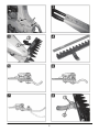
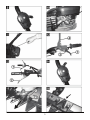
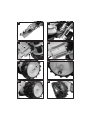
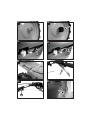
426 036 bcdef 2007 www.al-ko.com 2 3 4 Do not start the engine if anyone is standing in front of the cutter bar – the cutter and wheel drives must not be engaged. Safety instructions General comments Read the operating instructions carefully. Familiarise yourself with the correct operation of the mower. Use the mower on grassy areas only. The cutter drive must be disengaged when the mower is not on a mowable surface. Keep the operating instructions for later use and for subsequent owners. The blade guard must be mounted on the cutter bar if the mower is transported or lifted. Follow the safety instructions and warnings on the mower. Keep hands and feet away from rotating parts. Users Children and juveniles under the age of 16 as well as anyone who has not read the operating instructions must not operate the mower. Local regulations may specify the minimum age. Wear long, close-fitting trousers and sturdy, nonslip footwear. Working area Carefully check the whole area to be mown. Remove all foreign objects, such as stones, sticks, wires, bones, etc. Do not use the mower if there are any persons (caution: children) or animals (including wildlife) in the working area. Never lift or carry the mower if the engine is running. Wait until the cutters have stopped moving, then pull off the spark plug connector. The mower may only be used if the safety clearance determined by the handlebar is maintained. Ensure that you have a secure footing. Always mow across a slope. Never mow up or down a slope or on slopes with an inclination greater than 10°. Keep the exhaust and engine free of leaves, grass and spilt oil. Do not leave the mower unsupervised – pull off the spark plug connector. Operating times Comply with any national regulations regarding operating times for lawn mowers (noise prevention). See the operating manual for operating times. Warning! Petrol is highly flammable! Store petrol in designated containers only. Use the mower only in daylight or if the working area is well illuminated. Refill with petrol outdoors only. Do not smoke while refilling! Operation Always make a visual inspection of the mower before using it. The mower must be in a safe operating condition. Do not open the tank cap or refill with petrol while the engine is running or if the machine is hot. Damaged or worn parts must be replaced immediately. Use the mower only if it is in the technical condition stipulated by the manufacturer. Use a funnel or filling tube to refill petrol to prevent fuel being spilt onto the engine, the housing or on the ground. If petrol has been spilt, do not start the engine. Clean the mower and do not restart the engine until the petrol vapours have dispersed. The person using the mower is responsible for any accidents involving other persons or their property. Do not disable the safety or protective devices on the mower. GB1 For reasons of safety, replace a damaged petrol tank and/or tank cap. Risk of burns! The exhaust as well as the areas around the exhaust may be very hot. Replace damaged mufflers. Spare parts and accessories Use genuine spare parts and accessories only. We reserve the right to make changes to the design and construction without prior notice. Explanation of the symbols on the mower Do not change the governor settings of the engine. Before using the mower for the first time, read the operating manual! Never leave a combustion engine running in an enclosed space – toxic hazard! Keep other people out of the danger area! Safety instructions for the cutter bar Before working on the mower pull off the spark plug connector! Some of the blades on the cutter bar are bare. These can lead to serious injuries if they are not handled with care. Always mount the blade guard on the cutter bar for the following: • mounting the cutter bar onto the mower • cleaning the mower • during transport and storage of the mower • during work on the cutter bar Replace damaged blade guards. Maintenance and storage Before performing any work on the mower: switch off the engine, wait until the cutters have stopped moving and then pull off the spark plug connector. Always wear safety gloves during work on the cutters. Keep hands and feet away from the blades! Intended use This mower is intended for use in private and hobby gardens only. It must be operated with genuine accessories only (cutter bar, winter kit). Non-permitted users: Persons who are not familiar with the operating manual, as well as children, adolescents under the age of 16 and persons under the influence of alcohol, drugs or medication must not operate the mower. If there is petrol in the tank, never store the mower in buildings where petrol vapours can come into contact with naked flames or sparks – Risk of explosion! The petrol tank must be emptied outdoors only. Allow the engine to cool before storing the mower in an enclosed space. Do not spray the mower with water. The mower must be repaired by an authorised specialist company only. GB2 Operating times: Please comply with any municipal regulations on the operation of lawn mowers ! Monday – Saturday: 7.00 – 12.00 a.m. 3.00 – 7.00 p.m. Setting the cutting height The cutting height is adjusted using the skids (2). Sunday and public holidays: not permitted 3 Standard cutter bar steplessly adjustable cutting height up to approx. 6 cm • Loosen nuts . to the required height. • Move the skids • Retighten the nuts. Assembly Assemble this mower in accordance with the separately enclosed assembly manual. Both skids must be set to the same height ! 4 ESM cutter bar Environmental protection, disposal The packaging material is made of recyclable materials. Dispose of the packaging materials in accordance with regulations. a) Mounting the skid holders as skids The cutter bar cuts close to the ground 5 • Mount the adjustable skid holders as shown Switching on the mower in the illustration. (the curved side points downwards). Do not switch on the mower before it has been completely assembled. i b) Mounting adjustable skids The number printed on the left before the text (e.g. 3 ) refers to the diagrams. steplessly adjustable cutting height up to approx. 6 cm 6 • Mount the adjustable skid holders as shown Petrol engine: Before switching on the machine for the first time, full it up with oil and petrol! in the illustration. (the curved side points upwards). 7 • Mount the skids as shown in the illustration. The operating manual supplied by the engine manufacturer for the petrol engine must be followed. 8 Drive gears: Gear oil has been filled at the works. Setting the handlebar height 1 Set the height of the handlebar according to the user's height. The height is usually adjusted to hip level. • Loosen the screws on the housing console. • Set the height of the handlebars using the longitudinal holes. • Retighten the screws. 2 Depending on the model, the handlebar can additionally be adjusted using the upper or lower height settings on the housing console. Setting the cutting height (2 nuts per skid). • Loosen the nuts to the required • Move the skids height. • Retighten the nuts. Both skids must be set to the same height! Starting the engine The clutch levers for the wheel and cutter drives must not be engaged when starting the engine! 9 Set the throttle lever to the << START>> position. 10 Press the primer button 3x with intervals of approx. 2 seconds. If the temperature is below 10° C, press the primer button 5x. If the engine is warm, do not press the primer button! GB3 11 Quickly pull out the starter cable and then allow it to slowly rewind. As soon as the engine is running, set the throttle lever between the "start" and "stop" positions according to the desired engine speed. To start mowing, move the lever to the <START> position - (full throttle). Switching on the cutter bar 12 Unlock the safety catch Before carrying out any maintenance or cleaning work, pull off the spark plug connector! Do not spray the mower with water. Water that enters the ignition system or the carburettor may lead to malfunctions. Clean the mower with a cloth, hand brush, etc. i . Fully depress the clutch lever Maintenance and servicing and hold it tight. The cutters should begin to move only after the lever has travelled half the distance. Readjust the Bowden cable, if necessary – (see under: Adjusting the Bowden cables). When the mower is tilted sideways and depending on the engine manufacturer the following part(s) must point upwards!!!: TECUMSEH: ⇐ the carburettor/air filter BRIGGS & STRATTON: ⇐ the spark plug See the operating manual from the engine manufacturer! Engaging the wheel drive 12 Squeeze the clutch lever and hold tight. Cutter bar to the handlebar The wheel drive should engage only after the lever has travelled half the distance. Readjust the Bowden cables, if necessary (see under: Adjusting the Bowden cables). 13 Model with forward and reverse gears Clutch lever = forward wheel drive Clutch lever = reverse wheel drive Clean the cutter bar after every use, particularly the guidance and sliding surfaces. This means dismounting the cutter. Afterwards, oil all moving parts. Use only biodegradable lubricants! Dismounting the cutter from the cutter bar a) Standard - cutter bar 15 • Remove screws – spring washer and washer under the screw head! forwards. • Pull out part Do not operate both clutch levers at the same time! Only engage: forward wheel drive or or reverse wheel drive at a time. Disengaging the wheel drive 13 Release clutch lever or . Switching off the cutter bar 12 Release clutch lever – observe mounting When remounting part direction – protruding lug must point forwards! • Loosening the cutter guides 16 • Loosen hexagonal nut and unscrew the grub screw a little. • Pull the cutter out sideways. Remount in the reverse order. 15 . Switching off the engine 14 Move the throttle lever to the << STOP >> position. If the lateral play between part and part (natural wear) is greater than 1mm, both parts must be replaced! Setting the cutting play 16 • Screw in the grub screw by hand until you feel a resistance – then give it another ½ turn. • Secure the grub screws with lock nuts. • After setting, the cutters must still be freely movable by hand. GB4 • Carry out a test mow – if the cutting power is insufficient, screw in the grub screw a little. Engine: Changing the oil / air filter / spark plug See the operating manual supplied by the engine manufacturer. b) ESM cutter bar 15 • Remove screws – spring washer and washer under the screw head! forwards. • Pull out part Adjustment of the Bowden cables 19 a) Cutter bar (without a lock nut) observe When remounting part mounting direction – protruding lug must point forwards! For further information on dismounting the cutter as well as maintenance of the cutter bar ⇒ see: the separate sheet: ESM – Cutter Bar Universal SC 15 20 b) Wheel drive • loosen the lock nut • use the adjusting screw Correct setting: The cutters and the wheel drive should only start to move after the lever has travelled half the distance. If the play between part ( and part ( (natural wear) is greater than 1mm, both parts must be replaced! • Retighten the lock nuts. ****** 17 • Lubricate the cutter drive after every 8 operating hours using a commercial multipurpose grease – 2 grease nipples Resharpening and exchanging the cutter blades Resharpen blunt blades with a suitable abrasive stone keeping the same cutting angle (approx. 35 – 40°). Dismount the cutters for this. Worn or damaged blades must be replaced ⇒ customer service centre. Expert inspection is required for the following: • • • • • to readjust if the mower strikes an object if the engine stops suddenly if the cutter bar is bent if the gears are damaged if the V belt is defective Drive gears 18 Check the oil level in the gearbox regularly • Make sure the mower is horizontal. • Unscrew the oil plug. • Oil level: up to lower edge of filling opening Top up with gear oil, if necessary. • Oil grade: gear oil SAE 80 • Oil capacity for mowers with: forward gear only: approx. 0.25 l forward and reverse gear: approx. 0.50 l GB5 Warranty We will rectify any material or production faults on the mower during the statutory period of limitation for claims based on defects in accordance with our choice of repair or replacement. The period of limitation is determined by the laws of the country in which the mower was purchased. Our warranty is only valid under the following conditions: • The machine has been treated properly. • The operating manual has been followed. • Genuine spare parts have been used. The warranty is void if: • Attempts have been made to repair the machine. • The machine has been modified. • The machine has not been used as intended. • Commercial or municipal use, etc. The following items are excluded from the warranty: • Paint damage due to normal wear. • Natural wear and parts that are identified with a frame XXX XXX (X) on the spare parts card. • Combustion engines – separate warranty conditions of the respective enginemanufacturer apply. In the event of a claim covered by the warranty, please contact your dealer or the nearest authorised customer service centre and present this warranty declaration and the sales receipt. The statutory claims of the purchaser based on defects with respect to the seller shall remain unaffected by this guarantee undertaking. Troubleshooting Before carrying out any maintenance or cleaning work, pull off the spark plug connector! Fault Remedial action Engine does not start If the engine is cold: press the primer Full up with petrol Move the throttle lever to the start position Push the spark plug connector onto the spark plug Check the spark plug. Replace, if necessary Clean the air filter Engine power reduced Resharpen / replace the blades → customer service centre Clean the air filter Inexact cut Resharpen / replace the blades → customer service centre Readjust the cutting play Cutter drive / wheel drive not functioning Readjust Bowden cable V - belt defect → customer service centre Faults that cannot be rectified with the aid of this table must be eliminated by an authorised workshop only (customer service centre). GB6 Ausgediente Geräte nicht über den Hausmüll entsorgen! Verpackung, Gerät und Zubehör sind aus recyclingfähigen Materialien hergestellt und entsprechend zu entsorgen. CZ PĜístroje, které již dosloužily, nelikvidujte v domácím odpadu! Balení, pĜístroj a pĜíslušenství jsou z recyklovatelných materiálĤ a musí se likvidovat pĜedepsaným zpĤsobem. GB Do not dispose of worn-out units through the household garbage! The appliance, its packaging and accessories are all produced from recyclable materials and must be disposed of accordingly. SK Opotrebované prístroje nelikvidujte cez domový odpad! Obal, prístroj a príslušenstvo sú vyrobené z recyklovateĐných materiálov a je potrebné ich zodpovedajúco likvidovaĢ. F Les appareils usagés ne doivent pas être mis au rebut avec les déchets ménagers! Les emballages, l’appareil et ses accessoires sont fabriqués en matériaux recyclables et sont à éliminer selon l’usage dans votre pays. RUS Ɉɬɫɥɭɠɢɜɲɢɟ ɫɪɨɤ ɩɪɢɛɨɪɵ ɧɟ ɜɵɛɪɚɫɵɜɚɬɶ ɫ ɛɵɬɨɜɵɦ ɦɭɫɨɪɨɦ! ɍɩɚɤɨɜɤɚ, ɩɪɢɛɨɪ ɢ ɩɪɢɧɚɞɥɟɠɧɨɫɬɢ ɢɡɝɨɬɨɜɥɟɧɵ ɢɡ ɦɚɬɟɪɢɚɥɨɜ, ɩɪɢɝɨɞɧɵɯ ɞɥɹ ɜɬɨɪɢɱɧɨɝɨ ɢɫɩɨɥɶɡɨɜɚɧɢɹ, ɢ ɩɨɷɬɨɦɭ ɞɨɥɠɧɵ ɭɬɢɥɢɡɢɪɨɜɚɬɶɫɹ ɫɨɨɬɜɟɬɫɬɜɭɸɳɢɦ ɨɛɪɚɡɨɦ. I Non smaltire gli apparecchi usati con i rifiuti domestici! L’imballo, la macchina e gli accessori sono prodotti con un materiale che può essere riciclato e di conseguenza vanno smaltiti in modo appropriato. GR ȂȘȞ ʌİIJȐIJİ IJȚȢ ȝİIJĮȤİȚȡȚıȝȑȞİȢ ıȣıțİȣȑȢ ıIJĮ ȠȚțȚĮțȐ ĮʌȠȡȡȓȝȝĮIJĮ! Ǿ ıȣıțİȣĮıȓĮ, Ș ıȣıțİȣȒ țĮȚ IJĮ İȟĮȡIJȒȝĮIJĮ ȑȤȠȣȞ țĮIJĮıțİȣĮıIJİȓ Įʌȩ ĮȞĮțȣțȜȫıȚȝĮ ȣȜȚțȐ țĮȚ ĮʌȠıȪȡȠȞIJĮȚ ĮȞȐȜȠȖĮ. NL Geef het gebruikte apparaat niet met het huisvuil mee! De verpakking, het apparaat en de accessoires zijn van materiaal gemaakt dat hergebruikt kan worden. Lever uw bijdrage hiervoor. TR Hizmetini doldurmuú aletleri ev çöpüyle yok etmeyiniz! Ambalaj, Alet ve Teçhizatlar yeniden de÷erlendirilebilir malzemelerden yapılmıútır ve buna uygun olarak yok edilmelidir E ¡No elimine las máquinas fuera de uso con los residuos domésticos! Los embalajes, la máquina y los accesorios están fabricados con materiales reciclables y deben desecharse adecuadamente. DK Udtjente maskiner må ikke bortskaffes sammen med normalt husholdningsaffand! Emballagen, maskinen og tilbehøret er fremstilles af genbrugelige materialer og skal bortskaffes tilsvarende. P A eliminação de aparelhos usados não deve ser feita através da recolha de lixo normal! A embalagem, o aparelho e seus acessórios são fabricados com materiais recicláveis, devendo ser adequadamente eliminados como lixo reciclável. S Släng inte uttjänta maskiner med hushållssoporna! Förpackning, maskin och tillbehör är tillverkade av återvinningsbara materialier och måste omhändertas i enlighet därmed. H A kiselejtezett gépet ne dobja a háztartási szemétbe! A csomagolás, a gép és a tartozékok anyagai újrahasznosíthatók. Hulladékként történĘ kezelésüket ennek megfelelĘen kell végezni. N Ikke kast utgåtte maskinen sammen med husholdningsavfallet! Emballasje, maskinen og tilleggsutstyr er tilvirket ved hjelp av gjenbruksmateriale, og skal avfallsorteres som gjenbruksmateriale. PL Nie usuwaü zuĪytych urządzeĔ z odpadami domowymi ! Opakowanie, urządzenie i wyposaĪenie wykonano z materiaáów nadających siĊ do recyklingu, naleĪy je zutylizowaü w odpowiedni sposób. FIN D Älä hävitä käytöstä poistettuja laitteita talousjätteen mukana! Pakkaus, laite ja lisätarvikkeet on valmistettu kierrätyskelpoisista materiaaleista, ja ne on hävitettävä asianmukaisella tavalla. Land Firma Tel Fax A AL-KO Kober Ges.m.b.H. (+43) 3578/2515227 (+43) 3578/251538 AUS AL-KO International PTY. LTD (+61) 3/9767-3700 (+61) 3/9767-3799 B Eurogarden NV (+32) 16/805427 (+32) 16/805425 CH AL-KO Kober AG (+41) 56/4183150 (+41) 56/4183160 CZ AL-KO Kober Spol.sr.o. (+420) 382/210381 (+420) 382/212782 D AL-KO Geräte GmbH (+49) 8221/203-0 (+49) 8221/203-138 DK AL-KO Ginge A/S (+45) 98 82 10 00 (+45) 98 82 54 54 E ANMI (+34) 93/3002618 (+34) 93/3001769 F AL-KO S.A.S. (+33) 3/85-763540 (+33) 3/85-763588 GB Rochford Garden Machinery Ltd. (+44) 1963/828050 (+44) 1963/828052 H AL-KO KFT (+36) 29/537050 (+36) 29/537051 HR Brun.ko.-prom d.o.o. (+385) 1 3096 567 (+385) 1 3096 567 I AL-KO Kober GmbH / SRL (+39) 039/9 329311 (+39) 039/9329390 L Bobinage Back (+352) 507622 (+352) 504889 LV AL-KO Kober SIA (+371) 7/409330 (+371) 7807018 N AL-KO GINGE A/S (+47) 64 86 25 50 (+47) 64 86 25 54 NL Mechatechniek B.V. (+31) 18/2567824 (+31) 18/2533895 PL AL-KO Kober z.o.o. (+48) 61/8161925 (+48) 61/8161980 RO OMNITECH TRADING SA (+4) 021 326 36 72 (+4) 021 326 36 79 RUS OOO AL-KO Kober (+7) 095/1688716 (+7) 095/1623238 RUS AL-KO St. Petersburg GmbH (+7) 812/4461084 (+7) 812/4461084 S AL-KO Ginge Svenska AB (+46) (0)31 573 580 (+46) (0)31 575 620 SK AL-KO Kober Slovakia Spol.s.r.o. (+421) 2/45994112 (+421) 2/45648117 SLO SERVIS HUDOBIVNIK (+386) 4 2046884 (+386) 4 2049730 TR ZIMAS A.S. (+90) 232 4580586 (+90) 232 4572697 UA TOV AL-KO Kober (+380) 44/4923396 (+380) 44/4923397 Stand 06/2007 AL-KO Geraete GmbH Head Quarter Ichenhauser Str. 14 89359 Koetz Deutschland Telefon: (+49)8221/203-0 Telefax: (+49)8221/203-138 www.al-ko.com 451 313 1 2 3 4 5 6 7 8 9 10 11 12 13 14 15 16 17 18 19 20 21 22 23 24 a 1 25 26 a 27 28 29 30 31 32 41 42 43 44 a b GB Assembly Assembly of the double wheels BM 5001-R (B&S) Fill the mower with engine oil and petrol only after it has been completely assembled! Pull off the spark plug connector before starting the assembly! i i 13. Remove screw hexagonal screw M8 x 45 hexagonal nut M8 self-locking The number printed on the left before the text (e.g. 3 ) refers to the diagrams. .1. .2. Loosen screws and rotate handlebar console upwards – retighten screws. 14. y Mount axle extender y Re-insert screw and retighten nut. 15. Push the wheel onto the axle extender 16. Check the orientation of the wheel – the tyre profiles should form a V viewed in the direction of travel. Assembly of handlebars on console .3. Handlebars 17. Secure wheel with nut Washer Ø 10 x Ø 35 x 5 Hexagonal nut M10 self-locking .4. Mount handlebars on console. Hexagonal screw M8 x 25 - (2x) Hexagonal nut M8 self-locking - (2x) Bowden cable guide - (1x) 18. Press on protective cap .5. The handlebars can be set to the user's height by attaching them to the lower or upper position. Assembly of Bowden cables a) Bowden cable for throttle .6. Mount the Bowden cable guide together with the lower screw - tighten the nuts. y Set the throttle lever on the right-hand handlebar to the << START>> position. 19. Push the governor lever on the carburettor completely to the left (= start position). Assembly of blade holder .7. Blade holder .8. Mounting bush on the housing accommodate the blade holder. Carry out the following steps on both drive wheels. 20. y Insert the angled end of the Bowden cable wire into the governor lever. to y Insert the Bowden cable sheath in the clip y Gently push back the Bowden cable sheath by hand until a resistance can be felt. Clamp the Bowden cable sheath in this position. .9. Lightly grease the mounting bush and insert the blade holder. 10. Fully insert the blade holder and place the V belt around the pulley. Place the V belt around the lower pulley in the housing. Assembly of recoil springs 11. 12. y Place the mower on its side. y Hook in the recoil springs (2x). GB 1 Do not kink the Bowden cable during assembly. GB b) Bowden cables for the wheel drive i c) Bowden cable for cutter bar This mower has a forward drive and a reverse drive. The Bowden cable for the cutter bar is on the left side of the housing viewed in the direction of travel. 1.) Bowden cable for reverse drive 28 Screw back both nuts on the upper Bowden cable adjuster all the way. 21 The Bowden cable for the reverse drive comes out of the housing below the engine on the right (viewed in the direction of travel) and is additionally labelled R.. 29 Thread the Bowden cable through the console. 30 Thread the Bowden cable through guide on the console. 22 Insert the bent hook of the .R. Bowden cable into the lower hole on the inward side of the right-hand handlebar lever. 31 Thread the bent hook through the hole in the holder and push the adjuster up to the holder. There is no insertion slit on the holder! 23 y Unscrew the foremost nut on the adjuster "a". y Insert the adjuster in the holder and retighten the nut. 32 y Insert the bent hook through the red handlebar lever. y Set the lower adjuster on the housing to its middle position. 24 Lay the Bowden cable along the inner side of the handlebar console. i Correct adjustment of the Bowden cable: see under: "Adjustment of Bowden cables" in the operating manual of the mower. i Correct adjustment of the Bowden cable: See under: "Adjustment of Bowden cables" in the operating manual of the mower. 2.) Bowden cable for forward drive 33 Bind the Bowden cables together with a cable tie on the inner side of the console. 25 The Bowden cable for the forward drive is on the right side of the housing viewed in the direction of travel. Protective cover 26. y Insert the bent hook of the Bowden cable into the lower hole on the outward side of the left-hand handlebar lever. 34 Remove the nuts and washers on the blade holder. 35 Mount the protective cover and tighten the nuts. Do not completely tighten the upper nut (width across flats 19 mm). y Insert the Bowden cable sleeve "a" into the holder on the handlebars. 27 Adjust the lower end of Bowden cable on the housing to the correct setting. See under: "Adjustment of Bowden cables" in the operating manual of the mower. 36 Mount the protective cap on the rear of the housing and secure with a hexagonal drilling screw Ø 4.8 x 16 (1x) and washer Ø 5 (1x). GB 2 GB Cutter bar i 42 43 Screw the cutter bar and blade holder together. Hexagonal screw M8 x 25 (4x) The cutter bar is not included in the scope of delivery! The mounting plate must be inserted between the cutter bar and the blade holder! Carry out the following steps to mount the ESM cutter bar. Please observe the safety information and maintenance instructions from the manufacturer of the cutter bar. 44 There must be a gap of approx. 1 mm between the start of the thread of the headless screw "a" and the drive dog "b". Adjust the headless screw correspondingly. Mount the blade guard on the cutter bar and wear safety gloves! 37 Assembly parts (supplied with the scythe mower): 1x 1x 2x 2x 2x 1x 4x y Assembly of the skids on the cutter bar See the Operating Manual. Guide (plastic) Drive dog Allen screw M8 x 14 Washer Ø 8 Spring washer Ø 8 Mounting plate Hexagonal screw M8 x 25 ********** 38 Screw the guide centrally onto the cutter bar. Allen screw M8 x 14 - (2x) Spring washer Ø 8 - (2x) Washer Ø 8 - (2x) Pay attention to its orientation – the protruding lug must point towards the cutting blades. The spring washer must lie underneath the screw head! 39 Place the mounting plate on the cutter bar. 40 Align the cutter bar on the blade holder in the attachment position - align the drive dog on the centre of the blade holder (turn the V-belt pulley for this). i Lightly grease the drive dog before mounting. 41 y Lift the scythe mower by the blade holder so that the drive dog can be inserted into the guide. y Lower the mower again and insert the headless screw into the drive dog. GB 3 i BM 5001 R (B&S) Art.Nr. 112 431 ca.140cm x 95cm x (101cm/112cm) kg ca. 69 kg cm 91cm / 102cm 3,7 kW 3600 -1 4.00 - 6 ca. 2,25 km/h LWA 102 dB(A) avhw 5,4m/s² D- EG-Konformitätserklärung F- Déclaration de conformité CE NL- EC-verklaring van conformiteit H- EU egybehangzósági nyilatkozat CZ- Prohlášení o shodě s EU N- EF-Konformitetserklæring DK- EF-Overensstemmelseserklæring RUS- Заявление о соответствии нормам ЕС GB- EC Declaration of Conformity I- Dichiarazione di conformità CE E- Declaración de conformidad de la CE PL- Oświadczenie zgodności EWG SK- Prehlásenie ES o konformite S- EG-konformitetsförklaring FIN- EU-yhdenmukaisuusilmoitus SLO- Izjava o konformnosti s priporoèili EU Wir / We / Nous / Noi / Wij / Nosotros / Mi / My / Prohlašujeme / Vi / Me / Мы: ALKO Geräte GmbH Ichenhauserstraße 14 D 89 359 Kötz Германия erklären, dass die Maschine / declare that the machine / déclarons que la machine / dichiariamo che la macchina / verklaren dat de machine / declaramos que la máquina / kijelentjük, hogy az alábbi gép / oświadczymy, że maszyna ta w postaci / že stroj / prehlasujeme, že stroj / erkl rer, at maskinen / förklarar, att denna maskin / ilmoitamme, että kone / заявляем, что данный продукт / izjavljamo, da stroji: Balkenmäher Motofalciatrice Homlokfűnyiró Græsslåmaskine Cutter bar mower Balkmaaier Slåmaskin Nittokone Typ / Type / Tipo / del tipo / típus / typu / Tyyppi / Тип / Tip: Faucheuse à barre de coupe Motosegadora Slåttermaskin BM 870 II BM 875 II BM 5001 R chnittbreite / Cuttingwidth / Largeur de coup/Larghezza di taglio / Maaibreedte / Ancho de corte / Klippebredde / Snittbredd / Leikkausleveys / Vágási szélesség / šířka řezu / Szerokość cięcia / Ширина среза / Širina reza: 87 cm 87 cm 91/102 cm mit folgenden EG-Richtlinien übereinstimmt / conforms to the specifications of the following EC directives / st conforme aux spécifications des directives CE suivantes / è conforma alle seguenti direttive CE / overeenstemt met de volgende CE-richtlijnen / Cumple las siguientes directrices de la CE / megfelel a következő EK-direktíváknak / odpowiada następującym watacznym EWG / odpovídá následujícím směrnicím EU / zodpovedá nasledujúcim smerniciam ES / er i samsvar med følgende EF-direktiver / stämmer överens med följande EG-direktiv / stemmer over ens med følgende EF-direktiver / vastaa seuraavia EU-direktiivejä / соответствует следующим требованиям ЕС-директивы / ustrezjo naslednjim priporočilom EU: 98/37/ EG, 89/336/EWG, egebenenfalls angewendete Normen / Where appropriate applied standards / Le cas échéant, standards appliqués/ norme eventualmente applicate/ toegepaste normen, indien van toepassing / normas eventualmente aplicadas / Применены соответствующие нормативы / upoštevani standardi, če je to potrebno: EN 12733, EN ISO 14982 Kötz Ort / Place / Lieu / Località / Plaats / Localidad / Helyiség / Miejscowość / Miesto / Sted / By / Paikka / Место / Kraj: 19.12.2005 Datum / Date / Data / Dátum / Dato / Дата: De Filippo Unterschrift / Signature / Firma Handtekening / Aláírás / Podpis Underskrift / Signatur / Aika Подпись / Podpis: Geschäftsleitung Beauftragter / Representative / Délégué / Responsabile / Gemachtigd / Delegado / Meghatalmazott / Zleceniobiorca / Představitel / Zodpovedný / Representant / Representat / Autoriseret repræsentant / Valtuutettu / Уполномоченный / Pooblaščenec: Land Firma Tel Fax A AL-KO Kober Ges.m.b.H. (+43) 3578/2515227 (+43) 3578/251538 AUS AL-KO International PTY. LTD (+61) 3/9767-3700 (+61) 3/9767-3799 B Eurogarden NV (+32) 16/805427 (+32) 16/805425 CH AL-KO Kober AG (+41) 56/4183150 (+41) 56/4183160 CZ AL-KO Kober Spol.sr.o. (+420) 382/210381 (+420) 382/212782 D AL-KO Geräte GmbH (+49) 8221/203-0 (+49) 8221/203-138 DK AL-KO Ginge A/S (+45) 98/82-1000 (+45) 98/82-5454 E ANMI (+34) 93/3002618 (+34) 93/3001769 F AL-KO S.A.S. (+33) 3/85-763540 (+33) 3/85-763588 GB Rochford Garden Machinery Ltd. (+44) 1963/828050 (+44) 1963/828052 H AL-KO KFT (+36) 29/537050 (+36) 29/537051 I AL-KO Kober GmbH / SRL (+39) 039/9 329311 (+39) 039/9329390 LV AL-KO Kober SIA (+371) 7/409330 (+371) 7807018 N AL-KO GINGE A/S (+47) 64/862550 (+47) 64/862554 NL Mechatechniek B.V. (+31) 18/2567824 (+31) 18/2533895 PL AL-KO Kober z.o.o. (+48) 61/8161925 (+48) 61/8161980 RUS OOO AL-KO Kober (+7) 095/1688716 (+7) 095/1623238 RUS AL-KO St. Petersburg GmbH (+7) 812/4461084 (+7) 812/4461084 S AL-KO Ginge Svenska AB (+46) 31/573580 (+46) 31/575620 SK AL-KO Kober Slovakia Spol.s.r.o. (+421) 2/45994112 (+421) 2/45648117 SLO Merkur d.d. (+386) 42588290 (+386) 42588805 UA TOV AL-KO Kober (+380) 44/4923396 (+380) 44/4923397 Stand 11/2005 AL-KO Geraete GmbH Head Quarter Ichenhauser Str. 14 89359 Koetz Telefon: (+49)8221/203-0 Telefax: (+49)8221/203-138 www.al-ko.com 451 313