1
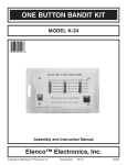
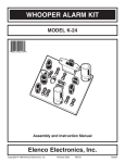
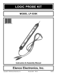
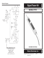
Schematic Diagram
Signal Tracer Kit
MODEL ST-751
Elenco Electronics, Inc.
150 W. Carpenter Avenue
Wheeling, IL 60090
(847) 541-3800
http://www.elenco.com
e-mail: [email protected]
Assembly Instructions
Elenco Electronics, Inc.
Copyright © 1996 Elenco Electronics, Inc.
Revised 2002
REV-D
752751
Parts List
Specifications
If you are a student, and any parts are missing or damaged, please see instructor or
bookstore. If you purchased this signal tracer kit from a distributor, catalog, etc., please
contact Elenco Electronics (address/phone/e-mail is at the back of this manual) for
additional assistance, if needed.
Injector:
Impedance 100W
Signal Level 75mV
Harmonic Spacing 1kHz
Pick Up:
Input Impedance 100,000W
Gain Adjustable 1 to 50
Resistors
Qty.
1
1
1
1
1
1
1
3
1
2
1
1
1
Symbol
Description
R6
R16
R10
R13
R14
R8
R5
R3, R9, R15
R12
R1, R2
R4
R7
R11
100W 5% 1/4W (brown-black-brown-gold)
220W 5% 1/4W (red-red-brown-gold)
1kW 5% 1/4W (brown-black-red-gold)
2.7kW 5% 1/4W (red-violet-red-gold)
3.9kW 5% 1/4W (orange-white-red-gold)
4.7kW 5% 1/4W (yellow-violet-red-gold)
6.8kW 5% 1/4W (blue-gray-red-gold)
10kW 5% 1/4W (brown-black-orange-gold)
47kW 5% 1/4W (yellow-violet-orange-gold)
100kW 5% 1/4W (brown-black-yellow-gold)
180kW 5% 1/4W (brown-gray-yellow-gold)
220kW 5% 1/4W (red-red-yellow-gold)
Trim Pot 220kW
Part #
Symbol
Description
C1
C2, C3, C7
C4,C5,C6,C9
.001mF Discap (102)
.1mF Discap (104)
10mF Electrolytic (Lytic)
Symbol
Description
D1
Q2
Q1
U1
D2
Diode 1N5234
Transistor 3904
Transistor MPS 5172
IC LM-358
LED Diode .125”
131000
132200
141000
142700
143900
144700
146800
151000
154700
161000
161800
162200
191622
Capacitors
Qty.
1
3
4
Part #
231035
251010
271045
DC Input Voltage: 5 to 40 volts
Input Current:
40mA max.
Customer Service
In the event that you encounter difficulty in getting the instrument
to work properly, write or e-mail ([email protected]) us and
explain: (1) the tests that you have made and (2) how the
instrument behaved during these tests. Our experience has
demonstrated that most difficulties can be corrected by an
exchange of letters or a phone call.
Semiconductors
Qty.
1
1
1
1
1
Part #
315234
323904
325172
330358
350001
If the instrument continues to work improperly and you would like
Elenco to locate the problem, send the unit along with a $10.00
check to our Service Department. They will repair, test the unit,
and return it to you with a brief report of the problem.
Miscellaneous
Qty.
1
1
1
1
1
1
1
2
1
1
1
1
1
12”
36”
2”
48”
Description
Part #
PC Board
Switch Slide DPDT
Probe Tip
Knob (white)
Earphone Jack
Case
Earphone 8W
Screw #4 x 5/8”
IC Socket 8-pin
Alligator Clip Black
Alligator Clip Red
Alligator Clip Green
Label
Wire
Cable 3-wire
Tubing #20 PVC
Solder
512751
541023
616001
622017
622102
623007
629350
643450
664008
680001
680002
680003
720510
815820
870801
890020
9ST4
-1-
-10-
Troubleshooting Guide
Introduction
The following guide should help in solving any problems encountered with
your signal tracer. First, check your unit for soldering or wiring errors.
Next, check the voltage at the emitter of transistor Q1. It should measure
between 4.5 to 5.5 volts. If you still have a problem, refer to the following
sections for help.
Assembly of your signal tracer will prove to be an exciting project and give
much satisfaction and personal achievement. If you have experience in
soldering and wiring techniques, you should have no problems. For the
beginner, care must be given to identifying the proper components and
good soldering habits. Above all, take your time and follow the easy stepby-step instructions. Remember, an ounce of prevention is worth a pound
of cure. Avoid making mistakes and no problems will occur.
I. LED does not light:
A) Be sure the red clip is connected to a positive voltage between 5 to
40 volts, and the black clip is connected to ground.
Parts Verification
B) Check the LED, it may be in backwards or open.
Before beginning the assembly process, familiarize yourself with the
components and this instruction book. Verify that all parts are present.
This is best done by checking off each item against the parts list.
C) If 4.5 to 5.5 volts is present at the emitter of transistor Q1, proceed
to II.
D) Check the zener diode D1, transistor Q1, and capacitors C5 and C6
for backwards installation.
E) Make sure R9 and R10 are not interchanged.
II. Weak or no sound in earphones with green clip connected
to probe tip, and the LED is on:
A) Check to see if the IC is in backwards.
B) Must determine if the oscillator or amplifier is at fault. If an
oscilloscope is available, look at the output of the op-amp (pin 1).
There should be 3 to 5V of a 1kHz squarewave.
If no scope is available, put the switch to tip receive position and
remove the green alligator clip from the tip. Touch the tip with your
finger. The earphone will buzz with 60Hz response when the gain
control is fully clockwise and the amplifier is operational.
C) If the oscillator is at fault:
Check the LM-358 op-amp (pins 1, 2, 3, 4, and 8), resistors R1 to
R6 and capacitors C1 and C2 for soldering or wiring errors.
Replace the LM-358 op-amp if there are no solder or wiring errors.
D) If the amplifier is at fault:
Check the LM-358 (pins 4 to 8), trim pot R11, resistors R7, R8, and
capacitors C3 and C4, for soldering or wiring errors.
Replace the LM-358 op-amp if there are no solder or wiring errors.
E) Check switch S1.
-9-
Resistors are identified by their color code as shown in the assembly
instructions.
Soldering
The most important factor in assembling your signal tracer is good
soldering techniques. Using the proper soldering iron is of prime
importance. A small pencil type iron of 25-40 watts is recommended. The
tip of the iron should be the flipplet point type and at all times kept clean
and well tinned. Many areas on the main board are close together and
care must be given not to form solder shorts. Size and care of the tip will
eliminate problems.
For a good soldering job, the areas being soldered must be heated
sufficiently so that the solder flows freely. Apply the solder simultaneously
to the component lead and the component pad on the PC board so that
good solder flow will occur. Be sure that the lead extends through the
solder smoothly, indicating a good solder joint. Use only rosin core solder
of 60/40 alloy. Do not blob the solder over the lead because this could
result in a cold solder joint.
Assemble Components
In all of the following assembly steps, the components must be installed
on the top side of the board unless otherwise indicated. The top legend
shows where each component goes. The leads pass through the
corresponding holes and the board is turned to solder the component
leads on the foil side. Solder immediately, unless the pad is adjacent to
another hole, which will interfere with the placement of the other
component. Clip excessive leads with diagonal cutters. Then, place a
check mark in the box next to the step indicating that the step is complete.
-2-
Step-by-Step Assembly Instructions
Theory of Operation
Refer to Figure 1, install and solder the following resistors.
The diagram on the back cover shows the schematic diagram of the
signal tracer. Its main component is the dual op-amp LM-358. The first
section serves as a squarewave oscillator. Positive feedback is through
resistor R3. The frequency of oscillation is controlled by resistor R4 and
capacitor C1. These components cause the op-amp to oscillate at a
frequency of about 1000Hz. Resistors R1 and R2 are used to bias the
input. Resistors R5 and R6 divide the signal to give an output of 75mV
across the 100W impedance. The squarewave is rich in harmonics which
extend into the AM and FM band of your radio. This allows signal tracing
of AM, RF, and IF stages, and for testing of IF circuits in most FM radios.
R1
R2
R3
R4
R5
R6
R7
R8
R9
R10
R12
R13
R14
R15
R16
R11
100kW 5% 1/4W
100kW 5% 1/4W
10kW 5% 1/4W
180kW 5% 1/4W
6.8kW 5% 1/4W
100W 5% 1/4W
220kW 5% 1/4W
4.7kW 5% 1/4W
10kW 5% 1/4W
1kW 5% 1/4W
47kW 5% 1/4W
2.7kW 5% 1/4W
3.9kW 5% 1/4W
10kW 5% 1/4W
220W 5% 1/4W
Trim Pot 220kW
brown-black-yellow-gold
brown-black-yellow-gold
brown-black-orange-gold
brown-gray-yellow-gold
blue-gray-red-gold
brown-black-brown-gold
red-red-yellow-gold
yellow-violet-red-gold
brown-black-orange-gold
brown-black-red-gold
yellow-violet-orange-gold
red-violet-red-gold
orange-white-red-gold
brown-black-orange-gold
red-red-brown-gold
The second section of the op-amp is designed to be a variable amplifier.
The input impedance of this amplifier is 100,000W. The gain of the
amplifier is adjustable between 1 to 50 times, depending on the setting of
trim pot R11. Resistors R7 and R8 bias the input circuit with C4 serving
as a bypass capacitor, and C3, the input capacitor. The output of the
amplifier is connected through capacitor C9, transistor Q2, and resistor
R16 to the earphone jack.
Trim Pot
Transistor Q1 and the associated components are the voltage control
circuit. Diode D1 is a 5.6V zener, allowing transistor Q1 to produce a
constant 5V output. The circuit is capable of handling input voltages of
between 5 to 40V.
Switch S1 allows the choice of the probe tip to serve as the output of the
oscillator signal, or as the pick up for the test signal.
Figure 1 - Top Legend
Install and solder D1, the 1N5234 diode. Note: the diode has polarity
as indicated by the band. Mount the diode with the band corresponding
to the PC board marking as shown in Figure 2.
Band
Notch
Figure 2
Figure 3
Install and solder the 8-pin IC socket (U1). Carefully install the LM-385
IC (see Figure 3). Be sure that the notch is in the correct direction as
shown in Figure 1.
-3-
-8-
Testing the Signal Tracer
Checking out your signal tracer is fairly easy. You will need a DC voltage
source of between 5 to 40V. A 9V battery will do fine. Connect the red
alligator clip lead to the positive voltage and the black lead to the negative
voltage. The red LED should light up. Next, clip the green lead to the
probe tip and connect the earphone to the jack. You should hear a tone
in the earphone. Vary the gain control and the tone should vary in
amplitude.
Obtain an audio amplifier or an AM radio. Make sure the amplifier or radio
is isolated from the power line. Set the probe slide switch into the tip inject
position. Connect the green lead to the output of the amplifier or radio
speaker. Touch the probe tip to the input of the last stage of the amplifier.
The tone should be heard in the earphone or speaker of the radio.
Continue injection by moving the tip toward the input and output of each
stage. Vary the probe gain to prevent overload of the probe. If you have
an AM radio, try injecting the signal into the IF and RF stages. The signal
tracer produces a 1kHz harmonics which extend into the frequencies of
the AM radio, and you will be able to hear these harmonics as 1kHz
detected signals.
At times, it may be advantageous to reverse the process. Move the switch
to the tip receiver position. Now, connect the green lead to the input of
the amplifier. The probe tip now is used to pickup the signal. Start with
the first stage and continue to the last. This method is helpful if the last
stage of the amplifier is defective.
Should your signal tracer fail to perform as expected, refer to the
troubleshooting guide for help in solving the problem.
Refer to Figure 1 or the top legend on the PC board. Install and solder
the following capacitors.
C1
C2
C3
C4
C5
C6
C7
C9
.001mF (102) Discap
.1mF (104) Discap
.1mF (104) Discap
10mF Lytic (see Figure
10mF Lytic (see Figure
10mF Lytic (see Figure
.1mF (104) Discap
10mF Lytic (see Figure
4)
4)
4)
Figure 4
4)
Install and solder the transistors with the flat side in the direction shown
in Figure 1.
Q1 - 5172
Flat
Q2 - 2N3904
Install D2, the red LED. Cut two 7/16” plastic tubes
to be used as standoffs. Place each LED lead into
the tubing so that the LED stands 7/16” off of the PC
board. Look for the flat side at the base of the LED.
Mount it with the flat side as shown in Figure 1.
Solder into place.
Flat
Tubes
Mount the switch 1/8” off of the PC board, as shown in Figure 5. Install
and solder the switch (S1) in the place shown in Figure 1.
Install the probe tip. Cut a wire to 4 3/4”,
strip 1/4” of insulation off of both ends.
Solder one end to point P on the PC
board. Solder the other end of the wire
to the probe tip groove.
One of two types of jacks is supplied
in your kit. Look at the clip on the
jack for identification and wire
accordingly, as shown in Figure 5.
Cut two wires to 1 3/4” and strip 1/4”
of insulation off of both ends. Solder
the wires to the lugs of the jack
supplied as shown in Figure 5.
Solder the other ends of the wires to
the holes in the PC board marked
“EAR” as shown in Figure 5.
-7-
Electrolytics have polarity.
Place the negative (–) lead in
the correct hole, as marked
on the PC board and part.
Mount the electrolytics so that
they lay on their side.
-4-
Mount switch 1/8” off
of the PC board.
Clip
1/8”
Clip
Figure 5
Prepare the power cord. On one end, use diagonal cutters to strip off
4” of the gray casing to expose 3 wires (BE CAREFUL NOT TO CUT
INTO THE 3 WIRES). Strip off 2” of gray casing off of the other end.
Strip 1/4” insulation off of all 6 wires.
Label
Case Top
Nut
Jack
Cable Notch
Jack Notch
PC Board
Slide the alligator boots onto the 4” wires on the end of the power cord;
red boot on the red wire, green boot on the green or white wire, and the
black boot on the black wire. Then, solder the 3 clips to the wires. Slide
the boots onto the clips.
Bend tabs over the wire.
Clip
Screw
Probe
Notch
Boot
Screw
Figure 6
On the other end of the cable, solder the black wire to the hole on the
PC board marked “GND”. Solder the green or white wire to the hole
marked “C”. Solder the red wire to the hole marked “B+”.
Install the label onto the case. Be careful to place the label on neatly
and correctly. Peel the backing off the expose the glue.
Place the PC board assembly into the case as shown in Figure 6. Use
two #4 screws to hold the case together. DO NOT OVER-TIGHTEN or
the holes may strip out. Tighten the nut down on the earphone jack.
Press the knob onto the gain control shaft.
This completes the assembly. Your unit is now ready for testing.
-5-
-6-