1
Instruction Manual
COMMERCIAL GAS WATER HEATERS
MODELS BTH-120/150/199/250
SERIES 100 & 101
!"#$%&
INSTALLATION - OPERATION - SERVICE
- MAINTENANCE - LIMITED WARRANTY
ANSI / NSF 5
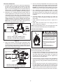
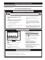
WARNING: If the information in these
instructions is not followed exactly, a fire
or explosion may result causing property
damage, personal injury or death.
Do not store or use gasoline or other
flammable vapors and liquids in the
vicinity of this or any other appliance.
WHAT TO DO IF YOU SMELL GAS:
Do not try to light any appliance.
Do not
touch any electrical switch; do
not use any phone in your building.
Immediately
call your gas supplier
from a neighbor’s phone. Follow the
gas supplier’s instructions.
If you cannot
reach your gas supplier,
call the fire department.
Installation and service must be
performed by a qualified installer,
service agency or the gas supplier.
Read and understand this instruction
manual and the safety messages
herein before installing, operating or
servicing this water heater.
Failure to follow these instructions and
safety messages could result in death
or serious injury.
This manual must remain with the
water heater.
PLACE THESE INSTRUCTIONS ADJACENT TO HEATER AND NOTIFY OWNER TO KEEP FOR FUTURE REFERENCE.
PRINTED 1011
197727-002
TABLE OF CONTENTS
)V(C#)//C=#"J)(#+)(?5C!( $
Supply Gas Line Installation $'
W(#(?/)V(@C#V=?BC=# 4
( 41
4
)
!41
C#?=+J!C=# 6
(*+!
41
`
6
/! 42
!=BBk3^!!; 6
356+ 42
VC 6
TEMPERATURE REGULATION 8$
V(J?()#+!=B=#(#) 7
:;
/;!<(!=> 8$
^= 7
;! 8$
5 8
!=#?=/)@)(B=(?C=# 44
)5 10
!);#6 44
C#)//C=#!=#)C+(?C=#)11
+)44
Rough In Dimensions11
)
C45
?6! 12
J)3!);B
47
/: 12
Temperatures Menu47
!!;
B&$
Heater Status Menu48
)6!&$
Display Settings49
Insulation Blankets &$
Heater Information49
INSTALLATION REQUIREMENTS 14
!
V
50
Gas Pressure Requirements 14
V
:50
Supply Gas Line 14
V
=
50
Supply Gas Regulator 14
?V+
50
)6!C;51
)
14
START UP 52
Mixing Valves 15
Initial Start Up 52
+B 15
)
W
X
;54
!); 15
BW
X
;54
Thermal Expansion 15
!V? 55
Temperature-Pressure Relief Valve 16
:
C 55
!+ 17
LIGHTING THE WATER HEATER 56
Air Requirements 18
Lighting & Operation Labels 56
!;;B
21
TROUBLESHOOTING 58
VENTING INSTALLATION 22
C! 58
General Venting Information 22
!C522
)]
== 58
5!
22
)]
==V! 59
+5!
22
Operational Problems 60
W5C
22
?
)"?
=60
Venting Requirements 24
Momentary Ignition60
Maximum Equivalent Lengths24
Not Enough Or No Hot Water60
Minimum Equivalent Lengths24
VJ/#+/(?!=#+CC=#) 61
B};
;#
;=(24
V
!61
5C)]
25
!61
5C 25
?!);/=
61
+5C 25
+!61
5;C 27
V
B62
);C 29
BC#(##!( 64
B)
64
!;C $
B
!;!$~
DIAGRAMS 67
B
!;;$$
!!^_!!^/
67
Venting Arrangements $8
BTH 120 & 150 Wiring Diagram 68
;!)5 $
BTH 199 & 250 Wiring Diagram 69
;!)+5 $%
!
;+; 70
WATER HEATER INSTALLATION $
Water Piping Diagrams 71
!+C $
/CBC(+??#@ 78
2
SAFE INSTALLATION, USE AND SERVICE
"
6};;
B_;
66;
X
?;
;
C6;
;;
"
"6
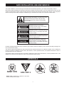
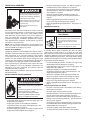
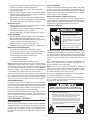
This is the safety alert symbol. It is used to alert you to
potential personal injury hazards. Obey all safety
messages that follow this symbol to avoid possible
injury or death.
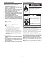
DANGER
DANGER indicates an imminently
hazardous situation which, if not avoided,
will result in injury or death.
WARNING
WARNING indicates a potentially hazardous
situation which, if not avoided, could result
in injury or death.
CAUTION
CAUTION indicates a potentially hazardous
situation which, if not avoided, could result in
minor or moderate injury.
CAUTION used without the safety alert
symbol indicates a potentially hazardous
situation which, if not avoided, could result in
property damage.
CAUTION
;
"
;"
6X
!)+}(;]
W6!
) ! " " 6 ;" ]
}
;)!
""
6;
6}
;
APPROVALS
ASME CRN
ANSI / NSF 5
NOTE: )B( 6;
$
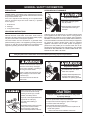
GENERAL SAFETY INFORMATION
PRECAUTIONS
HYDROGEN GAS FLAMMABLE
+= #= J)( :C)/C#!( CV#@ ? :) ^((#
J#+(?(?C;;]
6
;;
}
C
}"
6 6 ; ]
6
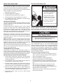
Explosion Hazard
Flammable hydrogen gases
may be present.
& (}
Keep all ignition sources away
from faucet when turning on
hot water.
~ +;
$ V
GROUNDING INSTRUCTIONS
;
# ( ! * ;
V
;
;
: ; 6
;<;>:};
;;
X
"
;;
6
6 ;
; C THERE
):=J/+ ^( #= )B=
C#W =? =(# V/B( #(? :(
VJ!(:(CB(CC)=(#
;
;"
;;]
;
;
]
;
;
Verify the power to the water heater is turned off before performing any service procedures.
Read and understand this instruction
manual and the safety messages
herein before installing, operating or
servicing this water heater.
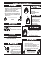
Explosion Hazard
Overheated water can cause
water tank explosion.
Failure to follow these instructions and
safety messages could result in death
or serious injury.
Properly sized temperature and
pressure relief valve must be
installed in the opening provided.
This manual must remain with the
water heater.
Water temperature over 125°F (52°C)
can cause severe burns instantly
resulting in severe injury or death.
CAUTION
Improper installation, use and service may result
in property damage.
Children, the elderly and the
physically or mentally disabled are at
highest risk for scald injury.
Feel water before bathing or
showering.
Temperature limiting devices such as
mixing valves must be installed
when required by codes and to
ensure safe temperatures at fixtures.
4
Do not operate water heater if flood damaged.
Inspect and anode rods regularly, replace if damaged.
Install in location with drainage.
Fill tank with water before operation.
Properly sized thermal expansion tanks are required on all
closed water systems.
Refer to this manual for installation and service.
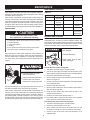
GENERAL SAFETY INFORMATION
Fire or Explosion Hazard
Fire Hazard
Do not store or use gasoline or other flammable vapors and
liquids in the vicinity of this or any other appliance.
For continued protection against
risk of fire:
Avoid all ignition sources if you smell gas.
Do not expose water heater controls to excessive gas
pressure.
Do not install water heater on
carpeted floor.
Do not operate water heater if
flood damaged.
Use only the gas shown on the water heater rating label.
Maintain required clearances to combustibles.
Keep ignition sources away from faucets after extended
periods of non-use.
Fire and Explosion Hazard
Read instruction manual before
installing, using or servicing
water heater.
Use joint compound or Teflon tape
compatible with propane gas.
Leak test before placing the
water heater in operation.
Disconnect gas piping and main
gas shutoff valve before leak
testing.
Install sediment trap in
accordance with NFPA 54.
Breathing Hazard - Carbon Monoxide Gas
Do not obstruct water heater air intake
with insulating blanket.
Gas and carbon monoxide detectors
are available.
Fire and Explosion Hazard
Install water heater in accordance with
the instruction manual.
Do not use water heater with any gas
other than the gas shown on the rating
label.
Excessive gas pressure to gas valve can
cause serious injury or death.
Turn off gas lines during installation.
Contact a qualified installer or service
agency for installation and service.
Breathing carbon monoxide can cause brain damage or
death. Always read and understand instruction manual.
CAUTION
Property Damage Hazard
All water heaters eventually leak.
Do not install without adequate drainage.
Jumping out control circuits or components can
result in property damage, personal injury or death.
Electrical Shock Hazard
Turn off power to the water heater
before performing any service.
Label all wires prior to disconnecting
when performing service. Wiring errors
can cause improper and dangerous
operation.
Verify proper operation after servicing.
Service should only be performed by a qualified service
agent using proper test equipment.
Altering the water heater controls and/or wiring in any way
could result in permanent damage to the controls or water
heater and is not covered under the limited warranty.
Altering the water heater controls and/or wiring in any way
could result in altering the ignition sequence allowing gas to
flow to the main burner before the hot surface igniter is at
ignition temperature causing delayed ignition which can
cause a fire or explosion.
Any bypass or alteration of the water
heater controls and/or wiring will result
in voiding the appliance warranty.
Failure to follow these instructions can
result in personal injury or death.
5
INTRODUCTION
@
;"
6
6
+;
;
; 6 6 C 6" " ABBREVIATIONS USED
6
C
B
6 ;; ;
#)C_;#)C
)B(_;)B(
WB_WB
#(!_#(!
#V_#V
J/_J/
!)_!)
;
V
!;%;
J
6
;
) C ! ^ ; ; ; X
;6
6:6"
6
;
`
)6
QUALIFICATIONS
QUALIFIED INSTALLER OR SERVICE AGENCY
C 6 ]
]
6 `
< #)C
>66C
;"
"6"
]
;6
NOTE: ! 6
;
~ ^ ;#6
;
ANSI Z223.1 2006 Sec. 3.3.83: `
_
6
";";
6<>
" ; <> """6
]
;}
;
]
;
]
;
6X
$ ;
;
;
6X
6 X
]
;
"
C " ;
;
#V
W
!"#)C~~$&*#V8#(
!" #V % !#*!)_^&8'&" #
W
C ! !) !~~&" ! ( ! ; 6
; ! ) " & (
5 ?" !6" =: 88&$& #V
; 6 ; # V
" & ^; " `
"
B~~'
C
]
<#)C6>
]
6 X
; 6 ; ; ;
C 6;
;;
;
ICOMM™ & BACNET COMPATIBLE
; !=BBk ;
; ; !=BBk ; ; 6 C ; " ;
8 C ;
6 ]
" ;6;
C}
]
"
6 B" ) ) ;
6 ;
!=BBk ; ; 6 ; * } ; ;
!
!=BBk;;^!;
6 ;; ; V
;;'~_$%~
!
; (};
;]
;
/ : &~ ?
C+;&&
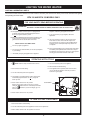
PREPARING FOR THE INSTALLATION
& ?;
;
W)
C; 8 C ";C
;"X
*
V ! ;
6 ;6 ]
) C
;;!
= )" &&~ ` )" )
&"
);"!'&&
;
"
" ; C ;
;
% B
! ]
B
~8_!B?~
)
;!~8_!B?)!;;
B
~&
6
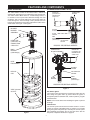
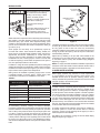
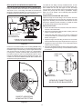
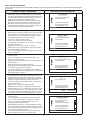
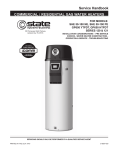
FEATURES AND COMPONENTS
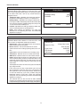
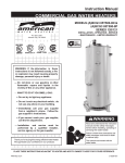
BLOWER/BURNER ASSEMBLY DETAIL
BASIC OPERATION
INTAKE AIR
(combustion air)
CONNECTION
3 INCH PVC
6 ;
6 }
;
B ^
" ;
}
} }
}
*6;
)V
&V
~
BLOWER
BURNER
ASSEMBLY
COMBUSTION
BLOWER
BLOWER
FLANGE
FLAME
SENSOR
MAIN
BURNER
(radial design)
INTAKE AIR
(combustion air)
CONNECTION
3 INCH PVC
HOT SURFACE
IGNITER
120,000 & 150,000 Btu/hr MODELS
MAIN
BURNER
(radial design)
COMBUSTION
BLOWER ASSEMBLY
INTAKE AIR
(combustion air)
CONNECTION
3 INCH PVC
HEAT
EXCHANGER
BLOWER
FLANGE
HELICAL
COIL
HOT SURFACE
IGNITER
MAIN
BURNER
(radial design)
FLAME
SENSOR
199,000 & 250,000 Btu/hr MODELS
Figure 2
VENT (exhaust)
OUTLET
Hot Surface Igniter
; : )
C &~
5! ; "&V<'~!>"
B^
NOTE:!;
6
Flame Sensor
;;;;
;B^
C;6
<$_>;
;; _ ~8 5 W 56 ) )]
=V'
Figure 1
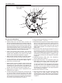
7
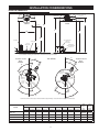
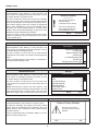
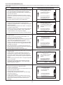
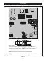
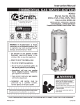
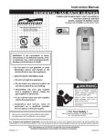
TOP VIEWS
120,000 & 150,000
Btu/hr MODELS
TOP VIEW
6
7
8
9
10
2
5
11
4
12
13
3
2
14
FRONT
15
16
1
17
Figure 3
BTH 120 & 150 COMPONENTS
&&!;
^
& :&~5!*
&~^(}
<6>#;
(}
<6> ; ; ~ 6 ;
]
< > <>^:&~";
66
;
;
6 ;6
<
>;
&$^6#;
!;
^;;
!;
^
;
))]
=
'
$ ! ! ^ <!!^> ; ; !!^
;
"!);=88
&8;
_
? 56 ) ;
_
?56&
8 C_$5!
&~ 5! X
} C; ;))
&8
&J;
"&~;
;;
;
~85W56
% )
) ]
; )
W/&8
J;
(!=<
> X
;
; (!= ; ;
):;
/;!<(!=>8$
/W
#;
6 ;;
; ]
; ;;
)8
W
?]
;&8
&
&&*~#
&%JCB <
;
> JCB " ; /!+ JX
6
6;)!);=
88
' ^ C #; <;
> ;;
&5<}
>_$5!
8
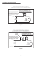
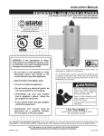
TOP VIEWS (CONT)
199,000 & 250,000
Btu/hr MODELS
TOP VIEW
7
2
8
10
9
6
5
11
4
12
13
3
2
14
FRONT
15
16
1
17
Figure 4
BTH 199 & 250 COMPONENTS
&5<}
>_$5!
& :&~5!*
&&C_$5!
~ 6 ;
]
<>
^:&~";
66
;
; 6 ;6
<
>;
&~^(}
<6>#;
(}
<6> ; ; &$^6#;
!;
^;;
!;
^
;
))]
=
on page 58
$ ! ! ^ <!!^> ; ; !!^
;
"!);=88
8 (^B !;
^; 5V+ <6
]
6>"W565
;
&8;
_
? 56 ) ;
_
?56&
&~ 5! X
} C; ;))
&8
&J;
"&~;
;;
;
~85W56
% ^ C #; <;
> ;;
J;
(!=<
> X
;
; (!= ; ;
):;
/;!<(!=>8$
)
) ]
; )
W/&8
&
&&*~#
&%JCB <
;
> JCB " ; /!+ JX
6
6;)!);=
88
' /W
#;
6 ;;
; ]
; ;;
)8
W
?]
;&8
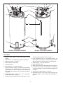
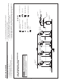
9
4
5
5
6
4
13
3
14
2
3
7
8
2
9
15
10
11
1
12
16
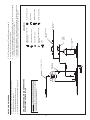
LEFT SIDE
120,000 & 150,000 Btu/hr MODELS
RIGHT SIDE
199,000 & 250,000 Btu/hr MODELS
Figure 5
SIDE VIEWS
& !
" 6 56+?]
;&
$ C_$5!
&/;
"&~;
;;
;
8 ~85W56
&&_&&*~#
!;
^
&~66
_&&*~#
&$)
))
W/&8
% JCB <
;
> JCB " ; /!+ JX
6
6;)!);=
88
&8/W
"
)8W
?]
;
&8
~ !!^
_
;
_
? 56 ) ;
_
?56&
' ;
_
?56_3
10
&5<}
>_$5!
&! &*~ 5! )
V
' &% ! + C $
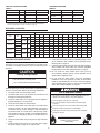
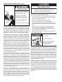
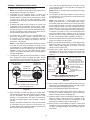
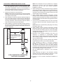
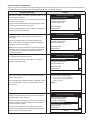
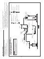
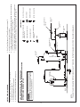
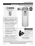
INSTALLATION CONSIDERATIONS
ROUGH IN DIMENSIONS
SUPPLY GAS
CONNECTION
INTAKE AIR CONNECTION
3 INCH PVC
WATER OUTLET
HEIGHT
FRONT
I
BACK
T & P VALVE
E
F
B
H
D
CLEANOUT
VENT CONNECTION
3 INCH PVC
(exhaust elbow)
3/4” NPT DRAIN
1 1/2” NPT
WATER INLET
CONDENSATE
DRAIN CONNECTION
1/2 INCH PVC
C
A
G
These designs comply with the current edition of the American National Standard for Gas Water Heaters, Volume III, ANSI Z21.10.3 / CSA 4.3
as an automatic circulating tank water heater, and automatic storage water heaters.
35°
35°
120,000 & 150,000
Btu/hr
MODELS
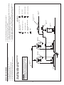
TOP VIEWS
22°
V
3 I ENT
N
PV CH
C
V
3 I ENT
N
PV CH
C
64°
GA
S
68°
199,000 & 250,000
Btu/hr
MODELS
SUPPLY GAS
CONNECTION
VERTICAL
INTAKE AIR
3 INCH PVC
INTAKE AIR
3 INCH PVC
E
LV
E
LV
N
O
UT
VA
A
FRONT
CL
EA
C
LE
P
V
N
O
U
T
&
P
VE
VAL
AIN
DR
&
VE
VAL
A IN
DR
FRONT
A
T
*1 1/2” NPT
WATER
OUTLET
T
*1 1/2” NPT
WATER
OUTLET
18°
18°
45°
45°
45°
45°
* Center line of water outlet on top of the water heaters is approximately 7 inches from the front edge of the water heater.
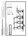
DIMENSIONS
MODEL
SHIP
SHIP
WEIGHT
WEIGHT
A
B
!
D
E
V
G
H
I
STD
ASME
C#!:()*!B
C#!:()*!B
C#!:()*!B
C#!:()*!B
C#!:()*!B
C#!:()*!B
C#!:()*!B
C#!:()*!B
C#!:()*!B
LBS/KG
LBS/KG
BTH 120
$*%~
~%%*%
$*&
$*'
*&8&
8*&~&'
&&*~%'
8~*&%
8%*&~
460/208
490/222
BTH 150
$*%~
~%%*%
$*&
*&8&
%*&'&
*&%8
&&*~%'
$*&
'*&%$
555/252
595/270
BTH 199
$*%~
~%%*%
$*&
*&8&
%*&'&
%*&'&
&&*~%'
$*&
'*&%$
555/252
595/270
BTH 250
$*%~
~%%*%
$*&
*&8&
%*&'&
%*&'&
&&*~%'
$*&
'*&%$
555/252
595/270
Figure 6
11
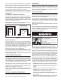
GAS LINE CONNECTION SIZE
STORAGE CAPACITIES
TABLE 1
TABLE 2
† MODEL
SERIES
NATURAL GAS
PROPANE GAS
MODEL
J)W//=#)
LITERS
BTH 120
100/101
$*8#
$*8#
BTH 120
60
227
BTH 150
100/101
$*8#
$*8#
BTH 150
100
$%'
BTH 199
100/101
$*8#
$*8#
BTH 199
100
$%'
BTH 250
100/101
$*8#
$*8#
BTH 250
100
$%'
+]
6"*
;
"
;6
;;
;]
_W/)$'
RECOVERY CAPACITIES
TABLE 3
U. S. GALLONS/HR & LITTERS/HR AT TEMPERATURE RISE INDICATED
V
$V
8V
V
V
%V
V
'V
&V
&&V
&~V
&$V
&8V
!
&%!
~~!
~!
$$!
$'!
88!
!
!
&!
%!
%~!
%!
GPH
461
$8
276
~$
197
&%$
154
&$
126
115
106
99
Propane
LPH
1744
&$
1046
872
747
654
581
~$
476
8$
402
$%8
Natural
GPH
576
8$~
$8
288
247
216
192
&%$
157
144
&$$
&~$
Propane
LPH
2179
&$
&$
1090
'$8
817
726
654
594
545
$
467
Natural
GPH
767
575
460
$8
$~'
288
256
~$
209
192
177
164
Propane
LPH
2904
2178
&%8$
1452
1245
1089
968
871
792
726
670
622
Natural
GPH
960
720
576
480
411
$
$~
288
262
240
221
206
LPH
$$~
2724
2179
1816
1557
&$~
1211
1090
991
908
$
778
Type of
Gas
B
Input
Btu/hr
kW
Natural
BTH 120
&~"
BTH 150
&"
BTH 199
&''"'
BTH 250
~"
$
44
58
%$
Propane
?6';
LOCATING THE WATER HEATER
!
;6;
;;
CAUTION
/]
;
6)
?]
;&
' /6"
" ; ;};
; ]
6
)5?]
;~8
&+ <
!;
^> ; XX
Property Damage Hazard
&&+ ]
6 <}
> ;
X ;<>
;
)5C~~
All water heaters eventually leak.
Do not install without adequate drainage.
}
6
Fire or Explosion Hazard
& ;
~ ;
X;
$ /
X
;;66
8 /6
/
; X
6";;
;"]
"
/;X
% / &~ 5! ))
&8]
;
12
Do not store or use gasoline or other flammable vapors and
liquids in the vicinity of this or any other appliance.
Avoid all ignition sources if you smell gas.
Do not expose water heater controls to excessive gas
pressure.
Use only the gas shown on the water heater rating label.
Maintain required clearances to combustibles.
Keep ignition sources away from faucets after extended
periods of non-use.
Read instruction manual before
installing, using or servicing
water heater.
;""
;; ]
6 ]
; 6 "V;;66
6;
B^
;
}
V;;;"
;
6X
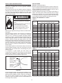
CLEARANCE TO COMBUSTIBLE MATERIALS
6 ;
6 ;
;
;
; 66
NOTE:]
6
;
))6!
ALCOVE
CLEARANCES TO COMBUSTIBLE
AND NON COMBUSTIBLE
CONSTRUCTION MATERIALS
}" ; ;; "
""
]
;)B8;
;;6
CIRCULATION PUMPS
;
;]
X
)+;%&
;
)!
;+;%
;C
# ( !" #V % !
(!"!)!~~&
_
;;
;;
);
;;
]
); ;
;
? ; ;
]
;
TOP COVER
0
0
INSULATION BLANKETS
0
WATER
HARD WATER
HEATER
FRONT
FRONT
TOP VIEW
FRONT VIEW
Breathing Hazard - Carbon Monoxide Gas
Do not obstruct water heater air intake
with insulating blanket.
Figure 7
SERVICE CLEARANCE
6~8<&;>
;
; 6 3 66" ;
;"66"
"66"6
<}
>/6
;
; 6 }
)V
'&%
INTAKE AIR AND VENT PIPE CLEARANCES
;;
;;;
;6
<}
>5
;
;
<X>
EXTENDED VENT TERMINATIONS
6;
$*6
;};
;
]
6<&~;>*6
}
&~]
6<$;>
8)5?]
;~8
; <~> $ ; 8 5! 86"
8;;
!
;
;6;
8
;<>
OPTIONAL CONCENTRIC TERMINATIONS
6;
+5
;
)!;C$
&$
Gas and carbon monoxide detectors
are available.
Install water heater in accordance with
the instruction manual.
Breathing carbon monoxide can cause brain damage or
death. Always read and understand instruction manual.
C
6
}
6;
;}(
]
;";
)
" ) V
!; ;
;;V
]
;
"
"}"
X
DO NOT
"
;
DO NOT6;/!+
DO NOT6;
_
?56
DO NOT6
;
DO
;
;
;6
}
DO
]
;
"
;
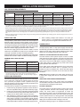
INSTALLATION REQUIREMENTS
GAS PRESSURE REQUIREMENTS
TABLE 4
MODEL
B#CV=/+?())J?(
NATURAL GAS
BC#CBJB)J/@?())J?(
B¡CBJB)J/@?())J?(
PROPANE GAS
NATURAL GAS
PROPANE GAS
NATURAL GAS
PROPANE GAS
BTH 120
8!<&>
&!<~8'>
8'!<&~~>
&&!<~%8>
&!<~~>
&8!<$8'>
BTH 150
8!<&>
&!<~8'>
8'!<&~~>
&&!<~%8>
&!<~~>
&8!<$8'>
BTH 199
!<>
!<>
8'!<&~~>
&&!<~%8>
&!<~~>
&8!<$8'>
BTH 250
!<>
!<>
8'!<&~~>
&&!<~%8>
&!<~~>
&8!<$8'>
B
?
¢$!6
&~"&"^
*;
;
%"%<~"$8%;>&''"~"^
*;
;
&"&<$"%;>):
C6
B;
;
<
>#+<;
>)
;
6
;;
;6
)
;
;;;
C
;&!
;<*
>;
))
W?
]
;))
W/C$')
W?
&8
B};
;
<
>#+<;
>)
;
6
};};
;6
SUPPLY GAS LINE
6;
]
]
6
;
6
;
"
C
DOES NOT
6
; ;
;
;};
;
8
;;
; ;
6
]
6
;
6DO NOT
}
)
6;;]
)W/)$'
MINIMUM SUPPLY GAS LINE SIZE
TABLE 5
† MODEL
NATURAL GAS
PROPANE GAS
BTH 120
$*8#
$*8#
BTH 150
$*8#
$*8#
BTH 199
$*8#
$*8#
BTH 250
$*8#
$*8#
8 ;
; ; ;; 6
6
_
POWER SUPPLY
6 ;
]
&~ 5!"
&<>":"&;
;
"
"#(!"#)C*
#V%!(!"!)!~~&
POWER FLUCTUATIONS AND ELECTRICAL NOISE
; ]
!
X
66
(BC<;>
?VC<]
>;
;;
]
*
/ ; )(/V*_& ) )!_/ ]
6 ;
6}!
;6;
;
;
+]
6"*
;
"
;6
;;
;]
_W/)$'
NOTE:B
6
;
SUPPLY GAS REGULATOR
;};
;
&!<~~>
&8
! <$8' > C 6 _
}
;
C6_
]
& 6_
;
6
^
*
~ 6_
<>
$<&;><~8
;>;
$ 6 _
<>
;
%!
;;
6);X
;
;]
;
14
DEDICATED POWER WIRING AND BREAKERS
+ " 6
POLARITY SENSITIVE
;6;
6 ; ]
; ;; ; ;
C:#
&~
5!
6";
V
"
;
!?6V
;/!+
)(8&
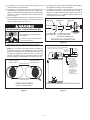
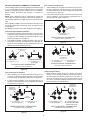
MIXING VALVES
HOT WATER
OUTLET
Water temperature over 125°F (52°C)
can cause severe burns instantly
resulting in severe injury or death.
12” TO 15”
(30-38 cm)
Children, the elderly and the
physically or mentally disabled are at
highest risk for scald injury.
TEMPERED WATER
OUTLET
Feel water before bathing or
showering.
CHECK
VALVE
COLD
WATER
INLET
Temperature limiting devices such as
mixing valves must be installed
when required by codes and to
ensure safe temperatures at fixtures.
CHECK
VALVE
MIXING
VALVE
TO TANK
INLET
;
"
" ; X
) ;
;
};
~V<&&!>
); ; ; X
" " ; *; }; ;__
; C 6 ]
;
"
;
C
;
;B}56
< V
> ;;
B} 66 6 ; !
`
C )6 V ;} 66
;
66
TABLE 6
;
~3$
+^
)
Water Temperature
&V<~!>
Nearly instantaneous
&%V<%%!>
Nearly instantaneous
&V<%&!>
&*~
&V<!>
&_&*~
&8V<!>
/
&$V<8!>
$
&~V<8'!>
More than 5 minutes
Figure 8
#)V
;;
&V<~!>"
6 X
6&V<~!>_
;
X
66 ;#6
;)+;
%&
NOTE:;#)V)]
;
;;
66
CLOSED WATER SYSTEMS
; ;" ]
;
" ; " 6
6 66" 66"6+6
;;
THERMAL EXPANSION
DISHWASHING MACHINES
; ; # )
V
]
;
&~
]
<&$
&%$>V
6~
]
<&%$>"&
]
<&$>"
;
"
66
&V <~!> ;
X
6
;
15
"}<;}>C
;6
;
6
; ;};}
;
<>
6 ; ; }
;;
_
? 56
; 66 }6
6
;
;
_
?56
;}
; } ;
; ;
;
} ! ; 6 6 ;}
)/!8~
+;%&
TEMPERATURE-PRESSURE RELIEF VALVE
CAUTION
Water Damage Hazard
Explosion Hazard
Temperature-Pressure Relief Valve discharge
pipe must terminate at adequate drain.
Temperature-Pressure Relief Valve
must comply with ANSI Z21.22CSA 4.4 and ASME code.
T&P Valve Discharge Pipe Requirements:
Properly sized temperaturepressure relief valve must be
installed in opening provided.
Can result in overheating and
excessive tank pressure.
Can cause serious injury or death.
6 * ; ;
_
? 56 <3
66>;
66
;
]
; ; ; ]
; ? 56 : )
);"
#)C~&~~!)88"]
;)B(
C " 3 66 ;
; ]
;
" ; ;
_
? 56 * 6 66 ;
; ;};
; } ; <&£&"$>
^
*
;
NOTE:C;
_
?56";
;;
6 " 6;
_
? 56 ! ;6;
;
_
?
56;
V";
_
?56;
;6;
;
_
? 56 ;
66C}
<&~;>6]
"
} C ; ;;
;]
^
;6
;
;(}6"6$<'&8;>"
;
66
# 66 ;
_
?56+
<&~ ;>
6 6 X
" " ;"66;
]
]
; ; C
;";
;
16
Shall not be smaller in size than the outlet pipe size of the
66"6
)
)};
);
);
;
_
?56
B
;;};
;}6
}
C;"
;;;
]
)666
66
Burn hazard.
Hot water discharge.
Keep clear of TemperaturePressure Relief Valve
discharge outlet.
The Temperature-Pressure Relief Valve must be manually
!
<&>
;
_
? 56 " <~> ;
X
; ; }; C
;
66" ; ";;
" ;
";
_
?56
*
NOTE: The purpose of a Temperature-Pressure Relief Valve is
6}6;
3 66 ;};};
;;}"
!);;(}&
C
6]
;
_
?56
; 6 ;
CONDENSATE DRAIN
COMBUSTIBLE MATERIAL STORAGE
6 ;
]
};
!;}
; ;
6 6 " V
' C }
<6>
^
(}
;
; " ^ (}
)
; ^ (}
V
; ; /!+" V
!&
NOTE:C^(}
V
;6
;/!+"
EXHAUST (VENT)
ELBOW
CLEANOUT
PLUG IS
REMOVED
TO CLEAR
DRAIN
CONDENSATE DRAIN
LINE CONNECTION
Fire or Explosion Hazard
Do not store or use gasoline or other flammable vapors and
liquids in the vicinity of this or any other appliance.
Avoid all ignition sources if you smell gas.
Do not expose water heater controls to excessive gas
pressure.
Use only the gas shown on the water heater rating label.
Maintain required clearances to combustibles.
Keep ignition sources away from faucets after extended
periods of non-use.
Read instruction manual before
installing, using or servicing
water heater.
;
;"
;;6]
CONDENSATE DRAIN
LINE - FIELD INSTALLED
CONTAMINATED AIR
Breathing Hazard - Carbon Monoxide Gas
FACTORY INSTALLED
CONDENSATE TRAP
Install water heater in accordance with
the Instruction Manual and NFPA 54 or
CAN/CSA-B149.1.
To avoid injury, combustion and ventilation
air must be taken from outdoors.
Do not place chemical vapor emitting
products near water heater.
BUILDING
DRAIN
Figure 9
CONDENSATE DRAIN WATER TRAP
Breathing carbon monoxide can cause brain damage or
death. Always read and understand instruction manual.
!
6;;
;
; 6 )
;
}
Breathing Hazard - Carbon Monoxide Gas
Ensure a functioning water trap is
installed in the condensate drain.
!;
; ; ;
" " ; ;
;
"6;
;
Gas and carbon monoxide detectors
are available.
Install water heater in accordance with
the instruction manual.
Breathing carbon monoxide can cause brain damage or
death. Always read and understand instruction manual.
DO NOT ;6 " V
' 6 6 6
; ) ! +
C$
CONDENSATE PH LEVEL
; 6 ;
6 : 6 8$ C ;;6
]
NOTE:/:6+;
" " )
!+C$
17
+
;C"
;
;;
;
6 6
; <) ; ; ; >
C
""
;" _6 ]
;";6<>
+5
;
6;
;
)5C~~
UNUSUALLY TIGHT CONSTRUCTION
AIR REQUIREMENTS
C
";]
6 ;
" 6
:6"
<
};" " 6 " " 6
">;
6
;
!)
Breathing Hazard - Carbon Monoxide Gas
Install water heater in accordance with
the Instruction Manual and NFPA 54 or
CAN/CSA-B149.1.
To avoid injury, combustion and ventilation
air must be taken from outdoors.
Do not place chemical vapor emitting
products near water heater.
CONFINED SPACE
!)6
;IS LESS THAN
&"^
*<8;>
Breathing carbon monoxide can cause brain damage or
death. Always read and understand instruction manual.
V]
;
;
6;
6
=;
6;
"
6
]
;
6
AND the total Btu/hr input rating of all
DIRECT VENT APPLIANCES
;
; ; )
"
;
;"
;
;"
}
+5
6
;
;
;
^
*
;6
+ ]
;
6
; !
)
EXHAUST FANS
#6
6C
6
]
"
V
6
;
;
}
;"
X
UNCONFINED SPACE
J)6
;IS NOT LESS THAN
&"^
*<8
;>
?;
;;
"
" " B
]
; }
"
6 ;" ; ]
6;
"6
18
}
"6
}
}
; " 6 ;
6 ;; ]
;;}
J ;
6;
;
)"
;
};
C}
LOUVERS AND GRILLES
6"
]
;
" 6
6
" ]
6
6
"
;
66~;
6
6%#;
6
}
FRESH AIR OPENINGS FOR CONFINED SPACES
"
; ; 6 ;
" 6 ;
6 DO NOT refer to these illustrations for the purpose of vent
) 5 C ~~ ;
6
OUTDOOR AIR THROUGH TWO OPENINGS
6;";;&~
<$;;>
"6
) V
&& 6 &<~;;>;<
;;>;
;;
;;
6
;;
6;;
;
& &]
$^
*<%;;~>
"
~ #
;6
OUTDOOR AIR THROUGH TWO HORIZONTAL DUCTS
Figure 10
6 ;
";;&~<$;;>
;;&~<$;;>;
;;
)V
&
(6;;
;&]
8"^
*<;;~>
(
&]
<8;~>
Figure 12
6 ;
";;&~<$;;>
;;&~<$;;>
;
;;
)V
&~
(
6;;
;&]
~"^
*<&&;;~>
OUTDOOR AIR THROUGH ONE OPENING
";
;;
;;
$
Figure 11
19
OUTDOOR AIR THROUGH TWO VERTICAL DUCTS
AIR FROM OTHER INDOOR SPACES
;
6 DO NOT refer to these illustrations for the purpose of vent
) 5 C ~~ ;
6
Figure 14
6 ;
";;&~<$;;>
;;&~<$;;>;
)V
&8
Figure 13
6;6
";;&~<$;;>
;;&~<$;;>;
6
;;
)V
&$
(
6;;
;&]
8"^
*<;;~>
";
;;
;;
$
20
( ;;
;<>
6
;;6
;
;J)
(6;;
;&]
&" ^
* <&& ;;~ > (
&]
<8;~>
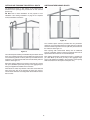
INSTALLATION REQUIREMENTS - COMMONWEALTH OF MASSACHUSETTS
COMMONWEALTH OF MASSACHUSETTS
INSPECTION
V;"66"
6"6
6"
"
!;;}
6;
6 <%> 6 6"
;"
]
;
6 ]
; 6 " " 6 ;}
6~8!B?<~><>&
8
INSTALLATION OF CARBON MONOXIDE DETECTORS
; 6
]
;" ; 6 ;} ;_
6
]
;C"
; 6 ;};
6 " 66
]
;
C
6]
;}
C 6 6 ]
;"
;};_
;
}X6
C 6 ]
; 6 ;;;"
6 <$> ; 6
]
;6
<$>"
;};
APPROVED CARBON MONOXIDE DETECTORS
(;}]
66;#V%~#)C*
J/~$8!)
SIGNAGE
; ;
;
} ;;
; <>6}
6
;6
]
;"_
<&*~>"“GAS VENT DIRECTLY BELOW. KEEP
CLEAR OF ALL OBSTRUCTIONS.”
21
EXEMPTIONS
]
; }; ; ~8 !B? <~><>&
8
& ]
;!&(]
;#
?]
^5;
#V
8^
~ 6 6 ]
;;
;
" " MANUFACTURER REQUIREMENTS - GAS
EQUIPMENT VENTING SYSTEM PROVIDED
;
6 6 ]
; 6 6 ;
6 ; ; ]
;" 6;
]
;6;
& +
6;
6;;
~ ;6;6
;
MANUFACTURER REQUIREMENTS - GAS
EQUIPMENT VENTING SYSTEM NOT PROVIDED
;
6 6 ]
; 6 6
" 6
;" ]
; ;
& 6 ; ]
;
~ 6;
6
^"
;
6
6 ]
;" 6
" 6 " * 6 ; ]
;;
VENTING INSTALLATION
6]
;
+5
~ C "
" ;" ]
;;
;6 <> +
5 ;
6
;
;
Breathing Hazard - Carbon Monoxide Gas
, Install vent system in accordance with codes.
, Do not operate water heater if flood damaged.
, Special consideration must be taken with installations
above 10,000 feet (3,048 m) refer to high altitude
section of this manual.
$ 6;
;
, Do not operate if soot buildup.
, Do not obstruct water heater air intake with insulating
, Do not place chemical vapor emitting products near
8 ;;
;;;
;
6<}
>5
;
;
<X>
, Gas and carbon monoxide detectors are available.
, Never operate the heater unless it is vented to the
;
;
,
6<}
>;
;
6;;
jacket or blanket.
water heater.
outdoors and has adequate air supply to avoid risks
of improper operation, fire, explosion or asphyxiation.
Analyze the entire vent system to make sure that
condensate will not become trapped in a section of
vent pipe and therefore reduce the open cross
sectional area of the vent.
% ;
;
Breathing carbon monoxide can cause brain damage or death.
Always read and understand the instruction manual.
/6<}
>
;;};
;]
6
)5?]
;~8
#6
6
' +6;
;
;
6;
)
;
;"
}
GENERAL VENTING INFORMATION
6 ;
]
6 ! C5 ; 5+5
CATEGORY IV APPLIANCE
! C5 6 6 <}
>
6 ;
6
POWER VENT CONFIGURATION
5 6 ;
; ;
; 6 <}
> 6
66
;6
;)V
8V
8&$8
DIRECT VENT CONFIGURATION
+5
6;
;
;
; 6<}
>+5
6
" 6 + 5 ;
};)V
8~$8
V
8%$
GENERAL VENTING INSTRUCTIONS
;
& DO NOT 5
]
"
?]
;&C
22
&5;
;;
;&*8
<>
&&+6;
"
66;;
&~J66*;
)5?]
;~8
&$J 6 ;)5?]
;~8
&8+ 6 <}
> ;
X ;<>
;
&+6
"
;"
?
" ;
} ;
6 6
" ; ;
6;
&+6;6
6
&%(
;
66;
&)6*
; C ; ";6
";";
;;
}
C;;
&'(
^:&''*~;"~$
~!
5?]
;~8
5C)]
~
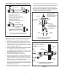
BTH 199 & BTH 250 INTAKE AIR CONNECTION
^: &'' ^: ~ ; ]
]
!;
^
$}$}&*~
&*~
^C
"V
&
FACTORY INSTALLED
INTAKE AIR TEE FITTING
&*~ };&$
6 ; " V
&
&*~ ;
< > " ' " 6 INSPECT/ADJUST INTAKE AIR TEE FITTING
COMBUSTION BLOWER
C &*~ 6;"V
&C
&*~
"X
;X
Adjustment Procedure:
& (
*
1/2 INCH
BRANCH
HOSE BARB FITTING FOR
BLOCKED INTAKE AIR
SWITCH SENSING TUBE
~ +^C
"
V
8'
FERNCO
COUPLING
$ / ; V !;
"V
&%
COMBUSTION BLOWER ASSEMBLY
199,000 & 250,000 Btu/hr MODELS
8 X
&*~
V
&
Figure 15
? ; !;
^
V
"
(
IS NOT
<&_>6
;
'
;&$V
&C
" ; ^ C ;
^C
;
?^C
;
LARGE HOSE
CLAMP
FERNCO
COUPLING
90° TO 130°
3 INCH PVC
INTAKE AIR
TEE FITTING
INTAKE AIR CONNECTION PIPE
199,000 & 250,000 Btu/hr MODELS
Figure 17
END VIEW
CORRECT ORIENTATION
INTAKE AIR TEE FITTING
Figure 16
~$
VENTING REQUIREMENTS
MINIMUM EQUIVALENT LENGTHS
APPROVED MATERIALS
Three Inch Pipe
66;;
J)
6 ;
;;
; $ 6 <}
> %
]
6 <~& ;> ;;
; ]
6 ]
;
5!)
8<)B+~~8&*!)^&&~")B+
&%*!)^&$%$
!5!)
8<)BV_8&&*!)^&$%>
^)<)B+_~&>
66;;
!
J/!)$5!*!5!
Four Inch Pipe
6 ;
;;
; 8 6 <}
> ]
6 <&~ ;> ;;
; ]
6 ]
;
MAXIMUM NUMBER OF ELBOWS
FIELD SUPPLIED FITTINGS
Three Inch Pipe
V
]
6;
V*
]
6
6
* ;
]
6
6;6;};
;
'
$ ; 6;};
;
'C(+5
6
'
'<
>]
6
<&~;>
8<
>]
6~
<%;>
PRIMER AND CEMENT
6;6;};
;}'
8 ; 6;};
;}'C(+5
6
}'
Four Inch Pipe
FACTORY SUPPLIED FITTINGS
<:V> ; 6C!5!^)
";;
X" X 6
; <5! ;> 5! B )B
+_~8W!;!5!B
)BV_8'$
W !; ^) B )B +_~~$
W!;
PIPE SIZE REQUIREMENTS
6;
$86<}
>
C]
66
<&~;>"$;
C
]
6;<&~;>"8
;
NOTE:C]
]
6
C(C
]
66;
]
6;
$
6;
8
MAXIMUM EQUIVALENT LENGTHS
Three Inch Pipe
6 ;
;};
; $ }
6
; ]
6 <&~ ;> ;};
; $ ]
6 <&~ ;> C( = + 5 ]
6<&~;>
Four Inch Pipe
6 ;
;};
; 8 }
6
; &~ ]
6 <$ ;> ;};
;8&~
]
6 <$ ;> C( = + 5 &~]
6<$;>
24
<~> $ ; <5! 8 > V
6 ; ; ;
V ; <}
> ]
66
TABLE 7
Number of
90° Elbows
Installed
=<&>
3 Inch Pipe
4 Inch Pipe
Maximum Feet (Meters)
Maximum Feet (Meters)
8<&$%;>
&&<$;>
<~>
8<&~~;>
&&<$$;>
<$>
$<&%;>
&<$~;>
V
<8>
$<'&;>
&<$;>
V6<>
N/A
'<~';>
)}<>
N/A
'<~%8;>
4 INCH EXTENDED VENT TERMINATIONS
86"
8
;;
!
;<
;6
;
>8;<>
OPTIONAL CONCENTRIC TERMINATIONS
6;
;
+5
8;
! ; ;
!
;
;
6;
Concentric Vent Termination Part Numbers:
8!;¤'$~
VENTING INSTALLATION SEQUENCE
& ? W 5 C
~~ 5?]
;~8
]
; ;
~ +; 5 + 5 6
;;
)
6
6;$8$
$
' 6<}
>;
;;
;&*8
<
>
&C $ 6 6 }
&&C8$}
V
&
$ }
8 }
$
&<8;>
DIRECT VENT INSTALLATION
5C~
+5C~
POWER VENT INSTALLATION
& ? W 5 C
~~ 5?]
;~8
]
; ;
5
~ +; 5 ; 6;)V
8V
8&$8
$ +;6"5
?]
;~8
8 6 ; ; /
6
;;
;
C;
C6;6"
"
5;C~%
C 6 ; " ");C~'
; ; 6
% 6;
6
;
;;
6
6<&~;>6
6$<'&;>
+6;
4” PIPE FIELD
SUPPLIED
& ? W 5 C
~~ 5?]
;~8
]
; ;
+ 5
~ +; + 5 ; } <> + 5 ;
)V
8~3V
8$$8V
88
V
8%$
$ +; 6 5?]
;~8
8 6
; ; /
6 ;;
; C;
C ; 6 ; 6" " 5;C~%
C;
6;"
"
);C~'
C ;<> !
;C$
;<> ; C
6
% 6 ;
6 ;
;;6
6<&~;>6
6$<'&;>
+6;
' ;6
;
} ; ]
;
)V
~&~
4” x 3” REDUCER
FIELD SUPPLIED
3” PIPE FIELD
SUPPLIED
NOTE:)
;}6;
;
;;;"
;
}6
;;;
EXHAUST ELBOW
VENT CONNECTION
FACTORY INSTALLED
VENT (EXHAUST) CONNECTION
&6<}
>;
;;
;&*8<
>
Figure 18
25
&&C $ 6 6 }
&8C$
&~C 8 6 $ }
V
&
~$}
8}$
&<8;>
&C8$
V
~$
8 } $ &
<8;>
&$(
C)C!
;6
)V
&'
4” PIPE FIELD
SUPPLIED
3” PIPE FIELD
SUPPLIED
3” PIPE FACTORY
INSTALLED
INTAKE AIR
Breathing Hazard - Carbon Monoxide Gas
Do not obstruct water heater air intake.
4” x 3” REDUCER
FIELD SUPPLIED
Gas and carbon monoxide detectors
are available.
INTAKE AIR CONNECTION
Install water heater in accordance with
the instruction manual.
Breathing carbon monoxide can cause brain damage or
death. Always read and understand instruction manual.
Figure 20
NOTE: + 6 C ! + 5 = ;6
;;6;
; ;
; ^ C
;
120,000 & 150,000
Btu/hr MODELS
COMBUSTION
BLOWER
3” COUPLING OR TEE
FACTORY INSTALLED
INTAKE AIR CONNECTION
INSTALL TEE FITTING AS CLOSE TO WATER HEATER
INTAKE AIR CONNECTION AS POSSIBLE
FACTORY
INTAKE AIR
CONNECTION
INTAKE
AIR
PIPING
FIELD SUPPLIED
3” x 3” x 1/2” TEE
WITH HOSE BARB
FITTING INSTALLED
199,000 & 250,000
Btu/hr MODELS
CONNECT FIELD
SUPPLIED FLEXIBLE
DRAIN HOSE TO BARB
FITTING AND FORM A
LOOP WATER TRAP IN
DRAIN HOSE
INTAKE AIR SCREEN
RUN DRAIN HOSE
TO SUITABLE FLOOR
DRAIN SEPARATELY
FROM OTHER
CONDENSATE DRAINS
3 INCH INTAKE AIR CONNECTIONS
FACTORY INSTALLED
INTAKE AIR SCREEN
INTAKE AIR CONDENSATE TEE INSTALLATION
(remove for Direct Vent)
Figure 19
Figure 21
26
6;;
6;;
;
~8<&;>;
V
~~C;
8<&~~;>
VERTICAL TERMINATION INSTALLATION
& +;;<>
NOTE:6;
"V
~~
~ C 6 <}
> 5
6 } 6 ]
; V
~$V
~8~;
;
;
NOTE:=6;;
;;
;~8<;>6"6
&<$;>)V
~8~
$ C 6 + 5
6 } 6 ]
; V
~$V
~8~;
;
;
NOTE: = 6
;;
;;
;~8<;>6
" 6 & <$ ;>
)V
~8~
8 C 6 5 6
;
6;;
V
~$V
~8~
;6;;
;;
;
&~<$;>"&<8;>!"6
6}6V
~$
~
C 6 + 5
6 ;
6;
;
V
~~
6;;
;V
~
~
; 6 ;
;
;;
;&~<$;>"&<8;>
!" 6 6 } 6 V
~$V
~~
* 6 ; ;
; ; 6
; }; *
C;
};*
6 ; ;
;;
; ~8 <& ;>
V
~ ~ C ; 8 <&~~
;>
% !
8<&;>;$
<&$;>;8<>
NOTE:^
)
<> ;]
6
;
V
~$~
' ) ]
6 6 ]
6 V
~$" V
~8 V
~~
&C
*6;<>
' V
~$~
'
;;
}6
} ; ~
<;>"V
~$~
&&?
5C~+5
C~;
* 6 ;<> INTAKE AIR TERMINATION
45° ELBOW WITH
DOME SHAPED DEBRIS
SCREEN
VENT TERMINATION
45° ELBOW WITH
RECESSED DEBRIS
SCREEN
STANDARD FACTORY SUPPLIED TERMINATIONS
Figure 22
27
2” (5 cm)
MAXIMUM
24 INCHES (61 cm) MINIMUM
48 INCHES (122 cm) IN COLDER CLIMATES
FACTORY SUPPLIED
STANDARD TERMINATION
POINTED DOWN TOWARDS
THE GROUND
FIELD
SUPPLIED
90° ELBOW
FIELD
SUPPLIED
90° ELBOW
NOTE: INTAKE AIR
TERMINATION
SHOWN HERE
FIELD SUPPLIED
PLUMBING
ROOF BOOT
OR FLASHING
INTAKE AIR
TERMINATION
VENT (EXHAUST)
TERMINATION
FACTORY SUPPLIED
STANDARD TERMINATIONS
POINTED DOWNWARD
MAINTAIN 12” (30 cm)
18” (45 cm) FOR CANADA
MINIMUM CLEARANCE
ABOVE HIGHEST
ANTICIPATED SNOW LEVEL.
MAINTAIN 12” (30 cm)
18” (45 cm) FOR CANADA
MINIMUM CLEARANCE
ABOVE HIGHEST ANTICIPATED
SNOW LEVEL.
FIELD SUPPLIED
PLUMBING
ROOF BOOTS
OR FLASHINGS
VERTICAL TERMINATION - DIRECT VENT
STANDARD TERMINATIONS
FIELD
SUPPLIED
STRAP/SUPPORT
Figure 25
VERTICAL TERMINATION(S) INSTALLATION
INTAKE AIR AND/OR VENT (EXHAUST)
Figure 23
IF LESS THAN
10 FEET (3 m)
24 INCHES (60 cm)
MINIMUM HEIGHT ABOVE
NOTE: VENT
TERMINATION
SHOWN HERE
INTAKE AIR AND/OR VENT
TERMINATION(S) MUST BE A
MINIMUM OF 24 INCES (60 cm)
ABOVE ANY PARAPET, VERTICAL
WALL OR STRUCTURE WITHIN
10 FEET (3 m) HORIZONTALLY.
VERTICAL TERMINATION(S) FLAT ROOF CLEARANCE
INTAKE AIR AND/OR VENT (EXHAUST)
Figure 24
28
% !
8<&;>;$
<&$;>;8<>
SIDEWALL TERMINATION INSTALLATION
& +;;<>
NOTE:6;
"V
~~~%
NOTE:^
~ C 6 <}
> 5
}
]
; ;"
V
8 $" ; ;
;
!
<> $ <' ;>
'<~8&;>
)V
~%
$ C 6 + 5
}
]
;;"
V
8'$%"6;
;
;
;
8 C 6 ; + 5 ;
;;
; ~8 <& ;> " ;
6 " 6
;"V
~
NOTE:C;
8 <&~~ ;> 6;6
;
_ 6 ; }
6;;;
!
C6;+
5 6 ; ;
; 6
;
_V
~
VENT (EXHAUST)
TERMINATION
INTAKE AIR
TERMINATION
NOTE: 5 ; ¥ }
&8VC;6
}
6
6}
6
} 6 ; 6 (}}6
;};
;<&~;>;6
; 6 ;"6;6
"5;C~%
' !;*6;<>
6)
&)
;<>6<>
* 6 ; ;
< > <>
&& ; " ;<>
;6
(
;<> )
V
~%
METAL PLATES
INSTALL INSIDE
AND/OR OUTSIDE
FROM
WATER
HEATER
ELEVATION
INSTALL ON
INCREASE EXPOSED VENT
PIPING UP TO A MAXIMUM
OF 6 INCHES (15.2 cm) FROM
WALL TO HELP PREVENT VAPOR
FROM DISCOLORING THE WALL
SURFACE IN COLDER CLIMATES
FACTORY SUPPLIED
STANDARD TERMINATION
POINTED DOWN
TOWARDS THE GROUND
COUPLING
CENTERLINE
INTERIOR WALL
KEEP INTAKE AND VENT
TERMINATION SCREENS
CLEAR OF DEBRIS
EXTERIOR WALL
SIDEWALL TERMINATION INSTALLATION
INTAKE AIR AND/OR VENT (EXHAUST)
24 INCHES (61 cm) MINIMUM
Figure 27
48 INCHES (122 cm) IN COLDER CLIMATES
&~
<
>
<>
<>
SIDEWALL TERMINATION - DIRECT VENT
STANDARD TERMINATIONS
&$
Figure 26
* 6 ; ;
;;
"
6 ; }; _ *
;
};_*
:6"6
; ;
;;
; ~8 <& ;>
C;
8<&~~;>)V
~
29
&8 ; <> 6<>
&C
<>
^ ; ; ;<> )V
~%
&?
5C~+5
C~;
* 6 ;<> CONCENTRIC TERMINATION INSTALLATION
& ! ; ;
^:
&~_~;;
8;
#
;'$~!
;
;6
;
;
~ +;;
NOTE:?;
;"
;
666
$ ;6
}6]
;
;"V
$$&
;
;
;
8 ;6
";6;
;;
;&
<$;>;"6
V
~
NOTE:C]
&<$;>"
6 ;" ; ;
) 5 ;
C~%
;
} ]
; ;" V
8' $%" ;
;
;
;
; 6
]
;
;
;;)$~$$
;;
% !
<&$;>;8
;;
NOTE:^
;
; 6
; ; ; ;
; ;
;
)B
!;
;$$
' +; ; ;; ]
6;
;
; 6 ;
CONCENTRIC TERMINATION(S)
MUST BE A MINIMUM OF 10 FEET
(3 m) AWAY FROM ANY PARAPET,
VERTICAL WALL OR
STRUCTURE.
) V
~' $& ;};
; ;;
;
8;
} ;
DO NOT ; ; ;
;
;6;
;;
};
J )+?_~ } 8 ;
; ;
< > !
;;
;<6>
4 INCH CONCENTRIC TERMINATION
FLAT ROOF CLEARANCE
& 8 C ! ; C $&
Figure 28
$
86_
;
8}
$ $ <&
>!;
4 INCH CONCENTRIC TERMINATION INSTALLATION
INTAKE AIR CONNECTION
3 INCH PVC
3” x 3” x 4”
Y FITTING
INTAKE AIR PIPE
VENT CONNECTION - 3 INCH PVC
VENT PIPE
' ?
+5C~;
6 ;
VENT
VENT CAP
VENT PIPE IS 2 1/2 INCH SDR-26 PIPE
SUPPLIED LENGTH 37 INCHES (94 cm)
MAXIMUM ALLOWABLE LENGTH 73 INCHES (185 cm)
MINIMUM ALLOWABLE LENGTH 25 INCHES (64 cm)
COMBUSTION
AIR
INTAKE AIR PIPE IS 4 INCH SDR-26 PIPE
SUPPLIED LENGTH 24 INCHES (60 cm)
MAXIMUM ALLOWABLE LENGTH 60 INCHES (152 cm)
MINIMUM ALLOWABLE LENGTH 12 INCHES (30 cm)
MAINTAIN 12” (30 cm)
18” (45 cm) FOR CANADA
MINIMUM CLEARANCE
ABOVE HIGHEST ANTICIPATED
SNOW LEVEL. MAXIMUM OF
24” (60 cm) ABOVE ROOF.
ROOF FLASHING
(field supplied)
INTAKE AIR PIPE
Y FITTING ASSEMBLY
STRAP
(field supplied)
NOTE: SECURING STRAP
MUST BE FIELD INSTALLED
TO PREVENT MOVEMENT
OF TERMINATION KIT
VENT CAP
VENT PIPE ASSEMBLY
VENT
PIPE
4 INCH CONCENTRIC TERMINATION KIT
FOUR PIECE KIT - FIELD ASSEMBLY REQUIRED
Figure 29
INTAKE
AIR PIPE
4 INCH CONCENTRIC TERMINATION
VERTICAL INSTALLATION
;8;?
V
~'"V
$V
$&
Figure 30
& !;@;
~ )@;;
; (
; ;
;
$ )
@;
;]
6
;
8 = ;6@
;
NOTE: SECURING STRAP MUST BE
FIELD INSTALLED TO PREVENT
MOVEMENT OF TERMINATION KIT
IN SIDEWALL.
VENT
PIPE
COMBUSTION
AIR
STRAP
(field supplied)
VENT
)
;
!;66_
;
~
; ; ;
6
;*6*6
% C6*6;@
;"(
;;6;
;@
$ 6 ; ;
$&
1 INCH
MAXIMUM
INTAKE
AIR PIPE
4 INCH CONCENTRIC TERMINATION
SIDEWALL INSTALLATION
Figure 31
MULTIPLE CONCENTRIC TERMINATION CLEARANCES
Four Concentric Terminations
;
;6
]
<> ; ;
(
;
; ]
& ;
};;
V
$8
V
$
NOTE: ;
; 6 6<}
>!
;
;
~ V
;};
;
;;
; ; };V
$8
A
;
; V
$~ ;
;
CONCENTRIC
TERMINATION
CAPS END VIEW
A
)B
!;;$$
Close Proximity & Standard Clearance
& ;
;;
<
>;};
;~<;>";
_V
$~";
};)V
$%$$
A = 0 - 2 INCHES (0 - 5 cm)
CLOSE PROXIMITY
FOUR CONCENTRIC TERMINATIONS
(THROUGH A ROOF OR SIDEWALL)
~ ;
; ;
;;
;~8<&;>";^_
V
$~"};<6>
A
CONCENTRIC
TERMINATION CAPS
END VIEW
A
V
$8
CONCENTRIC
TERMINATION
CAPS END VIEW
CLOSE PROXIMITY
STANDARD CLEARANCE
A = 0 - 2 INCHES (0 - 5 cm)
B = 24 INCHES (61 cm)
OR GREATER
A = 0 - 2 INCHES (0 - 5 cm)
CLOSE PROXIMITY
B = 24 INCHES (61 cm)
OR GREATER
FOUR CONCENTRIC TERMINATIONS
TWO CONCENTRIC TERMINATIONS
(THROUGH A ROOF OR SIDEWALL)
(THROUGH A ROOF OR SIDEWALL)
V
$
Figure 32
Groups Of Terminations
Three Concentric Terminations
& ;
;;
};;V
$$
~ C }; ; ;;
;^V
$$
A
A
B
OR
CONCENTRIC
TERMINATION
CAPS END VIEW
B
& ;
;
};
V
$/
V
$;
; 6 ; ;
6
A
B
B
CONCENTRIC
TERMINATION
CAPS END VIEW
A
A
THIRD
TERMINATION
A = 0 - 2 INCHES (0 - 5 cm)
CLOSE PROXIMITY
A = 0 - 2 INCHES (0 - 5 cm)
CLOSE PROXIMITY
B = 24 INCHES (61 cm)
OR GREATER
B = 24 INCHES (61 cm)
OR GREATER BETWEEN
GROUPS OF FOUR
THREE CONCENTRIC TERMINATIONS
EIGHT CONCENTRIC TERMINATIONS
(THROUGH A ROOF OR SIDEWALL)
(THROUGH A ROOF OR SIDEWALL)
V
$
V
$$
$~
MULTIPLE CONCENTRIC TERMINATION ARRANGEMENTS
Four Concentric Terminations
; ; ;
; V
;;};
V
$)V
$8V
$$~
; ;
)B
!;!$~
; ;
SIDEWALL
NOTE: ;
; ;;;
;;
;
Two Concentric Terminations
;;};
V
$% ;)V
$~$~
; ) V
$$ $~ ;
SIDEWALL
ROOF
Figure 38
Eight Concentric Terminations
ROOF
( ; ; " };" V
$' )
V
$$~;
/
V
$$~;
;6;;
6
SIDEWALL
Figure 37
ROOF
Figure 39
$$
VENTING ARRANGEMENTS
Power Vent Vertical
Figure 40
Power Vent Horizontal
Figure 41
Direct Vent Vertical
Figure 42
Direct Vent Horizontal
Figure 43
$8
VENTING ARRANGEMENTS
Direct Vent Vertical Vent Horizontal Intake
Figure 44
Direct Vent Horizontal Vent Vertical Intake
Figure 45
Direct Vent Vertical Concentric
Figure 46
Direct Vent Horizontal Concentric
Figure 47
$
TERMINATION CLEARANCES SIDEWALL POWER VENT
POWER VENT
(using room air for combustion)
EXTERIOR CLEARANCES FOR SIDEWALL VENT TERMINATION
G
V
D
H
A
v E
L
v
B
FI XE D
CLOSED
V
OPERABLE
F
B
B
C
V
OPERABLE
V
B
FI XE D
CLOSED
M
K
J
A
X
V
X
V
B
V
B
V
X
VENT TERMINAL
AIR SUPPLY INLET
AREA WHERE TERMINAL IS NOT PERMITTED
Figure 48
CANADIAN INSTALLATIONS
A
!6"
6"" &~<$;>
B
!
;
1
<&;>
&"^
*<$>"&~<$
;>&"
^
*<$>&"^
*<$
>"$<'&;>
6&"^
*<$>
US INSTALLATIONS
2
&~<$;>
8<&~;>
&<$;>6
opening
CANADIAN INSTALLATIONS
H
I
1
US INSTALLATIONS
!
}
above meter/regulator
assembly
$<'&;>
$<'&;>&
&<8;>
<8;>6;*
above the meter/regulator
regulator assembly
assembly*
!6
regulator vent outlet
$<'&;>
<&;>
&"^
*<$>"&~
<$;>
&"^
*<$>&"
^
*<$>"$<'&;>
6&"^
*
<$>
<&$;>
C
!
;
&~<$;>
&~<$;>
J
!
;
;
D
5
6
above the terminal
&~<$;>
~<&
;>;
of the terminal
&~<$;>
K
!
;
inlet
E
!
6
&~<$;>
&~<$;>
L
!66
6
%<~&$;>
6
F
!
~<;>
~<;>
M
!
6""" &~<$;> G
!
&<8;>
&<8;>
$<'&;>
8<&~;>
&
<$;>6
$<'&;>6
&<$;>
%<~&$;>
&~<$;> &C
!)^&8'&"#
WC!
~C
#)C~~$&*#V8"#V
W!
6;666;6
;6"""
;;
;
!]
;
;
$
2
TERMINATION CLEARANCES SIDEWALL DIRECT VENT
DIRECT VENT
(using outdoor air for combustion)
EXTERIOR CLEARANCES FOR SIDEWALL VENT TERMINATION
G
V
D
H
A
v E
L
v
B
FI XE D
CLOSED
V
OPERABLE
F
B
B
C
V
OPERABLE
V
B
FI XE D
CLOSED
M
K
J
A
X
V
X
V
B
V
B
V
VENT TERMINAL
X
AIR SUPPLY INLET
AREA WHERE TERMINAL IS NOT PERMITTED
Figure 49
CANADIAN INSTALLATIONS
1
A
!6"
6""
B
<&;>
&"^
*<$>"&~
<$;>
!
&"^
*<$>
;
&"^
*<$>"$
<'&;>
6&"^
*<$>
&~<$;>
US INSTALLATIONS
2
CANADIAN INSTALLATIONS
1
US INSTALLATIONS
!
$<'&;>&
}
<8;>6;*
above meter/regulator
regulator assembly
assembly
$<'&;>
&<8;>6
meter/regulator assembly*
I
!6
regulator vent outlet
$<'&;>
$<'&;>
<&;>
J
!
;
;
<&;>
&"^
*<$>"&~
<$;>
&"^
*<$>&"
^
*<$>"$<'&;>
6&"^
*
<$>
<&;>
&"
^
*<$>"'<~$
;>
&"^
*<$>
"^
*<&>"&~
<$;>
6"^
*<&>
<&$;>
$<'&;>6
&<$;>
&~<$;>
<&;>
&"^
*<$>"
'<~$;>
&"^
*<$>
"^
*<&
>"&~<$;>
6
"^
*<&>
H
C
!
;
D
5
6
6;
&~<$;>
~<&;>;
;
&~<$;>
K
!
;
inlet
E
!
6
&~<$;>
&~<$;>
L
!6
6
%<~&$;>
66
%<~&$;>
F
!
~<;>
~<;>
M
!
6"""
&~<$;>
G
!
&<8;>
&<8;>
<&;>
2
&~<$;> &C
!)^&8'&"#
WC!
~C
#)C~~$&*#V8"#V
W!
6;666;6
;6"""
;;
;
!]
;
;
$%
WATER HEATER INSTALLATION
&*~5!
CONDENSATE DRAIN INSTALLATION
C ;
; $ DO NOT;6";
V
;]
& (
*
65!;5!;
&*~5!_;;
;]
&*~5!<
>
!
+;
V;
INSTALLATION NOTES
~ C &*~ 5! !+
"V
V
&
INSTALLATION INSTRUCTIONS
$ ;6
(
}
;<&~;>6
"}
"V
NOTE: C ; ;; ;
& ; 6
6:68$C
;;6
]
/:6+;
" " 8 (
66
"V
&
^;
6
(
" )J~
~ ;
CONDENSATE DRAIN
LINE - FIELD INSTALLED
EXHAUST (VENT)
ELBOW
CLEANOUT PLUG SHOULD
FACE TOWARDS THE FRONT
OF THE WATER HEATER FOR
SERVICE ACCESS
FACTORY INSTALLED
CONDENSATE TRAP
DRAIN LINE TO
TERMINATE NO
MORE THAN 6
INCHES (15.2 cm)
ABOVE DRAIN
BUILDING
DRAIN
Figure 50
PVC PIPE NIPPLE
½” NPT
PVC BUSHING
1 ½” SLIP x ½” SLIP
PVC TEE FITTING
1 ½” SLIP x 1 ½” SLIP x ½” NPT
½” PVC 90° ELBOW
CONDENSATE DRAIN
CONNECTION. FIELD
INSTALLED DRAIN
LINE CONNECTS HERE
PVC BUSHING
1 ½” SLIP x 1 ¼” NPT
½” PVC PIPE NIPPLE
PVC PIPE PLUG
1 ¼” NPT
½” PVC 90°
STREET ELBOW
CLEANOUT PIPE
PLUG SHOULD
BE ORIENTED TO
THE FRONT OF THE
WATER HEATER FOR
SERVICE ACCESS
CONDENSATE TRAP DETAIL
Figure 51
$
SUPPLY GAS LINE INSTALLATION
GAS LINE SIZING
!
;
]
6 6 6 DO NOT
}
^
;
]
;
]
; ; C ;
";6
;
B;
;]
&8+6]
6*
;;;;"
;6
) *; <>
'6
6'
!<&~>
"
;
;#
SUPPLY GAS LINE SIZING U. S. UNITS
Fire and Explosion Hazard
TABLE 8
Do not use water heater with any gas
other than the gas shown on the rating
label.
Excessive gas pressure to gas valve can
cause serious injury or death.
Turn off gas lines during installation.
Contact a qualified installer or service
agency for installation and service.
LENGTH
#=?B/C?=#C()C()<C#!:()>
IN
INPUT IN THOUSANDS BTU/HR
V((
&*~
$*8
&
&&*8
&&*~
~
10
175
$
680
1400
2100
$'
20
120
250
485
950
1460
2750
$
97
200
$%
770
1180
2200
B
;
40
82
170
$~
660
990
1900
50
%$
151
285
580
900
1680
6 ;
&!<~~>
&8 ! <$8' > "
8&86;
]
; ]
(}
; ;
}
C6
;
;
;
66 ;
`
)6
60
66
&$
260
$
810
1520
70
61
125
240
490
750
1400
80
57
118
220
460
690
&$
(
6666
; ;"5;
;
C ; 66 ;
;)
;
;
"}C
;
6
REGULATED GAS
SUPPLY LINE
MAIN GAS
SHUTOFF VALVE
TEE FITTING
SEDIMENT TRAP
(DIRT LEG)
PIPE CAP
Figure 52
(
;
;
<>;
V
~;
;
X C ;; ;
$'
90
$
110
205
8$
650
1220
100
50
&$
195
400
620
1150
125
44
'$
175
$
550
1020
150
40
84
160
$~
500
950
175
$%
77
145
$
460
850
200
$
72
&$
280
8$
800
SUPPLY GAS LINE SIZING METRIC UNITS
TABLE 9
LENGTH
#=?B/C?=#C()C()<C#!:()>
IN
INPUT IN kW
METERS
&*~
$*8
&
&&*8
&&*~
~
$
51
105
199
410
615
1160
&
$
%$
142
278
428
805
'&
28
59
110
225
$8
644
&~~
24
50
94
&'$
290
556
&~
21
44
$
170
264
492
&$
19
40
76
155
~$%
445
~&$
18
$%
70
&8$
220
410
~88
17
$
64
&$
202
$&
~%8
16
$~
60
126
190
$%
$
15
$
57
117
182
$$%
$&
&$
27
51
105
161
299
8%
12
25
47
95
146
278
$$
11
~$
42
88
&$
249
&
10
21
40
82
126
~$8
GAS LINE CONNECTION
& 6;
;
$*8
;
;$*8"
&8!
~8
5 W 56 ]
;DO NOT
}
~ + 6 ]
6 * ;;;;"
; 6 " W
/)$'C
;
_
;;
;
V
$
NOTE: Make the transition to the larger supply gas line as
INSTALL A REDUCER
COUPLING WHEN A
LARGER SUPPLY GAS
LINE IS REQUIRED
J <) > 6
6
~85W56;
6 ;" ;
;
]
% C ; < > V
~ $'
Install a Main Gas Shutoff valve in the supply gas line as
V
~$'
NOTE:)
6
"
BW)
66
TO MAIN
BURNER
FLOW
FIELD INSTALLED
PIPE NIPPLE
8 J;XX
<
;
>
~85W56
66
DO NOT
<)>
;X;;;66
GAS LINE LEAK TESTING
24 VOLT
GAS VALVE
Fire and Explosion Hazard
Use joint compound or Teflon tape
compatible with propane gas.
SUPPLY GAS LINE CONNECTION
120,000 & 150,000 Btu/hr MODELS
Leak test before placing the
water heater in operation.
Figure 53
$ ;
< * >
;X+
;
J
;
]
;</*>
SUPPLY GAS CONNECTION
FACTORY INSTALLED
TEE FITTING
Disconnect gas piping and main
gas shutoff valve before leak
testing.
Install sediment trap in
accordance with NFPA 54.
;
;;
6}
LOW GAS PRESSURE
SWITCH
& V
}&*~<$8>
B W )
56 ; ; " V
~
$' ;
;
~ V
&*~<$8>"
" ;
; BW)
56
COMBUSTION
BLOWER
$ X
;
^
+
;"
";
SUPPLY GAS LINE CONNECTION
199,000 & 250,000 Btu/hr MODELS
8 ?
Figure 54
40
ELECTRICAL WIRING
6
;
;
# ( !" #)C*#V % !
(!"!)!~~&]
;
Connecting An External Supervisory Control
";
""
#(!"#)C*#V%!
(!"!)!~~&
C
;
";
&!
]
6"}
C
~!
;
POWER SUPPLY CONNECTIONS
?]
;)
&8
Correct Polarity:
; 6 6 ; ! ?6 V
; /!+ &~ 5! ;
;
X
}&~5!
;
X
}
;
;
& (
* ; !!^ § !!^
"
!!^
V;<>X
;
&&§
"V
%§
C*
& * ~ /!!^
$ ?;6 ; !!^ 6 !!^
#
66
8 6*
)&
!!^"V
%
)&¤~
)&¤$
/ X
; && !!^§
"V
%V
!
X
;;
% )};&*~
;
X
;
~ ?;6X
}6)
X
}
J X
;
$ !&~5!;
X
}
);V
V
%'
' !!^
!!^
6
(
6
(
8 !&~5!
;
X
}
);V
V
%'
! ; X
} ) ;
V
V
%'
? X
} 6 ;
NOTE:+
;
ENABLE/DISABLE CIRCUIT
6 ;
]
* }
6 ; ^
B;);*
;
;
* ;
6 )&!!^<
>"V
%V
!!^ <6>
}
NOTE: * + } 6 <C( > ; !!^ 41
&?!!^
6
&&?
X
} " X
}J6_
X
}
&~C ]
X
} } 6 !
;}
X
}
&$! }V;
;
&8?
NOTE: 6 } " 6
}
"
6;;;
))
C
&&8
NOTE: (
; ;
+; ;
6
;
WATER LINE CONNECTIONS
T&P VALVE DISCHARGE PIPE
;
;
6 X
W]
6
? 6 ]
;
& B}56&
~ +B&
$ ;
_
?56&
8 !);;(}&
V ;
+;%&
Explosion Hazard
Temperature-Pressure Relief Valve
must comply with ANSI Z21.22CSA 4.4 and ASME code.
Properly sized temperaturepressure relief valve must be
installed in opening provided.
WATER PIPING DIAGRAMS
Can result in overheating and
excessive tank pressure.
;
6;
;"
+;%&
Can cause serious injury or death.
; " " ; 6 ; ;
;
";
;;
;
X
66 ;#6
;)+;
%&
NOTE:C;
_
? 56 <3 66> " ;
;
;
6 " 6;
_
?56
! ; 6;
3
66;
THERMOMETERS (NOT SUPPLIED)
;; ; ; ;
;V
;;
)+;%&
WATER (POTABLE) HEATING AND SPACE HEATING
& ;
~ } ;" ;"
;
#(5(?
;
$ 6 ;
; 6 } ; ;<>
6
_
8 ; ]
};
;}
;}
66;
"B}56&
42
6 * ; ;
_ <3> 66
;
);
_
?56
&;;]
;
CAUTION
Water Damage Hazard
Temperature-Pressure Relief Valve discharge
pipe must terminate at adequate drain.
C366
+ <&~ ;> 6
6X
"";"
66 ;
]
]
;;C
;"
;
;
T&P Valve Discharge Pipe Requirements:
Shall not be smaller in size than the outlet pipe size of the
66"6
)
)};
);
);
;
_
?56
B
;;};
;}6
}
C;"
;;;
]
)666
66
TEMPERATURE REGULATION
HIGH TEMPERATURE LIMIT CONTROL (ECO)
]
(!=<
>
X
;
;(!=;
<6>;
(!=J;
<
>"'(!=
;
};
~~V<'8!>};&8V<8'!>
C (!= 6 < > ; ;
; ;; _ ~8 5 W 56 ;
; ( !
=
<(!=> V
; /!+ C ; `
)6 ;(!=6
(!==;
(!=
)
(!=6";
;
&8V<8'!>;=
;
;
;
THERMOSTAT CONTROL
Water temperature over 125°F (52°C)
can cause severe burns instantly
resulting in severe injury or death.
)=)&~V<8'!>
); ) ]
;
TABLE 10
;
~3$
+^
)
Water Temperature
&V<~!>
Nearly instantaneous
&%V<%%!>
Nearly instantaneous
&V<%&!>
&*~
&V<!>
&_&*~
&8V<!>
/
&$V<8!>
$
&~V<8'!>
More than 5 minutes
6 ;
]
; ;
;;
; ;
" ;"
)5V
&
= ) X
;
X
; ;
B
; ;
JCB <
;
> " V
=)X
;'V<8~!>&V
<~!>&~V<8'!>)=)
+X
;8%
X
=)
Children, the elderly and the
physically or mentally disabled are at
highest risk for scald injury.
)=)
6;
Feel water before bathing or
showering.
Temperature limiting devices such as
mixing valves must be installed
when required by codes and to
ensure safe temperatures at fixtures.
HIGH TEMPERATURE APPLICATIONS
:;
]
;
X
* & }; ;__
;
;
X
6
}
; "
;C
6
]
;
"
;
: ;
; !
; ;
"
;;"
;
;;
;
!
; 6 ;
MANUFACTURER / MODEL INFORMATION
Tank Temperature
Operating Set Point
6;
8$
UP
Status: Heating
C
;
; ;} 66 <V
&>
;;
#6;
#66
103°F
120°F
OFF
DN
GAS O
N
MENU
HELP
Figure 55
CONTROL SYSTEM OPERATION
OVERVIEW
THE DESKTOP SCREEN
6;
]
;
;
: ; ; (!= < >" ; "
;
; ;!;
^""~85W
56;
+
; ; + /!+ ;
+
6 V
6;
B
;;
^+
B
^6
;;
;
+"
;
";
;
+
=)=)
;
;;
^=))
)
;;"&~8
6
+;)
C
6;"&&8
)
C
; ; ; JCB <
;
> !!^ < > JCB
!!^
;
6
)V
!;%
;
CONTROL SYSTEM NAVIGATION
;
; JCB JCB ;
/!+ <]
> 6 <;;>
" <$> ;
/!+"V
User Input Buttons
6;
X
*};
"
;
;"6X
;;;
;
"
}
6
/!+
UIM (user interface module)
Desktop Screen Shown
LCD Screen
Information
Display
Title Bar
MANUFACTURER / MODEL INFORMATION
Tank Temperature
Operating Set Point
103°F
120°F
UP
Status: Heating
Status Icons
OFF
DN
GAS O
N
MENU
HELP
Operational buttons are multi functional. Their current function is defined by
the text that appears directly above each button on the LCD screen.
Figure 56
44
Up & Down buttons:
navigate menus,
adjust user settings
3 Operational buttons:
enter/exit menus,
select menu items,
activate adjustment modes,
confirm/cancel changes.
STATUS ICONS
)
C+6;
)V
88)]
=
TABLE 11
Icon
Description
;
);;;
;
;J/;
)
V
&;
;
=););
6V
;
(*+
V;;(*+!
8&
!;
^
^6
6;6
;
)
^6)
:)
C)V
~%:)
C
;]
;;
;
;
6
; ;;
; ) )]
= ;;
; <!;>;
OFF
~85W56
GAS O
N
;;B^
;;))]
=V
'V
~%
; V
;
*6 `
)6 V
;6!
V
;
:<
>
V
;
;
NOTE:!;
V
;;
*6`
)6
45
OPERATING STATES
+)
;;
)V
88)]
=
TABLE 12
State
Description
)
6C(;
6=)
C
5
;
)!+
;_;}6_
;
:)
C!;
^
NOTE:C;+;
;
Pre-Purge
!;
^
;;
;
Igniter Warm Up
:)
C
;
))]
=;;
;
<!;>;
C6
~85W56
B^
C5
;;;]
;;
;;
))]
=;;
;;
<+!;;>;
Inter-Purge
!;
^
;;
;;
Heating
C
";
Post-Purge
!;
^
;;
;
V
;V
:
V
;
;
NOTE:!;
V
CONTROL SYSTEM MENUS
V;+=B
/!+BB
;;
;;
TABLE 13
Menu
Description
Temperatures
B;;;
!=)+
Heater Status
;
(!=<*>*
!;
^"66"";;;
;
Display Settings
;
<V!>"/!+<*>
X
;
Heater Information
( ; " ;" " ; JCB !!^
66;
!
V
+
V
;
V
:
;;
<'>V
;;;
6
V
=
;;
;;V
?V+
; ; +)?(#=
:)
}
;}
"6;;
46
USER SETTINGS & CONTROL SYSTEM MENUS
TEMPERATURES MENU
Operating Set Point And Differential Adjustment
= ) X
; 'V <8~!> &V <~!> &~V <8'!> + X
;~~
;;
;
}X
6;;
;
;;<
>;
=
);6;
=);
+
NOTE: / + ; }6 <_> ;
; : )
C ) + )=)
;
DESCRIPTION/ACTION
DISPLAY
V;+"=^
B(#JBB
MANUFACTURER / MODEL INFORMATION
Tank Temperature
Operating Set Point
120°F
120°F
Status: Standby
MENU
BB
;;
"
&$8;
;;
JJ+^
6
;;
;BB
HELP
Main Menu
;
;
<>
BB
"=^
)(/(!;
;
C;
;
J+
^
;
;
=);
;
"=^
!:#W(
6X
;;;
;
Temperatures
Heater Status
Display Settings
Heater Information
Current Fault
SELECT
BACK
HELP
Temperatures
Operating Set Point
Differential
Tank Temperature
Upper Temperature
Lower Temperature
(Heater Regulated to Tank)
Upper Probe Offset
C=)
J+
^
;
;
NOTE::;
)=)
6;
CHANGE
X
;;=)6
;
BACK
=^
J+(6
=^
!#!(/
6
6
NOTE:J;
+
X
;
;
UPDATE
47
0°F
HELP
Temperatures
Operating Set Point
Differential
Tank Temperature
Upper Temperature
Lower Temperature
(Heater Regulated to Tank)
Upper Probe Offset
JJ+^
120°F
8°F
120°F
122°F
118°F
140°F
8°F
120°F
122°F
118°F
0°F
CANCEL
TEMPERATURES MENU (CONT)
DESCRIPTION/ACTION
DISPLAY
Tank Temperature_X
_;
;
<6;
;
>
Upper Temperature_X
_;
;
;J;
Lower Temperature_X
_;
;
;/;
(Heater Regulated to Tank)_X
_
;
Upper Probe & Lower Probe Offset_X
"_¨<>
NOTE:
supply temperature varies greatly from the Operating Set
J / = ; ;
;6 ;
;
< >;
;
;
(}; C ;
; ;
&~V<8'!>=
X
6
"
; ;
;6;
:
6 6 <>;
Top of Menu
Temperatures
Operating Set Point
Differential
Tank Temperature
Upper Temperature
Lower Temperature
(Heater Regulated to Tank)
Upper Probe Offset
CHANGE
BACK
140°F
8°F
120°F
122°F
118°F
0°F
HELP
Bottom of Menu
Temperatures
Differential
Tank Temperature
Upper Temperature
Lower Temperature
(Heater Regulated to Tank)
Upper Probe Offset
Lower Probe Offset
CHANGE
BACK
8°F
120°F
122°F
118°F
0°F
0°F
HELP
X
;
=)+X
;
8%
HEATER STATUS MENU
DESCRIPTION/ACTION
DISPLAY
) : )
; B B
= ^
)(/(! ;
;
X
;J
J3+^
6;
Heater Status
Status_
=)"&~
8
ECO Contact"Low Gas PS"Blocked Inlet PS"Blocked
Outlet PS"Blower Prover PS_
Blower On"Igniter On"Gas Valve On_
;
;£"£_
Igniter Current_
;]
;;
;
"
)]
=
Flame Detected_
;B^
;
;
;
External Input Enable_)&
6
6*
"(*+!
8&
Ignition Trials_)&
6
&$
CV
V
"
!!^_!!^/
%
48
Top of Menu
Status
ECO Contact
Low Gas PS
Blocked Inlet PS
Blocked Outlet PS
Blower Prover PS
Blower On
Standby
Closed
Closed
Closed
Closed
Open
No
BACK
HELP
Bottom of Menu
Heater Status
Blower On
Igniter On
Igniter Current
Gas Valve On
Flame Detected
External Input Enable
Ignition Trials
BACK
No
No
No
No
No
No
3
HELP
DISPLAY SETTINGS
DESCRIPTION/ACTION
DISPLAY
) + ) ; B B
= ^
)(/(! ;
;
X
6;
JCB /!+ J J 3 + ^
6;
Display Settings
Temperature Units_X
;
!
!VV
Backlight Delay_X
;
JCB/!+;
;
6="
&"$=
Contrast_X
X
JCB/!+
}
NOTE: X
; = ) +
X
;8%
Temperature Units
Backlight Delay
Contrast
°F
30s
60%
CHANGE
HELP
BACK
HEATER INFORMATION
DESCRIPTION/ACTION
DISPLAY
) : C; ; B B
= ^
)(/(! ;
;
X
;
Heater Information
Elapsed Time_
;
;;
<>
Burner On Time_
;
;
;
;
Cycle Count _
;
CCB Version _)6
UIM Version _)6
;
NOTE: :!!^;;C
!!^
6
!!^
(;"^
=;!!
"
C ! !
<6 ; > <;
;;
"6
; ;
> + 6 }6
; " = ) +
X
;8%
;;]
;
6
49
Elapsed Time
10 day 0 hrs 0 mins
Burner On Time
5 hrs 22 mins
00000035
X.XX
X.XX
Cycle Count
CCB Version
UIM Version
CHANGE
BACK
HELP
CURRENT FAULT
DESCRIPTION/ACTION
DISPLAY
) !
V
; B B
= ^
)(/(! ;
;
X
;J
J3+^
6;
Blocked Exhaust
Fault occurred 2 mins ago
;
V
;
;V
;
V
=
^
+5#!(+ 6 ; 6
; V
)V
B~;
;
C V
6 ;
;"<>}!
V
B;
The exhaust is blocked or
restricted. Ensure
condensate hose is draining.
Call a service professional:
Your Company Name Here
(press [DOWN] for more....)
CHANGE
BACK
ADVANCED
FAULT HISTORY
DESCRIPTION/ACTION
DISPLAY
) V
: ; B B
= ^
)(/(! ;
;
X
;J
J3+^
6;
Fault History
;
<'> V
;;;6
=^
5C(6
V
;
1:
Blocked Air Intake (A7)
51 mins ago
Blocked Exhaust (A8)
54 mins ago
Low Gas Pressure (A6)
57 mins ago
Blower Prover Failure (AC)
2:
3:
4:
VIEW
BACK
HELP
FAULT OCCURRENCE
DESCRIPTION/ACTION
DISPLAY
) V
=
; B B
= ^
)(/(! ;
;
X
;J
J3+^
6;
Fault Occurrence
;
; ; V
NOTE: : !!^ ;; C !!^
6!!^
Ignition Failure
ECO
Low Gas Pressure
Blocked Intake Air
Blocked Exhaust
Thermostat Input 4
Blower Prover
10
0
10
0
0
0
3
BACK
HELP
RESTORE FACTORY DEFAULTS
DESCRIPTION/ACTION
DISPLAY
)?V+
;BB
=^
)(/(!;
Restore Factory Defaults
X
= ^
@() } ; 6
Are you sure you want to
restore the system to factory
defaults?
= ^
^!
} ?V+
;
YES
50
NO
SERVICE CONTACT INFORMATION
;;
C*6;
;;V
;
DESCRIPTION/ACTION
DISPLAY
V;+)<V
88>
; <
;> = ^
$
;
;
JJ+=#
<>
)!C;;
;
Service Contact Information
Show Contact Information
Change Contact Name
Change Contact Phone
Current Contact Info:
No
(000) 000-0000
Access Code
=^
!:#W(6
X
;;;
CHANGE
X
;;)!C;
6;
BACK
HELP
Service Contact Information
Show Contact Information
Change Contact Name
Change Contact Phone
Current Contact Info:
JJ+^
;
#@=^
J+(6
Yes
(000) 000-0000
Access Code
NOTE:!;)6!
C;;
;
;
;
UPDATE
JJ+=#
<>
!!#;;
;
CANCEL
Service Contact Information
Show Contact Information
Change Contact Name
Change Contact Phone
Current Contact Info:
=^
)(/(!
!!#;;
Yes
(000) 000-0000
Access Code
SELECT
BACK
V
;
;
;;};
;~
Enter the service contact below:
=^
J+(6
!#;;
;
NAME: _
Use the -> and <- keys to move between
characters. Use the UP and DOWN keys to
change the character.
<JJ+=#
<
>!!;
;
=^
)(/(!
HELP
->
UPDATE
Service Contact Information
V
!
;=^
J+(
6
;
!#;!
;
6
"=^
^!
+
Show Contact Information
Change Contact Name
Change Contact Phone
Current Contact Info:
YOUR COMPANY NAME HERE
(123) 456-7890
Access Code
BACK
51
Yes
HELP
START UP
PRIOR TO START UP
C ]
]
6;
66"`
+
C;; ]
6 ;
/ / =C
;
6 ;
]
;<88>
;
]
!;
^"
;
;" : )
C" ~8 5 W
56" B ^
" ; ;
;
^ ; " ;
})]
=="
)]
= )]
=
=V!'
^
"
;
(
66
FILLING THE WATER HEATER
V
& !66
~ =
;;
$ V
66
8 !
)~
SUPPLY GAS LINE PURGING
$ ; "
8 !"W//8"
INITIAL START UP
REQUIRED TEST EQUIPMENT
J_
;;";;_&8!
<_$>_$!<_%>
;;
J_
;;
?;;
_&8¨&8!<_$>
&!
_$!<_%>
&!
NOTE: ]
; ;
; ;
;
PREPARATION
& J;;
"=)
;
" = )
+X
;8%
~ *
$ !BW)
=56"V
~$'
8 6<>;
!;;<>6
=^:&~&;&*#
/ W ~8 5 W 56 &* ?;6&*
;
;
;;
"V
$
=^:&''~;
;
66J
;6_66
66 _ 66);;
6
"V
'V
$
! ;; < > 6 ;
B^
Fire or Explosion Hazard
Gas line purging is required with new piping or systems in
which air has entered.
^:&~3&;;6&*
;
66
;;
"V
%
$
To avoid risk of fire or explosion purge discharge must not
enter into confined areas or spaces where ignition can occur.
^: &'' 3 ~ ; J ; 6 _ 66 ;
66 _ 66 ) ;; 6 " V
'V
$
The area must be well ventilated and all sources of ignition
must be deactivated or removed.
Use only the gas shown on the water heater rating label.
Keep ignition sources away from faucets after extended
periods of non-use.
% =BW)
56
B
"
X
")
W
X
;8
Read instruction manual before
installing, using or servicing
water heater.
& !BW)
56"V
~$'
~ ;
BW)
56
52
LIGHTING THE WATER HEATER
& ^: &~ 3 & ; * 66"V
%V
~ *
$ ;;
]
+ = )
;
;/!+
]
;
8 J ; ;
JCB <
;
>"=)
;
;/!+
+6
)!);=88
!; 6 ]
;;
;*;};
; 6
6 8&8X
"
)
W
X
;8
' ; " +;;
;6(
66
;
MANIFOLD GAS
PRESSURE
TEST PORT
SUPPLY GAS
PRESSURE
TEST PORT
GAS
VALVE
MANIFOLD GAS
PRESSURE REGULATOR
COVER SCREW
SUPPLY GAS
PRESSURE TAP
1/8’ NPT PLUG
ON
OFF
INLET
MANIFOLD GAS
PRESSURE TAP
1/8’ NPT PLUG
COMBUSTION
BLOWER
CONNECTION
COMBUSTION
AIR INLET
OUTLET
VENTURI
GAS VALVE / VENTURI ASSEMBLY TOP VIEW
199,000 & 250,000 Btu/hr MODELS
ON/OFF
SWITCH
GAS VALVE TOP VIEW
120,000 & 150,000 Btu/hr MODELS
Figure 59
MANIFOLD GAS
PRESSURE
TEST PORT
Figure 57
SUPPLY GAS
PRESSURE
TEST PORT
?;
~85W56
B^
";
66 + ;/!+;
~85W56";;
B ^
" )
C
&&8
ON/OFF
SWITCH
GAS VALVE TOP DETAIL VIEW
199,000 & 250,000 Btu/hr MODELS
LOW GAS
PRESSURE
SWITCH
Figure 60
SUPPLY GAS
CONNECTION
GAS
VALVE
GAS VALVE
OUTLET
1/8” NPT
TEE FITTING
SUPPLY GAS
PRESSURE TAP
1/8’ NPT PLUG
BOTTOM OF TEE
MANIFOLD GAS
PRESSURE TAP
1/8’ NPT PLUG
LOW GAS
PRESSURE
SWITCH
GAS VALVE SIDE VIEW
120,000 & 150,000 Btu/hr MODELS
COMBUSTION
AIR INLET
VENTURI
Figure 58
!;
;
6 ]
;;
;*;};
; 6
6
8 &8 X
; "BW
X
;8
% ?
~85W56
B^
;
$
GAS VALVE / VENTURI ASSEMBLY SIDE VIEW
199,000 & 250,000 Btu/hr MODELS
Figure 61
SUPPLY GAS PRESSURE ADJUSTMENT
MANIFOLD GAS PRESSURE ADJUSTMENT
Fire and Explosion Hazard
Fire and Explosion Hazard
Do not use water heater with any gas
other than the gas shown on the rating
label.
Excessive gas pressure to gas valve can
cause serious injury or death.
Turn off gas lines during installation.
Contact a qualified installer or service
agency for installation and service.
Under no circumstances should the
input exceed the rate shown on the
water heater’s rating label.
Overfiring could result in fire or
explosion.
Gas and carbon monoxide detectors are
available.
)
;
<
>AND
<;
>
C
]
;;
;;};
;6
68
&8X
X
<>
;
6]
;
Multiple Appliance Installations:
C ;
<>;;
;
;
;;;
=;
X
6
;;
;;};
;
]
;
8&8
;;;
NOTE:
;&!<$%>
B^
]
"
*
C;&!<$%>
B^
"
<>
) ]
; )
W ?
)
W / &8 ) )
W / C $' )
W ?
&8 (
]
;
;
Breathing Hazard - Carbon Monoxide Gas
Under no circumstances should
the input exceed the rate shown
on the water heater’s rating label.
Overfiring could result in damage to
the water heater and sooting.
Gas and carbon monoxide detectors
are available.
Breathing carbon monoxide can cause brain damage or
death. Always read and understand instruction manual.
(
;
6;;
;
]
;8&8X
;
;;
;X
;
6 ;))
W
X
;
NOTE:B
_X
^:&''
^:~;;
;
X
C ; ; ; ¢$!;6
8&8
;6
;
VX
;
^:&~^:&;
& V
C)J~
;; ; ~ ?;6 ; 6 "
V
%$
$ J;6
X
;
; ;
NOTE: ; X
; ; ; < ; &*8 > ;
6;
;
X
;
8 ?
6
!
6;
54
CHECKING THE FIRING RATE
HIGH ALTITUDE INSTALLATIONS
C X
; ]
;
& (
;
Fire and Explosion Hazard
~ !
;6
"
^
"
Under no circumstances should the
input exceed the rate shown on the
water heater’s rating label.
Overfiring could result in fire or
explosion.
Gas and carbon monoxide detectors are
available.
$ ! ;; ; V
C)J~
8 )
!;
"8&8
)BW
X
;
8X
;
/;6
% ;<>
J;
;;
6
<^
>
3600
T
Under no circumstances should
the input exceed the rate shown
on the water heater’s rating label.
Overfiring could result in damage to
the water heater and sooting.
x H = Btu/hr
Example:
3600
12.6
Breathing Hazard - Carbon Monoxide Gas
Gas and carbon monoxide detectors
are available.
x 1050 = 300,000 Btu/hr (87.9 kW)
Breathing carbon monoxide can cause brain damage or
death. Always read and understand instruction manual.
$£
£;""
:£6
^
^
*£
NOTE:&^
6
)^
~
^
^
6
;
6!
;
^: &~ ^: & ; ;
%"%<~"$8%;>
^: &'' ^: ~ ; ;
&"&<$"%;>
B ; _ "
;
TO TURN OFF GAS
& ! = ) ;
"=)+X
;
8%
~ ;
]
;"
*
$ !BW)
56"V
~$'
55
V666
;6
;
!
;6^
6;6
NOTE:
;
}
;
NOTE: +
" ;]
;
LIGHTING THE WATER HEATER
LIGHTING & OPERATION LABELS
}6;
;
BTH 120 AND BTH 150 MODELS ONLY
FOR YOUR SAFETY READ BEFORE OPERATING
WARNING
IF YOU DO NOT FOLLOW THESE INSTRUCTIONS EXACTLY A FIRE OR EXPLOSION
MAY RESULT CAUSING PROPERTY DAMAGE, PERSONAL INJURY OR LOSS OF LIFE.
A. This appliance does not have a pilot. It is equipped with
an ignition device which automatically lights the burner.
Do not try to light the burner by hand.
telephone. Follow the gas supplier’s instructions.
%
B. BEFORE OPERATING smell all around the appliance area
for gas. Be sure to smell next to the floor because some
gas is heavier than air and will settle on the floor.
C. Use only your hand to push in or turn the gas control
knob. Never use tools. If the knob will not push in or
turn by hand, don’t try to repair it, call a qualified service
technician. Force or attempted repair may result in fire
or explosion.
“WHAT TO DO IF YOU SMELL GAS”
%
Do not try to light any appliance.
%
Do not touch any electrical switch; do not use any telephone
in your building.
%
Immediately call your gas supplier from a neighbor’s
If you cannot reach your gas supplier, call the fire
department.
D. Do not use this appliance if any part has been under water.
Immediately call a qualified service technician to inspect
the appliance and to replace any part of the control system
and any gas control which has been under water.
OPERATING INSTRUCTIONS
1.
7. Turn on all electrical power to the appliance.
STOP! Read the safety information above on this
label.
8. Set thermostat to desired setting.
2. Set thermostat to lowest setting.
9. If the appliance will not operate, follow the instructions
“To Turn Off Gas To Appliance” and call your service
technician or gas supplier.
3. Turn off all electrical power to the appliance.
F
L
O
W
4. This appliance is equipped with an ignition device which
automatically lights the burner. Do not try to light the
burner by hand.
REG
ADJUST
On/Off Switch
ON
6. Move “Off/On” switch to the “On” position.
TO TURN OFF GAS TO APPLIANCE
1. Set the thermostat to lowest setting.
2. Turn off all electrical power to the appliance if service is to be performed.
3. MOve “Off/On” switch to the “Off” position. Do not force.
56
OFF
5. Move “Off/On” switch to the “Off” position.
Wait five (5) minutes to clear out any gas. If you then
smell gas,
STOP! Follow “B” in the safety information
above on
this label. If you don’t smell gas, go on to
the next step.
LIGHTING THE WATER HEATER
LIGHTING & OPERATION LABELS
}6;
;
BTH 199 AND BTH 250 MODELS ONLY
FOR YOUR SAFETY READ BEFORE OPERATING
WARNING
IF YOU DO NOT FOLLOW THESE INSTRUCTIONS EXACTLY A FIRE OR EXPLOSION
MAY RESULT CAUSING PROPERTY DAMAGE, PERSONAL INJURY OR LOSS OF LIFE.
BEFORE OPERATING: ENTIRE SYSTEM MUST BE FILLED WITH WATER AND AIR PURGED FROM ALL LINES
A. This appliance does not have a pilot. It is equipped with
an ignition device which automatically lights the burner.
Do not try to light the burner by hand.
telephone. Follow the gas supplier’s instructions.
?
B. BEFORE OPERATING smell all around the appliance area
for gas. Be sure to smell next to the floor because some
gas is heavier than air and will settle on the floor.
C. Use only your hand to push in or turn the gas control
knob. Never use tools. If the knob will not push in or
turn by hand, don’t try to repair it, call a qualified service
technician. Force or attempted repair may result in fire
or explosion.
“WHAT TO DO IF YOU SMELL GAS”
?
Do not try to light any appliance.
?
Do not touch any electrical switch; do not use any telephone
in your building.
?
Immediately call your gas supplier from a neighbor’s
If you cannot reach your gas supplier, call the fire
department.
D. Do not use this appliance if any part has been under water.
Immediately call a qualified service technician to inspect
the appliance and to replace any part of the control system
and any gas control which has been under water.
OPERATING INSTRUCTIONS
5. This appliance is equipped with an ignition device which
automatically lights the burner.
DO NOT TRY TO LIGHT THE BURNER BY HAND.
MODEL INFORMATION
Tank Temperature
Operating Set Point
103°F
120°F
UP
Status: Heating
6. Wait five (5) minutes to clear out any gas. If you then
smell gas,
STOP! Follow “B” in the safety information
above on
this label. If you don’t smell gas, go on to
the next step.
OFF
DN
GAS O
N
MENU
HELP
7. Turn on all electrical power to the appliance.
8. Set the ON/OFF switch on the control panel to
the “ON” position.
9. Set thermostat to desired setting.
CAUTION: Hotter water increases the risk of
scald injury. Consult the instruction
manual before changing temperature.
ON/OFF SWITCH
1.
STOP! Read the safety information above on this
label.
2. Set the ON/OFF switch on the control panel to
the “ON” position.
10. If the appliance will not operate, follow the instructions
“TO TURN OFF GAS TO APPLIANCE” and call your service
technician or gas supplier.
WARNING: TURN OFF ALL ELECTRICAL
POWER BEFORE SERVICING.
3. Set the thermostat to the lowest setting.
4. Set the ON/OFF switch on the control panel to the
“Off” position.
TO TURN OFF GAS TO APPLIANCE
1. Set the thermostat to lowest setting.
2. Set the ON/OFF switch on the control panel to the “OFF” position.
3. Turn off all electrical power to the appliance if service is to be performed.
57
TROUBLESHOOTING
INSTALLATION CHECKLIST
SEQUENCE OF OPERATION
; ; ]
;"6"
;" ; ; ; ^ ; ! 6 ; (
]
; ;
6;
? )]
= ; ; ? V
!; % 6
; ) )]
==V!'
WATER HEATER LOCATION
& (
;
;
;6)
!!;
B&$
~ (
6;;;
;)
&%
VENTING
$ (
*6<}
>
) 5 ?]
; ~8
8 Ensure the maximum equivalent feet of pipe has not been
}*6)%
~8
(
;};
; ; } * 6 ) 5
?]
;~8
(
;6 ; + 5 ) V
&'
~
% (
} " 6 ; ; ) 5
; C ~%" ) ;
C~'!;C
$
;
;
GAS SUPPLY AND PIPING
(
) ]
; )
W
?
&8 )
W ?
&8
' (
;
;;
; ]
; ) ]
; )
W / &8 $'8
CONDENSATE DRAIN
&(
}
)V
'&%!
+C$
ELECTRICAL CONNECTIONS
&&(
)]
;)
&8(8&
&~(
V;
]
]
C
CV
58
& ;"
"
; ; ;;;/!+
JCB <
;
> +
~ C ; ; ;
;;
=);
+"
6
$ ;;;
; "
}
" (!= < > ^ 6 )
;
8 C
"
;!;
^_
;;
;^6)
!;
^
C ^ 6 ) ; ;:)
C
;_
% ; ; ;
;;
;~!;
;
<&~_&%>
C ; ; 6 ]
;;
;;~85W56
B^
' ;_:)
C
&;;;;
;B^
C;6
;
;;C;6
" ; CV
V
;
&&C ; 6" ; ; =)"
;_~85W56
_
<};$>
&~!;
^
_
;
_
;"
_
&$ ; ; ; ;
; 6 C ;
=);
+"
;
)~
SEQUENCE OF OPERATION FLOW CHART
If tank temperature drops below Operating Set Point minus
Differential setting a heating cycle is activated
Control System performs diagnostic checks
Normal State of all pressure switches and ECO are checked
Blower Prover pressure switch verified open
All other pressure switches and ECO are verified closed
NO
Control System Locks Out
Displays Fault Msg
Combustion Blower is energized
Pre-Purge cycle
Blower Prover switch contacts confirmed
closed by control system
NO
Control System Locks Out
“Blower Prover Open”
Fault Msg is displayed
Igniter is energized for warm up period
Does Control System sense minimum
Igniter amps?
NO
Control System Locks Out
“Low Igniter Current”
Fault Msg is displayed
24 Volt Gas Valve is energized
gas flows to Main Burner
2.0 minimum AC amps
Is flame sensed at the Main Burner ?
(control system monitors the flame sensor)
YES
NO
Water is heated to
set point
24 Volt Gas Valve
de-energized
24 Volt Gas Valve
de-energized
30 second
Inter-Purge cycle
30 second
Post-Purge cycle
Retries up to
two more times
Water heater goes
into standby mode
Control System
Locks Out
“Ignition Failure”
Fault Msg is
displayed
Figure 62
59
(}6;
_8&8
BW
X
;8
5<}
>
6
;+5_+
5C~
(}6]
6*6
<}
>_5?]
;
~8
+*<>_
V
&'~V
~~'
+*B^
_V
~
%
MOMENTARY IGNITION
OPERATIONAL PROBLEMS
Read and understand this instruction
manual and the safety messages
herein before installing, operating or
servicing this water heater.
Failure to follow these instructions and
safety messages could result in death
or serious injury.
This manual must remain with the
water heater.
;
;;;"
6
; 6 ; ; _ :6" ]
6"`
"
]
;" ; 6
NOTE: ! ; 6;
]
6
INSTALLATION ERRORS
=;
]
;66
; C( / W V
;
6 / W ?
*
; ]
; 6 ; ) C!
NOTE:!6
;
ROUGH STARTING, ROUGH OPERATION
Fire and Explosion Hazard
Do not use water heater with any gas
other than the gas shown on the rating
label.
Excessive gas pressure to gas valve can
cause serious injury or death.
Turn off gas lines during installation.
Contact a qualified installer or service
agency for installation and service.
J
<6
;
>_
)
W/&8
)
]
;<
6
;*
>_
)
W?
&8
(}6
_8&8
)
W
X
;8
60
CAUTION
Burn Hazard
The combustion chamber and burner sleeve
and housing become very hot during operation.
Do not reach into the burner housing or
combustion chamber if the water heater
is still hot.
Allow the water heater to cool and always use
gloves when handling the main burner.
C B ^
;; ;
;
;
CV
V
;;/!+C
}
_?
)"?
=V;;;
C;
_8&8
BW
X
;8
J
<6
;
>_
)
W/&8
)
]
;<
6
;*
>_
)
W?
&8
)
CV
V
;~
+*<>_
V
&'~V
~~'
+*B^
_V
~
%
NOT ENOUGH OR NO HOT WATER
#""
*
:
66<>}
=)"+
)!);=88
J*/=
;;
_;
B
<>8
(
}
6<
*
>)
(*+!
8&
}"
;;
!;;
;
]
;
:"
"
66
);;
;
;
)B8;
;;6
!;
"
8!
"
WATER IS TOO HOT
ALERT CONDITIONS
=))=)
+X
;8%
J*/=;_
;
B
<>8
C;_;%&
NOISY OPERATION
DIAGNOSTIC CHECKS
;
;;/!+]
¶
;
;
6 ]
6
RESETTING CONTROL SYSTEM LOCK OUTS
; ; };~
;
V
";
Electrical Shock Hazard
);;
;
;
)
B;
8
;;;6
#;;
!;
^";
;"
WATER LEAKAGE IS SUSPECTED
(
66
!
_V
&
!*
;
!;
_
?56
(}6;
(}6
+6;
_
?56
NOTE:(}6
;;;
;
_
? 56 (}6 ; ; ; }
;);(}!
);&;
_
?56
;}
;
_
?56
;6;}
6
;;
};
;
REPLACEMENT PARTS
?; ; ; ;
"
6
6;B#
;")
#
;)#
;6;
}
Turn off power to the water heater
before performing any service.
Label all wires prior to disconnecting
when performing service. Wiring errors
can cause improper and dangerous
operation.
Verify proper operation after servicing.
Failure to follow these instructions can
result in personal injury or death.
" V
; ~"
;;;
/!+;;
V
;
= ]
6 " `
" ]
;" ; 6
NOTE: C ]
]
6 X
; 6
;;6
C
;;
!
;6
;
]
6
Jumping out control circuits or components can
result in property damage, personal injury or death.
? ; ; ; ; ;6
;
Service should only be performed by a qualified service
agent using proper test equipment.
FAULT AND ALERT CONDITIONS
Altering the water heater controls and/or wiring in any way
could result in permanent damage to the controls or water
heater and is not covered under the limited warranty.
Altering the water heater controls and/or wiring in any way
could result in altering the ignition sequence allowing gas to
flow to the main burner before the hot surface igniter is at
ignition temperature causing delayed ignition which can
cause a fire or explosion.
FAULT CONDITIONS
;V
V
;;/!+};
· ; ; ;
6]
6
61
Any bypass or alteration of the water
heater controls and/or wiring will result
in voiding the appliance warranty.
FAULT AND ALERT MESSAGES
!
;6
]
6
POSSIBLE CAUSES - CHECK/REPAIR
DISPLAYED FAULT/ALERT MESSAGE
;6
6
;!?6V
;
/!+))
!8&
NOTE:(;]
#+
B^
;6
)
CV
V
;;
;B^
"
B^
_)
!8&
+*;";
<;>_V
~%
/;
/~85W56
~85W56*_V
%
V
$
)
"6
;_$'
C*6;_
5C~~
/;
B^
_C
)J~
AC Reversed
Fault occurred 2 mins ago
Power supply to water heater
has reversed polarity.
Call a service professional:
Your Company Name Here
(press [DOWN] for more....)
CHANGE
BACK
ADVANCED
Ignition Failure
Fault occurred 2 mins ago
The water heater has failed to
ignite the burner.
Call a service professional:
Your Company Name Here
(press [DOWN] for more....)
CHANGE
;/W
)
//W
)_
)
]
;;
;
_
8&8
)
B)
56
)
;;
/6
;
_)
W/C
$']
;)
W/&8
)
W?
&8
;
<!;>;
:)
C;;
V
6
;;;;
;]
;_)]
=
;;
;;]
;
/:)
C_V
~
%
+;"
:)
C
NOTE::
:
6
in the Heater Information menu - see Heater Information on page
8'C+
_
=)+X
;8%
;^(}
)
}
__V
'&%
/^(}
)_
?*6_
(}6]
6"};};
;
;
'
6;_
5?]
;~8
(}6
6;
(}66
BACK
ADVANCED
Low Gas Pressure
Fault occurred 2 mins ago
The supply gas pressure to the
water heater is low.
Call a service professional:
Your Company Name Here
(press [DOWN] for more....)
CHANGE
BACK
ADVANCED
Low Igniter Current
Fault occurred 2 mins ago
Igniter current is low.
Call a service professional:
Your Company Name Here
(press [DOWN] for more....)
CHANGE
BACK
ADVANCED
Blocked Exhaust
Fault occurred 2 mins ago
The exhaust is blocked or
restricted. Ensure
condensate hose is draining.
Call a service professional:
Your Company Name Here
(press [DOWN] for more....)
CHANGE
62
BACK
ADVANCED
FAULT AND ALERT MESSAGES (CONT)
!
;6
]
6
POSSIBLE CAUSES - CHECK/REPAIR
DISPLAYED FAULT/ALERT MESSAGE
;^6)
_)]
=
*^6)_
§
;^6)_;6
X
;§
;;
6
"
&
(}6
6;
(}66
;^6)
;;
!;
^_)]
=
/^6)_
^6)
""
";_
!;
^
/
!;
^
;^C)
/^C)_
(}6]
6"};};
;
;
'
;_5?]
;~8
C;6
*_
V
&'~
^:&''3~;
^C
"^:&''3
^:~C!~$
(}66
;(!=<
>)
(!=;
;
6}6;
(!=J;
<>_J
/(!=J;
_
C;;*}6
<
>;
_
+;%&
Blower Prover Failure
Fault occurred 2 mins ago
The blower prover switch is
closed out of sequence.
Call a service professional:
Your Company Name Here
(press [DOWN] for more....)
CHANGE
BACK
ADVANCED
Blower Prover Open
Fault occurred 2 mins ago
The blower prover switch remains
open after the blower has been
energized.
Call a service professional:
Your Company Name Here
(press [DOWN] for more....)
CHANGE
BACK
ADVANCED
Blocked Air Intake
Fault occurred 2 mins ago
The combustion air intake is
restricted.
Call a service professional:
Your Company Name Here
(press [DOWN] for more....)
CHANGE
BACK
ADVANCED
Energy Cut Out (ECO)
Fault occurred 2 mins ago
Tank temperature is excessive.
The water heater has been
disabled.
Call a service professional:
Your Company Name Here
(press [DOWN] for more....)
CHANGE
;6;
_
#
/_
_)
!8&
/
<$*8
>
_
"
;6
<>
$
BACK
ADVANCED
Alert:
No Anode Voltage
Alert occurred 2 mins ago
No voltage detected from
Powered Anode(s).
Call a service professional:
Your Company Name Here
(press [DOWN] for more....)
CHANGE
BACK
ADVANCED
MAINTENANCE
GENERAL
MAINTENANCE SCHEDULE
;;
;"
;;6]
)/
:&~
TABLE 14
COMPONENT
OPERATION
INTERVAL
REQUIRED
;
";6;
X
;;
)C
)J~6;
;
"
;<>
;;
;;
Tank
);
Removal
Semi Annually
V
Tank
/;)
Removal
Semi Annually
UN-LIME®
?
C
!
Annually
!)
Deposits
PRECAUTIONS
T&P Valve
Test Operation
Semi Annually
Test
C
Annually
Termination
)!
Vent System
CAUTION
Reseal/Repair
Do not operate the water heater if it has
been exposed to or exhibits the following:
DRAINING AND FLUSHING
C;;
6 ; ; ;
)V
!;%
;
Flooding at or above the level of the burner or controls.
External damage.
Firing without water.
Sooting.
Do not operate the water heater until all corrective steps
have been made by a qualified service agent.
Burn harzard.
#6 ;
_
?5666
) ;
_
? 56 &
Hot water discharge.
Keep hands clear of drain
valve discharge.
To drain the water heater storage tank:
Explosion Hazard
& ~ Turn off the gas supply at the Main Gas Shutoff Valve if the
}
Overheated water can cause
water tank explosion.
$ (
66
8 =
Properly sized temperature and
pressure relief valve must be
installed in the opening provided.
!66;
]
!66
)
6
"
BW)
66)V
~$'
;
";6;
X
;;
?
6 ;
;
"
;
;;
;;
% =66
;
! 66 ' !
)8
&C
}
"66
To Flush the tank perform the following steps:
& ~ (
66
$ = 8 ! 66 ; ]
64
(
V
;;
=66
% V
;6;
TANK
CLEANOUT
OPENING
CLEANOUT
ACCESS PANEL
CLEANOUT
GASKET
!66
;
' ?;6
&V_V:~
&&
)C)J~
&~;6
FILLING THE WATER HEATER
CLEANOUT
COVER
Figure 63
)V:~
SEDIMENT REMOVAL
MANUAL LIME SCALE REMOVAL
;
;;;
NOTE:!
;
;6;
:66;6
6
V 6" ; ;6 ; ;6
;;;
V
$ ;6 ;
;
LIME SCALE REMOVAL
& 6;
; ;
; <; > ; ;
;
~ ;
"+V
8"
;
; ; ;
;
";;
; ;
;
;"
;;
/; ;
: ; ; /; ;
;
;
/;
;
V
;
$ ?;6
;
X
8 ?;6
6;
?;6 ;" * ; ;_
C
]
% ?
6^
!66
' V_V:~
&
)C)J~
&&;6
; ;
; ;
C ;6
6 6 ; +;
; ; ; &<~;>;
;
;
&~!
);;;6;;;
"
V
$
J#_/CB(¹+;
;
; ;6
;
]
;:
;
; 6 ;
&$?
CHEMICAL LIME SCALE REMOVAL
6;6;
;"J#_
/CB(¹+;
V J#_/CB(¹ ; NOTE: ! ; ; 6 ;
J#_/CB(¹ +;
)^/(&
;
65
TABLE 15
TEMPERATURE-PRESSURE
RELIEF VALVE
UN-LIME® PROFESSIONAL DELIMER
Part Number
Description
9005416105
8_&<>
9005417105
1 - 5 gallon
POWERED ANODE RODS
DISCHARGE PIPE
" _ " 6 ;
]
; <~> ; ; C ;
NOTE:V
8?;6;
$*8 # ; + ; ; ; " ; ?;6 ; ! V
~
DRAIN VALVE AND ACCESS PANELS
6;
]
66"V
!;%
6;
]
; ; ;6 )
V
$
V
8
C ;
_
? 56 " ; ;
}
NOTE:(}6
;;;
;
_
? 56 (}6 ; ; ; }
;);(}!
);&;
_
?56
;}
;
_
?56
;6;}
6
;;
};
;
DO NOT PLUG THE TEMPERATURE-PRESSURE RELIEF
VALVE OPENING. THIS CAN CAUSE PROPERTY DAMAGE,
SERIOUS INJURY OR DEATH.
TEMPERATURE-PRESSURE RELIEF VALVE TEST
Explosion Hazard
Temperature-Pressure Relief Valve
must comply with ANSI Z21.22CSA 4.4 and ASME code.
Burn hazard.
Hot water discharge.
Properly sized temperaturepressure relief valve must be
installed in opening provided.
Keep clear of TemperaturePressure Relief Valve
discharge outlet.
Can result in overheating and
excessive tank pressure.
C ;; ;
_
? 56
6;
;
_
?56"
;
<&>
;
_
? 56 " <~> ;"
;};J66
66;
Can cause serious injury or death.
VENT SYSTEM
(};6;
& !
*
*66;
?;;
66" 6 66
6;"V
866
~ 6 ;
; )V
~~'
C;
66";
" ;; "
+ V
8 ? ;
_
?56*"
;
_
?56&
;
NOTE:+6
66
$ !6;
DIAGRAMS
CCB - CENTRAL CONTROL BOARD LAYOUT
CCB (CENTRAL CONTROL BOARD)
1
1
1
2
2
2
1
3
3
4
2
4
4
J3
5
J2
J4
J5
J1
J6
Spare
Retries
OPEN
Yes
Tstat
1
Use
Type
12
9
6
3
14
11
8
5
2
13
10
7
4
1
3
2 3 4
1 Retry
Ext
Input
15
No
Vent
Spare
S1 DIPSWITCH
J7
4
3
2
1
J9
J13
J10
1
3
2
4
J11
1
5
2
6
J15
3
7
1
4
8
2
J16
S1 DIPSWITCH DETAIL
Yes
Type
Tstat
Spare
OPEN
Use
2 3 4
Ext
Input
3
Retries
1
1 Retry
No
Vent
Spare
Dipswitch Operation:
Along one side of the dipswitch array there are numbers, 1-4. On the other side of the dipswitch
is the word “OPEN.” The dipswitches are rocker type switches, if one side of the rocker is down the
other side will be up. Pressing a rocker down on the side of the array labeled “OPEN,” opens the switch.
Pressing a rocker down on the side of the array labeled with the numbers 1-4 closes the dipswitch.
CHANGING NUMBER OF IGNITION TRIALS BEFORE LOCK OUT
NOTE: Always turn off power to the water heater before changing dipswitch settings.
Set dipswitch #4 to the open position for 1 trial for ignition before Ignition Failure lock out. Set dipswitch
#4 to the closed position for 3 trials for ignition before Ignition Failure lock out.
Figure 65
67
BTH 120 & 150 WIRING DIAGRAM
24 VAC
GAS VALVE
LOW GAS
PRESSURE SWITCH
BLOCKED
AIR INTAKE
BLOWER
PROVER
BLOCKED
EXHAUST
1
J5 J4
UIM
J16
J6
13
2
15
4
14
5
10
6
7
8
11
ENABLE/DISABLE CIRCUIT
JUMPER WIRE BETWEEN PINS
8 AND 11 ON J6 PLUG
HOT SURFACE IGNITER
1 BLACK
2 WHITE
FLAME SENSOR
RED
1 RED (ECO)
3 BLACK
UPPER TEMPERATURE PROBE
4 RED (ECO)
1 BLACK
ANODE 1
2 BLACK
LOWER TEMPERATURE PROBE
1 GREEN
2 BLUE
ANODE 2
120 VAC 1 Ø POWER
1 BLACK
1
2
2 WHITE
COMBUSTION
BLOWER
1 2 RED
J3
2 GREEN
3 WHITE
GREEN
GREEN
GREEN
GREEN
1 BLACK120 VAC HOT
BLACK
RED
J1
WHITE
3 WHITE 120 VAC NEUTRAL
ON/OFF
SWITCH
4 YEL 24 VAC
4 YEL 24 VAC
GROUND STRIP
TRANSFORMER
50VA
BURNER GROUND
(BURNER BOLT)
INSIDE CCB
ENCLOSURE
Figure 66
68
JUNCTION
BOX
USER INTERFACE MODULE
J13
J2
J7
J15 J10
CCB (CENTRAL CONTROL BOARD)
2 BLACK
WHITE
BLACK
GROUND
N
L
120 VAC NEUTRAL
120 VAC HOT
BTH 199 & 250 WIRING DIAGRAM
BLOCKED
AIR INTAKE
24 VAC
GAS VALVE
LOW GAS
PRESSURE SWITCH
BLOWER
PROVER
BLOCKED
EXHAUST
1
J5 J4
UIM
J16
J6
13
2
15
4
14
5
10
6
7
8
11
ENABLE/DISABLE CIRCUIT
JUMPER WIRE BETWEEN PINS
8 AND 11 ON J6 PLUG
HOT SURFACE IGNITER
1 BLACK
2 WHITE
FLAME SENSOR
RED
1 RED (ECO)
3 BLACK
UPPER TEMPERATURE PROBE
4 RED (ECO)
1 BLACK
ANODE 1
2 BLACK
LOWER TEMPERATURE PROBE
1 GREEN
2 BLUE
PWM (pulse width modulation)
SPEED INSTRUCTION SIGNAL
WIRES FROM CCB TO BLOWER
MOTOR VFD (variable frequency drive).
ANODE 2
NOTE: COMBUSTION BLOWER
ASSEMBLY CONSISTS OF
MOTOR, BLOWER AND INTEGRAL
VFD (variable frequency drive).
3 WHITE/GREEN
7 WHITE/BLUE
8 WHITE/BROWN
1 4 5
120 VAC 1 Ø POWER
1 BLACK
1
2
2 WHITE
COMBUSTION
BLOWER
1 2 RED
J3
2 GREEN
3 WHITE
GREEN
GREEN
GREEN
GREEN
1 BLACK120 VAC HOT
BLACK
RED
J1
WHITE
3 WHITE 120 VAC NEUTRAL
ON/OFF
SWITCH
4 YEL 24 VAC
4 YEL 24 VAC
GROUND STRIP
TRANSFORMER
50VA
BURNER GROUND
(BURNER BOLT)
INSIDE CCB
ENCLOSURE
Figure 67
69
JUNCTION
BOX
USER INTERFACE MODULE
J13
J2
J7
J15 J10
CCB (CENTRAL CONTROL BOARD)
2 BLACK
WHITE
BLACK
GROUND
N
L
120 VAC NEUTRAL
120 VAC HOT
CIRCULATION PUMP WIRING DIAGRAMS
CIRCULATING PUMP WIRING DIAGRAM
STORAGE TANK OR BUILDING RECIRCULATION
FIELD SUPPLIED TEMPERATURE CONTROL
INSTALLED IN THE STORAGE TANK
OR CIRCULATING LOOP RETURN LINE
NOTE: USE SEPARATE 120 VAC POWER
SUPPLY FOR PUMP CIRCUIT. DO NOT
SHARE POWER WITH APPLIANCE AS THIS
MAY CAUSE ELECTRICAL LINE NOISE AND
LEAD TO ERRATIC CONTROL SYSTEM
OPERATION.
L1 HOT
120 VAC
POWER
CIRC
PUMP
MOTOR
L2 NEUTRAL
Figure 68
CIRCULATING PUMP WIRING DIAGRAM
DISHWASHER LOOP WITH TOGGLE SWITCH
DISHWASHER
TOGGLE
SWITCH
FIELD SUPPLIED TEMPERATURE
CONTROL INSTALLED IN THE
CIRCULATING LOOP RETURN LINE
NOTE: USE SEPARATE 120 VAC POWER
SUPPLY FOR PUMP CIRCUIT. DO NOT
SHARE POWER WITH APPLIANCE AS THIS
MAY CAUSE ELECTRICAL LINE NOISE AND
LEAD TO ERRATIC CONTROL SYSTEM
OPERATION.
L1 HOT
120 VAC
POWER
CIRC
PUMP
MOTOR
L2 NEUTRAL
Figure 69
70
71
FINISHED FLOOR
WARNING: THIS DRAWING SHOWS SUGGESTED
PIPING CONFIGURATION AND OTHER DEVICES;
CHECK WITH LOCAL CODES AND ORDINANCES
FOR ADDITIONAL REQUIREMENTS.
ONE WATER HEATER, SINGLE TEMPERATURE
WITH BUILDING RECIRCULATION
$ );
_
?56&
~ )+B&
& )B}56&
^6
WATER PIPING DIAGRAMS
PIPE T&P TO
OPEN DRAIN
HOT WATER OUTLET
EXPANSION
TANK
COLD
WATER
SUPPLY
LINE TEMPERATURE
CONTROL
HOT WATER
RETURN
WATER FLOW SWITCH
TANK OR LINE TEMPERATURE
CONTROL
DRAIN
TEMPERATURE GAGE
CHECK VALVE
FULL PORT BALL VALVE
CIRCULATING PUMP
PRESSURE RELIEF VALVE
TEMPERATURE & PRESSURE
RELIEF VALVE
LEGEND
% C ; ;;V
V
'%
C
;
V
%
)/!8~
8 )!);;(}&
72
EXPANSION
TANK
COLD WATER
SUPPLY
TEMPERED WATER
RETURN
LINE TEMPERATURE
CONTROL
WARNING: THIS DRAWING SHOWS SUGGESTED
PIPING CONFIGURATION AND OTHER DEVICES;
CHECK WITH LOCAL CODES AND ORDINANCES
FOR ADDITIONAL REQUIREMENTS.
HOT WATER
RETURN
ONE WATER HEATER, TWO TEMPERATURE
WITH HIGH TEMPERAURE LOOP RECIRCULATION
WITH BUILDING RECIRCULATION
$ );
_
?56&
~ )+B&
& )B}56&
^6
WATER PIPING DIAGRAMS
TEMPERED
WATER
TO FIXTURES
LINE TEMPERATURE
CONTROL
12” TO 15”
MINIMUM
HOT
COLD
MIXING VALVE
HOT WATER
OUTLET
WATER FLOW SWITCH
DRAIN
PIPE T&P TO
OPEN DRAIN
TEMPERATURE GAGE
CHECK VALVE
MIXING VALVE
FULL PORT BALL VALVE
TANK OR LINE TEMPERATURE
CONTROL
CIRCULATING PUMP
PRESSURE RELIEF VALVE
TEMPERATURE & PRESSURE
RELIEF VALVE
LEGEND
% C ; ;;V
V
'%
C
;
V
%
)/!8~
8 )!);;(}&
%$
HOT WATER
OUTLET
ALT. COLD WATER
CONNECTION
TANK TEMPERATURE
CONTROL
EXPANSION
TANK
COLD WATER
SUPPLY
HOT WATER
RETURN
LINE TEMPERATURE
CONTROL
WATER FLOW SWITCH
TANK OR LINE TEMPERATURE
CONTROL
DRAIN
TEMPERATURE GAGE
CHECK VALVE
FULL PORT BALL VALVE
CIRCULATING PUMP
PRESSURE RELIEF VALVE
TEMPERATURE & PRESSURE
RELIEF VALVE
LEGEND
% C ; ;;V
V
'%
C
;
V
%
)/!8~
8 )!);;(}&
NOTE:
The water heater’s Operating Set Point should be set 5° higher than the Tank Temperature Control in the auxiliary storage tank.
FINISHED
FLOOR
PIPE T&P TO
OPEN DRAIN
WARNING: THIS DRAWING SHOWS SUGGESTED
PIPING CONFIGURATION AND OTHER DEVICES;
CHECK WITH LOCAL CODES AND ORDINANCES
FOR ADDITIONAL REQUIREMENTS.
ONE WATER HEATER, SINGLE TEMPERATURE
WITH VERTICAL STORAGE TANK FORCED RECIRCULATION
WITH BUILDING RECIRCULATION
$ );
_
?56&
~ )+B&
& )B}56&
^6
WATER PIPING DIAGRAMS
AOS
STORAGE TANK
74
AOS
STORAGE TANK
ALTERNATE TANK
TEMPERATURE
CONTROL LOCATION
TANK TEMPERATURE
CONTROL
HOT WATER
OUTLET
EXPANSION
TANK
WATER FLOW SWITCH
DRAIN
COLD WATER
SUPPLY
HOT WATER
RETURN
LINE TEMPERATURE
CONTROL
TEMPERATURE GAGE
CHECK VALVE
MIXING VALVE
FULL PORT BALL VALVE
TANK OR LINE TEMPERATURE
CONTROL
CIRCULATING PUMP
PRESSURE RELIEF VALVE
TEMPERATURE & PRESSURE
RELIEF VALVE
LEGEND
% C ; ;;V
V
'%
C
;
V
%
)/!8~
8 )!);;(}&
NOTE:
The water heater’s Operating Set Point should be set 5° higher than the Tank Temperature Control in the auxiliary storage tank.
FINISHED
FLOOR
PIPE T&P TO
OPEN DRAIN
WARNING: THIS DRAWING SHOWS SUGGESTED
PIPING CONFIGURATION AND OTHER DEVICES;
CHECK WITH LOCAL CODES AND ORDINANCES
FOR ADDITIONAL REQUIREMENTS.
ONE WATER HEATER, SINGLE TEMPERATURE
WITH HORIZONTAL STORAGE TANK FORCED RECIRCULATION
WITH BUILDING RECIRCULATION
$ );
_
?56&
~ )+B&
& )B}56&
^6
WATER PIPING DIAGRAMS
75
FINISHED
FLOOR
HOT WATER
OUTLET
WARNING: THIS DRAWING SHOWS SUGGESTED
PIPING CONFIGURATION AND OTHER DEVICES;
CHECK WITH LOCAL CODES AND ORDINANCES
FOR ADDITIONAL REQUIREMENTS.
PIPE T&P TO
OPEN DRAIN
TWO WATER HEATERS, SINGLE TEMPERATURE
WITH BUILDING RECIRCULATION
$ );
_
?56&
~ )+B&
& )B}56&
^6
WATER PIPING DIAGRAMS
PIPE T&P TO
OPEN DRAIN
EXPANSION
TANK
COLD WATER
SUPPLY
HOT WATER
RETURN
LINE TEMPERATURE
CONTROL
WATER FLOW SWITCH
TANK OR LINE TEMPERATURE
CONTROL
DRAIN
TEMPERATURE GAGE
CHECK VALVE
FULL PORT BALL VALVE
CIRCULATING PUMP
PRESSURE RELIEF VALVE
TEMPERATURE & PRESSURE
RELIEF VALVE
LEGEND
% C ; ;;V
V
'%
C
;
V
%
)/!8~
8 )!);;(}&
76
FINISHED
FLOOR
HOT WATER
OUTLET
PIPE T&P TO
OPEN DRAIN
WARNING: THIS DRAWING SHOWS SUGGESTED
PIPING CONFIGURATION AND OTHER DEVICES;
CHECK WITH LOCAL CODES AND ORDINANCES
FOR ADDITIONAL REQUIREMENTS.
THREE WATER HEATERS, SINGLE TEMPERATURE
WITH BUILDING RECIRCULATION
$ );
_
?56&
~ )+B&
& )B}56&
^6
WATER PIPING DIAGRAMS
PIPE T&P TO
OPEN DRAIN
PIPE T&P TO
OPEN DRAIN
EXPANSION
TANK
COLD WATER
SUPPLY
HOT WATER
RETURN
LINE TEMPERATURE
CONTROL
WATER FLOW SWITCH
TANK OR LINE TEMPERATURE
CONTROL
DRAIN
TEMPERATURE GAGE
CHECK VALVE
FULL PORT BALL VALVE
CIRCULATING PUMP
PRESSURE RELIEF VALVE
TEMPERATURE & PRESSURE
RELIEF VALVE
LEGEND
% C ; ;;V
V
'%
C
;
V
%
)/!8~
8 )!);;(}&
77
FINISHED
FLOOR
PIPE T&P TO
OPEN DRAIN
HOT WATER
OUTLET
WARNING: THIS DRAWING SHOWS SUGGESTED
PIPING CONFIGURATION AND OTHER DEVICES;
CHECK WITH LOCAL CODES AND ORDINANCES
FOR ADDITIONAL REQUIREMENTS.
FOUR WATER HEATERS, SINGLE TEMPERATURE
WITH BUILDING RECIRCULATION
$ );
_
?56&
~ )+B&
& )B}56&
^6
WATER PIPING DIAGRAMS
PIPE T&P TO
OPEN DRAIN
PIPE T&P TO
OPEN DRAIN
PIPE T&P TO
OPEN DRAIN
EXPANSION
TANK
COLD WATER
SUPPLY
HOT WATER
RETURN
LINE TEMPERATURE
CONTROL
WATER FLOW SWITCH
TANK OR LINE TEMPERATURE
CONTROL
DRAIN
TEMPERATURE GAGE
CHECK VALVE
FULL PORT BALL VALVE
CIRCULATING PUMP
PRESSURE RELIEF VALVE
TEMPERATURE & PRESSURE
RELIEF VALVE
LEGEND
% C ; ;;V
V
'%
C
;
V
%
)/!8~
8 )!);;(}&
LIMITED WARRANTY
=);!""}/CBC(+??#@
&THE TANK
C_6
};6
;"
:?(("
;
;=);
]
6
;);6;]
C
6
;]
6
"=);6;;
"
;;;]
;;
};
~ALL OTHER PARTS
C=#("6
};6;
;"
$!=#+CC=#)#+(¡!(C=#)
;
"
"
6
C";
66"!)6;
)B(";
6
<&>
<~>
;
};};
;;
<$>
}
<8>
;
;;
<>
"
;
<>
_6_;;
<%>
6<>
<>
<'>J)""!
<&>]
;;
<&&>";6}]
<&~>
<&$>;
;
";
"
<
>";;";
6
6666<66>
"
6;;}<>;
;
66not;
8)(?5C!(#+?(C?(¡(#)()
J;6;)
;
;
/6;6";
)"6"";6;;
;6
;*;]
;
LIMITATIONS ON IMPLIED WARRANTIES
C;"
;;
;<&>
);;;"6;;
!/CB?=!(+J?(
; "
C"
J)!
;
!!
;
=);!
=);(/
=^}"$&_%()
!"#$%&
)<=>#$
&_<>_$~$_~$
&_<>~_~
;;;
+;;
X_6
%+C)!/CB(?)
#==:(?(¡?())??#@:)^((#=?C//^(B+(C#^(:/V=V:(??#=?C:?()(!=:(B(?!:#^C/C@
=V:(:((?=?:(C#)//C=#"=(?C=#"?(C?=??(/!(B(#=V:((?:((?:(??#=?)://#=^(
?()=#)C^/(V=?(?+BW("/=))=VJ)(=V:(J#C"C#!=#5(#C(#!("/=))=?+BW(=(?)=#/?=(?@=?=:(?
!=#)(`J(#C/+BW(:(??#=?)://#=^(/C^/(^@5C?J(=V:C)??#@=?=:(?C)(V=?+BW(=#@
(?)=#)=??=(?@":(:(?+C?(!=?C#+C?(!"#+:(:(??C)C#WC#!=#?!=?=?
);}
;]
;"6;}
;
6
"
;66;
V
Keep it?;
;
+C»»»»»»»»»»»»»»»»»»»»»»»»B#»»»»»»»»»»»»»»»»»»»»»»»»»»»»»»»»»»»»»»»»»»»»)#»»»»»»»»»»»»»»»»»»»»»»»»»»»»»»»»»»»»»»»»»
+#; »»»»»»»»»»»»»»»»»»»»»»»»»»»»»»»»»»»»»»»»»»»»»»»»»»»»»»»»»»»»»»»»»»»»»#»»»»»»»»»»»»»»»»»»»»»»»»»»»»»»»»»»»»»»»»»»»»»»»»
+»»»»»»»»»»»»»»»»»»»»»»»»»»»»»»»»»»»»»»»»»»»»»»»»»»!)»»»»»»»»»»»»»»»»»»»»»»»»»»»»»»»»»»»»»»»»!»»»»»»»»»»»»»»»»
FILL IN WARRANTY AND KEEP FOR FUTURE REFERENCE.
78
79
"!"#$%&
)
_~%_&'$_8$$_~8V}_88_'$
;