1
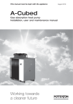
Installation, user and
maintenance manual
GAHP-A
air-water gas absorption heat pump
PRO platform
powered by gas and renewable energy
Revision: B
Code: D-LBR548
This manual has been drawn up and printed by Robur S.p.A.; whole or partial reproduction of
this manual is prohibited.
The original is filed at Robur S.p.A.
Any use of this manual other than for personal consultation must be previously authorised by
Robur S.p.A.
The rights of those who have legitimately filed the registered trademarks contained within this
publication are not affected.
With the aim of continuously improving the quality of its products, Robur S.p.A. reserves the
right to modify the data and contents of this manual without prior notice.
Installation, user and maintenance manual – GAHP-A
Index of contents
1PREFACE������������������������������������������������������������������������������������������������������������5
2OVERVIEW AND TECHNICAL CHARACTERISTICS�����������������������������������������7
2.1WARNINGS��������������������������������������������������������������������������������������������������������������������������������������������������������������������������������������� 7
2.2NOTES ON OPERATION OF THE APPLIANCE����������������������������������������������������������������������������������������������������������������������10
2.3TECHNICAL MANUFACTURING CHARACTERISTICS��������������������������������������������������������������������������������������������������������11
2.4TECHNICAL DATA������������������������������������������������������������������������������������������������������������������������������������������������������������������������11
2.5DIMENSIONS AND SERVICE PANEL���������������������������������������������������������������������������������������������������������������������������������������14
3NORMAL OPERATION������������������������������������������������������������������������������������17
3.1START UP (AND SHUT DOWN)������������������������������������������������������������������������������������������������������������������������������������������������17
3.2ON-BOARD ELECTRONICS��������������������������������������������������������������������������������������������������������������������������������������������������������19
3.3RESET OPERATIONS AND MANUAL DEFROSTING�����������������������������������������������������������������������������������������������������������21
3.4OPERATING SETTINGS���������������������������������������������������������������������������������������������������������������������������������������������������������������23
3.5PROLONGED PERIODS OF DISUSE����������������������������������������������������������������������������������������������������������������������������������������23
4HYDRAULIC SYSTEM INSTALLATION TECHNICIAN������������������������������������27
4.1GENERAL INSTALLATION PRINCIPLES����������������������������������������������������������������������������������������������������������������������������������27
4.2POSITION OF THE APPLIANCE������������������������������������������������������������������������������������������������������������������������������������������������27
4.3HYDRAULIC CONNECTIONS����������������������������������������������������������������������������������������������������������������������������������������������������30
4.4GAS SUPPLY SYSTEM�����������������������������������������������������������������������������������������������������������������������������������������������������������������32
4.5CONDENSATE DISCHARGE CONNECTION��������������������������������������������������������������������������������������������������������������������������32
4.6FILLING OF HYDRAULIC CIRCUIT�������������������������������������������������������������������������������������������������������������������������������������������34
4.7EXHAUSTING THE COMBUSTION PRODUCTS�������������������������������������������������������������������������������������������������������������������35
4.8PROGRAMMING OF HYDRAULIC PARAMETERS���������������������������������������������������������������������������������������������������������������36
5ELECTRICAL SYSTEM INSTALLATION TECHNICIAN������������������������������������39
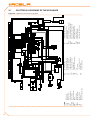
5.1ELECTRICAL DIAGRAMS OF THE APPLIANCE��������������������������������������������������������������������������������������������������������������������42
5.2HOW TO CONNECT THE APPLIANCE ELECTRICALLY�������������������������������������������������������������������������������������������������������43
5.3TYPE B (DDC)��������������������������������������������������������������������������������������������������������������������������������������������������������������������������������43
5.4TYPE C (Consent switch)�����������������������������������������������������������������������������������������������������������������������������������������������������������55
5.5HOW TO REMOTELY CONTROL THE FLAME CONTROLLER RESET������������������������������������������������������������������������������56
6INITIAL ACTIVATION AND MAINTENANCE��������������������������������������������������59
6.1PROCEDURE FOR INITIAL ACTIVATION��������������������������������������������������������������������������������������������������������������������������������59
6.2MAINTENANCE�����������������������������������������������������������������������������������������������������������������������������������������������������������������������������63
6.3CHANGE OF GAS TYPE��������������������������������������������������������������������������������������������������������������������������������������������������������������64
7ACCESSORIES��������������������������������������������������������������������������������������������������67
8APPENDIX�������������������������������������������������������������������������������������������������������69
8.1MACHINE OPERATING CODES������������������������������������������������������������������������������������������������������������������������������������������������69
3
4
Installation, user and maintenance manual – GAHP-A
1PREFACE
This Installation, user and maintenance manual is a guide to the installation and operation of the Air-Water gas absorption heat pump "GAHP-A".
This manual is specifically intended for:
• final users for the use of the appliance according to their own requirements;
• Installation technicians (hydraulic and electrical) for the carrying out of a correct
installation of the appliance.
The manual also contains:
• a section that describes all the operations necessary for the “first start-up” and for
the “gas change” of the appliance, as well as the main maintenance operations;
• an "ACCESSORIES" section with a description of accessories available and their respective reference codes.
Summary
The manual has 8 sections:
SECTION 1 is a brief introduction to the use of the manual itself.
SECTION 2 is intended for use by the final user, hydraulic and electrical installation technicians and the Robur TAC; it gives general warnings, operating instructions and constructional specifications. This section also contains technical data and dimensional drawings
of the appliance.
SECTION 3 is intended for use by the final user; it provides the information necessary to
use the appliance correctly according to the user's own requirements.
SECTION 4 is intended for use by the hydraulic installation technician; it provides the
indications necessary for the technician for the creation of the hydraulic plant, fumes
discharge and gas supply system.
SECTION 5 is intended for use by the electrical installation technician; it provides the information required to hook up the appliance electrically.
SECTION 6 is intended for use by the Robur TAC; it provides the indications necessary to
carry out the entire initial activation procedure (preliminary verification of plant compliance, initial activation, and regulation of gas flow to the burners) and the operations for
change of gas type, if required. This section includes a summary of the main maintenance
operations (checks, controls and cleaning operations to perform) to which the appliance
is subject.
SECTION 7 is intended for use by the final user, hydraulic and electrical installation technicians and the Robur TAC. it contains information about accessories available for the
appliance.
SECTION 8 is an appendix which lists the appliance's operating codes and associated
instructions in tabular form.
References
If the appliance is to be connected to a Direct Digital Controller (DDC), refer to the following documentation with which it is supplied:
INSTALLATION TECHNICIAN MANUAL - book 1: for installation/service technicians
FINAL USER MANUAL - book 2: for the final user of the DDC
Definitions, terms and icons
APPLIANCE: this term refers to the Air-Water gas absorption heat pump "GAHP-A".
CCP: "Comfort Control Panel".
CCI: "Comfort Control Interface" device.
5
DDC: digital control panel (Direct Digital Controller).
TAC: Technical Assistance Centre (authorised by Robur S.p.A.).
The icons present in the margin of the manual have the following meanings:
= DANGER
= WARNING
= NOTE
= START OF OPERATING PROCEDURE
= REFERENCE to another part of the manual or other document
6
Installation, user and maintenance manual – GAHP-A
2OVERVIEW AND TECHNICAL CHARACTERISTICS
In this section, for all users, you will find general warnings, the operating principle of the
appliance and its manufacturing characteristics. This section also contains technical data
and dimensional drawings of the appliance.
2.1WARNINGS
This manual constitutes an integral and essential part of the product and must be delivered to the user together with the appliance.
Conformity to CE standards
The absorption heat pumps of the GAHP series are certified as conforming to standard EN
12309-1 and -2 and comply with the essential requirements of the following Directives:
• Gas Directive 90/396/EEC and subsequent modifications and additions.
• Efficiency Directive 92/42/EEC and subsequent modifications and additions.
• Electromagnetic Compatibility Directive 89/336/EEC and subsequent modifications and additions.
• Low Voltage Directive 89/336/EEC and subsequent modifications and additions.
• “Machinery Directive” 2006/42/EC.
• Pressurised Equipment Directive 97/23/EEC and subsequent modifications and
additions.
• UNI EN 677 Specific requisites for condensation boilers with nominal thermal capacity no greater than 70 kW.
The absorption heat pumps of the GAHP series emit values of nitrogen oxide (NOx) less
than 60 mg/kWh in line with the prescriptions of the RAL UZ 118 "Blauer Engel".
Information regarding the above EC certifications is given in Paragraph 2.4 TECHNICAL
DATA → 11, as well as on the Nameplate of the appliance itself.
Safety
The appliance must only be used for the purposes for which it has been designed. Any
other use is considered inappropriate and therefore dangerous. The manufacturer does
not accept any contractual or extra-contractual liability for any damage caused by improper use of the appliance.
Do not operate the appliance if, at the moment it is to be used, dangerous conditions
arise: odour of gas in the circuit or near to the appliance; problems with the electrical/gas
mains or hydraulic circuit; parts of the appliance submerged in water or otherwise damaged; control and safety components bypassed or defective. Ask professionally qualified
personnel for assistance.
If you smell gas:
•
•
•
o not operate electrical devices in the vicinity of the appliance, such as telephones,
d
multimeters or other equipment that can cause sparks;
shut off the gas supply by means of the appropriate gas tap;
cut off electrical power to the appliance by means of the external disconnecting
switch that the electrical system installation technician has provided in the appropriate panel;
7
•
r equest the assistance of professionally qualified personnel from a telephone far
from the appliance.
The appliance has a sealed circuit that may be classified as a pressurised container, i.e.
with internal pressure higher than atmospheric pressure. The fluids contained in its
sealed circuits are harmful if swallowed or inhaled, or if they come into contact with the
skin. Do not carry out any operation on the sealed circuits of the appliance or on the
valves present.
Packing items (plastic bags, polystyrene foam, nails, etc.) must be kept out of the reach of
children, as they represent potential sources of danger.
The electrical safety of this appliance is assured only when it is correctly connected to an
effective grounding system, as detailed in current electrical safety norms.
Installation and regulatory references
When the appliance arrives at the installation site, before beginning the stages required
to move it in order to position it on the site, perform a visual check to ascertain that there
are no evident signs of breakage or damage to the packaging or to the external panels,
which would be signs that damage occurred during transport.
Packing materials must be removed only after the appliance has been positioned on site.
After removing the packing materials, ensure that the appliance is intact and complete.
Installation of the appliance may only be carried out by firms that are qualified in accordance with current legislation in the country of installation, i.e. by professionally qualified
personnel.
"Professionally qualified personnel" means personnel with specific technical competence
in the sector of heating/cooling plants and gas appliances.
Installation of the appliance must be carried out in compliance with current local and
national regulations regarding the design, installation and maintenance of heating and
cooling plants in accordance with the manufacturer's instructions.
In particular, current regulations regarding the following must be observed:
• Gas equipment.
• Electrical equipment.
• Heating installations and heat pumps
• Every other standard and regulation that concerns the installation of equipment
for summer and winter air conditioning using gas fuel.
The manufacturer does not accept any contractual or extra-contractual liability for any
damage caused by errors in installation and/or failure to observe the abovementioned
regulations and the instructions supplied by the manufacturer itself.
Once the appliance is installed
The firm that has undertaken the installation must provide the owner with a declaration that the installation has been carried out in compliance with proper workmanship
practices, current national and local regulations, and the instructions supplied by Robur
S.p.A.
Before contacting your authorised Robur Technical Assistance Centre (TAC) for the initial
activation, the firm must ensure that:
8
Installation, user and maintenance manual – GAHP-A
•
•
•
•
•
t he electricity and gas mains specifications correspond to the specifications on the
nameplate;
the mains gas pressure falls within the range of values specified in Table 6.1 Network gas pressure → 61;
the gas supplied to the appliance is of the type for which it is designed;
the gas supply system and water distribution system are sealed;
the gas and electricity supply systems are correctly rated for the capacity required
by the appliance and that they are equipped with all safety and control devices
prescribed by current regulations
Check that no safety and control devices are excluded, by-passed or not working
correctly.
Initial activation procedure
The entire procedure for the first activation of the appliance must be carried out exclusively by an authorized Robur Technical Assistance Centre (TAC) and according to the
instructions supplied by the manufacturer.
To carry out entire procedure correctly, follow the instructions in Paragraph 6.1 PROCEDURE FOR INITIAL ACTIVATION → 59.
Contact your local Authorised Robur Technical Assistance Centre (TAC). To find out who
your local TAC is, contact Robur S.p.A. (tel. +39 035 888.111). The guarantee could be
voided if the initial activation is not carried out (and validated) by a Robur TAC.
Operation and maintenance of the appliance
To ensure the correct operation of the appliance and to avoid failures, control of the
switching on and off of the appliance must be done in line with the requirements of the
various types of installation.
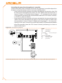
• If the appliance is connected to the DDC (see Figure 5.3 Direct Digital Control
(DDC) → 41), the appliance may be switched on and off exclusively by the DDC
itself.
• If the appliance is NOT connected to a Direct Digital Control (DDC) the appliance
may be switched on and off exclusively by a switch on the consent circuit.
The appliance must never normally be switched on and off by shutting off the power
supply upstream of the Controle Device (CCP, DDC or consent switch) before having used
the latter first and waited for the shutdown cycle to end (approximately 7 minutes). The
shutdown cycle terminates when the hydraulic pump switches off (no parts in motion).
Shutting off the power supply while the appliance is running can irreparably damage its
internal components!
If the appliance fails to operate correctly, with the consequent indication of the Machine
code, follow the instructions of Paragraph 8.1 MACHINE OPERATING CODES → 69.
In the event of failure of the appliance and/or breakage of any of its parts, refrain from
any attempt to repair and/or restore operation of the appliance through direct action.
9
•
eactivate the appliance immediately (if permitted and if no condition of danger
d
exists) by starting the shutdown cycle via the CCP (or DDC or consent switch) and
waiting for it to terminate (approximately 7 minutes);
• disconnect the appliance from the gas and electricity mains, cutting off gas supply
by means of the appropriate valve and the power supply by means of the external
circuit breaker provided by the electrical system installation technician on the appropriate panel.
Correct routine maintenance ensures the efficiency and good operation of the appliance over time.
Carry out maintenance operations according to the instructions supplied by the
manufacturer.
For maintenance of the appliance’s internal components, contact a Robur TAC
or qualified technician; for other maintenance requirements, see Paragraph 6.2
MAINTENANCE → 63.
Any repair of the appliance must be carried out by an authorised Robur Technical Assistance Centre (TAC), using only original parts.
Failure to observe the indications given above may compromise the operation and safety
of the appliance, and may invalidate its guarantee, if active.
If the appliance is to be disposed of, contact Robur S.p.A. for its correct disposal.
If the appliance is to be sold or transferred to another owner, ensure that this “Installation, user and maintenance manual” is handed over to the new owner and installation
technician.
2.2NOTES ON OPERATION OF THE APPLIANCE
The appliance uses the water/ammoniac absorption thermodynamic cycle (H20 – NH3) to
produce hot water, using atmospheric air as renewable energetic source.
The water/ammoniac thermodynamic cycle used on the unite GAHP-A, is implemented
in a hermitically sealed circuit which has no mechanical unions and is checked directly
by manufacturer to ensure the perfect seal of all joints, thus making refrigerant top ups
completely unnecessary.
Description and general characteristics
The air-water gas absorption heat pump GAHP-A is available in the following versions:
• Version HT: optimised for high temperature heating systems (radiators, fan coils);
it produces hot water to +65°C for heating purposes and up to +70°C for sanitary
hot water.
• Version LT: optimised for low temperature floor heating systems; it produces hot
water to +55°C for heating purposes and up to +70°C for sanitary hot water.
The GAHP heat pump can be controlled with the Direct Digital Control (vedere Figura 5.3
Direct Digital Control (DDC) → 41) or with a switch on the consent circuit.
During operation, combustion products are exhausted via the discharge terminal at the
left side of the appliance (see Figure 2.1 Size (Standard ventilation) → 14 or Figure 2.2
Size → 15). The fumes outlet must be connected to a flue (for further details, see Paragraph 4.7 EXHAUSTING THE COMBUSTION PRODUCTS → 35).
The appliance is powered with 230 Vac 1N - 50 Hz.
10
Installation, user and maintenance manual – GAHP-A
2.3TECHNICAL MANUFACTURING CHARACTERISTICS
The appliance is supplied with the following technical manufacturing characteristics,
control and safety components:
• Steel sealed circuit, treated on the outside with epoxy paint.
• Sealed combustion chamber suited for type C installation.
• Metal mesh irradiation burner equipped with ignition and flame detection managed by an electronic control unit.
• Tube coil heat recovery (AISI 304L ).
• Air-based heat exchanger with single-position finned coil, manufactured in steel
tubing and aluminium fins.
• Titanium stainless steel tube bundle water exchanger, with external insulation.
• Automatic two-way microprocessor-controlled defrosting valve, allowing the
finned coil to be defrosted.
Control and safety components
• S61 controller with integrated microprocessor and LCD display and control knob,
complete with "Mod10" supplementary combustion modulation controller (see
Figure 5.1 Electronic board S61 → 39 and Figure 5.2 Mod10 controller → 41).
• Plant water flowmeter.
• Sealed circuit high temperature limit thermostat, manual reset.
• Flue temperature limit switch, automatic reset.
• Flue temperature thermostat 120 °C, manual reset.
• Sealed circuit safety relief valve.
• Safety by-pass valve, between high and low pressure sealed circuit.
• Antifreeze function for hydronic system.
• Ionization flame control box.
• Double shutter electric gas valve.
• Condensate siphon icing sensor.
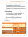
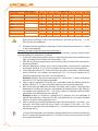
2.4TECHNICAL DATA
Table 2.1 – GAHP-A LT technical data
GAHP-A LT
GAHP-A LT S
OPERATION WHEN HEATING
OPERATING POINT A7W50
OPERATING POINT A7W35
Thermal capacity
G.U.E. gas usage efficiency
Thermal power
G.U.E. gas usage efficiency
Thermal power
Nominal (1013 mbar - 15°C)
true peak
NOx emission class
NOx emission
CO emission
Hot water delivery temperature
Hot water return temperature
Hot water flow rate
Hot water pressure drop
Ambient air temperature (dry bulb)
Thermal differential
maximum for heating
maximum for ACS
maximum heating
maximum for ACS
minimum
nominal
maximum
minimum
nominal water pressure
(A7W50)
maximum
minimum
nominal
%
kW
%
kW
kW
kW
ppm
ppm
°C
°C
°C
°C
°C
l/h
l/h
l/h
151 (1)
34,9 (1)
165
38,4
25,7
25,2
5
25
36
55
70
45
60
2
3000
4000
1000
bar
0,43 (2)
°C
°C
°C
45
-20 (7)
10
11
GAHP-A LT
gas consumption
methane G20 (nominal)
G30 (nominal)
G31 (nominal)
GAHP-A LT S
m3/h
kg/h
kg/h
2,72 (3)
2,03 (4)
2,00 (4)
V
230
SINGLE PHASE
ELECTRICAL SPECIFICATIONS
Voltage
TYPE
Power supply
Frequency
Electrical power absorption
Degree of protection
INSTALLATION DATA
Level of acoustic pressure at 10 meters (maximum)
Minimum storage temperature
Maximum operating pressure
Water content inside the apparatus
nominal
IP
Gas fitting
Fume outlet
Maximum condensation water flow rate
Size
Weight
GENERAL INFORMATION
INSTALLATION MODE
width
height
depth
In operation
AMMONIA R717
WATER H2O
COOLING FLUID
MAXIMUM PRESSURE OF THE COOLING CIRCUIT
50
0,90 (5)
1,09 (5)
X5D
dB(A)
°C
bar
l
TYPE
thread
TYPE
thread
Size
Residual head
Water fitting
50 Hz
supply
kW
54 (8)
48 (8)
-30
4
4
F
1 1/4
F
3/4
80
80
4
848 (6)
"G
"G
mm
Pa
l/h
mm
mm
mm
kg
kg
kg
bar
1281 (6)
1537 (6)
1258
390
400
B23P, B33, B53P
7
10
35
Notes:
1. In compliance with EN12309-2 Standard evaluated on real lower heating capacity
weakened with respect to the nominal value. For functioning conditions different
to the nominal ones, refer to the PRO platform design manual.
2. For flow rates different to the nominal refer to the PRO platform Design Manual.
3. PCI 34.02 MJ/m3 (1013 mbar – 15 ° C).
4. PCI 46.34 MJ/kg (1013 mbar – 15 ° C).
5. ± 10% depending on power voltage and absorption tolerance of electric motors.
6. Overall dimensions excluding fumes pipes (see Figure 2.1 Size (Standard ventilation) → 14 and Figure 2.2 Size → 15).
7. It's possible to have a special configuration for operation to -30 °C (as an
optional).
8. Free field, frontal, directionality factor 2.
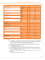
Table 2.2 – GAHP-A HT technical data
GAHP-A HT
GAHP-A HT S
OPERATION WHEN HEATING
OPERATING POINT A7W50
OPERATING POINT A7W65
OPERATING POINT A-7W50
Thermal capacity
NOx emission class
NOx emission
CO emission
12
G.U.E. gas usage efficiency
Thermal power
G.U.E. gas usage efficiency
Thermal power
G.U.E. gas usage efficiency
Thermal power
Nominal (1013 mbar - 15°C)
true peak
%
kW
%
kW
%
kW
kW
kW
ppm
ppm
152 (1)
35,4 (1)
119
27,5
125
31,5
25,7
25,2
5
25
36
Installation, user and maintenance manual – GAHP-A
GAHP-A HT
Hot water delivery temperature
Hot water return temperature
Hot water flow rate
Hot water pressure drop
Ambient air temperature (dry bulb)
Thermal differential
gas consumption
maximum for heating
maximum for ACS
maximum heating
maximum for ACS
minimum
nominal
maximum
minimum
nominal water pressure
(A7W50)
maximum
minimum
nominal
methane G20 (nominal)
G30 (nominal)
G31 (nominal)
GAHP-A HT S
°C
°C
°C
°C
°C
l/h
l/h
l/h
65
70
55
60
2
3000
4000
1000
bar
0,43 (2)
°C
°C
°C
m3/h
kg/h
kg/h
45
-20 (7)
10
2,72 (3)
2,03 (4)
2,00 (4)
V
230
SINGLE PHASE
50 Hz
supply
kW
50
ELECTRICAL SPECIFICATIONS
Voltage
TYPE
Power supply
Frequency
Electrical power absorption
Degree of protection
INSTALLATION DATA
Level of acoustic pressure at 10 meters (maximum)
Minimum storage temperature
Maximum operating pressure
Water content inside the apparatus
nominal
IP
Gas fitting
Fume outlet
Maximum condensation water flow rate
Size
Weight
GENERAL INFORMATION
INSTALLATION MODE
width
height
depth
In operation
AMMONIA R717
WATER H2O
COOLING FLUID
MAXIMUM PRESSURE OF THE COOLING CIRCUIT
1,09 (5)
X5D
dB(A)
°C
bar
l
TYPE
thread
TYPE
thread
Size
Residual head
Water fitting
0,90 (5)
54 (8)
"G
"G
mm
Pa
l/h
mm
mm
mm
kg
kg
kg
bar
48 (8)
-30
4
4
F
1 1/4
F
3/4
80
80
4
848 (6)
1281 (6)
1537 (6)
1258
390
400
B23P, B33, B53P
7
10
35
Notes:
1. In compliance with EN12309-2 Standard evaluated on real lower heating capacity
weakened with respect to the nominal value. For functioning conditions different
to the nominal ones, refer to the PRO platform design manual.
2. For flow rates different to the nominal refer to the PRO platform Design Manual.
3. PCI 34.02 MJ/m3 (1013 mbar – 15 ° C).
4. PCI 46.34 MJ/kg (1013 mbar – 15 ° C).
5. ± 10% depending on power voltage and absorption tolerance of electric motors.
6. Overall dimensions excluding fumes pipes (see Figure 2.1 Size (Standard ventilation) → 14 and Figure 2.2 Size → 15).
7. It's possible to have a special configuration for operation to -30 °C (as an
optional).
8. Free field, frontal, directionality factor 2.
13
Table 2.3 – PED data
GAHP-A LT
GAHP-A HT
GAHP-A LT S
PED data
COMPONENTS UNDER
PRESSURE
Generator
Leveling chamber
Evaporator
Cooling volume transformer
Cooling absorber solution
Solution pump
TEST PRESSURE (IN AIR)
SAFETY VALVE PRESSURE CALIBRATION
FILLING RATIO
l
l
l
l
l
l
bar g
bar g
kg of
NH3/l
FLUID GROUP
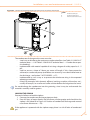
2.5DIMENSIONS AND SERVICE PANEL
Figure 2.1 – Size (Standard ventilation)
Front and side views (dimensions in mm).
14
18,6
11,5
3,7
4,5
6,3
3,3
55
35
0,146
GROUP 1°
GAHP-A HT S
Installation, user and maintenance manual – GAHP-A
Figure 2.2 – Size
Front and side views (dimensions in mm).
Figure 2.3 – Service plate
LEGEND
GGas fitting Ø ¾” F
IInlet water fitting Ø 1¼” F
OOutlet water fitting Ø 1¼” F
Hydraulic/gas unions detail
15
16
Installation, user and maintenance manual – GAHP-A
3NORMAL OPERATION
In this section you will find all the indications necessary for the activation, regulation and
control of operation of the appliance depending on the type of installation and control
setup.
• TYPE
A (NOT APPLICABLE at PRO Platform): controlled by Comfort Control
Panel.
• TYPE
B: controlled by DDC (see Figure 5.3 Direct Digital Control (DDC) → 41).
• TYPE
C: controlled by consent switch (e.g. on-off switch, ambient thermostat, timer, etc.).
3.1START UP (AND SHUT DOWN)
Efficient operation and long life of the appliance depend largely on its correct use!
Before activating the appliance, check that:
• the gas valve is open;
• the appliance is powered electrically;
• the CCP/DDC are electrically powered;
• the installation technician has ensured that the hydraulic circuit is supplied in the
correct conditions.
If these conditions are satisfied, it is possible to proceed with activation.
Type A: appliance connected to Comfort Control Panel (CCP)
Type NOT APPLICABLE at PRO platform.
Type B: appliance connected to a Direct Digital Controller (DDC)
If the appliance is connected to a Direct Digital Controller (see Figure 5.3 Direct Digital
Control (DDC) → 41) and the DDC is in controller mode, activation and control of the
appliance will occur exclusively by operating the DDC. In this case, refer to the manual
supplied with it.
The appliance must never normally be switched on and off by shutting off the power
supply upstream of the DDC before having used the latter first and waited for the shut
down cycle to end (approximately 7 minutes). The shutdown cycle terminates when the
hydraulic pump switches off (no parts in motion).
Shutting off the power supply while the appliance is running can irreparably damage its
internal components!
Type C: standalone appliance
Standalone appliances must be activated and deactivated only by means of the consent
switch provided by the electrical installation technician.
According to requirements, this consent switch may be an on/off button, an ambient
thermostat, a programmable timer, or one or more voltage free contacts controlled by
another process. For details about the type of on/off command installed, contact the
plant’s electrical installation technician.
The appliance must never normally be switched on and off by shutting off the power
supply upstream of the Controle Device (CCP, DDC or consent switch) before having used
the latter first and waited for the shutdown cycle to end (approximately 7 minutes). The
shutdown cycle terminates when the hydraulic pump switches off (no parts in motion).
17
Shutting off the power supply while the appliance is running can irreparably damage its
internal components!
Start up
Switch on the appliance by means of the on/off command (placing it in the "ON"
position).
When activation is successful, the appliance is managed by the S61 controller in its electrical panel (see paragraph 3.2 ON-BOARD ELECTRONICS → 19). The controller’s display
may be viewed through the viewing hole on the front panel of the unit itself.
During operation, the S61 controller displays operating codes.
If the appliance remains inactive for a prolonged period, it is possible that air is present
in the gas pipes. In this case, activation fails and the appliance reports the operating
code: "u412" - flame controller arrest (temporary) (see Paragraph 8.1 MACHINE OPERATING CODES → 69) and after a brief interval the appliance automatically launches the start
up procedure again. If code u 412 is signalled 4 times on successive activation attempts,
the code persists, the appliance locks out the flame controller and displays the following
operating code: "E412" – flame controller arrest (see Paragraph 8.1 MACHINE OPERATING
CODES → 69). In this case reset is not automatic.
To restore operation of the appliance, carry out a reset of the flame control unit via menu
2 of the controller: the procedure is illustrated in Paragraph 3.3 RESET OPERATIONS AND
MANUAL DEFROSTING → 21. After it is reset, the appliance will make a new attempt to
activate.
If the appliance locks out several times, contact a Robur TAC by calling the Technical Service Department of Robur S.p.A. (tel. 035 888.111).
Shut down
Switch off the appliance via the on/off command (placing it in the "OFF" position).
The shutdown cycle takes approximately 7 minutes to complete.
VISUALISING AND RESETTING OPERATING CODES
Operating codes can be generated:
• by the S61 on-board controller;
• by the CCP/DDC (if present).
The operating codes generated by the S61 controller are displayed on its screen and can
also be viewed on the CCI (if present) or DDC (if present).
Operating codes generated by the controller can be cleared through the board itself or
from the CCI/DDC (if fitted and allowed).
For a description of operating codes generated by the controller and how to clear them,
refer to the list of operating codes contained in Paragraph 8.1 MACHINE OPERATING
CODES → 69.
The controller (see Figure 5.1 Electronic board S61 → 39) is located inside the electrical
panel of the appliance and the display may be viewed through the viewing hole on the
front panel of the unit itself.
The Machine Codes generated by the CCI/DDC may only be viewed on the display of the
CCI/DDC and may be cleared only through the CCI/DDC.
18
Installation, user and maintenance manual – GAHP-A
For the operating codes generated by the CCP/DDC, refer to the manuals supplied with
the unit.
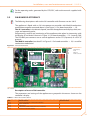
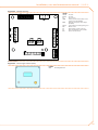
3.2ON-BOARD ELECTRONICS
The following descriptions refer to the S61 controller with firmware version 3.015.
The appliance is fitted with an S61 microprocessor controller with Mod10 combustion
modulation controller mounted above it (see Figure 3.1 On-board controller → 19).
The S61 controller, in the electrical panel, controls the appliance and displays data, messages and operating codes.
Programming, control and monitoring of the appliance take place by interacting with
the display A and knob B shown in Figure 3.1 On-board controller → 19. La porta CAN
The CAN BUS port connects one or several appliances to the CCP (if present) or a DDC (if
present).
The Mod10 controller (see detail D in Figure 3.1 On-board controller → 19) is used for
combustion modulation.
Figure 3.1 – On-board controller
LEGEND
A4 digit display
BKnob
CCAN port
DMod10 controller
S61 + Mod10
Description of menu of S61 controller
The parameters and settings of the appliance are grouped in the menus shown on the
controller’s display:
Table 3.1 – Menu of electronic board
MENU
Menu 0
Menu 1
Menu 2
Menu 3
Menu 4
MENU DESCRIPTION
VIEW DATA (TEMPERATURE, VOLTAGE, PUMP SPEED, ECC...)
VIEW ALL PARAMETERS
ENTER ACTIONS
USER SETTINGS (THERMOSTATING, SET-POINT, T. DIFFERENTIAL)
INSTALLATION TECHNICIAN SETTINGS
THE DISPLAY SHOWS
0.
1.
2.
3.
4.
19
MENU
Menu 5
Menu 6
Menu 7
Menu 8
E
MENU DESCRIPTION
TECHNICAL ASSISTANCE CENTRE SETTINGS
TECHNICAL ASSISTANCE CENTRE SETTINGS (MACHINE TYPE)
VIEW DIGITAL IMPUTS
(MENU NOT USED)
(EXIT MENU)
THE DISPLAY SHOWS
5.
6.
7.
8.
E.
Menu list of electronic board
Menus 0, 1 and 7 are Viewing Menus: they only allow the information displayed to be
read, and not modified. Via menu 0 it is possible to view the appliance operating data as
detected by the board in real time; Menu 1 shows the parameters that characterise the
operation of the appliance and their current values.
Menu 7 pertains exclusively to Robur's authorized Technical Assistance Centres.
To view the information contained in these menus, proceed as illustrated in the paragraph "How to acces the menus".
Menu 2 is an execution menu: it is used to reset the flame controller, reset errors and
manual defrosting control.
To perform these procedures, see Paragraph 3.3 RESET OPERATIONS AND MANUAL
DEFROSTING → 21.
Menu 3 is a settings menu: it allows the values displayed to be set. The correct values of
these parameters, for optimum performance of the appliance with the plant to be used
connected, have already been set during installation. In any case, to set new values for
the parameters, see Paragraph 4.8 PROGRAMMING OF HYDRAULIC PARAMETERS → 36.
Menus 4, 5, 6 and 7 exclusively concern the installation technician and Robur’s authorized Technical Assistance Centre.
Menu 8 may currently be selected, but not used.
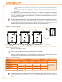
Display and knob
The controller’s display can be viewed through the glass of the viewing aperture on the
front panel of the appliance.
Upon activation, all of the LEDs of the display light up for approximately three seconds,
and then the name of the board, S61, appears. After around 15 seconds after the appliance powers up, the appliance starts running if the required consent is available.
During correct operation the display shows, alternately, the following information: outlet
water temperature, inlet water temperature, and the difference between the two water
temperatures (see Table 3.2 Operating information → 20).
Table 3.2 – Operating information
OPERATING MODE: HEATING
PARAMETER
Hot outlet water temperature
Hot inlet water temperature
Differential temperature (outlet - inlet)
THE DISPLAY SHOWS
50.0
40.0
10.0
Example of data visualised on display: water temperature and differential
If there are operating problems, the display shows, sequentially, the operating codes corresponding to the problem detected. A list of these codes with their description and the
procedure to follow to bring the appliance back to correct operation is provided in Paragraph 8.1 MACHINE OPERATING CODES → 69.
The knob is used to display or set parameters, or to execute actions/commands (e.g.: a
function or reset), when permitted.
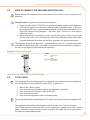
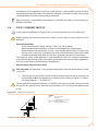
HOW TO ACCESS THE MENUS
• To use the knob with the special key supplied with the appliance:
20
Installation, user and maintenance manual – GAHP-A
You will need: the appliance's electrical power switches set to "ON"; the controller's display sequentially shows the operating data (temperature, delta T) regarding the current
mode (e.g.: heating) and any active operating codes ("u/E...").
1. R
emove the front panel by removing the fixing screws.
2. Remove the cover of the electrical panel to access the knob.
3. Use the special key through the hole to operate the knob and access the controller’s menus and parameters.
4. To display the menus just press the knob once: the display shows the first menu:
"0." (= menu 0).
5. The display shows “0.”. To display the other menus, turn the knob clockwise; The
display will read, in order: "1.", "2.", "3.", "4.", "5.", "6.", "7.", "8." and "E" (see Table 3.1
Menu of electronic board → 19).
6. To display the parameters in a given menu (for example, menu 0), turn the knob
until it displays the menu in question (in the example: "0.") and press the knob: the
display will show the first of the menu’s parameters, in this example "0.0" or "0.40"
(= menu 0, parameter "0" or "40").
7. In the same way: turn the knob to scroll through content (menus, parameters, actions), press the knob to select/confirm the content (access a menu, display/set
a parameter, execute an action, quit or return to the previous level). For example,
to quit the menus, turn the knob to scroll through menus "0.", "1.", "2." etc. until the
controller displays the quit screen "E"; now press the knob to quit.
In the case of menus 0 and 1, the user can view any parameter. For information about
menu 2, refer to Paragraph 3.3 RESET OPERATIONS AND MANUAL DEFROSTING → 21. To
set the parameters of menu 3, refer to Paragraph 4.8 PROGRAMMING OF HYDRAULIC PARAMETERS → 36. The other menus are not for the User: the information in these menus is
dealt with in the sections dedicated to the installation technician or Robur TAC.
The special key allows the knob of the electronic board to be operated without opening
the cover of the electrical panel, so that operators are protected from live components.
When the necessary settings have been completed, put away the special key, replace the
cap on the aperture of the electrical panel and refit the front panel of the appliance.
3.3RESET OPERATIONS AND MANUAL DEFROSTING
There are several possible reasons why the appliance may have error status and therefore
its operation arrested; such an error situation does not necessarily correspond to damage
or malfunction on the part of the appliance. The cause that has generated the error may
be temporary: for example, presence of air in the gas supply line or temporary power
failure.
The appliance can be reset with controller menu 2, the Comfort Control Panel (if present)
or the DDC (if present). In these two latter cases, refer to their documentation.
Reset appliance controller
The Table 3.3 Menu 2 → 22 shows the actions available in menu 2.
For regulatory reasons, the flame controller reset is in a dedicated voice of menu.
21
Table 3.3 – Menu 2
ACTION
20
21
22
23
24
25
E
REQUIRED FOR EXECUTION
Reset flame controller arrest
Reset other operating codes
Manual defrost
Timed forcing to minimum power
Timed forcing to maximum power
Regulation of power
(EXIT MENU)
SHOWN ON DISPLAY AS
2. 20
2. 21
2. 22
2. 23
2. 24
2. 25
2. E
The general operating codes of the controller can be reset with functions "20" and "21".
Actions "23", "24" and "25" are used to regulate the combustion parameters or for gas type
changeovers, and are thus for use only by the installation technician or Robur TAC (for
other information refer to Paragraph 6.1 PROCEDURE FOR INITIAL ACTIVATION → 59).
ACTION "20"
Reset flame controller arrest; this may be used when the appliance is first activated, see
Paragraph 3.1 START UP (AND SHUT DOWN) → 17, when the appliance is in a permanent
locked condition or after a long period of disuse (see Paragraph 3.5 PROLONGED PERIODS OF DISUSE → 23).
You will need: access to the electrical panel, see Paragraph "Display and knob".
To reset the flame control unit select menu 2, as indicated in the Paragraph "Accessing
the Menus"; then proceed as follows:
1. The display shows: "2." press the knob to access the menu. The display initially
shows item "2. 20".
2. Press the knob to display the flashing reset request: "reS1".
3. Press the knob again to reset the flame controller. The reset request stops flashing,
and again the display shows "2. 20". The reset operation has been performed.
4. To quit the menu, turn the knob clockwise until the "2. E" is displayed. Now press
the knob to return to menu selection: "2.".
5. To exit the menu selection and return to the normal visualisation of the parameters
of the appliance, turn the knob clockwise until "E" displays; press the knob to quit.
ACTION "21"
Reset other warnings/errors; this is required to reset any warnings and errors that may
occur during operation of the appliance.
You will need: access to the electrical panel, see Paragraph “Display and knob”.
To reset the controller errors, select menu 2, as indicated in the Paragraph "Accessing the
Menus"; Then:
1. The display shows: "2." press the knob to access the menu. The display initially
shows item "2. 20".
2. Turn the knob clockwise to display item "2. 21".
3. Press the knob to display the flashing reset request: "rEr1".
4. Press the knob again to perform a board error reset. The reset request stops flashing, and the again display shows "2. 21". The reset operation has been performed.
5. To quit the menu, turn the knob clockwise until the "2. E" is displayed. Now press
the knob to return to menu selection: "2.".
6. To exit the menu selection and return to the normal visualisation of the parameters
of the appliance, turn the knob clockwise until "E" displays; press the knob to quit.
ACTION "22"
22
Installation, user and maintenance manual – GAHP-A
Manual defrosting; the execution of the manual defrosting command, provided that the
conditions exist (these are verified electronically), allows the fan coil to be defrosted,
overriding software control regarding the timing of this operation.
Defrosting mode is managed automatically by the on-board electronics and is activated
only under specific operating conditions (the on-board electronics verify the appropriate
requirements).
You will need: access to the electrical panel, see Paragraph “Display and knob”.
To execute the manual defrosting command, select menu 2 as described in the Paragraph "how to access the menus", then proceed as follows:
1. The display shows: "2." press the knob to access the menu. The display initially
shows item "2. 20".
2. Turn the knob clockwise to display "2. 22".
3. Press the knob to display the manual defrosting flashing request: "deFr".
4. Press the knob again to execute the command. The manual defrosting request
stops flashing, and the again display shows "2. 22". The manual defrosting opera
tion has been performed (if the appropriate requirements are satisfied).
5. To quit the menu, turn the knob clockwise until the "2. E" is displayed. Now press
the knob to return to menu selection: "2.".
6. To exit the menu selection and return to the normal visualisation of the parameters
of the appliance, turn the knob clockwise until "E" displays; press the knob to quit.
3.4OPERATING SETTINGS
The operations described require basic knowledge of the plant installed and of the S61
controller fitted to the appliance; before proceeding, you must acquire this information,
Paragraph 3.2 ON-BOARD ELECTRONICS → 19.
At the moment of installation, the appliance is set up by the installation technician for
best operation according to the type of plant installed. Subsequently it is possible to
modify the operating parameters, but this is not recommended if not in possession of
the necessary knowledge and experience in order to do so. In any case, to set new operating parameters for the appliance see Paragraph 4.8 PROGRAMMING OF HYDRAULIC
PARAMETERS → 36.
3.5PROLONGED PERIODS OF DISUSE
When the appliance is to be inactive for a long period, it is necessary to disconnect the
appliance before the period of disuse and reconnect it before it is used again.
To carry out these operations, contact a reputable hydraulic system installation
technician.
Disconnecting the appliance
You will need: the appliance connected to the power/gas supply. Necessary equipment
and materials.
1. I f the appliance is in operation, switch it off with the CCP (if present) or DDC (if
present), or the consent switch and wait for the shutdown cycle to terminate completely (approximately 7 minutes).
23
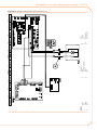
2. D
isconnect the appliance from the power supply, putting the external disconnection switch in the OFF position (see GS in Figure 5.5 Electrical wiring diagram → 43)
provided in the appropriate panel by the installation technician.
3. Close the gas valve.
Do not leave the appliance connected to power and gas supply if it is expected to remain
inactive for a long period.
If you wish to disconnect the appliance during the winter, one of the following three
conditions must be met:
1. make sure that the hydraulic plant connected to the appliance contains an adequate percentage of glycol antifreeze (see Paragraph 4.6 FILLING OF HYDRAULIC
CIRCUIT → 34 and Table 4.2 Percentage of monoethylene glycol → 35);
2. empty the hydraulic circuit completely: for this purpose the plant must be provided with water drainage points that are adequately equipped, sized and located,
to allow the water present in the circuit to drain away completely and to allow the
correct disposal of any glycol antifreeze present. For these operations, contact a
reputable hydraulic system installation technician;
3. activate the antifreeze function, which runs the circulation pumps and the appliance under 6°C. To do this, contact your hydraulic system installation technician.
This function requires the appliance to be ALWAYS powered up (electricity and
gas) and power failures excluded.Otherwise the manufacturer declines all contractual and extra-contractual liability for consequent damage.
Connecting the appliance before it is used again (to be carried out by the instal
lation technician)
Before starting this procedure, the hydraulic system installation technician must:
• ascertain whether the appliance requires any maintenance operations (contact your authorised Robur Technical Assistance Centre or consult Paragraph 6.2
MAINTENANCE → 63);
• fill the hydraulic circuit if it has been emptied, carrying out the instructions given
in Paragraph 4.6 FILLING OF HYDRAULIC CIRCUIT → 34;
• if the hydraulic circuit has not been emptied, check that the water content of the
plant is correct; if necessary, top up the circuit to at least the minimum quantity
(see Paragraph 4.6 FILLING OF HYDRAULIC CIRCUIT → 34);
• if necessary add, to the water of the system (free of impurities), inhibited monoethylene glycol antifreeze in a quantity in proportion to the MINIMUM winter
temperature in the area of installation (see Table 4.2 Percentage of monoethylene
glycol → 35);
• bring the plant to the correct pressure, making sure that the pressure of the water
in the plant is not less than 1 bar and not over 2 bar;
You will need: the appliance disconnected from the electricity/gas supply
1. open the plant gas supply valve to the appliance and make sure that there is no
smell of gas (indicating possible leaks);
2. If no smell of gas is detected, connect the appliance to the electricity supply mains
via the external circuit breaker provided by the installation technician in the appropriate panel (set the "GS" circuit breaker to the "ON" position, see Figure 5.5
Electrical wiring diagram → 43);
3. power up the CCP (if present) or DDC (if present);
4. check that the hydraulic circuit is charged;
24
Installation, user and maintenance manual – GAHP-A
5. c heck that the condensate siphon is NOT empty or blocked (see Paragraph 4.5
CONDENSATE DISCHARGE CONNECTION → 32);
6. check that the air/fumes pipes are not blocked.
7. switch on the appliance by means of the on/off command (or DDC if present and
in control mode, or via CCP, if present).
25
26
Installation, user and maintenance manual – GAHP-A
4HYDRAULIC SYSTEM INSTALLATION TECHNICIAN
In this section you will find all the instructions necessary for installing the appliance from
a hydraulic viewpoint.
Before proceeding with operations to create the hydraulic and gas supply plant of the appliance, the professionally qualified personnel concerned are advised to read Paragraph
2.1 WARNINGS → 7: it provides important information regarding installation safety and
references to current regulations.
4.1GENERAL INSTALLATION PRINCIPLES
Prior to installation, carry out careful internal cleaning of all pipes and every other component to be used both on the hydraulic plant and the fuel supply plant, in order to remove any residues that may compromise operation of the appliance.
Installation of the appliance must be carried out in compliance with current regulations
regarding design, installation and maintenance of heating and cooling plants and must
be undertaken by professionally qualified personnel in accordance with the manufacturer’s instructions.
During the installation stage, observe the following indications:
• Check that there is an adequate mains gas supply, in accordance with the manufacturer’s specifications; see Table 6.1 Network gas pressure → 61 for the correct
supply pressures.
• The appliance must be installed outdoors, located in an area in which air circulates
naturally and which does not require any particular protection from the weather.
In no case must the appliance be installed inside a room.
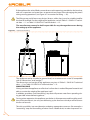
• The front of the appliance must be at least 80 cm away from walls or other fixed
constructions; the right and left sides must have a minimum clearance of 45 cm; the
minimum rear clearance from walls is 60 cm. (see Figure 4.2 Clearances → 30).
• No obstruction or overhanging structure (protruding roofs, eaves, balconies, ledges, trees) must obstruct either the air flowing from the top part of the appliance, or
the exhaust fumes outlet.
• The appliance must be installed in such a way that the exhaust fumes outlet is not
in the immediate vicinity of any external air inlets of a building. Respect current
regulations regarding the exhaust fumes outlet.
• Do not install the appliance close to flues, chimneys or other similar structures,
in order to prevent hot or polluted air from being drawn by the fan through the
condenser. In order to function correctly the appliance must use clean air from the
environment.
• If it is necessary to install the appliance near buildings, make sure that the appliance is not in the line of water dripping from guttering or similar.
• Fit a gas cock on the gas supply line.
• Fit antivibration joints on the hydraulic connections.
4.2POSITION OF THE APPLIANCE
Lifting the appliance and placing it in position
The appliance must be kept in the same packing in which it left the factory while it is
moved on site.
Packing must only be removed upon final installation.
27
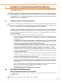
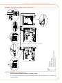
If the appliance has to be lifted, connect braces to the openings provided on the base bar,
and use suspension and spacer bars to prevent these braces from damaging the panels
during moving operations (see Figure 4.1 Instruction for lifting → 28).
The lifting crane and all accessory devices (braces, cables, bars) must be suitable sized for
the load to be lifted. For the weight of the appliance, consult Table 2.1 GAHP-A LT technical data → 11 or Table 2.2 GAHP-A HT technical data → 12.
The manufacturer cannot be held responsible for any damage that occurs during
the setting up of the appliance.
Figure 4.1 – Instruction for lifting
The appliance can be installed at ground level, on a terrace or on a roof (if compatible
with its “dimensions” and “weight”).
The dimensions and weight of the appliance are given in Table 2.1 GAHP-A LT technical
data → 11 or Table 2.2 GAHP-A HT technical data → 12.
MOUNTING BASE
Always position the appliance on a flat level surface that is made of fireproof material and
able to sustain the weight of the appliance itself.
In addition, provide a small “containing” step that will prevent water from spreading during possible winter defrosting phases.
During winter operation, the appliance, on the basis of temperature and humidity conditions of the outside air, can carry out defrosting cycles that cause the layer of frost/ice on
the fan coil to melt.
Take this possibility into consideration, adopting appropriate measures (for example: a
“containing” step and channelling of water into a suitable drain) in order to prevent “un28
Installation, user and maintenance manual – GAHP-A
controlled” spread of water around the appliance and the consequent risk that a layer of
ice will form (with the danger of falls on the part of passing people).
The manufacturer may not be held responsible for any damage arising from the
failure to observe this warning.
Installation at ground level
If a horizontal support base is unavailable (see also "SUPPORTS and LEVELLING" below), it
is necessary to create a flat level base in concrete which is larger than the dimensions of
the base of the appliance by at least 100-150 mm on each side.
The dimensions of the appliance are given in Table 2.1 GAHP-A LT technical data → 11 or
Table 2.2 GAHP-A HT technical data → 12.
Provide a “containing” step and a suitable drainage channel for the water.
Installation on a terrace or roof
Position the appliance on a levelled flat surface made of fireproof material (see also "SUPPORTS and LEVELLING" below).
The structure of the building will have to support the weight of the appliance added to
the weight of the supporting base.
The weight of the appliance is given in Table 2.1 GAHP-A LT technical data → 11 or Table
2.2 GAHP-A HT technical data → 12.
Create a “containing” step and a suitable drainage channel for the water, providing a
gangway around the appliance for maintenance purposes.
Although the appliance produces vibrations of limited intensity, the use of antivibration
mounts (available as accessories, see Section 7 ACCESSORIES → 67) is strongly recommended in such cases of installation on roofs or terraces in which resonance phenomena
may arise.
In addition, it is advisable to use flexible connections (anti-vibration joints) between the
appliance and the hydraulic and gas supply pipes.
Avoid positioning the appliance directly above rest areas or other areas that require
quiet.
SUPPORTS and LEVELLING
The appliance must be correctly levelled by placing a level on the upper part of the
appliance.
If necessary, level the appliance with metal spacers, placing them appropriately in relation to the mounts; do not use wooden spacers as these degrade quickly.
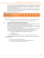
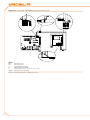
CLEARANCES
Position the appliance so as to maintain minimum clearances from combustible surfaces, walls or other appliances, as illustrated in Figure 4.2 Clearances → 30.
Minimum clearances are necessary in order to be able to carry out maintenance operations and to ensure the correct airflow required for heat exchange with the finned coil.
29
Figure 4.2 – Clearances
Position the appliance preferably out of range of rooms and/or environments where strict
silence is required, such as bedrooms, meeting rooms, etc.
Evaluate the acoustic impact of the appliance on the basis of the installation site: avoid
locating the appliance in positions (corners of buildings, etc.) that could amplify the noise
it produces (reverb effect).
4.3HYDRAULIC CONNECTIONS
General indications
• The hydraulic plant may be created using pipes in stainless steel, black steel, copper or crosslinked polyethylene for heating/cooling plants. All water pipes and pipe
connections must be adequately insulated in accordance with current regulations,
to prevent heat loss and the formation of condensate..
• To prevent icing in the primary circuit in the winter, the appliance is equipped with
an antifreeze device that activates the external water circulation pump of the primary circuit (if controlled by the appliance) and the burner of the appliance itself
(when necessary). It is therefore necessary to ensure a continuous supply of electricity and gas to the appliance throughout the whole of the winter period. If it is
not possible to ensure a continuous supply of electricity and gas to the appliance,
use glycol antifreeze of the inhibited monoethylene type.
• If glycol antifreeze is to be used (see Paragraph 4.6 FILLING OF HYDRAULIC CIRCUIT → 34), DO NOT USE galvanised pipes, as they are potentially subject to corrosion phenomena in the presence of glycol.
• When rigid pipes are used, to prevent the transmission of vibrations, it is recommended that the appliance water inlet and outlet are connected with antivibration
joints.
30
Installation, user and maintenance manual – GAHP-A
WARNING: the presence of free chlorine (CL2) in the water can damage steel or copper
parts of the installation. Make sure that water does not contain free chlorine; if in doubt,
it is recommended to make a specific analysis and/or add to water some specific product
(by example, Alphi-11 Protector, by Fernox, which also has inhibitory effect against possible icing). For further details, please contact directly Robur SpA (phone: 035 888 111).
The non-respect of the above recommendations can compromise the smooth operation
and the lifetime of the appliance, invalidating warranty.
Table 4.1 – Chemical and physical parameters of water
CHEMICAL AND PHYSICAL PARAMETERS OF WATER IN HEATING/COOLING SYSTEMS
PARAMETER
UNIT OF MEASUREMENT
pH
\
Chlorides
mg/L
Total chlorine
mg/L
Total hardness (CaCO3)
°F
Iron
mg/L
Copper
mg/L
Aluminium
mg/L
Langelier’s index
\
SUBSTANCES HAZARDOUS EVEN AT VERY LOW CONCENTRATION
Free chlorine
Fluorides
Sulphides
OPTIMAL VALUE
6,5 - 8,0
< 125
<5
10 - 15
< 50
<3
<3
0
ABSENT
ABSENT
ABSENT
Physical and chemical properties of the system water.
The components described below, are those to be always fitted in proximity to the
appliance:
• ANTIVIBRATION JOINTS in line with the water and gas connections of the
appliance.
• MANOMETERS installed in the inlet and outlet water pipes.
• INLET FLOW CALIBRATION VALVE, either of the gate valve or the overcentre valve
type, installed in the water inlet pipe of the appliance (only if the appliance is controller by a DDC).
• WATER FILTER installed in the appliance water inlet pipe.
• ISOLATION BALL VALVE in the water and gas pipes of the plant.
• 3 BAR SAFETY VALVE installed in the appliance outlet water pipe.
• PLANT EXPANSION TANK installed in the appliance outlet water pipe.
• EXPANSION TANK for individual appliance installed in the appliance water outlet
pipe (primary side). Provide a plant expansion tank in any case (secondary side),
installed in the appliance water outlet pipe.
The appliance is not equipped with an expansion tank: therefore it is necessary to install a
suitable expansion tank, sized in relation to the maximum heat excursion and maximum
operating pressure of the water of the plant.
•
•
•
v ariable rate WATER CIRCULATION PUMP, FOR PLANT WITH A SINGLE APPLIANCE,
located on the water inlet pipe of the appliance, flowing towards the appliance.
variable rate WATER CIRCULATION PUMP, FOR PLANT WITH A SEVERAL APPLIANCES
(each appliance have is pump), flowing towards the appliance.
PLANT FILLING SYSTEM: if automatic filling systems are used, a seasonal check of
the percentage of monoethylene glycol in the plant is recommended.
31
For the others components to instal on the system refer to "Design Manual" for the GAHP
line. For further information or technical support in this regard, contact Robur S.p.A.'s
Presales Office (tel.+39 035.888.111) or visite site www.robur.it.
The operations necessary for the First Activation or Regulation of the appliance must be
carried out exclusively by an authorised Robur Technical Assistance Centre (TAC). These
operations are described in Section 6 INITIAL ACTIVATION AND MAINTENANCE → 59.
The products' guarantee is void if initial activation is not carried out by a Robur TAC.
4.4GAS SUPPLY SYSTEM
The installation of gas supply pipes must be carried out in compliance with norms and
other current regulations.
The gas mains pressure must be in the range given in Table 6.1 Network gas
pressure → 61.
Supplying gas to the appliance at higher pressures than those indicated above can damage the gas valve, giving rise to a situation of danger.
For LPG systems fit a first stage pressure reducer of the flow necessary near the liquid gas
tank to reduce the pressure to 1.5 bar and a second stage pressure reducer from 1.5 to
0.03 bar near the appliance.
LPG may cause corrosion. The connectors between the pipes must be made of a material
that is resistant to this corrosive action.
Vertical gas pipes must be equipped with a siphon and provided with a drain for the con
densate that may form inside the pipe during cold periods. It may also be necessary to
insulate the gas pipe to prevent the formation of excessive condensate.
In any case, provide a cut-off valve (cock) on the gas supply line, to isolate the appliance
if required.
For data regarding hourly fuel consumption of the appliance, refer to Table 2.1 GAHP-A LT
technical data → 11 or Table 2.2 GAHP-A HT technical data → 12.
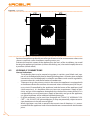
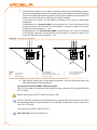
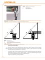
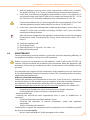
4.5CONDENSATE DISCHARGE CONNECTION
The fumes condensate outlet is on the left of the unit.
The unit is supplied complete with a siphon to which a piece of pipe is attached. During
transport, the pipe is stored inside the unit’s left mounting bracket at the front of the
appliance.
To install/connect the pipe, proceed as follows:
1. Pass the pipe through the hole in the left mounting bracket (see Figure 4.3 Position
of condensate discharge and manual reset fumes thermostat → 33).
2. Connect the tube to a plastic condensate discharge manifold of the correct
length.
3. The connection between the pipe and the condensate manifold must be in a visible location.
32
Installation, user and maintenance manual – GAHP-A
Figure 4.3 – Position of condensate discharge and manual reset fumes thermostat
LEGEND
ACondensate drain pipe
BCondensate drain siphon
CManual reset fumes thermostat
The condensate discharge to the sewer must be:
• sized so as to discharge the maximum condensation flow (see Table 2.1 GAHP-A LT
technical data → 11 or Table 2.2 GAHP-A HT technical data → 12 under the respective heading);
• implemented with material capable of resisting a degree of acidity equal to 3 - 5
pH;
• sized to ensure a slope of 10mm per metre of length; if this slope cannot be
achieved, a condensate pump (available as an accessory) must be installed near to
the discharge - see Section 7 ACCESSORIES → 67);
• implemented in such a way as to prevent the condensate icing in the expected
operating conditions;
• mixed, for example, with domestic effluent (washing machine, dishwasher, etc.),
usually of base pH, so as to form a buffer solution before discharge into the sewer.
Do not discharge the condensate into the guttering, since it may ice and corrode the
materials normally used for gutters.
LOADING THE SIPHON
Proceed as follows to load the siphon:
1. Connect the condensate discharge pipe to a drain.
2. Pour 0.2 litres of water directly into the fumes discharge pipe and check that the
siphon is full (detail B in Figure 4.3 Position of condensate discharge and manual
reset fumes thermostat → 33).
If the appliance is operated with the siphon empty, there is a risk of leaks of combusted
gas.
33
4.6FILLING OF HYDRAULIC CIRCUIT
After having completed all the connections of the hydraulic, electrical and gas supply
plants, the hydraulic system installation technician can proceed with filling the hydraulic
circuit, observing the following stages:
You will need: the appliance connected hydraulically and electrically.
1. A
ctivate the automatic air bleeding valves present in the plant and open all thermostatic valves.
2. Fill the hydraulic circuit, ensuring the minimum water content in the plant, and
adding, if necessary, to the plant water (free of impurities) a quantity of monoethylene glycol in proportion with the minimum winter temperature in the installation
zone (see table 4.2 Percentage of monoethylene glycol → 35).
3. Check the filter on the return pipe for impurities; clean it if necessary.
4. Check that the siphon on the drainage condenses has been filled with water as
indicated in the relative paragraph.
5. Bring the plant to the correct pressure, making sure that the water pressure is not
less than 1 bar and not over 2 bar, and run the circulation pump for at least 30 minutes. Check the water filter again and clean it if necessary.
To facilitate the operation of bleeding air from the hydraulic circuit, the appliance is
equipped with an additional manual air bleeding valve.
Possible use of glycol antifreeze
Glycols, normally used to lower the freezing point of water, are substances in an intermediate state of oxidisation which, in the presence of oxidising agents such as oxygen, are
transformed into corresponding acids. This transformation into acids increases the corrosive nature of the fluid contained in the circuit. For this reason, mixtures that are commercially available almost always contain inhibiting substances that are able to control the
pH of the solution. A necessary condition for the oxidisation of the glycol, and therefore
its degradation, is the presence of an oxidising agent such as oxygen. In closed circuits
in which no replenishment of water, and therefore of oxygen, occurs over the course of
time, once the oxygen initially present has reacted, the degenerative phenomenon of
glycol is hugely inhibited.
Most circuits, however, are of the non-sealed type, and therefore receive a more or less
continuous supply of oxygen.
Therefore it is essential, whatever type of glycol is in question, to verify that it is adequately inhibited and that the necessary checks are regularly performed during its entire
period of use.
Antifreeze liquids for cars, which do not contain inhibiting components other than ethylene glycol, are not recommended for cooling and heating plants.
The manufacturer does not accept any contractual or extra-contractual liability for
damage caused by the use or incorrect disposal of glycol antifreeze.
It is equally important to recall that the use of monoethylene glycol modifies the thermophysical characteristics of the water in the plant, and in particular its density, viscosity
and specific average heat. Always check the date of expiry and/or degradation of the
product with the supplier.
In the Table 4.2 Percentage of monoethylene glycol → 35 is shown the approximate
freezing temperature of the water and the consequent increased drop in pressure of the
appliance and of the circuit of the plant, according to the percentage of monoethylene
glycol.
34
Installation, user and maintenance manual – GAHP-A
This Table 4.2 Percentage of monoethylene glycol → 35 should be taken into account
for the sizing of the pipes and the circulation pump (for calculation of internal pressure
drops of the appliance, refer to the Table 2.1 GAHP-A LT technical data → 11 or Table 2.2
GAHP-A HT technical data → 12).
Nevertheless, it is advisable to consult the technical specifications of the monoethylene
glycol used. If automatic loading systems are used, a seasonal check of the quantity of
glycol present in the plant is also necessary.
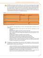
Table 4.2 – Percentage of monoethylene glycol
% of MONOETHYLENE GLYCOL
WATER FREEZING POINT TEMPERATURE
PERCENTAGE OF INCREASE IN PRESSURE DROPS
LOSS OF EFFICIENCY OF UNIT
10
-3°C
---
15
-5°C
6%
0,5%
20
-8°C
8%
1%
25
-12°C
10%
2%
30
-15°C
12%
2,5%
35
-20°C
14%
3%
40
-25°C
16%
4%
Technical data for filling the hydraulic circuit
If the percentage of glycol is ≥ 30% (for ethylene glycol) or ≥ 20% (for propylene glycol):
•
then parameter 182 in menu 4 must be set to “1” (at the installer’s care).
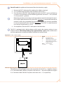
4.7EXHAUSTING THE COMBUSTION PRODUCTS
The appliance is approved for the connection of the combustion product exhaust pipes,
present on each single unit, to a flue linked directly to the outside.
Each single unit is provided with a connection of Ø 80 mm (equipped with a suitable
seal) located on the left side (see Figure 2.1 Size (Standard ventilation) → 14 or Figure 2.2
Size → 15) and outlet in a vertical position.
Each unit of the appliance is supplied complete with an exhaust air duct installation kit,
to be fitted to the appliance by the hydraulic system installation technician.
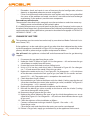
The exhaust air duct installation kit consists of (see Figure 4.4 Fume outlet → 36):
• n. 1 exhaust air pipe Ø 80mm (length 300 mm) with terminal;
• n. 1 rain cover;
• n. 1 curve 90° Ø 80 mm.
To assemble and fit the external exhaust fumes installation kit, proceed as follows:
You will need: the appliance positioned in its installation site (refer to Figure 4.4 Fume
outlet → 36).
1. F it the rain cover (C) on the curve 90° (A).
2. Fit the curve 90° (A) to the clamp on the left side of the appliance.
3. Fit the terminal/pipe assembly (B) to the curve (A).
35
Figure 4.4 – Fume outlet
LEGEND
ACurve 90° Ø 80
BPipe Ø 80 Lg.300 mm w/terminal
Crain cover
4.8PROGRAMMING OF HYDRAULIC PARAMETERS
The operations described in this paragraph are necessary only if the appliance is not connected to a DDC or to a CCP.
If the appliance is connected to a DDC, follow the instructions given in the DDC manuals
exclusively.
This paragraph explains how to set the hydraulic parameters on the electronic board
of the appliance. Users not familiar with the basic procedures for the use of the board
should refer to Paragraph 3.2 ON-BOARD ELECTRONICS → 19.
To configure the appliance, access menu 3 of the electronic board.
With regard to the hydraulic configuration, six parameters may be set: select the letter E
to exit to the previous menu.
Table 4.3 – Menu 3 parameters
HYDRAULIC PARAMETER
Hot water thermostat control selection
Hot water setpoint
Hot water temperature differential
(EXIT MENU)
THE DISPLAY SHOWS
3.160
3.161
3.162
3. E
Description of parameters:
• Select water thermostating, parameter 160: this parameter may have two values, 0
or 1. When the user chooses:
·0: the temperature that affects the activation and deactivation of the appliance is detected by the sensor on the INLET water, i.e. water flowing into the appliance.
·1: the temperature that affects the activation and deactivation of the appliance is detected by the sensor on the OUTLET water, i.e. water flowing out of the appliance.
36
Installation, user and maintenance manual – GAHP-A
•
ater set-point, parameter 161: this parameter sets the water temperature that,
W
when reached, causes the appliance to be deactivated (when the power modulation is not active - parameter 181)
• Water differential, parameter 162: this parameter represents an interval in degrees
that, when added to the set-point, defines the temperature at which the appliance
is reactivated. This parameter is used only if the power modulation is NOT active
(parameter 181).
The appliance functions by heating the water until it reaches the set-point temperature.
At this point, if the power modulation is not active (parameter 181), it switches off. The
temperature of the water goes down again until it reaches the temperature corresponding to "set-point + differential"; when this is reached the appliance switches on again.
Example:
Thermostating: reading from inlet sensor.
Parameter 181: 0 (power modulation NOT active)
Set-point: +40.0°C
Differential: - 2.0° C
• The appliance is functioning: the water in the plant heats up until it reaches the
set-point temperature = +40°C.
• The appliance switches off: the water in the plant, returning from use, becomes
progressively cooler, until it reaches a temperature of 38°C = 40°C - 2°.
• The appliance switches on again, and the plant water heats up again.
• The cycle is repeated.
The following procedure illustrates in detail how to configure the parameters on the electronic board inside the appliance.
If the procedures for how to access the knob and menus are not familiar, see paragraphs
"Display and knob" and "How to access the menus" and following.
To set the parameters of menu 3:
You will need: the appliance on and access to the electrical panel, see "Display and
knob".
Access menu 3. The display shows the first parameter of the menu, number 160.
1. Turn the knob clockwise to scroll through the parameters: 3.160, 3.161, 3.162; lastly
the letter E is shown.
2. Press the knob when a parameter is displayed to select it, or when E is displayed to
exit the menu.
3. For example, to set parameter 161 (hot water set-point), proceed as follows:
· Select the parameter: turn the knob until the display shows 3.161;
· Press the knob to access the value of the parameter; the display shows the previously set value, which flashes, for example 40.0 °C;
· Turn the knob to modify the value of the parameter;
· Press the knob to confirm the value selected; the display shows the current parameter again, 3.161. The new value for this parameter has been set.
4. If other parameters are to be modified, proceed as described previously, and then
exit from the menu by pressing the knob on the letter E.
To exit the menu, turn the knob clockwise until E is displayed, then press it to confirm. For
details regarding the codes displayed by the appliance during operation, see Paragraph
8.1 MACHINE OPERATING CODES → 69.
37
38
Installation, user and maintenance manual – GAHP-A
5ELECTRICAL SYSTEM INSTALLATION TECHNICIAN
This section illustrates the operations to perform for the correct electrical installation of
the appliance, and contains electrical diagrams that may be of use in the event of maintenance operations.
Installation of the appliance may only be carried out by firms that are qualified in accordance with current legislation in the country of installation, i.e. by professionally qualified
personnel.
Installation that is incorrect or that does not comply with current legislation may cause
damage to people, animals or things; Robur S.p.A. is not responsible for any damage
caused by installation that is incorrect or that does not comply with current legislation.
Figure 5.1 Electronic board S61 → 39 and Table 5.1 Electronic board S61 → 40 detail the
S61 controller’s inputs and outputs. The supplementary controller Mod10 is shown in
detail in Figure 5.2 Mod10 controller → 41.
The appliance and the system can be controlled and regulated in one of the following
ways depending on the type of installation and control system selected:
• TYPE
A (NOT APPLICABLE at PRO Platform): controlled by Comfort Control
Panel.
• TYPE
B: controlled by DDC (see Figure 5.3 Direct Digital Control (DDC) → 41).
• TYPE
C: controlled by consent switch (e.g. on-off switch, ambient thermostat, timer, etc.).
In Paragraph 5.1 ELECTRICAL DIAGRAMS OF THE APPLIANCE → 42 may be found the
Electrical diagrams of the appliance.
Figure 5.1 – Electronic board S61
LEGEND
See table below
SCH S61
39
Table 5.1 – Electronic board S61
CODE
SCH1
SCH3
A1, A2
ENC
F1
F2
F3
F4
FAN (BK, WH, BR)
FL
FS5 (24V AC)
IGN.BOX (L, N)
J1
J10
J82
JP10
JP12
JTAG
MAIN 230V (L, N)
N.O. contact
P7 (R, W, Y, o)
P8 (GND, L, H)
PUMP 230V (L, N)
SPI
SRT1
SRT2
TA
TA1
TA2
TCN
TF
TG
THMF
THRF
TL
SCH S61
40
DESCRIPTION
Electronic board S61
Mod10 electronic controller (see figure for further details)
Auxiliary inputs
Knob
Fuse T 2A
Fuse F 10A
Fuse T 2A
Fuse T 3.15A
Fan output
water flow switch input (GAHP-A)
Controller power 24-0-24 Vac
Flame controller power 230 V AC
CAN BUS jumper
Jumper N.O. contact
W10 board connector (on Mod10)
6-pole flame controller connector
Exhausted gas probe input
S61 controller programming connector
S61 controller power 230 V AC
Pump contact, N.O.
Consent inputs
CAN BUS connector
Hydraulic pump power output
Communication port with Mod10 controller
Hydraulic pump rotation sensor input
Hot water flowmeter input [E3 A/GS/WS]
Ambient temperature probe input
Input probe of evaporator output
Not used
Combustive air temperature probe input
Exhausted gas thermostat input
Generator temperature probe input
Hot water delivery temperature probe input
Hot water return temperature probe input
Generator limit thermostat input
Installation, user and maintenance manual – GAHP-A
Figure 5.2 – Mod10 controller
LEGEND
HFLOWNot used
CFLOWNot used
J51SPI connector
HPMPPrimary circuit hot water pump control
output (0-10 V) [E3 A/GS/WS]
CPMPCold side water pump control output
[E3 GS/WS]
NC1-C1Status indication of locking warnig/error
CN5Blower control
J82W10 auxiliary controller connector
J83W10 cable shielding connection W10
CN1Inputs 0-10V (not used)
Mod10 controller
Figure 5.3 – Direct Digital Control (DDC)
LEGEND
DDCDirect Digital Control
41
LEGEND
SCH1S61 controller
SCH2W10 controller
SCH3Mod10 controller
TERPower terminal block
CNTBOXFlame controller
PWRTRController transformer
BLWBlower
PMPHydraulic pump
IGNTRIgnition transformer
IGNIgnition electrodes
FLSFlame sensor
LSGas valve ON indicator lamp
GVGas solenoid valve
TCManual fumes thermostat
TLGenerator limit thermostat
FMFlowmeter (only for E3-A)
FLFlowmeter (only for GAHP-A)
CWSCondensation water sensor
VDDefrosting valve
TMThermostat for electromagnet
FANFan
CFan capacitor
(not in the low-noise unit)
EMElectromagnet
TSWinter kit thermostat
RScondensation siphon resistance
FScondensation pipe resistance
RGGas valve resistance
THRCHot water delivery temperature probe
THMCHot water return temperature probe
TMIXCombustive air temperature probe
TAAmbient temperature probe
TGGenerator temperature probe
PT1000Exhausted gas probe
TEVAEvaporator outlet probe
REEDHydraulic pump rotation sensor
5.1ELECTRICAL DIAGRAMS OF THE APPLIANCE
Figure 5.4 – Appliance internal wiring diagram
42
Installation, user and maintenance manual – GAHP-A
5.2HOW TO CONNECT THE APPLIANCE ELECTRICALLY
Before making the electrical connections, make sure that work is not carried out on live
elements.
You will need: the appliance in its permanent location.
1. P
repare a cable of the FG7(O)R 3Gx1.5 type for the power supply to the appliance.
2. Connect the appliance to the mains (with the cable indicated in point 1), fitting in
proximity to the mains a general external bipolar circuit breaker (see detail «GS» in
Figure 5.5 Electrical wiring diagram → 43) with 2 type T 5A fuses or a 10 A magnetothermic switch.
3. Make the electrical connection in such a way that the ground wire is longer than
the live wires. In this way it will be the last wire to be pulled away if the mains cable
should accidentally be pulled, and will thus guarantee the ground connection.
The electrical safety of the appliance is guaranteed only when it is correctly connected
to an efficient grounding system, executed in accordance with current safety regulations.
Do not use gas pipes to ground electrical appliances.
Figure 5.5 – Electrical wiring diagram
LEGEND
TERterminal board
Lphase
Nneutral
Components NOT SUPPLIED
GSgeneral switch
Example of connection of appliance to 230 V 1 N - 50 Hz electricity supply
5.3TYPE B (DDC)
This paragraph illustrates the operations to be performed when one or more appliances
are connected to a Direct Digital Controller (DDC). In particular:
1.
2.
3.
4.
5.
hat is the CAN bus cable.
W
How to connect the CAN BUS cable to the appliance's controller
How to connect the CAN BUS cable to the DDC.
How to connect the DDC.
How to connect the plant water circulation pump.
For specific information regarding the DDC, refer to the specific manuals supplied with
it.
The appliance and the DDC communicate with each other via a CAN bus network.
The CAN bus network is characterized by a series of elements (appliances or DDCs) called
nodes, connected to each other by a three-wire cable. The nodes are of two types: terminal nodes and intermediate nodes.
43
•
T erminal nodes are appliances or DDCs that are connected to one other element
only.
• Intermediate nodes are appliances or DDCs that are connected to two other
elements.
The diagram in Figure 5.6 Example of CAN BUS → 44 gives an example of a CAN BUS
network: 3 appliances are connected to each other and to 1 DDC. Appliance D and the
DDC (A) are terminal nodes, while appliances C and B are intermediate nodes as they are
connected to 2 elements.
It is possible to place one DDC at any point of the CAN bus network: appliances and DDCs
may act equally as terminal or intermediate nodes. One DDC can control and monitor up
to 16 appliances. If there are more than 16 appliances on the network, it is necessary to
connect more than one DDC on the same network, up to a maximum of 3.
Figure 5.6 – Example of CAN BUS
LEGEND
ACCP or DDC
B-C-DAppliance
1-4Terminal nodes
2-3Intermediate nodes
Terminal nodes and intermediate nodes
What is the CAN bus cable
The CAN bus cable must meet the {Honeywell SDS standard}.
Table 5.2 CAN BUS cables type → 44 gives details of some types of CAN bus cable, grouped
according to the maximum distance covered by each single type.
Table 5.2 – CAN BUS cables type
CABLE NAME
Robur
ROBUR NETBUS
Honeywell SDS 1620
BELDEN 3086A
TURCK type 530
DeviceNet Mid Cable
TURCK type 5711
Honeywell SDS 2022
TURCK type 531
SIGNAL / COLOR
MAX LENGTH
H= BLACK
L= WHITE
GND= BROWN
450 m
H= BLACK
L= WHITE
GND= BROWN
450 m
H= BLUE
L= WHITE
GND= BLACK
450 m
H= BLACK
L= WHITE
GND= BROWN
200 m
Note
Ordering Code O-CVO008
In all cases the fourth
conductor should not be
used
Example types of cables used to connect the CAN network.
For overall distances to cover of ≤200 m and networks with a maximum of 6 nodes (a
typical example: up to 5 GAHP-A + 1 DDC) a simple shielded cable 3x0.75 mm may be
used.
44
Installation, user and maintenance manual – GAHP-A
As shown in Table 5.2 CAN BUS cables type → 44, the CAN connection requires a CAN bus
cable with 3 wires. If the available cable has more than 3 coloured wires, use the wires
with the colours indicated in 5.2 CAN BUS cables type → 44 and cut the remaining ones.
The ROBUR NETBUS cable is available as an accessory, see Section 7 ACCESSORIES → 67.
How to connect the CAN BUS cable to the appliance's controller
The CAN BUS cable must be connected to the special socket on the machine’s on-board
controller, as shown below (see Figure 5.7 CAN BUS cable connection → 45).
Figure 5.7 – CAN BUS cable connection
LEGEND
AInsulating tape to protect board/shield
BCAN bus cable shield
CCable fixing bracket
DConnector for connecting terminals of
CAN bus wires
ETerminals (n° 3) of CAN bus cable
Example of a single CAN bus cable connected to the board
Before working on the electrical panel of the appliance, make sure that it is not connected to the power supply.
1. C
ut a length of cable, long enough to allow it to be installed without kinking.
2. Having chosen one end of the length of cable, remove the sheath from a length of
approximately 70-80 mm, taking care not to cut the shielding (metallic shield and/
or aluminium sheet and, if present, the bare connector in contact with the shield)
and the wires contained within.
3. If the cable is too thin to be held in place in the cable holder bracket (detail C in
Figure 5.7 CAN BUS cable connection → 45), make it thicker by wrapping insulating tape around it on the sheath in the area adjacent to the stripped part (to an
approximate diameter of 12-13 mm).
4. Pull back the shielding in the sheathe; apply electrician’s tape to the end of the
shielding as pulled back (detail A, Figure 5.7 CAN BUS cable connection → 45).
5. If the appliance is a terminal node of the network connect the three coloured
wires to the orange connector, as shown in detail "A" of Figure 5.8 Electrical wiring diagram → 46. Respect the correct indications L, H, GND provided in Table 5.2
CAN BUS cables type → 44, on the figure and on the diagram at the base of the
connector.
6. If the appliance is an intermediate node repeat the operations from step 2 to step
5 for the other length of cable required (so to will have two cable lengths everyone
without the sheath). To interlace between they the threads with the same color
and to connect them to the orange connector, as shown in detail "B" of Figure 5.8
Electrical wiring diagram → 46.
45
7. F ix the CAN bus cable (or two cables, according to the type of node being connected) to the cable fixing bracket in the upper part of the inside of the electrical panel
so that the rolled-back sheathing makes solid contact with the metal bracket. The
cables must be held firmly in place by the bracket if pulled.
To position the jumpers on the board according to the type of node being
configured:
• If the appliance is a terminal node on the network (i.e. 3 wires are inserted in the
orange connector on the board): set the jumpers as shown in detail "A" of Figure
5.8 Electrical wiring diagram → 46:
• If the appliance is an intermediate node on the network (i.e. 6 wires are inserted
in the orange connector on the board); set the jumpers as shown in detail "B" of
Figure 5.8 Electrical wiring diagram → 46:
Figure 5.8 – Electrical wiring diagram
LEGEND
SCHelectronic board
GNDCommon data
LData signal LOW
HData signal HIGH
J1Jumper CAN-BUS in board
ADetail case "terminal node" (3 wires;
J1=jumper "closed")
BDetail case "intermediate node" (6
wires; J1=jumper "open")
P8Port can/connector
Connection cable CAN BUS to electronic board: detail A case "terminal node", detail B case "intermediate node"
8. A
fter having carried out all the above operations, close the electrical panel and
refit the front panel of the appliance.
How to connect the CAN BUS cable to the DDC
The CAN bus cable is connected to the specific orange connector (P8) supplied with the
DDC in a bag.
Before working on the DDC, make sure that it is off.
The DDC, like the controller on the appliance, has jumpers that must be moved so that it
can be configured as an intermediate or terminal node. The position of the jumpers on a
new DDC is CLOSED.
To connect the CAN bus cable to a DDC:
You will need: DDC not powered up.
46
Installation, user and maintenance manual – GAHP-A
1. D
epending on the type of node being configured, set the DDC's jumpers J21 as
shown in detail "A" or detail "B" in Figure 5.10 detail wires and jumpers J21 - terminal/intermediate node DDC → 48. If necessary, open the DDC's back panel (4
screws); after jumpers J21 have been correctly positioned, close the cover again
and retighten the 4 screws.
• If the DDC is an intermediate node on the network (with no. 6 wires in the orange
connector "P8"): set the jumpers "J21" as shown in detail "B" of Figure 5.10 detail
wires and jumpers J21 - terminal/intermediate node DDC → 48: Jumpers OPEN.
• If the DDC is an terminal node on the network (with no. 3 wires in the orange connector "P8"): set the jumpers "J21" as shown in detail "A" of Figure 5.10 detail wires
and jumpers J21 - terminal/intermediate node DDC → 48: Jumpers CLOSED.
2. Prepare the orange CAN bus connector, from the supplied sleeve.
3. Cut a length of cable, long enough to allow it to be installed without kinking.
4. Remove the sheath for a length of approximately 70-80 mm, taking care not to cut
the shielding (metallic shield and/or aluminium sheet and, if present, the bare connector in contact with the shield) and wires contained inside.
5. Roll the shielding and connect it to a 4-mm eyelet terminal, as illustrated in Figure
5.9 Connection from CAN BUS to connector P8 → 48, details C and D. Now proceed
as follows:
6. If the DDC is an terminal node connect the three coloured wires to the orange
connector "P8", following the diagram provided in detail "A" of Figure 5.10 detail
wires and jumpers J21 - terminal/intermediate node DDC → 48. Observe the terminal markings L, H, GND (on the DDC at the base of the socket "P8") which are given
both in Table 5.2 CAN BUS cables type → 44 and in the example.
7. If the DDC is an intermediate node repeat the operations from step 2 to step 4 for
the other length of CAN bus cable required. Connect the six coloured wires to the
orange connector "P8", following the diagram provided in detail "B" of Figure 5.10
detail wires and jumpers J21 - terminal/intermediate node DDC → 48. Observe the
terminal markings L, H, GND (on the DDC at the base of the socket "P8") which are
given both in Table 5.2 CAN BUS cables type → 44 and in the example.
8. Insert the orange connector ("P8") with the wires first into the opening prepared in
the cover of the DDC, and then into the appropriate socket on the DDC itself, making sure it is correctly inserted.
9. Use the rear cover bolts located near the CAN BUS socket to secure the 4 mm eyelet
(or 2 eyelets) (detail D, Figure 5.9 Connection from CAN BUS to connector P8 → 48).
The cable should be secured against pulling out.
47
Figure 5.9 – Connection from CAN BUS to connector P8
LEGEND
AInsulating tape to protect board/shield
BCAN BUS cable wires
CCAN bus cable shield
Dterminal and screw for fixing
Connection detail of cable CAN BUS.
Figure 5.10 – detail wires and jumpers J21 - terminal/intermediate node DDC
LEGEND
DDCDirect Digital Control
J21Jumper CAN-BUS in DDC board
Adetail case "terminal node" (3 wires; J21=jumper "closed")
Bdetail case "intermediate node" (6 wires; J21=jumper "open")
H,L,GNDdata signal wires
Detail terminal and intermediate node: jumpers position J21: "closed" - "open".
How to connect the DDC
The DDC requires a low voltage power supply (24 V) with a 230/24 V AC, 50 Hz safety
transformer; the minimum power requirement is 20 VA. For the connection use a cable
with the minimum specifications 2 x 0.75 mm2.
Connect the DDC to the transformer via the 4-pole connector provide for this, following
the diagram in Figure 5.11 DDC - electric supply → 49. Pass the cable through the opening in the cover before fixing the wires to the connector.
To power up the DDC, proceed as follows.
48
Installation, user and maintenance manual – GAHP-A
You will need: the appliance disconnected from the electricity supply
1. R
emove the DDC's back panel by undoing the 4 bolts securing it.
2. Cut a suitable length of power cord (minimum 2x0.75 mm2).
3. Pass the power cord (DDC side) through the hole in the DDC's cover and hook up
as shown in the example, with the following polarities: terminal 1 = 24 V; terminal
2 = 0 V; terminal 3 = ground.
Make the grounding connection on the transformer terminal connected to terminal 2 of the 4-pole connector (EP) of the DDC. Terminal 2 is connected internally to
terminal 3, and is thus grounded; if the transformer already has one wire grounded,
it must be connected to this terminal. Terminal 3 of the DDC’s 4 pole connector
must always be grounded (r ≤ 0.1Ω).
4. On completion, close the DDC's back panel with the 4 bolts.
The DDC is equipped with a backup battery which retains the memory settings in case
of power failure. The backup battery lasts approximately 7 years, after which time it
must be replaced by an authorised Robur Technical Assistance Centre.
Figure 5.11 – DDC - electric supply
LEGEND
DDCDirect Digital Control
ALsupply 4 poles connector
1clamp and wire for 24 Vac supply
2clamp and wire for 0 Vac supply
3clamp and wire for ground contact
(required connection)
DDCTRsafety transformer
- (230/24 Vac50/60 Hz)
DDC electric supply from external transformer
The following wiring diagrams show the connection of the DDC to 1 appliance (Figure
5.12 Connexion câble CAN BUS for plants with one unit → 50) and 2 appliances (Figure
5.13 Connexion câble CAN BUS for plants with more unit → 51) respectively.
49
Figure 5.12 – Connexion câble CAN BUS for plants with one unit
LEGEND
DDCdirect digital control
SCHelectronic board S61
J1Jumper CAN-BUS in board S61
J21Jumper CAN-BUS in board DDC
Aterminal nodes connection - (3 wires; J1 e J21 = "closed")
H,L,GNDdata signal wires (rif. cables table)
Connexion câble CAN BUS between one DDC and one unit
50
Installation, user and maintenance manual – GAHP-A
LEGEND
DDCdirect digital control
SCHelectronic board S61
J1Jumper CAN-BUS in board S61
J21Jumper CAN-BUS in board DDC
Aterminal nodes connection - (3 wires; J1 e J21 = "closed")
Bintermediate node connection - (6 wires; J1="closed")
H,L,Gnddata signal wires (rif. cables table)
Figure 5.13 – Connexion câble CAN BUS for plants with more unit
Connexion câble CAN BUS between one DDC and more unit
How to connect the plant water circulation pump
It is possible to control the pump of the plant either from the appliance's controller or
independently.
51
Controlling the pump from the appliance's controller
Control of the plant water circulation pump from the appliance's controller depends on
the power rating of the pump itself. 2 cases may be distinguished:
• Direct control from the controller with power absorbed by the pump less than 700
W. If the power absorbed by the pump is less than 700 W, make the connection as
shown in Figure 5.14 Electrical wiring diagram → 52 and check that the jumper
(J10, located at the bottom left of the controller, above the "NO Contact" contacts)
is CLOSED, as shown in detail A.
• Direct control from the controller with power absorbed by the pump of more than
700 W. If the power absorbed by the pump is more than or equal to 700 W, make
the connection as shown in Figure 5.15 Electrical wiring diagram → 53 using a con
trol relay. In this case it is necessary to OPEN the jumper (J10, located at the bottom
left of the controller, above the "NO Contact" contacts) positioning it as shown in
detail A of the Figure.
Figure 5.14 – Electrical wiring diagram
LEGEND
SCHelectronic board
TERterminal board
J10jumper closed
N.O. CONTACTclean exit normally open
Lphase
Nneutral
Components NOT SUPPLIED
CSON/OFF control switch
PMPwater pump <700W
GSgeneral switch
Example of pump/appliance electrical connection with 230 Vac pump (with absorbed power of < 700 W), controlled directly by the appliance.
52
Installation, user and maintenance manual – GAHP-A
Figure 5.15 – Electrical wiring diagram
LEGEND
SCHelectronic board
TERterminal board
J10jumper open
N.O. CONTACTclean exit normally open
Lphase
Nneutral
Component NOT SUPPLIED
CSON/OFF control switch
PMPwater pump =700W
KPcontrol pump relay
GSgeneral switch
Example of pump/appliance electrical connection with 230 Vac pump (with absorbed power equal or more than 700 W), controlled directly by the
appliance through a relay
If several appliances are connected on the same hydraulic circuit, it is always necessary
to provide a safety transformer (secondary SELV) and a respective control relay; make the
connections according to the diagram in Figure 5.16 Electrical wiring diagram → 54.
53
LEGEND
SCHelectronic board
J10jumper open
N.O. CONTACTclean exit normally open
Lphase
Nneutral
Components NOT SUPPLIED
PMPwater pump
KPcontrol pump relay
GSgeneral switch
PTRsafety transformer SELV
IPbipolar pump switch
Figure 5.16 – Electrical wiring diagram
Example of pump/appliance electrical connection with 230 Vac pump, controlled directly by the appliance through a relay and a SELV safety
transformer
Independent control of the pumps
If it is intended to manage the operation of the plant water circulation pump separately,
it is necessary to provide a delayed relay, with a de-excitation time of 10 minutes: after
54
Installation, user and maintenance manual – GAHP-A
the opening of the appliance's consent switch contacts, the circulation pump will thus
continue to circulate the water in the plant for a further 10 minutes, thereby ensuring the
complete dispersal of the heating energy produced.
When the pump is controlled by the appliance's controller, this delay is automatically applied by the board.
5.4TYPE C (Consent switch)
In this type of installation and control, the system pump does not vary the flow rate.
Before making the electrical connections, make sure that work is not carried out on live
elements.
General indications
• Check that the power supply voltage is 230 V 1N - 50 Hz power.
• Make the electrical connections as given in the following wiring diagrams.
• Make the electrical connection in such a way that the ground wire is longer than
the live wires. In this way it will be the last wire to be pulled away if the mains cable
should accidentally be pulled, and will thus guarantee the ground connection.
The electrical safety of the appliance is guaranteed only when it is correctly connected
to an efficient grounding system, executed in accordance with current safety regulations.
Do not use gas pipes to ground electrical appliances.
How to connect the consent switch
You will need: the appliance is not powered electrically (external master power switch
set to OFF)
1. C
onnect the consent switch (on-off switch or ambient thermostat or timer, etc.) to
terminals R and W on the appliance’s control circuit as shown in Figure 5.17 Electrical wiring diagram → 55 (detail “CS”).
For the appliance to operate correctly, it is ALWAYS necessary to provide a consent switch.
Do not use the general mains external circuit breaker («GS») to switch the appliance on
or off.
Figure 5.17 – Electrical wiring diagram
LEGEND
SCHElectronic board
RCommon
WTerminal consensus warming
Components NOT SUPPLIED
CSON/OFF command switch
electrical connections of ON/OFF command switch
55
How to connect the plant water circulation pump
For how to connect the system pumps, see the section with this title in Paragraph 5.3
TYPE B (DDC) → 43.
5.5HOW TO REMOTELY CONTROL THE FLAME CONTROLLER RESET
The flame controller reset can be controlled remotely by installing a button (not supplied) to the flame controller inside the unit’s electrical panel.
Connect the button as instructed below.
You will need: the appliance disconnected from the electricity supply
1. T he cable required to connect the reset button must be 3x0.75mm2.
2. Cut a suitable length of cable.
3. Connect the cable to the blind terminals A (see Figure 5.18 Button connection for
flame controller reset → 57).
The cable may not be longer than 20 metres.
Incorrect wiring of the reset button may damage the component irreparably. Check the
cabling carefully before powering the unit.
56
LEGEND
1White
2Grey
3Orange
4Green
5Yellow/Black
6Black
7Yellow/Green (Ground)
8Brown
9Blue
10Red
11Violette
12Pink
PLSReset button
ABlind terminals
Installation, user and maintenance manual – GAHP-A
Figure 5.18 – Button connection for flame controller reset
57
58
Installation, user and maintenance manual – GAHP-A
6INITIAL ACTIVATION AND MAINTENANCE
In this section you will find the following information:
• Indications required by the authorized Robur Technical Assistance Centre (TAC) in
order to carry out the entire procedure of first start-up of the appliance.
• Indications regarding maintenance operations of the appliance.
At the end of the section you will find instructions for changing the type of gas.
Before proceeding with the operations described in this section, the installation technician concerned is invited to read Paragraph 2.1 WARNINGS → 7. in regard to switching
the appliance on and off, refer to Paragraph 3.1 START UP (AND SHUT DOWN) → 17.
If the appliance is connected to a DDC (and the DDC is in controller mode), for the phases
of activation and deactivation of the appliance it is necessary to refer to the two manuals
dedicated to the DDC itself.
6.1PROCEDURE FOR INITIAL ACTIVATION
The entire procedure for the initial activation of the appliance must only carried out by
an authorised Robur Technical Assistance Centre (TAC). The product's guarantee may be
void if the procedure is not carried out by a Robur TAC.
On leaving the factory, the appliance is reliable and tested.
The entire procedure for initial activation of the appliance consists in carrying out the following (main) operating stages:
1. preliminary verification of plant compliance;
2. checking and adjusting the combustion parameters;
3. regulating the plant operating parameters.
Preliminary verification of plant compliance
The Robur TAC technician must:
• check that the whole plant has been manufactured in accordance with its design,
following the instructions supplied by the manufacturer and respecting current
legislation. The design must have been drawn up by a qualified self-employed professional person.
• check personally that all of the connections (hydraulic/gas and electrical) of the
appliance have been made correctly;
• Check that the necessary conditions for plant compliance effectively exist (as per
the declaration consigned to the user by the qualified firm that has carried out
installation of the appliance).
The Declaration of Compliance CERTIFIES that the plant conforms to current regulations.
This declaration is a compulsory document, and as such must be issued by law to the
owner by the qualified firm that has overseen the installation of the appliance.
• Check that the water pressure and flow in the hydraulic circuit and the dynamic
gas mains pressure are correct, as indicated by the manufacturer.
• Check that the electrical power supply is 230V 50Hz
• Check that the air/fumes pipes are properly connected.
• Check that the fumes condensate discharge is installed.
• Check that the safety clearances have been observed, as shown in Figure 4.2
Clearances → 30.
If all the conditions listed above exist, the TAC can proceed with the initial activation of
the appliance.
If any non-compliant elements arise during the initial verification, the TAC may choose
not to proceed with the operation of "initial activation".
59
In this case, the Robur TAC technician must:
• Advise the user/installation technician of any installation anomaly.
• Inform the user/installation technician of any situation that is deemed to be hazardous for the appliance and for people.
• Inform of any missing documentation relative to the plant.
• Indicate, in relation to the reports made, any corrective measures to be taken on
the plant which the installation technician will have to carry out in order to proceed with the operation of "initial activation".
It is the responsibility of the user/installation technician to carry out any corrective measures on the plant indicated by the TAC. Following such corrective measures performed
by the installation technician, the TAC will assess the plant again. At this point, if, in the
opinion of the TAC, safety and compliance conditions exist, the TAC must carry out the
"initial activation".
Plant situations that are hazardous for people and for the appliance.
If one of the following hazardous situations arises, the TAC must not carry out the "initial
activation":
• appliance installed indoors;
• appliance installed too near combustible surfaces or in any case in conditions that
do not permit access and maintenance operations in safety;
• control of switching on and off of the appliance not via the CCP/DDC or consent
switch but via the master power switch;
• situations attributable to defects or failures of the appliance that took place during
its transport or installation;
• smell of gas due to probable leaks from the plant itself and in any case all situations
that are due to non-compliant plants, considered potentially hazardous.
Anomalous plant situations.
If one of the following situations exists, the TAC may carry out the "initial activation" at its
discretion, but the appliance will be left off until conditions dictated by the manufacturer
are restored:
• installations (potentially not hazardous) not carried out according to good workmanship practices, installations (potentially not hazardous) not complying with
current national and local regulations;
• installations (potentially not hazardous) not carried out according to good
workmanship practices, not complying with the instructions supplied by the
manufacturer;
• installations that can lead to operating anomalies of the appliance.
Checking and adjusting the combustion parameters
During the initial activation procedure, the combustion parameters must be checked and
set ONLY by a Robur TAC. In this stage, NEITHER the user NOR the installation technician
is authorised to perform such operations, and in so doing may invalidate the guarantee
of the appliance.
The appliance is supplied with all of its units already regulated for the type of gas for
which the appliance itself is set up.
The type of gas for which the appliance is set up can be identified from the adhesive label
located on the unit's internal gas pipe (see detail M, Figure 6.2 Gas changeover → 65).
The appliance is supplied with the nozzles required to make the gas type change to G30
and G31.
60
Installation, user and maintenance manual – GAHP-A
During the first start-up procedure it is in any case necessary to:
• check the dynamic gas mains pressure
• check and adjust the appliance’s combustion parameters
You will need: the appliance connected to the gas and electricity supply: switched off
and with the gas cock closed; front panel removed.
Check the dynamic gas mains pressure
1. Connect the manometer to the gas intake (see detail D, Figure 6.1 Gas
valve → 61).
2. Open the gas cock and check that the static mains pressure is in line with the values given in Table 6.1 Network gas pressure → 61.
If the static mains pressure is greater than 50 mbar DO NOT switch on the
appliance!
3. G
ive the consent signal for operation.
4. After a few seconds of operation, check that the dynamic mains pressure is in line
with the values given in Table 6.1 Network gas pressure → 61.
Figure 6.1 – Gas valve
LEGEND
APlug
BKey Torx TX40
Cscrew adjustment CO2
Dgas pressure intake
Gas valve Honeywell VK 4115V
Table 6.1 – Network gas pressure
E3-GS; E3-WS; E3-A; GAHP-GS; GAHP-WS; GAHP-A
Product categories
Countries of destination
AL, BG, CY, CZ, DK, EE, FI, GR,
HR, IT, LT, MK, NO, RO, SE,
II2H3B/P
SI, SK, TR
AT, CH
AL, BG, CZ, ES, GB, HR, IE, IT,
LT, MK, PT, SI, SK, TR
II2H3P
RO
G20 [mbar]
G25 [mbar]
Gas supply pressure
G30 [mbar] G31 [mbar] G25.1 [mbar]
20
30
30
20
50
50
20
37
20
30
G27 [mbar]
G2,350 [mbar]
61
E3-GS; E3-WS; E3-A; GAHP-GS; GAHP-WS; GAHP-A
Product categories
Countries of destination
II2ELL3B/P
DE
II2Esi3P
FR
II2HS3B/P
HU
II2E3P
LU
II2L3B/P
NL
II2E3B/P
II2ELwLs3B/P
PL
II2ELwLs3P
I2E(R)B ; I3P
BE
I3P
IS
I2H
LV
I3B/P
MT
I3B
G20 [mbar]
20
20
25
20
G25 [mbar]
20
25
25
20
20
20
20
25
Gas supply pressure
G30 [mbar] G31 [mbar] G25.1 [mbar]
50
50
37
30
30
25
50
50
50
37
37
37
37
37
37
30
G27 [mbar]
G2,350 [mbar]
20
20
13
13
20
30
30
30
If the pressure reading is not in line with Table 6.1 Network gas pressure → 61 DO
NOT activate the appliance!
5. P
roceed with the regulation/verification of the combustion parameters as stated
in the next paragraph.
Checking and adjusting the combustion parameters
After having checked the dynamic mains pressure (see section), you may check and adjust the combustion parameters as follows.
1. Insert the combustion products analysis probe into the vertical tract of the flue gas
pipe (see reference B in Figure 4.4 Fume outlet → 36).
1. Give the unit functioning consent and wait for at least 5 minutes for normal combustion conditions.
2. With the appliance running, access menu 2 parameter 24 of the unit's controller:
the display will flash "P_H1", press to confirm forcing maximum thermal power .
3. Check that the value of CO2 read on the flue gas analyser coincides with the value
given in Table 6.2 Gas nozzles and content of CO2 → 65 at the "Content of CO2
with/MAX modulation" line with +0.2 -0.4 tolerance.
Example (G20 gas): the nominal content of CO2 is equal to 9.1%, values in the range
between 8.7-9.% are therefore acceptable.
4. Access menu 2 parameter 23 of the unit's controller inside the electric panel: the
display will flash "P_L1", press to confirm forcing minimum thermal power.
5. Now check that the difference between the value read in point 4 and that now
displayed on the flue gas analyser, corresponds to the data given in the Table 6.2
Gas nozzles and content of CO2 → 65 at the "Delta CO2 between MAX and MIN
potentiality" line with tolerance of +0.3-0.0.
Example (G20 gas): if at point 4 a content of CO2 equal to 9.2% was detected, at
point 6 there must be a value of (9.2%-0.4) with tolerance of +0.3 -0.0 on the delta
value, i.e. a value in the range of 8.8-8.5%.
6. If this is not the case, remove cap A from the gas valve (see Figure 6.1 Gas valve → 61)
and use a Torx TX40 wrench to act on screw C in Figure 6.1 Gas valve → 61. Turn
clockwise to increase the percentage of CO2 and anti-clockwise to decrease the
percentage of CO2.
1/8 turn of the regulator screw reduces (counterclockwise) or increases (clockwise)
the CO2 content by approximately 0.1%. DO NOT turn the screw more than one full
turn in either direction.
62
Installation, user and maintenance manual – GAHP-A
7. W
ith the appliance running, access menu 2 parameter 24 of the unit's controller:
the display will flash "P_H1", press to confirm forcing maximum thermal power .
8. Check that, also following a regulation intervention on screw C, the value of CO2
corresponds to the value read in Table 6.2 Gas nozzles and content of CO2 → 65 at
the "Content of CO2 with/Max modulation" line with tolerance of +0.2 -0.4.
If you cannot calibrate the CO2 percentage after the second attempt, DO NOT activate the appliance; contact Robur technical service at +39 035/888111.
9. I f you have successfully calibrated the combustion parameters, access menu 2 parameter 25 of the unit's controller: the display will flash "unF1", press to confirm
modulation of thermal power.
After 30 minutes of operation the appliance automatically cancels the preceding
forced power mode. To anticipate this timing, select and execute action "25" in
menu 2.
10. Switch the appliance off.
11. Close the gas valve.
12. Reinstall the cap A in Figure 6.1 Gas valve → 61.
13. Reinstall the front panel.
6.2MAINTENANCE
Correct maintenance prevents problems, guarantees maximum operating efficiency of
the appliance and allows running costs to be contained.
Before carrying out any operation on the appliance, switch it off via the CCP/DDC (or
consent switch) and wait for the shutdown cycle to terminate. When the appliance is off,
disconnect it from the gas and electricity mains via the external circuit breaker and the
gas valve.
Any operation that regards internal components of the appliance must be carried out
by an authorized Robur Technical Assistance Centre (TAC), according to the instructions
supplied by the manufacturer.
Ordinary scheduled maintenance
Perform the operations described below at least once a year. If the unit is subjected to
particularly heavy use (for example in processing plants or in other conditions of continuous operation), these maintenance operations must be performed more often.
Maintenance operations that the user may NOT carry out (operations for a Robur TAC).
• Check cleansing of the water filters.
• Inspecting the condensate siphon and removing any foreign substances.
• Checking that the oil pressure pump is operating correctly:
- checking the oil level;
- checking the transmission belts (replacement every 5 years or 10,000 hours of
operation).
• Checking the ignition and flame detector system.
• Checking the operation of internal components (safety and regulation
equipment).
• Analysis of combustion products.
Furthermore, as regards the maintenance of the combustion unit, the following should
be done at least once yearly:
• Burner: clean and replace if visibly damaged on the surface.
63
•
E lectrodes: check and repair in case of incorrect physical configuration, alumina
deposits or degraded protective ceramic and gaskets.
• Fumes limit thermostat and combustion unit: replace only after having identified
the cause of the problem and made sure that it is not due to the heat exchanger
overheating. If you replace it, track the new component.
Extraordinary maintenance
The operations described in this paragraph must be carried out as and when necessary.
• Adding water and antifreeze to the hydraulic plant.
If it should become necessary to add water to the plant and, if required, to the water in
the plant (free of impurities) glycol antifreeze of the inhibited monoethylene type, for the
correct execution of these procedures, proceed as described in Paragraph 4.6 FILLING OF
HYDRAULIC CIRCUIT → 34.
6.3CHANGE OF GAS TYPE
This operation must be carried out exclusively by an authorised Robur Technical Assistance Centre (TAC).
If the appliance is to be used with a type of gas other than that indicated on the sticker
inside the appliance (see detail M in Figure 6.2 Gas changeover → 65), switch off the ap
pliance, shut off its power and gas supplies and proceed as follows:
You will need: the appliance switched off and disconnected from the gas/electricity
supplies
1. D
isconnect the gas pipe from the gas valve.
2. Undo the 4 bolts E shown in Figure 6.2 Gas changeover → 65 and remove the gas
valve/blower assembly from the burner.
3. Protect the burner from bolts and nuts falling into it.
4. Using a CH 4 hex key, undo the 4 bolts G indicated in Figure 6.2 Gas changeover → 65 and remove the nozzle D from the gas valve.
5. Replace the nozzle and o-ring C (see Figure 6.2 Gas changeover → 65) with those
of the diameter suited to the new type of gas (see Table 6.2 Gas nozzles and content of CO2 → 65). The nozzle code is stamped on the nozzle itself.
6. Check that the o-ring B is fitted.
7. Reassemble the gas valve to the blower with the 4 bolts G taking care that the red
silicon hose between the venturi tube and the gas valve (see detail F of Figure 6.2
Gas changeover → 65) is correctly installed.
8. Replace the white gasket between the blower and the burner.
9. Reinstall the blower/gas valve assembly to the burner with the 4 bolts E, taking
care not to damage the white gasket.
10. Reconnect the gas pipe to the gas valve.
11. Replace the sticker indicating the type of gas for which the appliance was set up
(detail M of Figure 6.2 Gas changeover → 65) with one that indicates the new type
of gas used.
12. Check the tightness of the installation as follows:
• Connect a manometer to the gas intake D (Figure 6.1 Gas valve → 61).
• Open the gas valve.
• Close the gas cock and check that the mains pressure has not dropped.
13. If there is no gas leak, supply gas and electricity to the appliance and restart it.
64
Installation, user and maintenance manual – GAHP-A
14. complete the change of gas type by checking that all gas connections are sealed,
including those not directly affected by this operation (using soapy water or another suitable method).
15. Now check and adjust the combustion parameters as indicated in the respective
paragraph.
Figure 6.2 – Gas changeover
LEGEND
AGas valve
BO-ring
CO-ring
DGas nozzle
EFixing screws
FRed silicon pipe
GFixing screws
HManual reset fumes thermostat
MSticker stating type of gas for
which appliance is configured
Gas changeover
Table 6.2 – Gas nozzles and content of CO2
Gas type
Nozzle code
Nozzle diameter
Content CO2 with MAX modulation
Delta CO2 between Max and Min potential
G20
180
4,7
9,1%
0,4
G25
181
5,2
9,2%
0,6
G25.1
181
5,2
10,1%
0,8
G27
187
5,4
9,0%
0,5
G2.350
184
5,9
9,0%
0,5
G30
182
3,4
10,4%
0,5
G31
183
3,6
9,8%
0,4
65
66
Installation, user and maintenance manual – GAHP-A
7ACCESSORIES
This section contains a list of the accessories that are available for the installation and use
of the appliance. To order these accessories, contact Robur S.p.A. on +39 035.888111.
Table 7.1 – Accessories
ACCESSORIES
Name
Description
Code
CIRCULATION PUMPS
Wilo-Stratos Para 25-11.
O-PMP004
FILTERS
Sludge filter 1" 1/4
O-FLT014
Sludge filter 1" 1/2
O-FLT015
Air separator filter 1" 1/4
O-FLT010
Air separator filter 1" 1/2
O-FLT016
Only for E3.
Sanitary water boiler with oversize coil, 300 l
O-SRB004
Only for E3.
Sanitary water boiler with oversize coil, 500 l
O-SRB005
Only for E3.
Sanitary water boiler with oversize coil, 500 l
O-SRB006
Sanitary water boiler with oversize coil, 750 l
O-SRB007
With integral solar coil. Only
for E3.
With integral solar coil. Only
for E3.
Thermal tank, three fittings, 300 l
O-SRB000
Thermal tank, three fittings, 500 l
O-SRB001
Thermal tank, three fittings, 800 l
O-SRB002
Thermal tank, three fittings, 1000 l
O-SRB003
Flow regulator valve
O-VLV001
3-way valve DN20 Kvs 6.3
O-VLV004
3-way valve DN25 Kvs 10
O-VLV005
3-way valve DN32 Kvs 16
O-VLV006
3-way zone ball valve 1"1/4
O-VLV002
3-way zone ball valve 1"1/2
O-VLV003
Glycol antifreeze and corrosion protection for hot/cold hydraulic
systems.
Radio module (Siemens)
O-GLC006
5 liters tank
O-DSP007
Only for E3.
Repeater (Siemens)
O-DSP009
Only for E3.
Sender (Siemens)
O-DSP008
Only for E3.
Room unit basic (Siemens)
O-DSP004
Only for E3.
Room unit cooling (Siemens)
O-DSP005
Only for E3.
Room unit cooling (Siemens) (radio)
O-DSP006
Only for E3.
Servocontrol 230V AC for zone valves, on/off 90 sec
O-BBN000
Modulating servocontrol for 3-way valves 230V AC 150 sec
O-BBN001
Probe + sender (Siemens)
O-DSP010
Only for E3.
Contact probe (Siemens)
O-SND006
Only for E3.
External probe (Siemens)
O-SND003
Only for E3.
Immersion probe, length 2 m
O-SND004
Only for E3.
Solar sensor (Siemens)
O-SND005
Only for E3.
Commissioning tool
O-DSP002
Only for E3.
Communications switchboard
O-DSP003
Only for E3.
Cable for data communication networks: for network connection
between CCI/DDC and appliance.
O-CVO008
BOILERS AND HYDRAULIC SEPARATORS
VALVES
GLYCOL ANTIFREEZE
REGULATOR COMPONENTS
Robur “NETBUS” CAN BUS CABLE
Notes
Variable rate pump for cold and
hot water. Only for E3.
Only for E3.
Only for E3.
67
68
Installation, user and maintenance manual – GAHP-A
8APPENDIX
8.1MACHINE OPERATING CODES
Table 8.1 – TABLE OF OPERATING CODES generated by S61 controller (firmware version 3.015)
CODES
E 401
DESCRIPTION
FAULT ON RESET CIRCUIT OF FLAME
CONTROL UNIT
GENERATOR LIMIT TEMPERATURE
THERMOSTAT
GENERATOR LIMIT TEMPERATURE
THERMOSTAT
u 402
FUMES THERMOSTAT
High temperature detected by limit thermostat
on body of generator
U 1 code active for 1 hour, or U 1 code generated
3 times in 2 hours of operation.
High temperature detected by exhaust fumes
thermostat
E 402
FUMES THERMOSTAT
u 2 code active for 1 hour, or u 2 code generated
3 times in 2 hours of operation.
E 405
HIGH AMBIENT TEMPERATURE
E 406
LOW AMBIENT TEMPERATURE
u 407
HIGH CONDENSER INLET
TEMPERATURE
HIGH temperature detected by ambient
temperature sensor.
LOW temperature detected by ambient
temperature sensor.
HIGH temperature detected by condenser inlet
temperature sensor or fumes sensor.
E 407
HIGH CONDENSER INLET
TEMPERATURE
u 7 code active for 1 hour, or u 7 code generated
12 times in 2 hours of operation.
E 408
FLAME CONTROL UNIT ERROR
E 12 on unit and condenser inlet temperature
increasing by over 10 °C within 1 hour.
Reset occurs automatically when the condition that generated the
code ceases, with hysteresis of 8 °C
Reset may be performed from the CCI/DDC (or from the S61 board
via menu 2, parameter 21). If codes u 2 and/or E 2 occur again,
contact authorised Robur TAC.
Reset occurs automatically when the condition that generated the
code ceases.
Reset occurs automatically when the condition that generated the
code ceases.
Reset occurs automatically when the condition that generated the
code ceases.
Carry out appropriate checks. Reset may be performed from the
CCI/DDC (or from the S61 board via menu 2, parameter 21). If the
code persists, contact authorised Robur TAC.
Carry out appropriate checks. Reset may be performed from the
CCI/DDC (or from the S61 board via menu 2, parameter 21). If the
code persists, contact authorised Robur TAC.
u 410
INSUFFICIENT HOT WATER FLOW
Insufficient water flow (the circulator is on and
the flowmeter measure a low water flow).
Reset occurs automatically when correct water flow is restored.
E 410
INSUFFICIENT HOT WATER FLOW
u 10 code is repeated, or code u 10 is active for
1 hour
Reset may be performed from the CCI/DDC (or from the S61 board
via menu 2, parameter 21). If the code persists, contact authorised
Robur TAC.
u 411
INSUFFICIENT ROTATION OF OIL
PRESSURE PUMP
Insufficient rotation of oil pressure pump.
Reset occurs automatically 20 minutes after the Code is generated.
E 411
INSUFFICIENT ROTATION OF OIL
PRESSURE PUMP
u 11 code generated twice in 2 hours of
operation.
u 412
FLAME CONTROL UNIT ARREST
Failure to ignite burner.
E 412
FLAME CONTROL UNIT ARREST
Flame arrest signal.
E 416
HOT OUTLET WATER TEMPERATURE
SENSOR DEFECTIVE
Fault (interruption or short circuit) on hot outlet
water temperature sensor.
E 417
COLD INLET WATER TEMPERATURE
SENSOR DEFECTIVE
Fault (interruption or short circuit) on inlet water
temperature sensor.
E 420
CONDENSER INLET TEMPERATURE
SENSOR DEFECTIVE
Fault (interruption or short circuit) on condenser
inlet temperature sensor.
E 422
WATER FLOWMETER FAULT
Water flowmeter fault
E 423
AIR/GAS MIXTURE SENSOR FAULT
Air gas mixture sensor fault
E 424
FUMES TEMPERATURE SENSOR
FAULT
Fumes temperature sensor fault
u 429
GAS SOLENOID VALVE EXCITED
DURING FLAME CONTROLLER
ARREST
GAS SOLENOID VALVE WITHOUT
ELECTRICAL POWER
The flame controller is arrested (E 12) but the gas
solenoid valve is excited. In this case the flame
controller is de-excited (E 12 resets).
Gas solenoid valve is off for 5 seconds (with
central flame control unit on).
E 429
GAS SOLENOID VALVE WITHOUT
ELECTRICAL POWER
Code U 29 is active for more than 10 minutes
(with flame controller unit on).
E 436
BLOWER FAULT
Blower fault
E 437
LOW COMBURENT AIR
TEMPERATURE
Air comburent temperature equal or smaller of
-10 °C
Reset may be performed from the CCI/DDC (or from the S61 board
via menu 2, parameter 21). If the code persists, contact authorised
Robur TAC.
Reset occurs automatically when the solenoid valve opens again
(new attempt at ignition), or after code is active for 5 minutes.
Reset may be performed from the CCI/DDC (or from the S61 board
via menu 2, parameter 20). If the code persists, contact authorised
Robur TAC.
Reset may be performed from the CCI/DDC (or from the S61 board
via menu 2, parameter 21). If the code persists, contact authorised
Robur TAC.
Reset may be performed from the CCI/DDC (or from the S61 board
via menu 2, parameter 21). If the code persists, contact authorised
Robur TAC.
Reset may be performed from the CCI/DDC (or from the S61 board
via menu 2, parameter 21). If the code persists, contact authorised
Robur TAC.
Reset may be performed from the CCI/DDC (or from the S61 board
via menu 2, parameter 21). If the code persists, contact authorised
Robur TAC.
Reset may be performed from the CCI/DDC (or from the S61 board
via menu 2, parameter 21). If the code persists, contact authorised
Robur TAC.
Reset may be performed from the CCI/DDC (or from the S61 board
via menu 2, parameter 21). If the code persists, contact authorised
Robur TAC.
Reset may be performed from the CCI/DDC (or from the S61 board
via menu 2, parameter 21). If the code persists, contact authorised
Robur TAC.
Reset occurs automatically if the gas solenoid valve switches on
again within 10 minutes (with central flame control unit on).
Carry out appropriate checks. Reset may be performed from the
CCI/DDC (or from the S61 board via menu 2, parameter 21). If the
code persists, contact authorised Robur TAC.
Reset may be performed from the CCI/DDC (or from the S61 board
via menu 2, parameter 21). If the code persists, contact authorised
Robur TAC.
Reset occurs automatically when the condition that generated the
code ceases.
E 400
u 401
E 428
TRIP CONDITIONS
RESET METHOD
Fault on reset circuit of flame control unit.
Contact authorised Robur TAC.
Reset limit thermostat manually: operation will be restored
automatically when the cause ceases.
Contact authorised Robur TAC.
69
CODES
DESCRIPTION
TRIP CONDITIONS
E 444
EVAPORATOR TEMPERATURE
SENSOR FAULT
Evaporator temperature probe fault
u 446
HOT INLET WATER TEMPERATURE
TOO HIGH
u 447
LOW HOT WATER TEMPERATURE
E 447
LOW HOT WATER TEMPERATURE
Hot inlet water temperature higher than upper
operating limit of the appliance (if the appliance
is in operation).
Hot water temperature lower than lower
operating limit of the appliance (if the appliance
is in operation).
u 447 code generated 3 times in 1 hour of
operation of the circulator.
u 448
High hot water differential temperature.
E 448
HOT WATER DIFFERENTIAL
TEMPERATURE TOO HIGH
HOT WATER DIFFERENTIAL
TEMPERATURE TOO HIGH
E 449
SATELLITE BOARD NOT PRESENT
Satellite board not present.
u 452
u 453
u 478
u 479
70
u 48 code generated twice in 2 hours of
operation.
RESET METHOD
Reset may be performed from the CCI/DDC (or from the S61 board
via menu 2, parameter 21). If the code persists, contact authorised
Robur TAC.
Resets automatically if, with the circulator on, the cause resolves or
(with circulator off) 20 minutes after generation of code.
Reset occurs automatically when cause resolves or 430 seconds
after the code is generated.
Reset occurs automatically when the condition that generated the
code ceases. If the code persists, contact authorised Robur TAC.
Reset occurs automatically 20 minutes after the operating code is
generated.
Reset may be performed from the CCI/DDC (or from the S61 board
via menu 2, parameter 21).
Reset occurs automatically when the condition that generated the
code ceases.
Defrosting function activated. Defrosting is
activated if at least 90 minutes has passed since
the last defrosting (or 180 minutes if temperature
DEFROSTING FUNCTION ACTIVATED is inferior of -5°C), if the flame control unit has
The Code clears automatically when execution of defrosting ends.
been on for at least 15 minutes, and if room
temperature, temperature of hot inlet water and
of the evaporator require its execution.
Warning is generated if system operating in
WATER FLOW IN HOT PASSIVE
is automatic and occurs when the condition that generated
conditioning mode and the flowmeter of the hot Reset
MODULE
it ceases to apply.
module is closed.
OUTLET HOT WATER TEMPERATURE Outlet hot water temperature too high
Reset is automatic and occurs when the condition that generated
TOO HIGH
it ceases to apply.
DEFROST FUNCTION ACTIVATED Antifreeze function activated (with function
Resets automatically (defrost function disabled) if, with only the
HOT SIDE
enabled: see menu 1, item163; and only with
operating, the hot water inlet/outlet temperature rises
Activation takes place only if the
machine off). In this case the antifreeze function circulator
above 5°C (at which point the circulator switches off); or, if also the
hot module is off and the antifreeze activates the plant water circulator. If this
flame controller is on, when the temperature reaches 18 °C (in this
function is enabled (see menu 1,
temperature falls further to below 3 °C, the
case the flame controller and then the circulator switch off).
parameter 163).
function also activates the flame controller.
u 480
INCOMPLETE PARAMETERS
E 80/480
INVALID PARAMETERS
u 481
INVALID BANK 1 PARAMETERS
E 481
INVALID BANK 1 PARAMETERS
u 482
INVALID BANK 2 PARAMETERS
E 482
INVALID BANK 1 PARAMETERS
E 484
FAULTY TRANSFORMER
CONNECTION OR 24 V AC FUSES
E 485
E 486
E 487
E 488
E 489
INCORRECT MODULE TYPES (from
menu 6)
MEMORY TEST UNSUCCESSFUL
MEMORY TEST UNSUCCESSFUL
MEMORY TEST UNSUCCESSFUL
MEMORY TEST UNSUCCESSFUL
E 490
AMBIENT TEMPERATURE SENSOR
DEFECTIVE
E 491
CONTROLLER DEFECTIVE
The code remains until operating parameters are entered and
completed. Contact authorised Robur TAC. If the board is replaced,
Code E 80 may appear; this means that the unit’s characterisation
parameters have not been set.
Reset occurs automatically when correct parameters are entered. If
the code persists, contact authorised Robur TAC: if the parameters
Invalid parameters or damage to parameter
are incorrect, it is necessary to enter and complete the unit
memory.
operating and characterisation parameters; if the memory is
damaged, the controller must be replaced.
Invalid Bank 1 data - Bank 2 data OK.
Reset occurs automatically 5 seconds after the code is generated.
The program attempts to resolve the problem by Reset may be performed from the CCI/DDC (or from the S61 board
writing the second page over the first; if after 3
via menu 2, parameter 21). If the code persists, contact authorised
attempts this fails, the error is generated.
Robur TAC.
Invalid Bank 2 data - Bank 1 data OK.
Reset occurs automatically 5 seconds after the code is generated.
The program attempts to resolve the problem by Reset may be performed from the CCI/DDC (or from the S61 board
writing the first page over the second; if after 3
via menu 2, parameter 21). If the code persists, contact authorised
attempts this fails, the error is generated.
Robur TAC.
fuses and 24-0-24 V AC electrical power connections on the
Damage to one of the 2 24-0-24 V AC transformer Check
controller. Reset may be performed from the CCI/DDC (or from the
fuses, or one of 24-0-24 V AC wires to the board
S61 board via menu 2, parameter 21). If the code persists or occurs
not supplying current.
again, contact authorised Robur TAC.
The set module type (from menu 6) does not
Reset occurs automatically when correct parameters are entered. If
correspond to the one managed by the controller. the code persists, contact authorised Robur TAC.
Processor error.
Contact authorised Robur TAC.
Processor error.
Contact authorised Robur TAC.
Processor error.
Contact authorised Robur TAC.
Processor error.
Contact authorised Robur TAC.
Reset may be performed from the CCI/DDC (or from the S61 board
Interruption or short circuit of ambient
via menu 2, parameter 1). If the code persists or occurs again,
temperature sensor.
contact authorised Robur TAC.
One of the following is absent: serial number of
board, hardware version code or encryption key Contact authorised Robur TAC.
written during board test.
Incomplete parameters.
Installation, user and maintenance manual – GAHP-A
79
La Mission Robur
Robur Spa
tecnologie avanzate
per la climatizzazione
Via Parigi 4/6
24040 Verdellino/Zingonia (Bg) Italy
T +39 035 888111 F +39 035 884165
www.robur.it [email protected]
Revision: B Code: D-LBR548 09 MCM SDC 006 15/07/2009
Robur is dedicated to dynamic progression
in research, development and promotion
of safe, environmentally-friendly, energy-efficiency products,
through the commitment and caring
of its employees and partners.