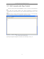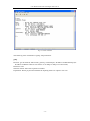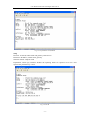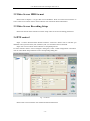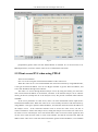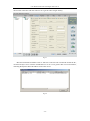
1
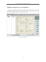
User Manual of DS-6100-ATA Digital Video Server User Manual of DS-6104HCI/6101HFI-ATA Series Video Server User Manual of DS-6100-ATA Digital Video Server Index CHAPTER 1 INTRODUCTION ..................................................................................................................... 4 1.1 FUNCTIONS AND FEATURES ......................................................................................................................... 4 1.2 COMMON APPLICATION ............................................................................................................................... 4 CHAPTER 2 INSTALLATION ....................................................................................................................... 6 2.1 HARDWARE INSTALLATION ......................................................................................................................... 6 2.1.1 Installation steps ................................................................................................................................ 6 2.1.2 Installation notice............................................................................................................................... 6 2.2 HDD INSTALLATION ................................................................................................................................... 6 2.3 PANEL DESCRIPTION .................................................................................................................................... 7 2.4 THE PIN DEFINITION OF PHYSICAL INTERFACES ........................................................................................... 8 2.4.1 PIN definition of RS-232 serial interface .......................................................................................... 8 2.4.2 PIN definition of RS-485 serial interface ........................................................................................ 10 2.4.3 PIN definition of Ethernet interface ................................................................................................. 10 CHAPTER 3 VIDEO SERVER SETUP ....................................................................................................... 12 3.1 PARAMETER SETUP THROUGH RS-232 SERIAL PORT ................................................................................. 12 3.1.1 Hyper Terminal Setup ...................................................................................................................... 12 3.1.2 Shell Commands under Hyper Terminal .......................................................................................... 15 3.2 VIDEO SERVER HDD FORMAT................................................................................................................... 18 3.3 VIDEO SERVER RECORDING SETUP ........................................................................................................... 18 3.4 PTZ CONTROL .......................................................................................................................................... 18 3.5 REMOTE SETUP VIDEO SERVER PARAMETERS ............................................................................................ 19 CHAPTER 4 UPGRADE FIRMWARE ........................................................................................................ 20 4.1 USE SHELL COMMAND AND TFTP SERVER ............................................................................................... 20 4.2 USE CLIENT SOFTWARE TO UPGRADE FIRMWARE ...................................................................................... 23 CHAPTER 5 PPPOE DIALUP OPERATION .............................................................................................. 26 5.1 USING PPPOE TO ESTABLISH CONNECTION .................................................................................................. 26 5.2 CLIENT ACCESS DVS WHEN USING PPPOE ............................................................................................... 27 CHAPTER 6 FREQUENT ASK QUESTIONS ............................................................................................ 29 APPENDIX A SPECIFICATIONS .................................................................................................................. 30 APPENDIX B GOOD LIST ............................................................................................................................ 31 APPENDIX C CUSTOMER INFORMATION CARD ................................................................................... 32 User Manual of DS-6100-ATA Digital Video Server Thanks for purchasing the products of Hikvision. If you have any requests or questions, please contact us immediately. This manual is applicable to DS-6104HCI-ATA & DS-6101HFI-ATA Series Video Server with one IDE HDD interface for local recording. This manual will be updated on a regular basis without additional specific notice. The updates will be added to the new version of this manual. We will readily improve and update the products or procedures described in the manual. -3- User Manual of DS-6100-ATA Digital Video Server Chapter 1 Introduction DS-6104HCI-ATA & DS-6101HFI-ATA series video server adopts embedded Linux OS and TI DaVinci Processor that is completely independent of PC platform, and efficiently improves system performance. Firmware is burned into the FLASH, making the system more steady and reliable. DS-6104HCI-ATA & DS-6101HFI-ATA series video server has the function of compressing the video signal and audio signal simultaneously into H.264 hardware compression standard; transmitting the compression stream through network; real-time video and audio preview; supporting stream protocol (RTP/RTCP, RTSP), supporting IE browser, bi-directional voice talk and multilingual etc. It also supports one HDD for local recording. Notes: DS-6104HCI-ATA: 4 channels video input and 4 channels audio input, can support 4-ch CIF compression resolution real time, or 4-ch DCIF/2CIF at 4fps per channel, or 4-ch 4CIF at 2fps per channel. DS-6104HFI-ATA: One channel video and audio input. It can max support 4CIF resolution real time. If you set the channel frame rate as 4CIF resolution, please set the bit rate as 1.5Mbps above to get the excellent image quality. The default DS-6104HCI-ATA & DS-6101HFI-ATA are without HDDs. 1.1 Functions and features Basic Function: 1. Adopt H.264 video compression and OggVorbis audio compression technology; 2. Multiple security level leads to high system safety; 3. Support one RS-485 interface that can be used for controlling pan-tilt-zoom and translucent channel input; Compression Function 1. 2. 3. 4. 5. DS-6101HFI-ATA supports 4CIF compression resolution real time. DS-6104HCI-ATA can support 4-ch CIF compression resolution real time, or 4-ch DCIF/2CIF at 4fps per channel, or 4-ch 4CIF at 2fps per channel. Support both variable bit rate and variable frame rate. When choosing video image quality, you can also limit the bit rate. Support OSD .The position of the date & time can be changeable. Support LOGO, and the position is adjustable in the video image. Local Recording Function 1. Support multiple record type, including schedule recording, manual recording, motion detection, external alarm, motion&alarm, motion|alarm recording. -4- User Manual of DS-6100-ATA Digital Video Server 2. 3. 4. 5. Support one IDE HDD that can max support 2000GB. Support FAT32 files system Support HDD S.M.A.R.T technology. Support cycle or non-cycle record. Network Function 1. Support one 10M/100M adaptive NIC; 2. Support TCP/IP protocols; support video, audio, alarm, voice data, serial device data transmission through TCP/IP network; build-in WEB browser, support IE access. 3. Support pan-tilt-zoom control such as the turn of PTZ, iris and focus; 4. Support remote upgrade and maintenance; 5. RS-485 interface supports transparent channel, through which the remote host can control serial devices. 1.2 Common application Network digital surveillance, such as factory and the bank etc; Remote monitoring service for prison, nursery and school; Intelligent gate system (dynamic record the people in and out); Intelligent building and community; Self-service system of electric power station or telecom base station; Outdoor equipment monitoring; Bridge, tunnel and cross road-monitoring system; Pipeline, warehouse monitoring; 24 hour monitoring of traffic; Remote monitoring of forest, water and river etc -5- User Manual of DS-6100-ATA Digital Video Server Chapter 2 Installation 2.1 Hardware installation 2.1.1 Installation steps 1. 2. 3. Open packing case, and check the integrity; Take out things needed in installation; Connect cables needed (video signal input cable, audio signal input cable, RS485 cable and cable for LAN); 4. Take out stabilizer power supply and power on. 2.1.2 Installation notice Please read the following notice carefully. If you have any question, please contact us. Notice: 1. After Opening the packing box, please check carefully to confirm that the goods in it are consistent with list; 2. 3. 4. 5. Please read user's manual carefully before installation; Please power-off all related equipments before installation; Please check the voltage of power supply to avoid voltage mismatch; Installation environmental: Do not use it under humidity and high temperature; to keep ventilation to vent freely, avoid to be walled up; to keep them horizontally, avoid to set up in the vibration surroundings. 2.2 HDD Installation Installation notice The DS-6100HCI-ATA has no HDD when leaving factory. Based on the record schedule, you can calculate the total capacity you need (refer to Appendix A). Please ask the specialist to disassembly the video server and install HDD. Installation instrument One cross screw driver HDD installation 1. Open the video box. 2. Place the HDD in the proper space and fix it with screw. -6- User Manual of DS-6100-ATA Digital Video Server 3. Connect the ATA data cable correctly. 4. Plug the HDD power connector. 5. Cover and fix the video server box. Note: After you install the HDD, you must format it. You can use remote client software to format the HDD. 2.3 Panel description Front panel Interface Instruction (From left to right in turn) 1. HDD indicator lamp; 2. Tx/Rx indicator lamp; 3. Link indicator lamp; 4. Power supply indicator lamp; Back panel of DS-6001HFI-ATA Back panel of DS-6004HCI-ATA Interface Instruction (From left to Right in return): 1. One line in audio input for voice talk. -7- User Manual of DS-6100-ATA Digital Video Server 2. 3. 4. 5. 6. One audio output for voice talk. One RJ45 UTP network port and one RJ45 RS-485 PTZ port. 4 external alarm input and 2 relay output. 4 channels video input and audio input. Power supply adapter. 2.4 The pin definition of physical interfaces 2.4.1 PIN definition of RS-232 serial interface The DVS has one RS-232 standard serial interface, with RJ-45 connector. Its pin definition is as follows (‘I’ means input, and ‘O’ means output): (1) When the RS232 interface of the DVS connects with the DTE equipment, one end of the cable is the 8-pin RJ45 connector (to DVS) and the other of the cable is the DB25 female connector (to DTE). Below is the description of the internal connection between RJ45 and DB25. -8- User Manual of DS-6100-ATA Digital Video Server (2) 25-pin to 9-pin converter’s internal connection is like this: (3) If you don’t want to use 25-pin to 9-pin convertor to connect DVS and DTE through RS232 interface, you must use RJ45-DB9 cable. Its internal connection description is: (4) When the RS232 interface of the DVS connects with the DCE (such as MODEM), one end of the cable is the 8-pin RJ45 connector and the other is the DB25 male connector. Below is the description of the internal connection between RJ45 and DB25: -9- User Manual of DS-6100-ATA Digital Video Server 2.4.2 PIN definition of RS-485 serial interface 1 8 TXD+ TXDRXD+ RXDGND 8 7 6 5 2 2.4.3 PIN definition of Ethernet interface (1) PIN definition of the direct network cable connecting DVS and HUB: (2) PIN definition of the cross network cable connecting DVS and host PC: - 10 - User Manual of DS-6100-ATA Digital Video Server - 11 - User Manual of DS-6100-ATA Digital Video Server Chapter 3 Video Server Setup There are three kinds of methods to configure the parameters of video server. 1. Through Hyper Terminal (connect DVS with the PC through RS-232 serial ports) 2. Through client-end application software (connect DVS with PC through network) 3.1 Parameter Setup through RS-232 serial port Mainly set up IP parameters of the video server through serial port. The default IP address is 192.0.0.64. Under the case that the IP address is unknown; the Hyper Terminal or NetTerm (need to connect the serial ports) can be adopted to get or configure IP address and subnet mask. Under the case that IP address is known, client software can be adopted to configure IP address and other parameters. 3.1.1 Hyper Terminal Setup Please direct connect the RS-232 serial port of PC with the RS-232 serial port of video server before configuration (there are RJ45 head and DB9 line in the packing carton) How to establish the connection with the super terminal connection? Step one: Enter into Hyper Terminal. Click “Start” “Programs” “Accessories” “Communications” “Hyper Terminal” in Windows system, and the dialogue box below will appear (Fig. 3.1): Fig. 3.1 Newly establish a connection and define the name and icon - 12 - User Manual of DS-6100-ATA Digital Video Server Step2: To name the connection name and to define the icon. Input a name (e.g. aa), select a icon, press “OK”, the dialogue box like Fig. 3.2 appears. Fig. 3.2 Select communication port Step 3”: to select the communication port. Select “com1” communication port in Fig3.2, press “OK”, the dialogue box as Fig. 3.3 will appear. Fig. 3.3 Serial ports parameter setup Step 4: Serial port parameters setup. Set the serial port parameters as the following setup: Bits per second: 115200, Data bits: 8, Parity: None, Stop bits: 1, Flow control: None. Press “OK” after finish, the Hyper Terminal interface like Fig. 3.4 will appear - 13 - User Manual of DS-6100-ATA Digital Video Server Fig. 3.4 Hyper Terminal Interface Step 5: To close the window, the Fig. 3.5 will appear. Select “Yes” and Fig. 3.6 will appear: Fig. 3.5 Disconnect Fig. 3.6 Save Hyper Terminal session Step 6: Save the Hyper Terminal session for using next time. After saving, it will new establish a “Hyper Terminal” item in the program group “Start” “Programs” “Accessories” “Communications” “Hyper Terminal” and it includes all “Connection” name for all Hyper Terminal. Here you have see “aa.ht”. - 14 - User Manual of DS-6100-ATA Digital Video Server 3.1.2 Shell Commands under Hyper Terminal Please use the DTE cable and the DB9/DB25 convertor to connect PC with DVS RS-232 port. Step 1: Enter into the Hyper Terminal. Click “Start” “Programs” “Accessories” “Communications” “Hyper Terminal” “aa.ht”, the Hyper Terminal interface in Fig. 3.4 will appear. Step 2: Press “Enter” in Hyper Terminal, the prompt “#” appear, as in Fig. 3.7. Under this prompt the following operation commands to accomplish the setup of the parameters. Fig. 3.7 Hyper Terminal command prompt Input help, the supported configuration commands can be checked up, as in Fig. 3.8. - 15 - User Manual of DS-6100-ATA Digital Video Server Fig. 3.8 Check command The following is the introduction of getIp, setIp commands. getIp Function: get the fixed IP, subnet mask, gateway, command port, IP address of PPPoE dialup (the IP address of PPPoE will be 0.0.0.0 if there is no dialup or dialup is not successful). Parameter: none. Grammar format: Enter after input the command Explanation: Please pay attention whether the inputting letters are capital or low case. - 16 - User Manual of DS-6100-ATA Digital Video Server Fig. 3.9 Get parameters of IP, PPPoE setIp Function: set the IP, subnet mask and gateway of the device Parameter: IP address, subnet mask, gateway Grammar format: setIp IP: mask Explanation: Please pay attention whether the inputting letters are capital or low case. And separate the parameters by colons. Fig. 3.10 Set IP - 17 - User Manual of DS-6100-ATA Digital Video Server 3.2 Video Server HDD format Please refer to chapter 3.1 to get video server IP address. Then use remote client software to access video server. Please refer to client software user manual for detail information. 3.3 Video Server Recording Setup Please use remote client software to remote setup video server local recording parameters. 3.4 PTZ control Step1: Connect DS-6100-ATA RS-485 interface with PTZ. Please refer to RS-485 pin definition. DVS just uses Pin8 (TX+) and Pin7 (TX-) to send PTZ control command. Step2: You can use remote client software to setup PTZ protocol. In client software remote “Local Configure” dialog box, select “COM configuration” tab button. You can select DVS PTZ parameters in the corresponding dialog box. Fig. 3.11 RS-485 Please refer to client software user manual for detail information. - 18 - User Manual of DS-6100-ATA Digital Video Server 3.5 Remote setup video server parameters Before the configuration, please make sure that the PC and the video server has been established the network connection, you can confirm using PING command. Please refer to the user manual of DVRDVS client software for detail information. Fig.3.12 Server Configuration - 19 - User Manual of DS-6100-ATA Digital Video Server Chapter 4 Upgrade Firmware There are two methods to upgrade the DVS firmware. One is using shell commands to ask DVS to download firmware from TFTP server. The other is using PC client software. 4.1 Use Shell Command and TFTP Server Step 1: Before the update start you should do the follow steps: 1. Download the TFTP server from the internet, such as Cisco TFTP Server. Then put the firmware in the root directory of the Cisco TFTP Server. 2. Connect the device to the Router. 3. Please use DTE cable to connect device 232 port with COM port of the server PC. 4. Configure the Hyper Terminal. Steps as below. Enter into start----all programs----accessories------communications-----hyper terminal. Click hyper terminal. 1) Input the name “aa”. And do the step 1 again. Then enter into Fig 4.2. Select COM1 and click “OK” to enter into Fig 3. Fig 4.1 2) Fig 4.2 Modify the bits per second to ‘115200’. and modify the flow control to’ None.’ Finally click “apply” and “ok” to enter into the hyper terminal main interface. - 20 - User Manual of DS-6100-ATA Digital Video Server Fig 4.3 Step 2: Then reboot the device and press any button in the pc keyboard again and again until the HIK # come out in the Hyper Terminal interface, show as Fig 4.4. Then input the “print” to check if the IP of the server and device is correct, also both of them should be in the same LAN. you can use the command “set serverip” to modified the server ip “set ipaddr” to modified the device ip “set netmask” to modified the mask ip Show as the Fig.4.5. Fig 4.4 - 21 - User Manual of DS-6100-ATA Digital Video Server Fig 4.5 Step 3: Input commend “save” and press enter button. Show as Fig.4.5. Step 4: Input the commend “update” and press enter button, then space button. After that the update will start. Show as Fig.4.6 Fig. 4.6 - 22 - User Manual of DS-6100-ATA Digital Video Server Step 5: After the update finished, please input the command “reset” and press the enter button. The device will reset. Show as Fig.4.7. Fig 4.7 4.2 Use Client Software to upgrade firmware In the system setup dialog of DVRDVS client software (refer to client software user manual), there is a button named “Other”: - 23 - User Manual of DS-6100-ATA Digital Video Server Fig.4.8 Remote upgrading Click “Explore” button and select the firmware file. Fig.4.9 Then click “Upgrade” button, to complete the upgrading process of the video server firmware. - 24 - User Manual of DS-6100-ATA Digital Video Server Fig.4.10 - 25 - User Manual of DS-6100-ATA Digital Video Server Chapter 5 PPPoE Dialup Operation DS-6100-ATA video server supports remote access through network, through browser, through PPPoE or PPP dialup. Before using this function, please make sure that the software you used in your device support such functions or not. 5.1 Using PPPoE to establish connection In the local LAN, use the client software remote setup the DVS parameters. The setup dialog is looked as following: Fig.5.1 In the server parameters sub dialog, enable PPPoE function, input the correct PPPoE user name and PPPoE password. Click “Confirm” button and “Save Para.” button. The new server parameters will be saved into video server through network. Reboot the video server, the DVS will start to dialup the internet. After success, the video server will get a dynamic WAN IP address. - 26 - User Manual of DS-6100-ATA Digital Video Server Fig.5.2 [Explanation] please make sure that ADSL Modem is installed. If it is the first time to set PPPoE parameters, it needs to reboot video server to establish the connection. 5.2 Client access DVS when using PPPoE There are two methods: One is to access using the current WAN IP address of the video server. When the video server is successful establish the network connection by using PPPoE mode, it will get the WAN IP address. You can use Hyper Terminal to get the WAN IP address, and access this IP address through client software. The other is to access through domain analysis server. By using this mode, you need a PC with a fixed WAN IP address in the Internet, and there is the domain analysis server software running in this PC (actually this PC is the analysis server). We provide such demo DNS software and SDK. In the server parameters of video server, there is an item named DNS. Please input the PC fixed WAN IP address here. When the video server is successfully connection with the internet by using PPPoE, it will get a dynamic WAN IP address, and send the name and current IP address to the analysis server. If the client-end software wants to access the video server, it’d first to connect with the PC used as the analysis server, telling the analysis server which one video server he wants to access. The analysis server will search all the video servers have been registered, find out the server with the same name or same serial number, and tell the client-end the WAN IP address of the video server. After the client-end software get the current IP address, it can establish - 27 - User Manual of DS-6100-ATA Digital Video Server the network connection with the video server to get the video images directly. Fig.5.3 Here the fixed WAN IP address of PC is 220.184.114.48. We call it as DNS IP. In that the PC, one demo analysis server software named IP Server is run. It can get the video server information, including the dynamic WAN IP address of the video server. Fig.5.4 - 28 - User Manual of DS-6100-ATA Digital Video Server Chapter 6 Frequent Ask Questions 1. Failure to control PTZ It is possible that the camera and equipment are not connected through RS485 port, or the wrong configuration of the decoder. 2. certain individual channel picture is un-normal Please check whether the video cable is well connected with the camera and the Embedded DVS 3. Possible reasons which can cause the failure of upgrading Failure of the network, IP address error in the FTP host computer, FTP service is not been booted by PC, the path to upgrade is not correct; no permission (usually happened when to upgrade through client-end.) If the above information cannot meet your demand, please not hesitate to contact the provider. - 29 - User Manual of DS-6100-ATA Digital Video Server Appendix A Specifications Model DS-6101HFI-ATA Video compression H.264 Encode/Decode resolution 4CIF/DCIF/2CIF/CIF/QCIF Video input 1 Video input interface BNC(1.0Vp-p, 75Ω ), Support PAL, NTSC Frame channel) 4CIF: 25(P)/30(N) fps rate(per DS-6104HCI-ATA 4 4CIF: 2 fps DCIF/2CIF: 4fps CIF: 25(P)/30(N) fps Stream types Video/Video&Audio Support dual stream Yes Bit rate 32Kbps ~ 2Mbps adaptive. (Max. 8Mps) Audio input 1 Audio input interface BNC (2Vp-p, 1kΩ) Audio output 1 channel RCA(linear electrical level, 600Ω) Audio compression OggVorbis, 16Kbps Voice talk 1 channel RCA (2Vp-p, 1kΩ) Communication interface 1 RJ45 10M/100M Adaptive Ethernet port, 1 RS232 interface and 1 RS485 interface IDE interface 1 interface with 1 built-in IDE hard disk, the maximum capacity is 2000GB Alarm input 4 Alarm output 2 Power supply 100~240V AC, 6.3A, 50~60Hz Power consumption 20~30W (without HDD) Working temperature -10℃~+55℃ Working humidity 10%~90% Size(mm) 78mm(H)*350mm(W)*225mm(D) Weight ≤3.5Kg(without HDD) 4 - 30 - User Manual of DS-6100-ATA Digital Video Server Appendix B Good list 1. One piece of DS- 6100HCI-ATA video server; 2. One CD contains client application and user manual; 3. One power cable; 4. One DTE cable; - 31 - User Manual of DS-6100-ATA Digital Video Server Appendix C Customer Information Card User’s Name Company Name Post Address Postcode Phone Number E-mail Model Number of Product Serial Number of Product Purchase Date Distributor Suggestions: Mr./Mrs. - 32 -