1
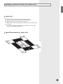
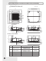
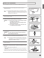
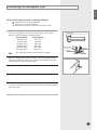
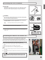
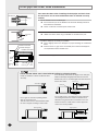
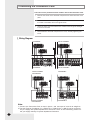
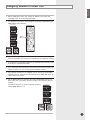
ENGLISH ENGLISH RUSSIAN EΛΛHNIKA System Air Conditioner (Cooling and Heating) DEUTSCH PORTUGUÊS ITALIANO FRANÇAIS CHEAM(1)C Series ESPAÑOL INSTALLATION MANUAL E S F I P D G R DB98-26330A(4) Safety Precautions The following safety precautions must be taken when using your air conditioner. WARNING Installing the unit Risk of electric shock. • Can cause injury or death. • Disconnect all remote electric power supplies before servicing, installing or cleaning. • This must be done by the manufacturer or its service agent or a similar qualified person in order to avoid a hazard. The unit should not be installed by the user. Ask the dealer or authorized company to install the units except room air conditioners for the U.S.A and Canada area. If the unit is installed improperly, water leakage, electric shock or fire may result. Mount with the lowest moving parts at least 2.5 m above the floor or grade level. (If applicable) The manufacturer does not assume responsibility for accidents or injury caused by an incorrectly installed air conditioner. If you are unsure about installation, contact an installation specialist. When installing the built-in type air conditioner, keep all electrical cables such as the power cable and the connection cord in pipe, ducts, cable channels e.t.c to protect them against liquids, outside impacts and so on. Power supplyline, fuse or circuit breaker E-2 If the power cord of this air conditioner is damaged, it must be replaced by the manufacturer, its service agent or similarly qualified persons in order to avoid a hazard. The unit must be plugged into an independent circuit if applicable or connect the power cable to the auxiliary circuit breaker. An all pole disconnection from the power supply must be incorporated in the fixed wiring with a contact opening of >3mm. Do not use an extension cord with this product. If the unit is equipped with a power supply cord and a plug, the plug must be accessible after installation. The air conditioner must be installed in accordance with national wiring regulations and safety regulations wherever applicable. ENGLISH Contents Preparation for Installation ............................................................................................................... Deciding Where to Install the Indoor Unit ................................................................................ Indoor Unit Installation ........................................................................................................................ Purging the Unit ..................................................................................................................................... Connecting the Refrigerant Pipe ................................................................................................... Cutting / Flaring the Pipes ................................................................................................................ Performing Leak Test & Insulation .............................................................................................. Connecting the Cables to the Outdoor Unit ............................................................................. Drainpipe and Drain Hose Installation ....................................................................................... Connecting the Connection Cord ................................................................................................. Assigning Address to Indoor Unit ................................................................................................. Installing the Safety Net ..................................................................................................................... Troubleshooting ...................................................................................................................................... Parts List (Optional) ............................................................................................................................. 4 5 7 8 9 10 11 11 12 14 15 16 17 20 E-3 Preparation for Installation When deciding on the location of the air conditioner with the owner, the following restrictions must be taken into account. General Do NOT install the air conditioner in a location where it will come into contact with the following elements: Combustible gases Saline air Machine oil Sulphide gas Special environmental conditions If you must install the unit in such conditions, first consult your dealer. Accessories The following accessories are supplied with the indoor unit. The type and quantity may differ depending on the specifications. E-4 Pattern sheet Insulation cover drain Insulation pipe Insulation drain hose M4x12 tapped Screw Pad stopper Safety net M4x12 tapped Screw Insulation Cable-tie Installation manual Insulation cover band Flexible hose ENGLISH Deciding Where to Install the Indoor Unit Indoor Unit There must be no obstacles near the air inlet and outlet. Install the indoor unit on a ceiling that can support its weight. Maintain sufficient clearance around the indoor unit. Make sure that the water dripping from the drain hose runs away correctly and safely. The indoor unit must be installed in this way, that they are out of public access. (Not touchable by the users) Space Requirements for Indoor Unit E-5 Deciding Where to Install the Indoor Unit (continued) Drawing of the indoor unit Unit : mm 860~690 (Ceiling opening) 950 860~690(Ceiling opening) 950 766(Suspension) 699(Suspension position) 260 290 25 208 100 80 230 160 190 57 840 25 322 242 246 305 1000mm or more Required space 41 64 218 57 166 344 178Adjustable “A” Model: CH052/070/094EAMC CH070EAM1C Branch duct connection “B” Model: CH105/140EAMC 258Adjustable 57 57 840 25 260 25 No. E-6 208 305 Name 1 Liquid pipe connection 2 Gas pipe connection 3 4 5 6 Drain pipe connection Power supply connection Air discharge grille Air suction grille "A"Model CH052EAMC/CH070EAM1C:ø6.35(1/4") CH070EAMC:ø9.52(3/8") CH094EAMC:ø9.52(3/8") CH052EAMC:ø12.7(1/2") CH070EAM(1)C:ø15.88(5/8") CH094EAMC:ø15.88(5/8") "B"Model ø9.52(3/8") ø19.05(3/4") Required space 246 1000mm or more Branch duct connection 242 322 68 158 138 160 190 64 310 200 41 298 457 290 Indoor Unit Installation 1 Place the pattern sheet on the ceiling at the spot where you want to install the indoor unit. Note 2 ENGLISH It is recommended to install the piping joint before installing the indoor unit. Since the diagram is made of paper, it may shrink or stretch slightly due to temperature or humidity. For this reason, before drilling the holes maintain the correct dimensions between the markings; refer to page 5 or 6. Insert bolt anchors, use existing ceiling supports or construct a suitable support as shown in figure. Concrete Insert 3 Install the suspension bolts depending on the ceiling type. IMPORTANT 4 Ceiling support You must install the suspension bolts more than four when installing the indoor unit. Hang the indoor unit to the suspension bolts between two nuts. Note 6 Suspension bolt(M8)-field supply Screw eight nuts to the suspension bolts making space for hanging the indoor unit. IMPORTANT 5 Ensure that the ceiling is strong enough to support the weight of the indoor unit. Before hanging the unit, test the strength of each attached suspension bolt. If the length of suspension bolt is more than 1.5m, it is required to prevent vibration. Hole in anchor Hole in plug Piping must be laid and connected inside the ceiling when suspending the unit. If the ceiling is already constructed,lay the piping into position for connection to the unit before placing the unit inside the ceiling. Pad stopper Bracket Screw the nuts to suspend the unit. Cut a pad stopper and place it on the bracket at this time. 7 Adjust the unit to the appropriate position considering the installation area for the front panel. 7-1 Place the pattern sheet on the indoor unit. 7-2 Adjust a space between the ceiling and the indoor unit by using the gauge of dimensions. 7-3 Fix the indoor unit securely after adjusting level of the unit by using a leveler. 7-4 Remove the pattern sheet, connect the other cables and install the front panel. Indoor Unit 20mm Ceiling 17mm Gauge of Dimensions E-7 Purging the Unit On delivery, the indoor unit is loaded with refrigerant gas. All this gas must therefore be purged before connecting the assembly piping. To purge the inert gas, proceed as follows. Liquid refrigerant port Unscrew the pinch pipe at the end of each refrigerant pipe. Result: All inert gas escapes from the indoor unit. Note Gas refrigerant port E-8 To prevent dirt or foreign objects from getting into the pipes during installation, do NOT remove the pinch pipe completely until you are ready to connect the piping. ENGLISH Connecting the Refrigerant Pipe There are two refrigerant pipes of differing diameters: A smaller one for the liquid refrigerant A larger one for the gas refrigerant The inside of copper pipe must be clean & has no dust. 1 Remove the pinch pipe on the pipes and connect the assembly pipes to each pipe, tightening the nuts, first manually and then with a torque wrench, a spanner applying the following torque. Outer Diameter 6.35 mm (1/4") 9.52 mm (3/8") 12.70 mm (1/2") 15.88 mm (5/8") 19.05 mm (3/4") 22.23 mm (7/8") Note Torque (kgf•cm) 140~170 250~280 380~420 440~480 990~1210 990~1210 If the pipes must be shortened refer to page10. 2 Must use insulator which is thick enough to cover the refrigerant pipe to protect the condensate water on the outside of pipe falling onto the floor and the efficiency of the unit will be better. 3 Cut off any excess foam insulation. 4 Be sure that there must be no crack or wave on the bended area. 5 It would be necessary to double the insulation thickness (10mm or more) to prevent condensation even on the insulator when if the installed area is warm and humid. Refrigerant oil Torque wrench Spanner Flare nut Union E-9 Cutting/Flaring the Pipes 1 Make sure that you have the required tools available (pipe cutter, reamer, flaring tool and pipe holder). 2 If you wish to shorten the pipes, cut it with a pipe cutter, taking care to ensure that the cut edge remains at a 90° angle with the side of the pipe. Refer to the illustrations below for examples of edges cut correctly and incorrectly. 90 O Oblique Rough Burr 3 To prevent any gas from leaking out, remove all burrs at the cut edge of the pipe, using a reamer. 4 Slide a flare nut on to the pipe and modify the flare. Outer Diameter (D) 6.35 mm (1/4") 9.52 mm (3/8") 12.70 mm (1/2") 15.88 mm (5/8") 19.05 mm (3/4") 22.23 mm (7/8") 5 Check that the flaring is correct, referring to the illustrations below for examples of incorrect flaring. Inclined 6 Depth (A) 1.3mm 1.8mm 2.0mm 2.2mm 2.2mm 2.2mm Damaged Surface Cracked Uneven Thickness Align the pipes and tighten the flare nuts first manually and then with a torque wrench, applying the following torque. Outer Diameter 6.35 mm (1/4") 9.52 mm (3/8") 12.70 mm (1/2") 15.88 mm (5/8") 19.05 mm (3/4") 22.23 mm (7/8") Torque (kgf•cm) 140~170 250~280 380~420 440~480 990~1210 990~1210 CAUTION In case of welding the pipe, you must weld with nitrogen gas blowing. E-10 ENGLISH Performing Leak Test & Insulation Leak Test To check for gas leaks on the indoor unit, check the connection part of each refrigerant pipe by using a leak detector. Insulation No gap Once you have checked that there are no leaks in the system, you can insulate the piping and hose. 1 To avoid condensation problems, place T13.0 or thicker Acrylonitrile Butadiene Rubber around each refrigerant pipe. Note NBR(T13.0 or thicker) Always make the seam of pipes face upwards. Insulation cover pipe Insulation pipe 2 Wind insulating tape around the pipes and drain hose. 3 Finish wrapping insulating tape around the rest of the pipes leading to the outdoor unit. Indoor Unit Be sure to overlap the insulation CAUTION Must fit tightly against body without any gap. Connecting the Cables to the Outdoor Unit Two electric cables must be connected to the outdoor unit. The connection cord connecting the indoor unit to the outdoor unit The power cable connecting the auxiliary circuit breaker to the outdoor unit 1.Remove the terminal board cover on the side of the outdoor unit. 2.Connect the connection cord and power cable to terminals as shown in the diagram. 3.Connect the power cable to the auxiliary circuit breaker. 4.Replace the terminal board cover, carefully tightening the screw. Note: The connect cables should be incert from the front,use rubber-wire to protect the cables. Use hold-wire to fasten the cables,ensure the cables can not touch the comp and pipes CAUTION Keep the power cable and the connection cord in a steel pipe to protect them against liquids, outside impacts and so on. E-11 Drain pipe and Drain Hose Installation Flexible hose Drainpipe Drain hose port Care must be taken when installing the drainpipe and drain hose for the indoor unit so that condensate water is drained correctly outside. 1 Fix the flexible hose to the drainpipe. The connection port of the flexible hose and PVC drainpipe must be fixed with PVC adhesives. Check out that the connected part doesn’t leak. 2 Connect the flexible hose to the flexible hose port. Make sure that a rubber ring is installed on the drain hose port. 3 Install the drainpipe as shortly as possible. Give a slightly slant to the drainpipe for proper drainage of condensate water. There must be no gap on the connected part so that the drainpipe is not separated from the flexible hose . 4 Insulate the drainpipe, and then fix it as indicated. Insulation cover band Insulation drainpipe Insulation cover drain Indoor Unit Band(Not supplied) Drain hose port Flexible hose Adhesives Band Drain hose Band CAUTION Check that the indoor unit is level with the ceiling by using the leveler. If it is necessary to increase the height of the drain pipe, install the drainpipe straightly within 300 mm from the flexible hose port. If it is raised higher than 550 mm,there can be water leaks. 300mm or less Air ventilation 20mm or more Band joint 1/100 or more 550mm or less Install air ventilation to drain condensate water smoothly. Flexible hose Ceiling Do not give the hose and upward gradient after the connection port. This will cause water to flow backwards when the unit is stopped, resulting in water leaks. Ceiling Do not apply force to the piping on the unit side when connecting the drain hose. The hose should not be allowed to hang loose from its connection to the unit. Fasten the hose to a wall, frame or other support as close to the unit as possible. Support pieces Upward gradient 1~1.5m 1/100 or more Ceiling E-12 Ceiling Note ENGLISH Drain pipe and Drain Hose Installation (continued) If a concentrated drain hose is installed, refer to the figure below. Drain clamp 1/100 or more slope 100mm or more Air ventilation Concentrated drain hose Testing the drainage You should test the drainage after completing the installation. Prepare a little water about 2.0 liters. 1 Turn the cover drain pump, then pull it out. 2 Pour water into the indoor unit as shown in figure. Cover drain pump Note 3 If you do not pour water inside the water supply intake, water may spill from the indoor unit. Confirm that the water flows out through the drain hose. Note 4 You can check the drainage only when the air conditioner is in cool mode. Reassemble the cover drain pump. E-13 Connecting the Connection Cord The indoor unit is powered from the outdoor unit via the connection cord. 1 Remove the screw on the electrical component box and remove the cover plate. 2 Route the connection cord through the side of the indoor unit and connect the cable to terminals; refer to the figure below. 3 Route the other end of the cable to the outdoor unit through the ceiling & the hole on the wall. 4 Reassemble the electrical component box cover, carefully tightening the screw. Wiring Diagram Note : CH105EAMC CH140/105EAMC UH105EAMC UH140/105GAMC CH052/070EAMC CH070EAM1C CH094EAMC UH052/070EAMC UH070EAM1C UH094EAM1C 1. Connect the Connection Cord as seen in picture , and the torque of screw is 40~70kgf•cm . 2. The Split Type Air Conditioner CHEAM(1)C(CHEAM(1)C/ UHAM(1)C) can be connected only to a supply with system impedance no more than 0.177Ω. In case necessary, please consult your supply authority for system impedance information. E-14 ENGLISH Assigning Address to Indoor Unit 1 Before installing the indoor unit, assign an address to the indoor unit according to the air conditioning system plan. 2 The address of the indoor unit is assigned by adjusting MAIN(SW02) and RMC(SW04) rotary switches. SW05 K1 K2 K3 K4 SW06 K5 K6 K7 K8 SW07 K9 K10 K11 K12 SW02 MAIN SW04 RMC The MAIN address is for communication between the indoor unit and the out door unit. Therefore, you must set it to operate the air conditioner properly. 4 It is required to set the RMC address if you install the wired remote control ler and/or the centralized controller. 5 If you install optional accessories such as the wired remote controller, cen tralized controller, etc. see an appropriate installation manual. 6 If an optional accessory is not installed, you do not have to set the RMC address. However, adjust K1 and K2 switches of the SW05 DIP switch to "ON" position in this case. 7 Set the MAIN address by adjusting the rotary switch(SW02) from 0 to 9. Each indoor unit connected to the same outdoor unit must have different address. K1 K2 K3 K4 If an indoor unit does not have an optional accessory and its MAIN address is "0" SW05 3 SW06 K5 K6 K7 K8 SW07 K9 K10 K11 K12 SW02 MAIN SW04 RMC E-15 Installing the Safety Net Install the safety net after installing the connection cord and fixing electric component box cover. For your safety, you must install the safety net.For details about installing the panel, refer to the manual for the panel. 1 Uncover the wrap of safety net. 2 Fix the safety net to the electric component cover box with four screws as indicated. The electric component box cover The safety net E-16 ENGLISH Troubleshooting Detection of errors If an error occurs during the operation, one or more LED flickers and the operation is stopped except the LED. If you re-operate the air conditioner, it operates normally at first, then detect an error again. LED Display on the receiver & display unit LED Display LED lamp display Operation Defrost Abnormal conditions Timer Air flow Filter Remarks Type A Type B Power reset X X X X X X Error of heat exchanger sensor in the indoor unit X X X Error of the outdoor temperature sensor Error of the condensor temperature sensor Error of the discharge temperature sensor X Error of temperature sensor in the indoor unit (Open/Short) X X X X 1. No communication for 2 minutes between indoor units 1. Indoor unit error (Display is unrelated with operation) (Communication error for more than 2 minutes) 2. Indoor unit receiving the communication error from outdoor unit 3. Outdoor unit tracking 3 minutes error X X X 2. Outdoor unit error (Display is unrelated with operation) 4. When sending the communication error from the outdoor unit, the mismatching of the communication numbers and installed numbers after completion of tracking (Communication error for more than 2 minutes) On Flickering X Off If you turn off the air conditioner when the LED is flickering, the LED is also turned off. E-17 Troubleshooting (continued) LED Display LED lamp display Operation Defrost Abnormal conditions Timer Air flow Filter Remarks Type A Type B Communication error between indoor units X X X 1. Error of electronic expansion valve close 2. Error of electronic expansion valve open 3. 2’nd detection of high temperature cond 4. 2’nd detection of high temperature discharge X X Detection of the float switch X X Error of setting option switches for optional accessories X X 5. Error of reverse phase 6. Compressor down due to 6’th detection of freezing EEPROM error X X X X EEPROM option error On Flickering X Off If you turn off the air conditioner when the LED is flickering, the LED is also turned off. E-18 ENGLISH Wired remote controller If an error occurs, is displayed on the wired remote controller. u If you would like to see an error code, press the Test button. Display Explanation Compressor down due to protection control of the discharge temperature sensor Control due to the condenser temperature sensor when cooling mode Remark Error about protection control of the outdoor unit Error of the low pressure switch (Protection control) Reverse phase error (Protection control) In removing frost Error of the outdoor temperature sensor (Open/Short) Error of condensor temperature sensor (Open/Short) Error of discharge temperature sensor (Open/Short) - System down caused by communication error after completion of tracking Error about the outdoor unit sensor (Open/Short)Detection during the operation of the indoor unit (sensing and sending errors into the communication data) Communication and the indoor unit errors - Mismatching of the indoor unit numbers set with those communication after completion of 5 times tracking Error of temperature sensor in the indoor unit (Open/Short) Self-diagnosis of the indoor and outdoor unit Error of the heat exchanger sensor in the indoor unit (Open/Short) Error of electronic expansion valve open in the outdoor unit (when it is detected more than once) Error of electronic expansion valve close in the outdoor unit (when it is detected more than once) Error of communication between the indoor unit and the wired remote controller Wired remote controller errors Master wired remote controller Slave wired remote controller COM1/COM2 Cross-installed error Error of setting option for wired remote controller COM2 E-19 Parts List (Optional) Wired Remote Controller Accessories Wired remote controller Cable-tie Cable clamp 1 2 5 7 1 Wire joint Owner’s instructions Installation manual 1 1 1 Communication cable of the wired remote controller 1 M4x16 tapped Indoor unit power screw drawing cable Wireless Remote Controller Accessories Wireless remote controller Battery 1 2 STS 2S-2x10 Remote control holder tapped screw 1 2 Owner’s instructions Installation manual 1 1 Owner’s instructions Installation manual 1 1 Centralized Controller Accessories E-20 Centralized controller Cable-tie 1 2 Cable clamp M4x16 tapped screw 5 7 ENGLISH Function Controller Accessories Function controller Cable-tie 1 2 Cable clamp M4x16 tapped screw 6 7 Owner’s instructions Installation manual 1 1 Transmitter Accessories Transmitter Transmitter power cable Transmitter communication cable Installation manual 1 1 1 1 Note If you would like to install the centralized controller, you must install the transmitter in the outdoor unit. 7-day Scheduler Accessories 7-day Scheduler Cable-tie 1 2 Cable clamp M4x16 tapped screw 2 4 Owner’s instructions Installation manual 1 1 E-21 MEMO E-22 E-23 ENGLISH