1
IMPORTANT MANUAL
Do Not Throw Away
J _/AJRS
Operator's
Manual
Model No
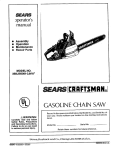
CRAFTSMAN"
358.351240
Always
ASSISTANCE
Wear Eye Protection
(:RAFTSMANo
3.7 cu. in./60cc 2-CYCLE ENGINE
24 Inch Guide Bar
GASOLINE CHAIN SAW
WARNING:
READ THE OPERATOR'S
MANUAL AND FOLLOW
ALL
WARNINGS
AND
SAFETY INSTRUCTIONS,
FAILURE TO DO SO CAN
RESULT
IN
SERIOUS
INJURY.
• Assembly
• Operation
• Customer Responsibilities
° Service and Adjustments
• Repair Parts
Sears, Roebuck and Co, Hoffman Estates, IL 60179 USA
530-083882-2-08/03/95
SAFETY RULES
r
WARNING:
ALWAYS DISCONNECT SPARK PLUG WIRE AND PLACE WIRE WHERE IT CANNOT CONTACT SPARK
PLUG TO PREVENT ACCIDENTAL STARTING WHEN SETTING UP, TRANSPORTING, ADJUSTING OR
MAKING REPAIRS EXCEPT CARBURETOR ADJUSTMENTS.
BECAUSE A CHAIN SAW IS A HIGH-SPEED WOOD-CUTTING TOOL, SPECIAL SAFETY PRECAUTIONS
MUST BE OBSERVEDTO REDUCETHE RISK OF ACCIDENTS. CARELESS OR IMPROPER USE OFTHtS
TOOL CAN CAUSE SERIOUS INJURY.
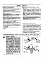
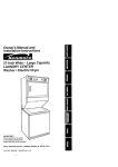
Hearing
Safety Hat
Protection _..___.
Snug
| _
!1
,J_/_'_"---
Fitting
Clothing
,_F I'_k
Eye Protection
Heavy Duty Gloves
€. - .,,i
Safety Chaps
Safety
Shoes
Figure 1
KNOW YOUR SAW
- Read your operator's manual carefully untilyoucompletely understandand can follow all safety rules, precautions,and
operating instructions before attempting to operate the unit
• Restrict the use of your saw to adult users who understand and can fo!low safety rules, precautions,and operating
instructionsfound in this manual
PLAN AHEAD
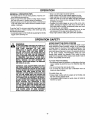
• Wear protective gear. Figure 1. Always use steel.toedsafety footwear with non-slip soles; snug-F_tingclothing; heavy
duty, non-slip gloves; eye protection such as non-fogging,
vented goggles or face screen; an approved safety hard hat;
and sound barriers - ear plugs or mufflers to protectyour
hearing.Regular users should have hearing checked regular
ly as chain saw noise can damage hearing_
• Keep all parts of your body away from the chainwhen the
engine is running.
• Keep children,bystanders, and animals a minimumof 30
feet (10 meters) away from the work area. Do not atlow
other people or animals to be near the chain saw when starting or operating the chain saw.
• Do not handle or operate a chain saw when you are
fatigued, ill, or upset,or if you have takenalcohol,drugs,
or medication. You must be in good physicalcond_onand
mentally alert Chain saw work is strenuous.If you have any
condition that might be aggravated by strenuouswork, check
with your doctor before operatinga chain saw.
• Do not attempt to use your chain saw during bad weather conditions such as strongwind, rain,snow, ice,etc. or at
night
• Carefully plan your sawing operation in advance.Do not
start cutting until you have a cleat work area, secure footing,
and, if you are fellingtrees, a planned retreatpath
, Do not operate a chain saw that is damaged,improperly
adjusted, or not completely and securely assembled.
Always replace the handguardimmediatelyif it becomes
damaged, broken,or is otherwise removed.
, Keep the handles dry, clean,and free of oil or fuel mixlure.
o With the engine stopped,hand carry the chain saw with
the muffler away from your body, and the guide bat and
chain to the rear, preferablycovered with a scabbard.
FUEL HANDLING
- Eliminate all sources of spar'Ksor flames in the areas
where fuel is mixed, poured,or stored.Thereshould be no
smoking, open flames, or wood that could cause sparks.
Allow engine to cool beforerefueling.
• Mix and pour fuel in an outdoor area on bare ground;store
fuel in a cool, dry, wellventilatedplace; and use an approved,
marked container for att fuel purposes.
• Wipe up all fuel spills before starting saw.
° Move at least 10 feet (3 meters) from the fueling site
before starting the engine.
• Do not smoke while handlingfuel or while operating the
saw.
° Turn the engine off and let your saw cool in a non-combustible area, not on dry leaves, straw,paper;etc, Stowly
remove fuel cap and refuel unit.
, Store the unit and fuel in an area where fuel vapors cannot
reach sparks or open flames from water heaters, electdc
motors or switches, furnaces,etc.
SAFETY NOTICE
Exposure to vibrations through prolonged use of gasoline powered hand tools could cause b_oodvessel or nerve damage in Ihe fingers, hands, and joints of people prone to circulationdisorders or abnormal sweIlings_ Prolonged use in cold weather has been linked
to blood vessel damage in otherwise healthy people,if symptoms occur such as numbness, pain loss of strength change in skin color
or texture, or loss of fee ngs n the f ngers, hands or joints, discontinue the use of this toot and seek medical attention. An anti-vibra.
lionsystem does not guarantee the avoidance of these problems..Users who operate power tools on a continual and regular basis must
monitorclosely their physical conditionand the conditionof this unit.
LOOK FOR THIS SYMBOLTO POINT OUT IMPORTANT SAFETY PRECAUTIONS.
IT MEANS - ATTENTION!!! BECOME ALERT!!! YOUR SAFETY IS INVOLVED.
SAFETY RULES
OPERATEYOUR
SAW SAFELY
. Do not operate a chain saw with one hand.Serious injury
to the operator, helpers, bystanders or any combination of
these persons may result from one-handed operation. A
chain saw is intended for two-handed use.
- Operate the chain saw only in well-ventilated outdoor
areas,
- Do not operate saw from a ladder or in a tree, unless
specifically trained to do soo
• Position all parts of your body to the left of cut and
away from the chain when the engine is running,
. Cut wood only. Do not use yoursaw to pry or shove away
limbs,roots, or other objects,
• Make sure the chain will not make contact with any
object while starting the engine. Never try to start the
saw when the guide bar is in a cutor keff,
. Use extreme caution when cutting small size brush and
saplings. Slender material can catch the chain and be
whippedtoward you or pull you off balance..
- Be alert for springbeck when cutting a limb that is under
tension so you wilt not be struck by the limb or saw when
the tension in the wood fibersis released.
• Do not put pressure on the saw at the end of a cuL
Applying pressure can cause you to lose control when the
cut is completed.
Stop the engine before setting the saw down.
, Keep fuel and oil caps, screws, and fasteners securely
tightened,
GUARD AGAINST
MAINTAIN YOUR SAW IN GOOD WORKING
ORDER
• Have all chain saw service performed by your Sears
Service Center with the exceptionof the itemslistedin the
"Customer Responsibilities" section of this manua!.. For
example, if improper tools are used to remove or hold the
flywheel when servicing the clutch, structural damage to the
flywheel can occur and cause the flywheel to burst.
. Make certain the chain stops moving when the throttle
trigger is released. For correction, refer to "Carburetor
Adjustments:'
. Stop the saw if the chain strikes a foreign object.
Inspectunitand repairor replace partsas necessary,
• Disconnect the spark plug before performing any maintenance except for carburetor adjustments.
- Never modify your saw in any way. Use only SEARS
accessories and replacement parts as recommended
TRANSPORTING
AND STORAGE
o Stop the unit before transporting.
• Allow engine to cool, cover the guide bar and chain, and
secure the unit before storing or transporting in a vehicle.
• Empty fuel tank before storing or transportingthe unit..Use
up any fuel left in the carburetor by starting the engine and
letting the engine run until it stops.
• Store unit and fuel in an area where fuel vapors cannot
reach sparks or open flames from water heaters, electric
motors or switches, furnaces, etc.
• Store unit so the chain cannot accidentallycause iniury.
. Store the unit out of the reach of children°
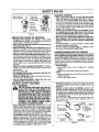
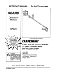
KICKBACK - Kickback is a dangerous reaction that can lead to serious injury.
KICKBACK WARNING:
KICKBACK
CAN OCCUR WHEN THE
MOVING CHAIN CONTACTS AN OBJECT AT
THE UPPER PORTION OF THE TIP OF THE
GUIDE BAR OR WHEN THE WOOD CLOSES
IN AND PINCHES THE CHAIN IN THE CUT.
CONTACT ATTHE UPPER PORTION OFTHE
TIP OF THE GUIDE BAR CAN CAUSE THE
CHAIN TO DIG INTO THE OBJECT, WHICH
STOPS THE CHAIN FOR AN INSTANT. THE
RESULT IS A LIGHTNING FAST, REVERSE
REACTION WHICH KICKS THE GUIDE BAR
UP AND BACK TOWARDTHE OPERATOR. IF
THE CHAIN IS PINCHED ALONG THE TOP
OF THE GUIDE BAR, THE GUIDE BAR CAN
BE DRIVEN RAPIDLY BACK TOWARD THE
OPERATOR. EITHER OFTHESE REACTIONS
CAN CAUSE LOSS OF SAW CONTROL
WHICH CAN RESULT IN SERIOUS INJURY.
DO NOT RELY ONLY ON THE SAFETY
DEVICES PROVIDED WITH YOUR SAW. AS A
CHAIN SAW USER, YOU MUST TAKE SPECIAL SAFETY PRECAUTIONS TO HELP
KEEP YOUR CUTTING JOBS FREE FROM
ACCIDENT OR INJURY_
Kickback
Path
Figure 2
Avoid
Obstructions
Clear The
Working Area
Figure 3
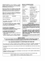
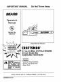
SAFETY RULES
Thumb On
Under Si
Of Handlebar
Never Reverse
|
Hand Positi_
11
/4
Elbow
\
Stand To
The Left
Of The Saw
Figure 4
REDUCETHE
CHANCE OF KICKBACK
° Recognize that kickback can happen. With a basic
understandingof kickback, you can reduce the element of
surprise which contributes to accidents,,
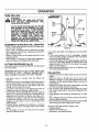
• Never let the moving chain contact any object at the tip
of the guide bar. Figure 2.
. Keep the working area free from obstructions such as
othertrees,branches, rocks, fences, stumps,etc. Figure3.
Eliminateor avoid any obstruction that yourchain could hit
whileyou are cuttingthrougha particularlog or branch_
- Keep your chain sharp and properly tensioned. A loose
or'dutlchaincan increase the chance of kickback to occur.
Followmanufacturer's chain sharpeningand maintenance
instructionsCheck tension at regular intervals with the
engine stopped, never with the engine running_ Make sure
the bar clamp nuts are securely tightenedafter tensioning
the chain_
• Begin and continue cutting at full throttle. If the chainis
moving at a slower speed, there is greaterchance for kickback to occur,
• Cut one log at a time.
• Use extreme caution when re-entering a previous cut,
= Do not attempt plunge cuts.
• Watch for shifting logs or other forcesthat could closea
cut and pinchor fat! intochain,.
- Use the Reduced-Kickback Guide Bar and LowKickback Chain specifiedfor your saw.
KICKBACK SAFETY FEATURES
THE FOLLOWING FEATURES ARE INCLUDWARNING:
ED ON YOUR SAW TO HELP REDUCE THE
HAZARD OF KICKBACK; HOWEVER, SUCH
FEATURES WILL NOT TOTALLY ELIMINATE
THIS DANGEROUS REACTION. AS A CHAIN
SAW USER, DO NOT RELY ONLY ON SAFETY
DEVICES.YOU MUST FOLLOW ALL SAFETY
PRECAUTIONS, INSTRUCTIONS, AND MAINTENANCE IN THIS MANUALTO HELP AVOID
KICKBACK AND OTHER FORCES WHICH
CAN RESULT IN SERIOUS INJURY.
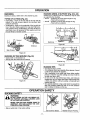
Reduced-Kickback Guide Bar, designed with a small
radiustip which reduces the size of the kickback danger
zone on the guide bar tip. Figure 5. A Reduced-Kickback
Guide Bar is one which has been demonstrated to significantly reduce the number and seriousness of kickbacks
when tested in accordance with ANSI BI75,1-199l.
• Low-Kickback Chain, designed with a contoured depth
gauge and guard link which deflect kickback force and
allow woodto gradually ride intothe cutter:Figure 5. LowKickbackChain is chain which has met kickback performance requirements of ANSI B175,,1-1991 when tested
on a representativesample of chain saws below 3.8 cubic
inchdisplacement specified in ANSI B175_1-1991.
_4_
l_
MAINTAIN CONTROL
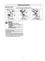
. Keep a good, firm grip on the saw with both hands
when the engine is running and don't let go. Figure4.
A firm gdp can neutralizekickback and help you maintain
control of the saw. Keep the fingers of your left hand encircling and your left thumb under the front handlebar: Keep
your right hand completely around the rear handle whether
you are right handed or left handed_Keep your left arm
straight with the elbow locked.
° Position your left hand on the front handlebar so it is
in a straight line with your right hand on the rear handle when making bucking cuts, Figure4. Never' reverse
right and left hand positions for any typeof cutting.
o Stand with your weight evenly balanced on both feet.
, Stand slightly to the left side of the saw to keep your
body from being in a direct line with the cutting chain.
Figure 4.
• Do not overreach. You could be drawn or thrown off balance and lose control of the saw.
o Do not cut above shoulder height. It isdifficult to maintaln controlof saw above shoulder height.
UNDERSTANDING
REACTIVE FORCES
Pinch-Kickback and PulHn occur when the chain is suddenly stopped by being pinched, caught, or by contacting a foreign object in the wood_Thisstoppingofthechain
results in a reversalof the chainforce used to cut woodand
causes the saw to move in the opposite direction of the chain
rotation,.Either reaction can result in loss of control and possible serious injury.
• Pinch-Kickback
-occurs when chain on top of guide bar is suddenly
stopped.
- rapidly drives saw straight back toward operator.
• Puff-In
- occurs when the chain on the bottom of the guide bar is
suddenly stopped,.
- pulls the saw rapidly forward
• Handguard, designed to reduce the chance of your left
hand contacting the chain if your hand slips off the front
handlebar_
• Position of front and rear handlebars, designed with
distance between handles and "in-line" with each other:
The spread and "imline" positionof the hands providedby
this design work together to give balance and resistance
in controllingthe pivotof the saw back toward the operatot if kickbackoccurs
• ANSI B175 1-199! _ Safety requirements for gasotine powered chain
saws as set by the American National Standards Insl_tute, Inc,
Standard B175.1-1991.
Reduc_ Kickba_k
Symt_elt_c_ Guido B_r
R_dius T_p
'_
G_t_e Bat
Radiu_ "_p
Figure 5
ChtJ_ With High
K_k_ck
ForintS!
Can C_struct
CONGRATULATIONS
on your purchase
of a Sears
Craftsman
Gasoline Chain Saw. It has been designed,
engineered and manufactured
to give you the best possibte dependability and pefformance_
PRODUCT
SPECIFICATIONS
GUIDE BAR: .................. 24" (61cm)
CHAIN: ..............................Low Proffie 3/8" Pitch
Chrome Cutters
Should you experience any problems you cannot easily
remedy, please contact your nearest Sears Service Center/Department° Sears has competent, well trained technicians and the proper tools to service or repair this unit
DISPLACEMENT:
........ 3..7 Cubic Inches (60cc)
ENGINE: .................................
2-cycle Air Cooled
FUEL MIX: .............................
40:1 (3.2 oz.,oil per gallon gas)
Please read and retain this manual,.The instructions will
enabte you to assemble and maintain your unit properly.
Always observe the "SAFETY RULES."
MODEL NUMBER:
OILER: .................................
Adjustable,
10.4 oz.,Tank
IGNITION: .........................Solid State
(Air gap .008" to .014")
IGNITION TIMING: ....... Non-adjustable, fixed
358.351240
SPARK PLUG TYPE: .,.Champion (CJ-6Y)
DATE CODE/SERIAL NOD:
SPARK PLUG GAP: ..... 025" (,65mm)
DATE OF PURCHASE:
MUFFLER: .........................
Spark Arresting Screen
THE MODEL AND SERIAL
FOUND ON THE PRODUC_
NUMBER
WILL BE
ENGINE RPM: ...............12,700 RPM Maximum
with Bar and Chain
SPECIAL NOTICE
Your saw is equipped with a temperature limiting muffler and spark arresting screen which meets the requirements of California Codes 4442 and 4443. All US forest
land and the states of California, Idaho, Maine, Minnesota,
New Jersey, Washington, and Oregon require many intema]
combustion engines to be equipped wilh a spark arrestor
screen by law.
YOU SHOULD RECORD BOTH SERIAL NUMBER
AND DATE OF PURCHASE AND KEEP tN A SAFE
PLACE FOR FUTURE REFERENCE°
MAINTENANCE
AGREEMENT
A Sears Maintenance Agreement is available on this product. Contact your nearest Sears Store for details
CUSTOMER
If you operate a chain saw in a state or locale where
such regulations exist, you are legally responsible for
maintaining the operating condition of these parts.
Failure to do so is a violation of the law. Refer to the
Spark Arrestor section under "Customer
Respons|bilities"for maintenance.
RESPONSIBILITIES
° Read and observe the safety ruleso
- Follow a regular schedule in maintaining, caring for, and
using your unit.
o Follow the instructions under "Customer Responsibilities" and =Storage" sections of this Operator's Manual..
MANUFACTURED
UNDER ONE OR MORE OF THE FOLLOWING U5 PATENTS:
5.367 988; 4,940.028; 4,370,855; 4302.879; 4 197 6_0; D325.330 OTHER US. AND FOR e
EIGN PATENTS PENDING
SPECIAL NOTICE
If this saw is to be used for commercial logging, you must order and install a Chain Brake, to comply with
Federal OSHA Regulations for Commercial Logging. See Repair Parts List or call 1-800-235-5878.
FULL ONE YEAR WARRANTY ON CRAFTSMAN
GAS CHAIN SAW
For one year from the date of purchase, when this Craftsman Gas Chain Saw is maintained, lubricated and
tuned-up according to the owners manual, Sears will repair, free of charge, any defect in material or workmanship.
This warranty excludes the bar, chain, spark plug and air filter, which are expendable parts, and become worn during
normal use.
If this Gas Chain Saw is usecl for commercial or rental purposes this warranty applies for 30 days from the date of
purchase.
WARRANTY SERVICE IS AVAILABLE BY RETURNING THIS CHAIN SAW TO THE NEAREST SEARS SERVICE
CENTER IN THE UNITED STATES.
This warranty gives you specific legal rights, and you may also have other rights which vary from state to state.
SEARS, ROEBUCK AND CO. D/817WA, Hoffman Estates, IL 60179
-5 _
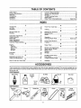
TABLE OF CONTENTS
Safety Rules ...........................................................................................
2
Customer Responsibilities ..............................................................
19
Product Specifications
5
Service and Adjustments ...........................................................
24
Warranty ..............................................................................................
5
Storage ....................................................................................
29
Accessories................................................................................................
6
Trouble Shooting Points ..................................................................
30
Assembly ....................................................................................................
7
Repair Parts ......................................................................................
31
Operation ................................................................................................
10
Repair' Parts Ordering/Service
..................................
Back Cover
......................................................................................
INDEX
.............................................................................................
A
K
Accessories
6
Know Your Chain Saw .......................................................................
10
Air Filter...................................................................................................
22
L
Assembly ...................................................................................................
7
Limbing ..................................................................................................
18
B
M
Bar and Chain Oil
12
Maintenance Schedule .................................................................
19
B ucking .......................................................................................
17
Model Number .....................................................................................
5
C
Muffler ..............................................................................................
22
O
Carburetor Adjustments .................................................................
27
Carton Contents ...............................................................................
7
Operation ...............................................................................
10
Chain Oiler ...........................................................................................
!1
Ordering Repair Parts ...........................................
Back Cover
P
Chain Sharpening ..................................................................................
20
Chain Adjustment ........................................................................
24
Product Specifications ............................................................
5
Customer Responsibilities .....................................................
19
Pruning....................................................................................
18
E
R
Engine
Repair Parts ...........................................................................
3t
Fuel/Oil.......................................................................................
12
S
Spark Plug .........................................................................................
22
Service and Adjustments .............................................................
24
Starting .....................................................................................................
!3
Spark Arrestor Screen ....................................................... 22
Storage ...........................................................................................
29
Starter Rope ............................................................................
25
F
Starting
13
Fuel Filter .........................................................................................
23
Storage .........................................................................................
29
Fueling......................................................................................................
12
T
G
Throttle Control Group ..................................................... 11
Guide Bar and Chain Oil .......................................................
I2
Tree Felling.............................................................................
15
Guide Bar Maintenance
21
Trouble Shooting Points .......................................................
30
H
W
HowTo Use Your Chain Saw............................................ 11
Warranty..................................................................................
5
............................................................................
........................................................................................
............................................................
ACCESSORIES
These accessories and attachments were available when the unit was originally purchased.They are also available at most
Sears retail outletsand service centers°Most Sears stores can order these items for you when you providethe model number'of your unit.
PERFORMANCE
Spark Plug
2-cycle
Air Filter'
Bar Oil
Gas Can
Oil
Engine&2 oz,
1 qt.
1 gaL
8 oz_
16 oz_
MAINTENANCE
Carrying
Gloves
Guide Bar'
/
Safety
Goggles
-6-
Chain
Hearing
Protection
Chain
Sharpener
2' f
CARTON CONTENTS
Hex Key
_J
Bucking Spike
Illllllll
Chain Saw
_,.m+
FueI/Oil Mix
(Bar Oil Not included)
Purchase Craftsman Bar
and Chain Oil Separately
_Chain
!
Operator's Manual
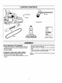
ASSEMBLY
TOOLS REQUIRED
• After removing the contents from the carton, check parts
against the Carton Contents list.
• Examine the parts for damage. Do not use damaged
parts+
• If parts are missing or damaged please carl the 1+800
number listed on the front of this manual
FOR ASSEMBLY
• Torque Wrench (optional) - Reference torque values are
provided throughout this manual for tightening hardware
• BarTool (included)
• Hex Key (included)
TO REMOVE CHAIN SAW FROM CARTON
NOTE: tt is normal to hear the fuel filter rattle in an empty
fuel tank.
• Remove looseparts bag included with Chain Saw_
• Remove your saw from the packing material
• You may use the opened packing material as a work
surface,,
-7-
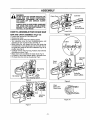
ASSEMBLY
DANGER:
DO NOT START THE ENGINE WITHOUT THE
GUIDE BAR AND CHAIN COMPLETELY
ASSEMBLED° OTHERWISE, THE CLUTCH
CAN COME OFF AND SERIOUS INJURY
CAN RESULT.
Guide Bar
Clutch Drum
ALWAYS WEAR GLOVES WHEN HANDLING
THE CHAIN, THE CHAIN CAN BE SHARP
ENOUGH TO CUT YOU EVEN THOUGH W IS
TOO DULL TO CUT WOOD.
HOWTO
ASSEMBLEYOUR
CHAIN
Mourltin_; Bolts
Lower Hole
SAW
Figure 8
BAR AND CHAIN ASSEMBLY (Fig.6-12)
,
=
°
=
=
°
=
o
Loosen and remove the 2 bar clamp nuts°
Remove bar clamp.
Remove and throw away blue shipping spacer:
Turn adjusting screw by hand counterclockwise untii
adjusting pin just touches the stop (see Fig. 7)..
Mount guide bar with slotted end over both guide bar
mounting bolts. Insert adjusting pin into the lower hole in
the guide bar. Install the bar with "Craftsman" logo in up
position (see Fig. 8)_
Carefully remove chain from bag. Position chain with the
drive links as shown Fig,.9.
Place chain over and behind the clutch drum. Fig..10..
Fit bottom of drive links between teeth in sprocket nose.
Fit chain drive links into top of guide bar: Fig. 9.
Clutch
Drum
Bar Clamp
Nuts
Bar
Blue Shi
Spacer
Figure6
Figure 9
Chain
Behind The
Clutch Drum
Screw
Figure 10
Figure7
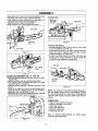
ASSEMBLY
• Move guide bar forward by turning the adjusting screw
clockwise until chain is snug in guide bar grooves.
o Now, install bar clamp making sure the adjusting pin is
positioned in the lower hole in the guide bar,
Install two (2) bar clamp nuts finger tight
,_ Now proceed to the "Chain Adjustment section.
Guide Bar
/
Guide Bar
t
Figure t4
Adjusting
Pin
"__
To check chain tension:
• Use the screwdriver end of the bar tool to move chain
around the g[,tidebar (see Fig. 15)_
• If chain does not rotate, it is too tight - slightly loosen bar
clamp nuts and turn adjusting screw 1/4 turn counterclockwise. Retighten bar clamp nuts.
• If chain is too loose, loosen bar clamp nuts; then, turn
adjusting screw 1/4 turn clockwise, Lift up tip of guide bar
to check for sag Retighten bar clamp nuts,
-Bar Clamp
Figure 11
Bar Tool
/
Bar Clamp
Nuts
Guide Bar
t
Figure 12
CHAIN ADJUSTMENT
(Fig, 13, 14 8= 15)
Roll chain around guide bar to ensure kinks do not exist,
(rotates freely).
Adjusting
Screw
Assure bar clamp nuts are loosened (finger tight).
Turn adjusting screw clockwise until chain just barely
touches the bottom ot guide bar.
= Roll chain around guide bar to ensure all links are in bar
groove..
• Lift up tip of guide bar to check for sag., Release tip of
guide bar, then turn adjustingscrew 1/4 turn clockwise.
Repeat thisstep until sag does not exist..
• While lifting tip of guide bar, tighten bar clamp nuts with
the bar tool(provided). Torque 10-15 ft-lbs.
Figure 15
NOTE - It is normal for a new chain to stretch, Because of
this initial stretch during the first 15-30 minutes of opera.
lion, you should recheck your chain tension frequently and
adjust the chain tension as required. (See "Chain Tension"
section).
CHECK LIST
•
•
•
•
•
•
Check for loosefasteners and parts.
Check for damaged or worn parts°
Check chain tension,
Check chain sharpness_
Guide bar maintenance.
Check guide bar lube,
Refer to "Customer Responsibilities"
ments and recommendations_
Figure 13
-9_
for further adjust-
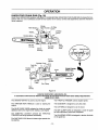
OPERATION
KNOWYOUR
CHAIN SAW (Fig. 16)
READ THIS OPERATOR'S MANUAL AND SAFETY RULES BEFORE OPERATING YOUR CHAIN SAW. Compare the illustrations with your unit to familiarize yourself with the location of the various controls and adjustments_ Save this manual for
future reference
Starter
Rope Handte Air Fi}ter
Cover
Hand Guam/
OrVStop
Switch
Bucking Spike __
Bar Oil
Filf Cap
/
Starter
Housing
Blue
Choke
Knob
Fuel Mix
Fill Cap
Front
Handle
CHAIN TRAVEL
DIRECTION
Throttle
Trigger
Bar Clamp
Nuts
Guide Bar
Bar Clamp
Rear
Handle
Figure 16
Listed by Underwriters Laboratories, Inc.
in accordance with American National Standards for Gasoline-Powered Chain Saws Safety Requirements
(ANSI B175.1-1991).
The ON/STOP SWITCH is used to stop the engine.
The THROTTLE TRIGGER controts engine speed,
The STARTER ROPE HANDLE is used for starting tile
engine.
Th_ GUIDE BAR is designed to carry the chain_,
The CUTTERS are designed to cut the wood.
The BLUE CHOKE KNOB activates the choke to provide
additional fuel to the engine when starting a cold engine.
The BAR CLAMP NUTS are designed to hold the guide
bar after adjustments have been completed.
The THROTTLE LOCKOUT prevents the THROTTLE
TRIGGER from being squeezed accidentally_
The ADJUSTING SCREW is designed to tension the chain
on the guide bar:
The FAST IDLE LOCK allows for faster engine speeds during starting,
-10-
OPERATION
HOW TO USE YOUR CHAIN SAW
STOPPING
YOUR ENGINE
. Move on/stop switch to the "Stop" position,.
• If engine does not stop, pul_ btue choke knob out fully_
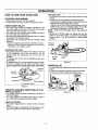
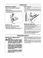
CHAIN OILER (Fig. 17)
• The chain oiler provides continuous lubrication to the
chain and guide bar_ Be sure to fill the bar oi] tank when
you fill the fuel tank (Capacity = !0o4 fL oz.),,
• Your chain saw will consume approximately one tank of
bar oil for each tank of fuel used
• Your saw is equipped with an adjustable oiler. It is preset
at the factory, to maximum output,.
• Adjustment may be necessary for the following cutting
situations:
- less oil is required for soft wood or freshly cut wood.
- maximum oil is required for hardwood or wood which
has been cut for a period of time.
ADJUSTING THE OILER
• The adjusting screw is located at the bottom of the saw
on the crankcase next to the bar clamp° It can be
adjusted with the screwdriver end of the bar tool
provided.
. To increase the oil flow, turn the adjusting screw counterclockwise.
• To decrease the flow, turn the adjusting screw clockwise,,
• Be sure to readjust the oiler before returning to other
types of cutting which require higher Ievels of lubrication,,
Bar Oil
_
/_
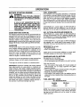
FAST IDLE LOCK
- The fast idle lock atlows for faster engine speeds during
starting_
• The fast idle lock is engaged by the following steps:
- Grasp the rear handle and depress the throttle lockout.
- Squeeze the throttle trigger fully and hold.
- Depress the fast idle lock with your forefinger and holdo
- Release your grip on the throttle trigger and throttle
lockout while continuing to hold the fast idle lock,.
NOTE - Verify the throttle trigger stays in the advanced
position.
= Squeezing the throttle trigger wiU release the fast idle
setting,, If the throttle trigger is squeezed accidentally
during starting, it will be necessary to reset throttle
advance,,
Throttle
Lockout
Throttle
Trigger
Fast Idle
Lock
Figure 18
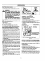
CHOKE (Fig. 19)
• The choke provides additional fuel when starting a cold
engine,,
. The choke is activated by pulling the blue choke knob°
• The choke has three positions: off, partial and full,
Fue! Mix
On/Stop
_;N _._sToP
Front Handle
Choke Positions
Oil Adjusting Screw
OFF
PARTIAL
Figure 17
THROTTLE
CONTROL
J
r
GROUP (Fig. 18 & 19)
THROTTLE LOCKOUT
• The throttle lockout prevents unintentional actuation of
the throttle trigger.
• You must depress the throttle lockout with the palm of
your hand before actuating the throttle trigger.
Figure 19
THROTTLE TRIGGER
• The throttle trigger allows for variable control of engine
speed.
• The throttle trigger is actuated by the indexfinger on your
right hand. (After the throttle lockoutis depressed)
-11 -
b _' 1
FULL
OPERATION
BEFORE
STARTING
FUEL STABILIZER
ENGINE
Fuel stabilizer is an acceptable alternative in minimizing
the formation of fuel gum deposits during storage, Add stabilizer' to gasoline in fuel tank or storage container,. Always
follow the fuel mix ratio found on the stabilizer container,
Run engine at least 5 minutes after adding stabiIizer to
allow the stabilizer' to reach the carburetor.You do not have
to drain the fuel tank for storage if you are using fuel stabilizer.
WARNING:
BE SURE TO READ THE FUEL HANDLING
INFORMATION IN THE SAFETY RULES SECTION ON PAGE 20FTHtS MANUAL BEFORE
YOU BEGIN,
IF YOU DO NOT UNDERSTAND THE FUEL
HANDUNG SECTION DO NOT ATTEMPTTO
FUEL YOUR UNIT; SEEK HELP FROM
SOMEONE THAT DOES UNDERSTAND THE
FUEL HANDLING SECTION OR CALL THE
CUSTOMER
ASSISTANCE HOTLtNE AT
1_800--235-5878.
CRAFTSMAN 40:1 2-cycte engine oil (AIR-COOLED) is
specially blended with fuel stabilizers° If you do not use
this Sears oil, you can add a fuel stabilizer to your fuel tank.,
40:1 2-CYCLE
GUIDE BAR AND CHAIN OIL
AIR-COOLED
ENGINE OIL
CRAFTSMAN 40:1 2-cycle engine oil (AIR-COOLED) is
strongly recommended. This oil is specially blended with
fuel stabilizers for increased fuet stability (extends fuel life
up to 5 times longer) and reduced smoke,.
For maximum guide bar and chain life, we recommend you
use Craftsman chain saw bar oil, If Craftsman bar oil is not
available, you may use a good grade SAE30 oil until you
are able to obtain Craftsman brand.The oil output is automatically metered during operation_ Your saw will use
approximately one tank of bar oil for every tank of fuel mix°
Always fill the bar oil tank when you fill the fuel tank.
If CRAFTSMAN 40:1 2*cycle engine oil (AIR-COOLED) is
not available, use a good quality 2-cycle engine oil (AIR..
COOLED) that has a recommended fuel mix ratio of 40:1.
GASOLINE
IMPORTANT! Do not use:
- AUTOMOTIVE OIL.
o BOAT OILS (NMMA, BIA, etc.)
The two-cycle engine on this product requires a fuel mixture of regular unleaded gasoline and a high quality 40:1
2-cycle engine oil (AIR-COOLED) for lubrication of the
bearings and other moving parts.The correct fuetloit mixture is 40:1 (see Fuel Mixture Chart). Too little oil or the
incorrect oil type will cause poor performance and may
cause the engine to overheat and seize.
These oils do not have proper additives for 2-cycle (AIRCOOLED) engines and can cause engine damage
GASOLINE
AND OIL MIXTURE
Mix gasoline and oii as follows:
.Consuft chart for correctquantities.
° Do not mix gasolineand oil directly in the unit's fuel tank°
Gasoline and oil must be premixed in a clean approved fuel
container, Always use fresh regular unleaded gasoline°
This engine is certified to operate on unleaded gasoline.,
IMPORTANT: Experience indicates that alcohol blended
fuels called gasohol (or using ethanol or methanol) car!
attract moisture, which leads to oittgas separation and formation of acids during storage. Acidic gas can damage the
fuel system of an engine while in storage.To avoid engine
problems, the fuel system should be emptied before storage for 30 days or longer° Drain the gas tank, then runthe
fuel out of the carburetor and fuel lines by starting the
engine and letting it run until it stops.. Use fresh fuel next
season. See STORAGE instructionsfor additional informa.tion. Never use engine or carburetor cleaner products in
the fuel tank or permanent damage may occur_
FOR ONE GALLON:
• Pour 3.2 ounces of high quality, 40:1 2-cycle engine oil
(AIR-COOLED) into an empty, approved one gallon
gasoline container.
• Add one gallon of regular unleaded gasoline to the gallon
container, then securely replace the cap.
- Shake the container momentarily.
• The mixture is now ready for use. Fuel stabilizer can be
added at this time if desired;follow mixing instructions on
the label.,
FUEL MIXTURE
CHART
40:1 Fue!:Oil Mix Ratio
l
1 gallon
2.5
Gasoline
gallons
3.2
Oi! 8,0
(fl,oz,)
NOTE: Fuel containers may hold more than the specified
amount, If too much gasoline is in the container, the resulting gas-to-oil fuel mixture will not be correct for proper
engine cperation_
-12-
OPERATION
STOPPING YOUR ENGINE
• Move on/stop switch to the "Stop" position_
° If engine does not stop, pull blue choke knob out fuily.
_lh
On/Stop
ON_ STOP
WARNING:
ALWAYS WEAR GLOVES, SAFETY FOOTWEAR, SNUG-FITTING
CLOTHING, AND
EYE, HEARING, AND HEAD PROTECTION
DEVICES WHEN OPERATING A CHAIN SAWn
THE CHAIN MUST NOT MOVE WHEN THE
ENGINE RUNS AT IDLE SPEED. REFER TO
THE "CARBURETOR ADJUSTMENTS" SECTION FOR CORRECTION.
AVOID ANY CONTACT WITH THE MUFFLER.
A HOT MUFFLER CAN CAUSE SERIOUS
BURNS,
NOTE: Check chain tension using instructions in the
"Service and Adjustment" section,
• Before first use.
• After 1 minute of operation
TO START
ENGINE
(Fig. 20 & 21)
COLD ENGINE START AND WARM ENGINE
START AFTER RUNNING OUT OF FUEL
• Fuel engine with 40:1 fuel mix (3.2 oz. to 1 ga!, gas).
• Fill bar oil tank with bar oil. Your saw will use approximately one tank of bar oil for each tank of fuet mix.
- Turn on ignition by moving on/stop switch to the "On"
position,
• Actuate choke by pulling blue choke knob fully out.Then
set the saw on the ground. Grip the front handle with your
left hand and place your right foot throughthe opening in
the rear handle
= Set fast idle by depressing the throttle lock with your right
hand. Then squeeze throttle trigger and hold. With your
forefinger, press the fast idle lock and hold_Next, release
the throttle trigger.
• IFTHROTTLETRIGGER IS SQUEEZED ACCIDENTALLY DURING STARTING IT WILL BE NECESSARY TO
RESET THE FAST IDLE LOCK.
NOTE: When pulling the starter rope, do not use the full
extent of the rope as this can cause the rope to break. Do
not let the starter snap back, hold the handle and let the
rope rewind slowly
° Pull starter rope handle with your right hand until the
engine attempts to start, Then push the blue choke knob
in to the partial position. Resume pulling handle until
engine starts.
• Above 40 degrees, allow engine to run for approximately 5 seconds, push the choke knob in to the "Off"
position, then squeeze and release throttle trigger to
allow engine to idle.
• Below 40 degrees, allow engine to warm up 30 seconds
- 1 minute with choke at partial position. Push choke
knob in to the "Off" position, then squeeze and release
throttle trigger to allow engine to idle,
• To stop engine, move on/stop switch to the "Stop" positiono
Choke Positions
OFF
PARTIAL
FULL
•J _'.j
Figure 20
STARTING A WARM ENGINE
•
"
,
•
Move on/stop switch to the "On" position
Activate fast idle control
Be sure choke is in the "Off" position_
With saw on ground, grip front handle with left hand and
place your right foot through opening in rear handle°
- Pull starter rope handle until engine starts,
- Squeeze and release throttle trigger to return engine to
idle speed.
Starter Rope Handle
Right Hand on
,
_._k,L-,_"_
, LkJ .4"
",
Starting Position
Left Hand on
k".Z2YI/Front
.andle
Right Foot through opening in Rear Handle
Figure 21
DIFFICULT STARTING OR FLOODED
ENGINE
The engine may be floodedwith too much fuel if it has not
started after 10 pulls,with the choke in the fullout position,
Flooded engines can be cleared of excess fuel with the
following procedure:
• Activate the fast idte Iock
= Verify that the on/stop switch is in the "On" position,
• Push the choke knob to the "Off" position.
= With saw on ground, grip front handle with left hand and
place right foot through opening in rear handle.
- Pull starter rope handle until engine starts.
Starting could require pulling starter rope handle many
times depending on how badly unit is flooded. If engine still
fails to start, refer to 'q'ROUBLE SHOOTING" chart or call
the 1-800 number listed on the front page of this manual
OPERATION
GENERAL
OPERATION
TIPS
*
•
*
°
Never cut with engine at partial speeds.
Begin cutting with the saw chassis against the logo
Keep engine at full throttle during cutting procedure_
Allow the chain to cut for you; exert only light downward
pressure If you force the cut, damage to the bar, chain,
or engine can result.
o Release the throttle trigger as soon as the cut is completed, allowing the engine to idle. If you run the unit at
full throttle without cutting, unnecessary wear' can occur
to the chain, bar', and engine.
° To avoid losing control when completing the cut, do not
put pressure on the saw during the end of the cuL
o Stop engine before setting unit down after cperationo
• Cut wood only. Do not cut metal; plastics; masonry; nonwood building materials; etc.
° Stop the saw if the chain strikes a foreign object. Inspect
the saw and repair' or replace parts as necessary.
• Keep the chain out of dirt and sand.,Even a small amount
of dirt wilt quickly dull a chain and thus increase the possibility of kickback_
To get the "feel" of using your saw before you begin a major
sawing operation, practice cutting a few small logs using
the following technique:
• Accelerate engine to full throttle by squeezing the throttle
trigger' before entering cut.
OPERATION SAFETY
AVOID REACTIVE
WARNING:
PINCH FORCES
Pinch-Kickback and Pull-In occur when the chain is suddenly stopped by being pinched, caught, or by contacting
a foreign object in the wood, This sudden stopping of the
chain results in a reversal of the chain force used to cut
wood and causes the saw to move in the opposite direction
of the chain rotation. Pinch-Kickback drives the saw
straight back toward the operator. Pull-in pulls the saw
away from the operator: Either reaction can result in loss of
control and possibty serious injury°
IF SAW BECOMES PINCHED OR HUNG IN A
LOG, DO NOT TRY TO FORCE IT OUT. YOU
CAN LOSE CONTROL OF THE SAW
RESULTING IN INJURY AND/OR DAMAGE
TO THE SAW. STOP THE SAW, DRIVE A
WEDGE OF PLASTIC OR WOOD INTO THE
CUT UNTIL THE SAW CAN BE REMOVED
EASILY. RESTARTTHE SAW AND CAREFULLY REENTER THE CUT. TO AVOID KICKBACK AND CHAIN DAMAGE, DO NOT USE A
METAL WEDGE. DO NOT ATTEMPT TO
RESTART YOUR SAW WHEN IT IS PINCHED
OR HUNG IN A LOG.
TO AVOID PINCH-KICKBACK:
• Be extremely aware of situations or obstructions that can
cause material to pinch the top of cr otherwise stop the
chain_
= Do not cut more than one log at a time
= Do not twist the saw as the bar is withdrawn from an
under.cut when bucking°
KICKBACK CAN OCCUR WHEN THE MOVING CHAIN CONTACTS AN OBJECT AT THE
UPPER PORTION OFTHE TIP OFTHE GUIDE
BAR OR WHENTHE WOOD CLOSES IN AND
PINCHES THE SAW CHAIN IN THE CUT.
CONTACT ATTHE UPPER PORTION OFTHE
TIP OF THE GUIDE BAR CAN CAUSE THE
CHAIN TO DIG tNTOTHE OBJECT AND STOP
THE CHAIN FOR AN INSTANT.THE RESULT
IS A LIGHTNING FAST, REVERSE REACTION
WHICH KICKS THE GUIDE BAR UP AND
BACK TOWARD THE OPERATOR. IF THE
SAW CHAIN IS PINCHED ALONG THE TOP
OF THE GUIDE BAR, THE GUIDE BAR CAN
BE DRIVEN RAPIDLY BACK TOWARD THE
OPERATOR. EITHER OFTHESE REACTIONS
CAN CAUSE LOSS OF SAW CONTROL
WHICH CAN RESULT IN SERIOUS INJURY.
TO AVOID PULL-IN:
,, Always begin cutting with the engine at full throttle and
the saw housing against wood.
= Use wedges made of plastic or wood, (never' of metal) to
hold the cut open,
14-
OPERATION
TREE FELLING
Felling Direction
WARNING:
IF THE TRUNK OR LIMBS ARE ROTTING,
THEY CAN FALL UNEXPECTEDLY
AND
CAUSE SERIOUS INJURY.
AS YOU MAKE YOUR FELLING CUT, IF THE
SAW APPEARS TO BE BINDING, THE TREE
IS STARTING TO FALL IN THE WRONG
DIRECTION. IMMEDIATELY STOP THE SAW
AND USE A FELLING WEDGE AND MAUL
(HAMMER) TO FORCE THE FELLING CUT
OPEN. THE WEDGE WILL HOLD THE
FELLING CUT OPEN ALLOWING YOU TO
REMOVETHE SAW. KEEP EVERYONE AWAY
FROM THE TREE IN ALL DIRECTIONS.
DETERMINETHE
NATURAL
Bottom
Notch
Cut
I
I
I
Buttress
Root
FALL DIRECTION
• Wind - A tree evenly balanced will fall in the same direction the wind is blowing.
• Lean - Use a carpenter's level or plumb bob to determine if tree has a natural leano A leaning tree will tend to
fall in direction of leano
• Shape - A tree will tend to fall towards side that is more
heavily branched.
• Other Factors - Contacting or nearby trees, buildings, or
wires can influence the direction the tree will fall.
Figure 22
If your chain saw binds in the felling cut, you have three
options:
• If the wrong direction of fall is acceptable, carefully
remove the felling wedge°Cut deeper in the notchside of
the tree until tree starts to fall.
. If the wrong direction of fall is not acceptable, attempt to
use one or more felling wedges to force the tree in the
original direction of fall Do so by driving the wedges
deeper into the felling cut°
• Keep everyone away from the tree in all directions and
then seek professional help!
CUTTING
PROCEDURE
(Fig. 22)
After determining the Natural Fall Direction, the tree should
be cut as follows:
IMPORTANT: BEFORE FELLING A TREE, MAKE SURE
YOU HAVE AT LEAST 3 FELLING WEDGES AND A
MAUL (HAMMER) AVAILABLE FOR USE IF NEEDED°
• Use some means to visually mark the Natural Fail
Direction,
• Mark your notch cut on the Natural Fall Direction side of
the tree approximately 18-24 inches above the ground,r
• Cut top of the notch first at a 45 degree angle° Saw
through 1/3 of the width of the tree,
• Cut bottom of the notch at a 45 degree angle until you
meet the top notch cuL Remove notch of wood.
• On the side of the tree opposite the notch cut, make the
felling cut.The foiling cut should be 2 inches above the
center point of the notch cuL Before the felling cut is
complete, use wedges to open the cut when necessary
to control the direction of the fall.. Use wood or plastic
wedges, but never steel or iron, to avoid kickback and
chain damager
• Cracking sounds, widening of the felling cut, movement
in the upper branches are all signs that the tree is ready
to fall,
• As tree begins to fall, turn off saw, and move quickly
away from direction of fall.
-15-
FELLING TiPS
• Clear the work area ofdebris where you can have secure
footing,.
. Make sure there is enough room for the tree to fall,
Maintain a distance of 2 1/2 tree lengths from the nearest person or other objects. Engine noise can drown out
a warning call
• Remove dirt, stones, loose bark, nails, staples, and wire
from the tree where cuts are to be made.
° Plan to stand on the up-hill side when cutting on a sloper
• Plan a clear retreat path to the rear and diagonal to the
line of fall.
* Large buttress roots should be removed prior to notch
cut.
. Use a wedge if there is any chance that the tree will not
fall in the desired direction.
. We recommend you cut branches below shoulder height
before felling tree,,(See Limbing and Pruning).
Be alert to signs that the tree is ready to fall:
• Cracking sounds.
• Widening of the felling cut.
• Movement in the upper branches_
OPERATION SAFETY
FELLING
SAFETY
DON'T PUT YOURSELF INTHESE POSITIONS
U
Check the wind Don't cut down wind
_hb
Check the lean Don't cut on down side
DOARNING:
NOT CUT:
- NEAR ELECTRICAL WIRES OR
BUILDINGS.
- IFYOU DO NOT KNOW'THE DIRECTION
OF TREE FALL°
- AT NIGHT.
- DURING BAD WEATHER - RAIN, SNOW,
STRONG WIND, ETC.
- Look for decay and rot. If the trunk is rotted,it can snap
and fall toward the operator..
• Check for broken or dead branches which can fal! on
you while cutting
• Be extremely cautious with partially fallen trees that may
be poorly supported. When a tree doesn't fatl completely,
set the saw aside and pull down the tree with a cable
winch, block and tackle, or tractorr,TOavoid injury, do not
cut down a partially fallen tree with your saw.
-16
Check the balance Don't cut on weighted side
OPERATION
BUCKING
BUCKING
Another log
as supports
• Area A • Area B -
Bucking is cutting a fallen tree to the desired log size,,
TYPES OF CUTTING (Fig. 23)
. Overcutting - begin on the top side of the log with the
bottom of the saw chassis against the log; exert light
pressure downward.
,, Undercutting - begin on the underside of the log with the
top of the saw chassis against the log; exert light pressure upward. Dudng undercutting, the saw will tend to
push back at you,,Be prepared for this reaction and hotd
the saw firmly to maintain control,
USING A SUPPORT
(Fig. 25 & 26)
or a stand, such as a sawhorse, may be used
when bucking,,
Undercut 1/3 of the way through the log,
Finish with an overcut,
Overcut 1/3 of the way through the log,,
Finish with an undercut.
FA--I------B-----I--A--t
27, ut
1st _2nd
Overcut
Cuti_it_
l 1st Cut
Sawhorse
Figure 25
Undercut
1st Cut
Saw Chassis
Figure 23
BUCKING ON THE GROUND (Fig. 24)
• Overcut with a 1/3 diameter cut.
Roll log over and finish with an overcuL
Figure 26
BUCKING TIPS
* Cut only one log at a time.
• Cut shattered wood very carefully. Sharp pieces of wood
could be flung toward the operator.
, Use a sawhorse to cut small Iogs. Never allow another
person to hold the log while cutting and never hold the
log with your leg or foot.
, Do not cut in an area where logs, limbs, and roots are
tangled such as in a blown down area. Drag the logs into
a clear area before cutting by pulling out exposed and
cleared logs first.
, Give special attention to logs under strain to prevent the
saw from pinching. Make the first cut on the pressure
side to relieve the stress on the log.
Figure 24
OPERATION SAFETY
BUCKING SAFETY
WARNING:
DO NOT STAND ON THE LOG BEING CUT.
ANY PORTION CAN ROLL CAUSING LOSS
OF FOOTING AND CONTROL.
NEVER TURN THE SAW UPSIDE DOWN TO
UNDERCUT, THE SAW CANNOT BE CONTROLLED IN THIS POSITION.
• Stay on uphill side of tree when cutting.
"<_:_P_'_ _t_
Use Common Sense
17-
Maintain Secure Footing
OPERATION
PRUNING
AND LIMBING
Pruning is removing branches from a standing tree,
Limbing is removing branches from a felled tree°
LIMBING
(Fig. 27)
o Start at base of the felled tree and work toward the top_
- Leave the larger limbs underneath the felled tree to support the tree as you work_
PRUNING PROCEDURE
- Cut 1 - Undercut 1/3 of the way through the limb near
the trunk of the tree.
• Cut 2 - Finish with an overcut farther out from the trunk
until the limbfalls. Keep out of the way of the falling limb,
= Pruning Cut - Cut the limb stump flush at the edge of the
collar.
!
I
_l
Pruning Cut
Cut\ 2
_k,
Cut t
Figure 28
Figure 27
PRUNING
(Fig. 28)
Small branches - smaller than width of guide bar
Large branches - larger than width of guide bar:
• Remove small limbs with one cut.
= Remove larger; supporting branches with the 1/3 - 2/3
cutting techniques described in the bucking section.
PRUNING
AND LIMBING TiPS
° Work slowly, keeping both hands firmly gdpped on the
saw. Maintainsecure footing and balance.
° Keep a ctearwork area. Frequently clear branches out of
the way to avoid trippingover them.
• Leave the larger limbsunderneath the felled tree to support the tree as you work.
• Start at the base of the felled tree and work toward the
top°
= Keep the tree between you and the chain_Cut from the
side of the tree opposite the branch you are cutting..
° Limit pruningto limbsshoulder height or betow.
• Keep out ofthe way of the falling limb.
OPERATION SAFETY
PRUNING AND LIMBING SAFETY
l_
NEVER
CUMB INTO A TREE TO LIMB OR
WARNING:
PRUNE UNLESS SPECIFICALLY TRAINED
TO DO SO. DO NOT STAND ON LADDERS,
PLATFORMS, A LOG, OR tN ANY POSITION
WHICH CAN CAUSE YOU TO LOSE YOUR
BALANCE OR CONTROL OFTHE SAW.
BE ALERT FOR AND GUARD AGAINST
KICKBACK. DO NOT ALLOW THE MOVING
CHAIN TO CONTACT ANY OTHER BRANCHES OR OBJECTS AT THE NOSE OF THE
GUIDE BAR WHEN LIMBING OR PRUNING.
ALLOWING SUCH CONTACT CAN RESULT
IN SERIOUS INJURY.
DO NOT CUT IF BRANCHES ARE HIGHER
THAN YOUR SHOULDER. GET A PROFESSIONAL TO DO THE JOB. THIS MAY RESULT
IN SERIOUS INJURY.
Watch out for springpoles. Use extreme caution when
cutting small size limbs, Slender material may catch the
saw chain and be whipped toward you or pull you off
balance_
Be alert for springback, Watch out for branches that are
bent or' under pressure as you are cutting to avoid being
struck by the branch or the saw when the tension in the
wood fibers is released.,
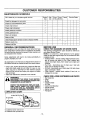
CUSTOMER
MAINTENANCE
RESPONSIBiLITiES
SCHEDULE
Before
Use
Filt in dates as you complete regular service
After
Use
Every
Every
Yearly
Hrs,r 25 Hrs ,,
Service Dates
5
I
Check for damaged or worn parts
v"
Check for loose fasteners & parts
v"
Check chain tension
.....
i
,
Check Chai'n"sharpness
v"
....Ciqeck guide bar condition
v"
v"
Check guide bar lube
Clean unit & labels
Clean air filter
Clean/inspect spark arrestor screen & inspect muffler
Replace spark plug
Replace fuel filter
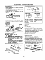
GENERAL
!
'1 .......
BEFORE
RECOMMENDATIONS
The following damaged!worn parts should be referred to
your Sears Service Center,
NOTE: It is normal for a small amount of oil to appear
under the saw after engine stops. Do not confuse this with
a leaking oil tank.
• On/Stop Switch - ensure on/stop switch functions properly by moving the switch to the "Stop" position and
assure that engine stops, then restart your engine and
continue,
• Fuel Tank - discontinue use of chain saw if fuel tank
show signs of damage or leaks_
• Oil Tank - discontinue use of chain saw if oil tank shows
signs of damage or leaks.
• Chain Catcher - replace chain catcher if bent, cut, or
damaged in any way,
Some adjustments will need to be made periodically to
properly maintain your unit.
All adjustments in the "Service and Adjustments" section of
this manual should be checked at least once each season.
. Once a year, replace the spark plug, replace air filter element and check guide bar and chain for wear. A new
spark plug and a clean/new air filter element assures
proper air4uel mixture and helps your engine run better
and last longer.
• Follow the maintenance schedule in this manual
CHECK FOR LOOSE FASTENERS
WARNING:
•
•
•
•
•
•
•
•
•
DISCONNECT THE SPARK PLUG BEFORE
PERFORMING MAINTENANCE EXCEPT FOR
CARBURETOR ADJUSTMENTS,
INSPECTTHE ENTIRE UNIT. REPLACE DAMAGED PARTS. CHECK FOR FUEL LEAKS
AND MAKE SURE ALL FASTENERS ARE IN
PLACE AND SECURELY FASTENED.
CHART
(£ Bar Oil Fill Cap
@ Sprocket
USE
CHECK FOR DAMAGED OR WORN PARTS
The warranty on this unit does not cover items that have
been subjected to operator abuse or negligence° To receive
full value from the warranty, the operator must maintain unit
as instnJctedin this manual
LUBRICATION
....
\
O Craftsman chain saw bar oil
® Craftsman bar sprocket lube
-19-
Bar Clamp Nut
Chain
Muffler
Cylinder Shield
Air Filter
Clutch Drum/Sprocket
Handle Screws
Starter Housing
Handguard
AND PARTS
CUSTOMER
RESPONSIBILITIES
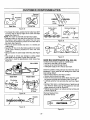
CHAIN TENSION
o Use the screwdriver end of the bar tool to move chain
around the guide bat:
° If chain does not rotate, it is too tight - slightly loosen bar
clamp nuts and turn adjusting screw 1/4 turn counterclockwise+ Retighten bar clamp nuts.
, If chain is too loose, it wilf sag below the guide ban
Figure 29.
Sag
CHAIN CUTTER PART NAMES
Top Plate
Gullet
_--_
'
Depth
Side Plate
't
., "_ _e
Toe --'-_"#" Hole
CHAIN "PITCH"
CHAIN "GAUGE"
\
This distance
divided by two
Thickness of bottom
section of drive link _
Figure 29
• If chain is too loose, refer to "Chain Adjustment." Loosen
bar clamp nuts; then, turn adjusting screw 1/4 turn clock+
wise. Lift up tip of guide bar to check for sag. Retighten
bar clamp nuts
Guide Bar
Pitch refers to chain measurement A chain's pitch
is the distance between
any three of its rivets
divided by two+
Gauge refers to thickness
of that portion of drive link
which fits into saw bar
groove.
Tools required:
o Flat file
- 030 depth gauge
- 4+5mm round file & file holder'
Conditions which indicate the need for chain sharpening:
o Reduction in size of wood chips+The size of the wood
chip wilt decrease as the chain gets duller' until it
becomes more like a powder than a chip. Note that dead
or' rotted wood wilt not produce a good chip.
o Saw cuts to one side or at an angle+
° Saw requires excessive force to cut+
- Noticeable loss of cutting speed.
Bar
Tool
Figure 30
SHARPENING CHAIN
(Fig. 31,32, 33, 34, 35, 36 & 37)
WARNING:
Sharpening instructions:
° Move on/stop switch to the "Stop" position.
• Check chain for proper tension. Adjust chain tension if
necessary. (See Chain Tension/Adjustment)+
• Check and lower depth gauges before sharpening cutters.
° Depth gauges should be checked every third sharpen=
ing. When cutting frozen wood the depth gauges should
be checked each time you sharpen the chain.
• To check depth gauge, place gauge toot on cutter+If the
depth gauge projectsabove the tool, then file it level to
the top of the depth gauge tool.,See Figure 31+
IMPROPER CHAIN SHARPENING TECHNIQUES AND/OR DEPTH GAUGE MAINTENANCE WILL INCREASE THE CHANCE OF
KICKBACK, WHICH CAN RESULT IN SERIOUS INJURY.
ALWAYS WEAR GLOVES WHEN HANDLING
THE CHAIN. THE CHAIN CAN BE SHARP
ENOUGH TO CUT YOU EVEN THOUGH IT IS
TOO DULL TO CUT WOOD.
CHAIN TERMINOLOGY & PART NAMES
Preset Tie Strap
Left Hand CutteF
File
Depth Gauge Tool
+
Ti___
+_ve
Link
Figure 31
Right Hana_-_
_
Cutter
"_k e &
l G"_'ardTie Strap
- 20 -
CUSTOMER
.030"
f====_r_"
RESPONSiBILITiES
Squared
Off Corner
Rounded
Corner
Holder
Figure 35
Wrong Way
Right Way
Cutters Same
Length
Figure 32
. To sharpen the cutters, position the file holder level (90°)
so that it rests on the top edges of the cutter and depth
gauge. See Figure 33
NOTE: The chain has both left and right hand cutters.
- Sharpen cutters on one side of the chain first.,File from
the inside of each cutter to the outside. Then turn your
saw around and repeat the process for the other side of
the chain. See Figure 34.
, File on the forward stroke only..Use 2 or 3 strokes per
cutting edge.
• Keep the 25° line on the file holder parallel to the center
of the chain. Reverse procedure for other side.. See
Figure 35.
° Keep all cutters the same length when filingr See Figure
3&
, File enough to remove any damage to cutting edges
(side plate and top plate) of cutter_See Figure 26.
• File chain to meet the specifications shown below° See
Figure 37.
10°
J-F
Side Plate
/
Top Plate
Figure 36
Figure 37
GUIDE BAR MAINTENANCE
(Fig. 38 & 39)
Conditions which require guide bar maintenance:
* saw cuts to one side or at an angle.
. saw has to be forced through the cut.
• inadequate supply of oil to the bar and chain,
FULL VIEW
SIDE VIEW
Remove Damage
Check the condition of the guide bar each time the chain is
sharpened. A worn guide bar will damage the chain and
make cutting difficult..
• Move on/stop switch to the "Stop" position_
• Remove bar and chain from saw°
° Clean all saw dust and any other debris from the guide
bar groove and guide bar lubrication hole.. Figure 38.
° Lubricate guide bar hole sprocket after each use. Figure
38.
• Burring of bar rails is a normal process of guide bar rail
wear. Remove these burrs by filing guide bar rail side
edges square with a flat file_Figure 39.
• Restore square edges to an uneven rail top by filing with
a flat file. Figure 394
FRONT VIEW
File Holde_
/
File
Cutter O
Depth Gauge
& Chain
Remove Sawdust From
Figure 33
Outside
Guide Bar Groove
__et
tnside _
Figure 34
Figure 38
- 21 -
Hole
CUSTOMER
RESPONSIBILITIES
Replace the guide bar when:
. the inside groove of the guide bar rails is worn.
• the guide bar is bent or cracked
- excess heating or burring of the rails is noted°
_.,=_
/_
If replacement is necessary, use only the replacement
reduced kickback guide bar specified for your saw in the
repair parts list or as specified on the replacement bar and
chain decal located on the chain saw_
_-,,=
Correct
Groove
Worn Grooves
File _==-_
I_
Air Filter Cover
Retainer Screw
Air Filter
,Screw
Air Filter
Cover
File Edges
Square
Figure 40
Figure 39
EVERY 25 HOURS
INSPECT MUFFLER AND SPARK ARRESTOR
SCREEN (IF INSTALLED) (Fig. 41)
AFTER USE
CLEAN UNIT AND LABELS
= Clean the unit using a damp cloth with a mild detergent
after use.
° Wipe off the unit with a clean dry cloth..
As the unit is used, carbon deposits build up on the muffler
and spark arrestor screen (if installed), and must be
removed to avoid creating a fire hazard or affecting engine
performance.
EVERY
Required cleaning is every 25 hours of operation or' annually, whichever is less,
5 HOURS
CLEAN AIR FILTER (Fig. 40)
A dirty air' filter decreases the life and performance of the
engine and increases fuel consumption and hamrful emissions.
Always clean your air filter after 25 tanks of fuel or 5 hours
of operation, whichever is less. Clean more frequently in
dusty conditions.. A used air filter can never be completely
cleaned.. It is advisable to replace your' air filter with a new
one after every 50 hours of operation, or annually, whichever is tess,
•
.
•
°
•
Loosen the air filter cover retainer screw.
Remove air filter cover,.
Loosen the air' fiiter screw and the two air fitter retainers.
Remove the air filter
Use a stiff nylon bristle brush to clean the air filter in hot
soapy water_ Rinse with clean cool water, and air dry
completely prior to reinstalling.
• Reinstall air filter and tighten air filter screw and air filter
retainers°
o Reinstall air' filter' cover and tighten air filter cover retainer screw.. (15-20 in-lb).
Replace the spark arrestor screen if breaks occur°
CLEANING THE SPARK ARRESTOR SCREEN
- Loosen and remove the 2 mufflercovet screws=
, Remove the muffler cover (cover snaps into muffler
body),
° Remove muffler diffuser and spark arrestor screen
assembly. Notice the orientation of these parts for
reassembiy,
° Clean the spark arrestor screen with a wire brush or
replace if breaks are found in the screen..
-Repiace any broken or cracked parts..
° Reinstall diffuser and spark arrestor screen assembly
with round holes facing up and towards muffler cover.
Reinstall muffler cover and 2 screws (7_8 ft4bs)_
Muffler
Cover
Screws
Muffler
Cover
\
Muffler Diffuser/
Spark Arrestor
Screen
Figure 41
- 22 -
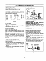
CUSTOMER RESPONSIBaLITIES
YEARLY
IFuel Cap
IRetainer
REPLACE
SPARK PLUG (Fig. 42)
The spark plug should be replaced each year to ensurethe
engine starts easier and runs better. Spark plug gap
should be .025".
= Loosen and remove 4 screws on cylinder cove[.
- Remove cylinder cover.
• Twist, then pull off the spark plug boot.
• Remove spark plug from cylinder and discard.
• Replace with correct spark plug and tighten with a 3/4"
socket wrench (10-12 ft-tb)..
• Reinstall spark plug boot.
o Reinstall cylinder cover and 4 screws (35-40 in-tb).r
Fuel Mix
Fill Cap
Figure 43
Cylinder
Cover
Screws
Plug Spark
v
Figure 42
REPLACE
Figure 44
FUEL FILTER (Fig. 43, 44 & 45)
The fuel filter shouid be replaced after each season Never
operate your saw without a fuel filter Be careful not to
damage fuel line while removing the fuel filter.
° Run fuel tank dry of fuel before proceeding with this step.
, Remove fuel cap and allow it to hang to side of motor.
° Using a small pair of needle nose pliers, grasp fuel cap
retainer, holding it in tank opening and pull out.
,, With cap out of tank, use a small section of bent wire
similar to that shown in the illustration to catch fuel fine
and slowly pull from tank_ When fuel filter appears in
opening, grasp with fingers and remove from tank.
• Once filter is out of tank, hold fuel line close to fuel filter..
Remove fuel filter by twisting and pulling at the same
time.
• Replace fuel filter,
• Reverse process for installation.
- 23 -
Fuel Line
/'__--_'f__
Fuel Filter
Barrel
Fuel Filter
_,_
j_
Filter Neck
Figure 45
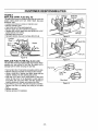
SERVICE
AND ADJUSTMENTS
CHAIN REPLACEMENT
Now proceed to the "Chain Adjustment"section,
(Fig. 46, 47, 48 & 49)
CAUTION: Wear protective gloves when handling chain.The chain is sharp and can cut you
even when it is not moving.
It is normal for a new chain to stretch.Because
of this initial stretch during the first 15-30
minutes of operation you should recheck your
chain tension frequently and adjust the chain
tension as required. See chain tension section.
Bar Clamp
Nuts
o Move on/stop switch to the "Stop" position,
- Replace the old chain when it becomes worn or damaged.
• Use only the Low-Kickback replacement chain specified
in the repair parts list or as specified on the replacement
bar and chain decal located on the chain saw,
• See your Sears Service Center to replace and sharpen
individual cutters for matching your chain.
. Loosen and remove the 2 bar clamp nuts,,
= Remove bar clamp.
• Remove the old chain.
Figure 49
CHAIN ADJUSTMENT
(Fig. 50, 51, 52 & 53)
Roll chain around guide bar to ensure kinks do not exist
(rotates freely),
° Assure bar clamp nuts are loosened (fingertight),
• Turn adjusting screw clockwise untit chain just barely
touches the bottom of guide bar,,
o Roll chain aroundguide bar to ensure all links are in bar
groove,
AdjustingScrew
pin justscrew
touches
stop.
i adjusting
urn adjusting
by the
hand
counterclockwiseuntil
Carefutly remove new chain from package,,Hold chain
with the drive links as shown in Figure 47,
Place chain over and behind the clutch.
Fit bottom of drive links between teeth in sprocketnose.
Fit chain drive links into top of guide bar. Figure47.
Bar Tool
Figure 50
• Lift up tip of guide bar to check for sag, release tip of
guide bar', then turn adjusting screw t/4 turn clockwise..
Repeat this step until a sag does not exist.
° While liftingtip of guide bar; tighten bar clamp nuts with
the bar tool (provided).Torque 10-15 lt-tbs.
_,djustingScrew
.'_-- _
.,'_ t_
Bar Clamp
Figure 46
®
,,,To,°j j..
I
,_" Cutters
__" Depth Gauge
1
Figure 51
To check chain tension
° Use the screwdriver end of the bar tool to move chain
around the guide bar (Figure 53),
° if chain does not rotate, it is too tight - slightly loosen bar
clamp nuts and turn adjusting screw 1/4 turn counterclockwise, Retighten bar clamp nuts,
• If chain is too loose, it will sag below the guide bar
(Figure 52).
Guide Bar
Lower Hole
Gu,dBar
l
Figure 47
• Move guide bar fonNard by turning the adjusting screw
clockwise untit chain is snug in guide bar grooves°
° Now instalt bar clamp,
,_ _
JhY'
Sag
Guide Bar
Mounting Botts
Figure 48
• Install bar clamp nuts and finger tighten only. Do not
tighten any further at this point.
- 24 -
Figure 52
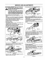
SERVICE AND ADJ USTM ENTS
• If chain is too loose, refer to "Chain Adjustment? Loosen
bar clamp nuts; then, turn adjusting screw 1/4 turn clockwise, Lift up tip of guide bar to check for sag.,Retighten
bar clamp nuts.
Pultey
•Screw
Starter
Rope
Handle
Bar
Tool
Guide
Bar
t I_ulley
--..-----"
Adjusting
Screw
,/Ratchet
Figure 55
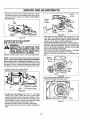
• Move away from the fuel tank and melt the end of the
new rope to be installed. Allow the melted end to drop
once.Then, while the rope is still hot, pull the melted end
through a rag to obtain a smooth pointed end,
° Feed rope through starter rope hote in starter housing,
• Guide the rope inside the pulley, then up through the pulley hole, It may be necessary to push the rope through
with a small Phillips screwdriver inserted into the small
hole on the underside of the pulley.
• Form a knot in the end of the rope leaving a 1"tail, Make
sure knot is tight, then cut about 1/2 of tail off,
• Rewind all the rope onto the pulley in a clockwise direction.
Figure 53
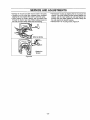
STARTER ROPE REPLACEMENT
(Fig. 54, 55, 56, 57 & 58)
WARNING:
ALWAYS WEAR EYE PROTECTION WHEN
SERVICING THE STARTER ROPE. THE
RECOIL SPRING BENEATH THE PULLEY IS
UNDER TENSION, IF THE SPRING POPS
OUT, SERIOUS INJURY CAN RESULT.
Replace a broken starter rope or one that is badly frayed
NOTE: A recoil spring lies beneath the pulley and is under
tension. If the recoil spring is disturbed, considerable
time and effort will be required to reinstall. Forthis reason you may want to let your Sears Service Center handle
this repair,,If you try to repair the starter rope and the recoil
spring pops out, take the unit to your Sears Service Center.
Housin{
• Remove the four fan housing screws,
. Remove fan housing from the unit,
Rope
Hoie
Notch
Figure 56
• Twist and push pulley into starter housing_
• Replace and tighten the pulley screw.
/
/
..4----
Starter Rope Pulley
(inside Fan Housing)
Pulley
Fan Housing Screw
Figure 54
• To take out rope tension, pull out 10" of rope, While
holding down pulley ratchet with thumb, push several
inches of rope back into fan housing and catch in notch,
Either hold pulley ratchet with thumbor hold starter rope
handte, Retain rope in the notch and slowly allow pulley
to turn counterclockwise until tension is gone.
• Remove the pulley screw in the center of the pulley,
•Gentty twist and lift pulley while rotating counterclockwiser
- 25 °
Screw
Pulley
Figure 57
SERVICE AND ADJUSTMENTS
- Pull out 10" of rope and catch rope in notch in the pulley
• Carefully turn the pulley two complete turns clockwise,
keeping the rope against the notch to wind the spring.
o While holding the pulley ratchet, pull the excess rope
through the starter rope hote. While holding tension on
the rope, let rope slowly rewind into the housing
Wind Up Spring
Figure 58
- 26 -
- Reinstall fan housing by aligning the fan housing to the
chassis_ Then while holding the fan housing againstthe
chassis, pull the rope handle out until you feel the fan
housing drop into place against the chassis. Stcwly', le:t
the rope rewind into starter housing.
• Reinstall the 4 fan housing screws. Figure 54.
SERVICE AND ADJUSTMENTS
CARBURETOR
ADJUSTMENTS
Carburetor adjustment is critical and if done improperly can permanently damage the engine as well as the
carburetor. Please read all instructions and consult the
Trouble Shooting section of this manual before beginning this process° If the engine does not operate
according to these instructions after repeating the
adjusting steps, do not use the unit. For further assistance, please call our customer assistance hotline at
1-800-235=5878_
WARNING:
THE CHAIN WILL BE MOVING DURING
MOST OF THIS PROCEDURE. WEAR YOUR
PROTECTIVE EQUIPMENT AND OBSERVE
ALL SAFETY PRECAUTIONS.
IN"LOW SPEED MIXTURE ADJUSTMENT,"
RECHECK
IDLE SPEED AFTER EACH
ADJUSTMEN% THE CHAIN MUST NOT
MOVE ATIDLESPEED.
If engine does not start, it may be flooded° If in doubt, read
the section on flooded engine in the starting section of this
manual prior to beginning any adjustments.
The carburetor has been adjusted at the factory for sea
level conditions,,Adjustments may become necessary if the
saw is used at significantly higher altitudes or if you notice
any of the following conditions:
CARBURETOR
PRESETS
(Fig. 59)
If your engine will not start due to suspected improper carburetor adjustment, the following presets may be required,
If used, it is recommended that all steps within the adjustment procedure be completed in order to assure a properly
set carburetor,, If presets are not needed, proceed to section "ldte Speed AdjustmenU'
Very smatl adjustmentscan affect engine performance. It is
important to make slight adjustments and test performance
before proceeding. Each adjustment should be no more
than 1/16 of a turn,
• Turn both of the mixture adjustments clockwise until
they stop. Do not overtighten as damage to the needle
seats will occur
• Turn both mixture adjustments counterclockwiseone full
turn_
, Turn the idle speed adjustment clockwise until it stops_
Now turn counterclockwise 4-1/2 turns,
• If engine fails to start after performing carburetor presets,
the unit may be flooded° Review the "Difficuft Starting"
section of the manual, tf problems, continue, call the
1-800 number listed on the front cover of this manual for
further assistance.
= Start the engine and operate for three (3) minutes to
warm upoGo to "Adjusting Procedure?
High Speed
Mixture
Adjustment
/
Idle Speed Adjustment
° Chain moves when the engine runs at idle speed. See
"Idle Speed Adjustment."
= Saw will not idle See "Idle Speed Adjustment" and "Low
Speed Mixture AdjustmenV'
- Engine dies or hesitates when it should accelerate° See
"Acceleration AdjustmenU'
• Loss of cutting power which is not corrected by air filter
cleaning. See "High Speed Mixture Adjustment,"
Mixture
Adjustment
NOTE=There are three adjustments on the carburetor,,
= The Idle Speed Adjustment is marked with the letter "1"."
• The two remaining adjustments on the carburetor are the
mixture adjustments. One is marked "L_'for low speed,
and the other "H"for high speed°
Figure
27 -
59
SERVICE AND ADJUSTMENTS
HIGH SPEED MIXTURE ADJUSTMENT "H"
IMPORTANT: DO NOT OPERATE ENGINE AT FULL
THROTI'LE FOR PROLONGED PERIODS WHILE MAKING HIGH SPEED ADJUSTMENTS AS DAMAGE TO THE
ENGINE CAN OCCUR,,
ADJUSTING
PROCEDURE
IDLE SPEED ADJUSTMENT "T"
• Allow the warm engine to idle._
• Adjust the Idle Speed until the engine continues to run
without stalling and without the chain moving.,
- Turn clockwise to increase engine speed if engine
stalls or dies.
- Turn counterclockwise to slow engine down and/or to
keep the chain from turning.
• No furlher adjustments are necessary if chain does not
move at idle speed and if performance is satisfactory..
o Make a test cut°
° Based on performance of the saw while cutting, adjust
the high speed mixture in 1/16 turn increments as fol,
lows:
- Clockwise if saw loses power in the cut, Do not adjust
for best power by sound or speed, but judge by how
well the saw performs in the cut.
- Counterclockwise if the saw has speed while out of the
cut, but dies in the cut ot lacks power while cutting_
• Repeat the test cut.
• Continue with t/16 turn adjustments until the saw performance is acceptable while cutting,_
= After completing adjustments, check for acceleration.
LOW SPEED MIXTURE ADJUSTMENT "U'
• Allow engine to idle.
° Turn the Low Speed Mixture Adjustment slowly clockwise until the RPM starts to drop,,Note the position_
• Turn the Low Speed Mixture Adjustment slowly counterclockwise untit the RPM speeds up and starts to drop
again. Note the position.
• Set the Low Speed Mixture at the midpoint between the
two positions,.
ACCELERATION CHECK
• If the engine dies or hesitates instead of accelerating,
turn the Low Speed Mixture Adjustment 1/16 of a turn at
a time counterclockwiseuntilyou have smooth acceletm
tiono
• Check the idle speed for stability and no chain movemenL Adjust as necessary.
o Recheck for smooth acceleration and stable idle. Repeat
process as necessary for acceptable performances
28 -
STORAGE
Immediately prepare your unit for storage at the end of the
season or if it will not be used for 30 days or more
IMPORTANT: it is important to prevent gum deposits from
forming in essentialfuel system parts such as the carburetor,fuel filter,fuel hose or tank during storage.. Also, experience indicatesthat alcohol blended fuels, those that use
ethanol or methanol (called gasohol or oxygenated fuel),
canattract moistureand form acidic gas which will damage
your engine°To avoid engine problems, the fuel system
should be emptiedbefore storage of 30 days or longer.
WARNING:
ALLOWTHE ENGINETO COOL, AND SECURE
THE UNIT BEFORE STORING OR TRANSPORTING IN A VEHICLE.
STORE UNIT AND FUEL IN AN AREAWHERE
FUEL VAPORS CANNOT REACH SPARKS OR
OPEN FLAMES FROM WATER HEATERS,
ELECTRIC MOTORS OR SWITCHES, FURNACES, ETC.
Fuel stabilizer is an acceptable alternative in minimizing
the formation of fuel gum deposits during storage. Add stabilizer to the gasoline in the fuel tank or fuel storage container. Always follow the mix instructionsfound on stabilizer
containers. Run engine at least 5 minutes after adding stabilizer to allow the stabilizer to reach the carburetor°
STORE UNIT WITH ALL GUARDS IN PLACE.
POSITION SO THAT ANY SHARP OBJECT
CANNOT ACCIDENTALLY CAUSE INJURY TO
PASSERS BYo
CRAFTSMAN 40:1 2-cycle engine oil (AIR-COOLED) is
specially blended with fuel stabilizer.r If you do not use this
Sears oil, you can add a fuel stabilizer to your fuel tank.
STORE THE UNIT OUT OF THE REACH OF
CHILDREN.
INTERNAL
ENGINE
WEAR
PROTECTIVE
GLOVES
WHEN
•
Remove
spark
plug and pour I teaspoon of 40:1 2_cycle
HANDLING CHAIN. THE CHAIN IS SHARP
engine oil (AIR-COOLED) through the spark plug openAND CAN CUT YOU EVEN WHEN IT IS NOT
ing_Slowly pull the starter rope 8 to 10 times to distribute
MOVING.
,..........................
j
oil to inner engine surfaces.
• Replace spark plug with a new one of the recommended
GAS CHAIN SAW STORAGE INSTRUCTIONS
type and heat range. Refer to "Product Specifications°"
If your chain is to be stored for a period of time, clean it
• Ctean air filter. Refer to "Customer Responsibilities_"
thoroughly prior to storage. Remove any dirt, sawdust,
• Re-install all covers and hardware removed for access;
Ieaves, oil, grease, etcoStore in a clean dry area°
tighten all screws and fasteners.
• Clean the entire unit.
= Check entire unit for loose screws, nuts, and bolts.
•CIean air filter. Refer to "Customer Responsibilities?
Replace any damaged, broken, or worn parts.
• Inspect the bar clamp area and clean any dirt, sawdust,
• t.ightly oif external meta! surface to prevent rust from
grass, or debris that has collected. Inspect the guide bar
forming,.
and chain; replace a guide bar that is bent, warped,
• Use fresh fuel having the proper gasoline to oil ratio at
cracked, broken, or damaged in any other way. Replace
the beginning of the next season,
a damaged or worn chain.
= Lightly oil external metal surfaces to prevent rust from
OTHER
forming.
• Do not store gasoline from one season to another,
• Apply a coating of oil to the entire surface of the guide
• Replace your gasoline can if your can starts to rust. Rust
bar and chain; wrap it in heavy paper or cloth.
and/or dirt in your fuel system will cause problems.
° Be sure all handles and guards are in place and are
, Store your unit in a wel! ventilated area and covered, if
securely fastened. Replace any damaged parts.
possible, to prevent dust and dirt accumulation. Do not
cover with plastic, Plastic cannot breathe and will induce
condensation and eventual rust or corrosion.
FUEL SYSTEM
Never use engine or carburetor cleaner products in the fuel
tank or permanent damage may occur to fuel system components. Follow these instructions:
• Drain the fuel from the unit into an approved fuel container
• Drain the fuel lines and carburetor by starting the engine
and letting it run until it stops.
° Allow the engine to cool before storage.
IMPORTANT: NEVER COVER UNIT WHILE
AND EXHAUST AREAS ARE STILL WARM.
- 29 -
ENGINE
TROUBLE
TROUBLE
SHOOTING
SHOOTING
CHART
SYMPTOM
CAUSE
Engine will not start or
will only run only for a
few seconds after
starting.
1._Fuel tank empty.
2_ Engine flooded.
3. Spark plug not firing.
4. Fuel not reaching carburetor.
5 Carburetor requires adjustment.
6 Stop switch off..
7. None of the above.
Engine will not idle
properly
1. Idle speed set too fast or' too SLOW.
2 Low speed mixture requires adjustmenL
3. Crankshaft seals worn.
4 Compression low.
5. None of the above.
Engine will not
accelerate, lacks
power, or dies
under a load
Engine smokes
excessively.
I.
2.
3.
4.
5.
6.
7.
Oil inadequate for bar
and chain lubrication.
1
2.
3.
4.
Chain moves at idle
speed.
Chain does not move
when engine is
accelerated,
1. Idle speed requires adjustment.
2. Clutch requires repair.
Chain stops within the
out.
Chain cuts at an angle.
CORRECTION
t Fill tank with correct fuel mixture,
2. See "Starting Instructions`"
3. Install new plug/check ignition system.
4,. Replace fuel filter; inspect fuel line.
5. See "Carburetor Adjustments."
6. Move switch to the "Or]" position
7. Contact your' Sears Service CentedDept.
t ,. See "Carburetor Adjustments,."
2. See "Carburetor Adjustments."
3. Contact your' Sears Service CentedDept,
4. Contact your Sears Service CentedDept,
....5, Contact your Sears Service CentedDept.
1. Air filter dirty.
1. Clean or replace air filter:
2. Spark plug fouled.
2, Clean or' replace spark plug and re-gap.
& Carburetor requires adjustment.,
3. See "Carburetor Adjustments."
4 Exhaust ports or muffler outletsplugged_ 4. Contact your Sears Service CentedDepL
5. Compression low.
5.. Contact your Sears Service CentedDepL
6. None of the above.
6. Contact your Sears Service CenterlDept.
1. Air filter dirty.
1 Clean or replace air filter.
2 Refuel with correct fuel mixture°
2. Fuel mixture incorrect_
3. High speed mixture requires adjustment.
3. See "Carburetor Adjustments."
4 Push blue choke knob in.
4.. Choke partially on.
5. Crankcase leak.
5. Contact your Sears Service Center/Dept,
Engine runs hot°
Chain clatters or cuts
roughly.
POINTS
Fuel mixture incorrect.
High speed mixture set too low (lean).
Spark plug incorrect_
Exhaust ports or muffler outlets plugged.
Carbon build-up on muffler outlet screen°
Fan housing/cylinder fins dirty..
None of the above.
..........
Oil tank empty.
Oil pump or oil filter clogged.
Guide bar oil hole blocked.
Oiler out of adjustment.
I. Chain tension too tighL
2. Carburetor requires adjustment.
3. Guide bar rails pinched.
4, Clutch slipping.
1. Chain tension incorrecL
2, Cutters damaged
3. Chain worn.
4. Cutters dull, improperly sharpened, or
depth gauges too high.
5. Sprocket worn.
6. Chain installed backwards.
1, Chain cutter tops not filed flat.
2. Guide bar' burred or bent; rails uneven.
3, Clutch slipping.
'"io Cutters damaged on one side,
2. Chain dull on one side,
3. Guide bar' bent or worn.
1 See "Fueling Your Unit."
2. See "Carburetor Adjustments_"
3. Replace with correct plug,
4. Contact your Sears Service CentedDepL
& Clean spark atrester screen.
6 Clean are&
7' Con tact your Sears Service CenterlDept.
1. Fill oi! tank,
2. Contact your Sears Service Center/Depto
3. Remove bar and cleam
4. See "Operation" Section.
t. See "Carburetor Adjustments,"
2. Contact your Sears Service Center/Dept.
1. See "Chain Tension."
2, See "Carburetor Adjustments:'
3. Repair or' replace.
4, Contact your Sears Service Center/Dept.
1. See "Chain Tensions"
2. Contact your Sears Service CentedDept.
3. Resharpen or replace chain.
4. See the chain sharpening instructions.
5. Contact your Sears Service CentedDepto
6. Install chain in right direction.
1. See the chain sharpening instructions°
2 Repair or replace guide bar:
3. Contact your Sears Service CentedDept.
!. See the chain sharpening instructions.
2. See the chain sharpening instructions..
3. Replace guide bar,
If situations occur which are not covered in this manual, use care and go,d judgement.
If you need assistance, contact your SEARS Service Center/Department or the
CUSTOMER ASSISTANCE HOTLtNE at 1-800..235-587&
30 -