1
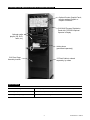
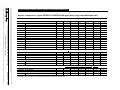
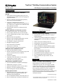
TrueCom™ Building Communications System UL, cUL Listed* 5120 Series Communications Controllers General Features 5120 Series Communications Controllers provide: Audio control center integration with an open voice controlled intercom capable of multi-zone paging and program distribution Extensive capabilities and programming flexibility allow facility customized operation 5120 Series Communications Systems are configurable for either structured wiring (typically for new construction) or traditional twisted/shielded audio cable (typically for retrofit) Network-Ready architecture for Enterprise-Wide applications System capabilities and intercom overview: 360 Station point capacity with 72 Paging zones Privacy and pre-announce tones are user selectable 15 Voice amplified intercom links w/AGC (automatic gain control) Enhanced Caller ID compatibility Emergency All-Call paging and Automatic All-Call Emergency with voice ID Announcement User definable, emergency function keys Designated emergency phone Direct architectural room dialing Security device monitoring Wall rack mounting (rack supplied separately) Additional audio capabilities include: Solid state audio program switching Network connectivity to remote locations using VOIP (Voice over Internet Protocol) on Ethernet infrastructure Conference capability Compatible with 45 ohm and/or 25 volt speakers; station speakers are direct coupled Compatible with existing phone systems Administrator capabilities include: Up to four administrative telephones with displays Administrative emergency override Automatic administrative transfer via time control Emergency “All Call” microphone input Front end integration with telecommunications System options include: Integrated master clock, 72 output graphic control boards, 72 input/output graphic I/O boards, and additional 24 port paging boards Pre-recorded media controllers (CD, DVD, radio, etc.) RJ-45 10/100 Ethernet LAN Drops for VOIP devices 5120 Card Cage Assembly Programming Features Extensive programming flexibility: Programmable via phone or Microsoft® Windows® based programmer “Off-Site” programming and diagnostic capability via optional modem or LAN (EIA RS-232 or 10 BaseT LAN Port) Ethernet based System Management Tool Programmable voice announced call identification Custom digitized announcements Three (3) simultaneous audio distribution program channels and eight (8) programmable class change tone schedules Eight (8) programmable control relays Seven (7) programmable call priorities Programmable automatic Daylight Savings Time Six (6) programmable monitor point inputs Nine (9) available tones plus custom .wav tone capabilities Description Simplex® 5120-9000 series equipment incorporates the latest innovations in electronic technology to offer a high performance, microprocessor controlled communication system. The 5120 integrates an audio control center with an open voice controlled intercom capable of multi-zone paging and program distribution. By incorporating solid state electronic switching in its design, mechanical breakdown has been virtually eliminated. The system has the flexibility to fulfill a broad scope of communication needs in both industrial and institutional facilities. (continued next page) * Power supply Model 5120-9174 is UL listed and certified by UL for Canada. Refer to data sheet S5120-0055 for additional power supply details. S5120-0012-17 3/2010 Description (Continued) Speed Dialing. Since these ports accept standard telephones using DTMF tone type dialing, phones with speed dial capability can be utilized to keep functions such as paging specific areas, transferring calls or activating emergency tones literally one touch away. Since each phone is programmed individually, each can have its own set of speed dial buttons for its most frequently used functions. Modular Design. 5120 Series systems are modular in design allowing for easy expansion and servicing of the equipment. System components are mounted in an EIA standard 19” wall/floor rack. Punch blocks, cables, and AC power connections are conveniently located within the rack and are hidden from view. The total system capacity of 360 points (stations) can be reached by the installation of up to 15 communication modules. Stations can be assigned 2, 3, or 4 digit numbers. Synthesized Speech Caller ID. The 5120 uses a synthesized speech circuit to provide Caller Identification within the system. When a call is answered at the Administrator’s Phone or through an existing phone system, the 5120 announces the caller’s room number and automatically connects the calling party. This feature eliminates the need for the traditional display phone used solely for call annunciation. Digitally Programmed Announcements. Each 5100 CPU is provided with a voice chip providing the facility with their choice of a male or female voice for automatic announcements. In addition, four (4) minutes of spare memory is accessible for custom messaging with the desired voice, accent, or language. The ability to add custom tones is also provided to meet the needs of particular facilities. An easy-to-use Windows tool is provided to edit or record custom tones and phrases. Easy Interface. The 5120 is designed to directly interface with conventional in-house phone systems through four (4) Loop Start Trunk Ports. This direct integration allows most existing phone systems to access and control the communications system without the need for costly interface modules. The 5120 phones can access the in-house system in a similar manner and outside lines connected to it, if allowed, via its CPU programming. In addition, a call from the users phone system may be forwarded into the 5120 system and conferenced between Administrative Phones. Administrative Phone Operation. The 5130-9140 series of PC boards are used to support up to 24 stations requiring speaker and call switch capabilities. These stations may be programmed to ring a specific Administrative Phone in the system. During the night, these calls can be programmed to ring a different phone and automatically return to the original phone in the morning. This transfer can also be initiated manually if required. A call may be transferred to another Administrative Phone or a conference can be set up. The administrative ports can be designated as an emergency station and receive emergency calls. Flexible Intercom Programming. Each of the 360 intercom stations call switches can be programmed for one of seven (7) priority levels. This allows calls from specified areas to take precedence over other calls. For example: a typical classroom might be specified as a normal priority, the gymnasium urgent priority, and the nurse’s office emergency. In the event the administrative stations are busy handling calls, high priority calls cause the person using the Administrative Phone to hear a distinct signal indicating a priority call is waiting. Emergency calls will automatically move to the top of the queue, followed by urgent calls. (continued on page 4) Central or Distributed. The system is designed to be installed in a single central console or to be distributed in up to 16 separate locations for multiple building campuses. All inter-panel connections are Ethernet based using Voice over IP technology. PC Based Control. The 5120 system may be controlled via a Windows based PC directly connected to the system or over a network. This simple to use, point and click tool allows administration to easily facilitate common tasks such as distributing music, adjusting time schedules or activating emergency tones to name a few. Drop down windows provides the user an easy-to-follow format. Administration Display. A prompting 4 x 20 character LCD backlit display (5130-9253/9254) is also available for administrative purposes. When not being used for programming, the 5130-9253 displays the time, day, and date as well as the current operating master time schedules. Up to three incoming calls can be displayed, as well as how many additional calls beyond three are on hold in the calling queue. Operation Details Multiple Schedules and Programs. Eight programmable time schedules are available with up to 1,024 events per day for class or shift change time tones. Any one of the nine system tones or custom .wav files can be distributed to any station at any time. Schedules can be run simultaneously allowing maximum flexibility. Audio program distribution and automatic digitized paging announcements can be controlled automatically from these schedules if required. Simultaneous Audio Programs. The system is capable of distributing three audio program sources simultaneously. Any source may be routed to any of the 360 speaker circuits. Solid state switching allows distribution of audio programs from multiple locations equipped with telephones. Priority Selection. Each of the four (4) Administrative Phone ports are assigned one of three priority levels. These priority levels establish access to different system features such as manual control of relays or call bumping (interrupting a conversation in process). 2 S5120-0012-17 3/2010 5120 Series Rack Mounted Controller Equipment Reference Optional Custom Graphic Panel; requires optional Graphic or Graphic I/O Boards 5120-9180 Program Distribution Panel with 5130-9254 Optional Operator’s Display Optional media players (CD, DVD, radio, etc.) Admin phone (purchased separately) 5120 Card Cage Assembly location 19" Rack Cabinet, ordered separately, by others Specifications 5120-9113 Card Cage Dimensions 11-3/4” H (7RU) X 19” W X 13-3/4 D (298 mm x 483 mm x 349 mm) Operating Temperature 32° C to 100° F (0° C to 38° C) Operating Humidity Range Up to 85%, non-condensing 3 S5120-0012-17 3/2010 Operation Details (Continued) Security Monitoring. Each station call-in circuit may be connected to auxiliary security break glass detectors or motion detectors during times when the building is unoccupied. The transfer from conventional intercom operation to security monitoring is accomplished through the system’s internal clock and is programmed locally. One of the eight auxiliary relays would be used to interface with a premise security panel. Station specific amplifiers provide flexibility. Each station is coupled directly to its own amplifier that can access any one of eight internal communication paths. The flexibility of this design allows multiple pages, time tones and intercom or telephone conversations simultaneously. Incoming sensitivity and outgoing gain of the intercom amplifiers are adjustable to compensate for varying field conditions. This design also incorporates Automatic Gain Control (AGC) as well as short circuit protection that increases system reliability and assures sufficient power for All-Call operations. The system is designed to use 45-ohm speakers, 25-Volt speakers, or combinations of both. Programmable Inputs. Six (6) multi-purpose programmable inputs are provided to allow switch closures or relay outputs from other equipment to activate functions within the system. Auxiliary Relay Operation. 5120 systems are equipped with eight auxiliary relays. These relays can be programmed to respond to various happenings within the system such as the security functions described above. An unanswered emergency call can activate a relay that in turn operates a telephone dialer to request assistance. Relays may also be used for door control in conjunction with an intercom station. Intercom Emergency Calls. Emergency calls can be placed via Call Button and begin a unique ringing sequence at the appropriate Administrative Phone. In the event that the call goes unanswered, the system can be programmed to automatically announce, via a synthesized voice, the origin of the call (room number) over a group of speakers or all speakers within the facility assuring a response from a nearby location. Reset occurs when an Administrative Phone answers the call. Please Note: 5120 system auxiliary relays cannot be programmed to ring 120 VAC bells directly, use auxiliary relays for 120 VAC control. Microphone Input. The CPU board has provisions for a directly connected microphone (150-ohm input) for normal All-Call announcements, bus loading, and emergency override paging. Emergency Functions. Function keys on the Administrative Phones may be programmed for single touch emergency functions. Function key #1 can be programmed to cause a warble tone to be transmitted throughout the facility to warn of a tornado alert. A second function key can be used for a manual class change using a 700 Hz tone. The chime tone could be programmed on function key #3 for an All Clear signal. Other typical uses are program distribution or manual activation of night mode. Multiple Tone Selection. The 5120 system is equipped with nine different tones for specific user configurations. Each tone may be field specified for each system function. Tone selection includes: Clock Control. System relays can be used to control clocks requiring standard sync-wired 12-hour correction as well as 24 VDC Digital Clocks requiring 12-hour correction, without the need of an additional Master Clock module. The addition of slave relays with contact ratings suited for the clocks being corrected is required. 5130-9165 Master Clock Option. In the event that non-audio devices (like electro-mechanical bells) are included on time tone schedules, the 5130-9165 master clock option is used. See the description of the master clock assembly under Optional Equipment. Zone Paging. Any of the system’s 360 speaker circuits may be assigned to any or all of the system’s 72 paging zone groups. Zone paging is easily accomplished by entering a three-digit code on a system telephone that has the proper priority level. Two different priority paging levels are available to ensure critical pages are heard in the proper areas. 600 Hz, 650 Hz, 700 Hz, and 1250 Hz Hi-Low (700 Hz - 400 Hz), or Warble Single Chime High (1250 Hz) or Single Chime Low (700 Hz) Internal Clock. The internal system clock can be programmed to automatically adjust for seasonal time changes as well as scheduled class changes. The user is prompted to input the days of daylight savings and the clock is automatically adjusted on the days selected. Dual Chime (1250 Hz/700 Hz) Privacy and Pre-Announce Tones. Privacy tones are generated at the called intercom location to advise the remote location they are being monitored. Pre-announce tones are generated at the beginning of the intercom and paging functions to advise of upcoming message transmissions. (continued next page) 4 S5120-0012-17 3/2010 Operation Details (Continued) Systems Integration Software Diagnostics. 5120 systems are equipped with a built-in software diagnostic program that, upon power up, determines if any troubles are present in the system and informs the user. Should a trouble condition occur during normal operation, LEDs on the CPU or communication boards with the trouble condition advise the operator. The 5120 is easily integrated with premise Key and PBX telephone systems. When integrated with select PBX systems, the following features are available: Battery Backup. Since the 5120 operates on the 5120-9174, 6 A, 24VDC power supply, the system can remain operable when commercial power fails by using an optional uninterruptible power supply (UPS) consisting of a 5120-9175 with 5120-9172 battery set. When this option is ordered, (1) UPS is required per system power supply. (Refer to data sheet S5120-0055 for additional information.) Caller ID trunk integration* Access to intercom and paging functions through PBX phones Universal night ring Override paging Emergency tone activation Clock synchronization * Caller ID information can be passed from the 5120 intercom system through most PBX phone systems via their Caller ID trunk ports and to an administrative phone equipped with a display. This is especially useful during emergency call-in situations, as the exact caller location will be displayed. Built-In RS-232 and 10 BaseT LAN Ports. Each 5120 is equipped with EIA RS-232 and 10 BaseT LAN ports that can be utilized for many functions. Both ports allow full field programmability through a Windows based programmer. Optional Equipment 5130-9165 Master Clock. The 5130-9165 Master Clock Assembly can be directly integrated into the system for correcting clocks and automatically controlling the eight (8) internal relays. Cycling of any one, or all relays during user programmable time periods is available. This option also provides a printer port for Station Message Detail Recording (SMDR). By connecting a printer to this port, a hard copy log of system call activity can be generated showing the time, day, date and length of each station’s calls 5120-9150 Graphic Board. The 5120-9150 Graphic PC Board provides 72 open collector outputs for driving custom graphic call annunciation panels. Each output can drive up to 28 mA @ 24 VDC. Typical 5120 Administrative Phone 5120-9151 Graphic I/O Board. The 5120-9151 Graphic I/O PC Board provides 72 outputs for driving custom graphic call annunciation panels. Each output can drive a single LED. Each output may also monitor a switch input for direct selection of intercom stations, emergency tone activation, and time schedule control. 5130-9132 Paging Board. The 5130-9132 Paging Board is used to provide 24 individual one-way page ports. These outputs are intended to drive multiple speaker zones using self-amplified speakers or to drive 25/70-volt amplifiers. These 1 VRMS outputs are specifically designed to drive these devices directly without the need of any type of impedance matching modules. A dry contact closure is also provided for each output for overriding, or interconnection with auxiliary equipment. 5 S5120-0012-17 3/2010 5120 Building Communications System Configuration Reference Systems Configured for Typical NEW CONSTRUCTION Applications using Structured Wiring (Cat 3, 5, 5e, or 6) Basic System Configuration Selection Details (see Note below) BCS BASIC SYSTEM CONFIGURATION MODULES 6 5130-9140 5130-9142 5120-9174 5120-9113 5130-9120 5130-9131 5130-9165 5120-9335 5120-9173 5120-9334 5120-9332 5120-9333 5120-9336 748-291 24 POINT STATION P.C. BOARD 12 POINT STATION P.C. BOARD VP-6124-P SIX AMP PWR SUPPLY NINE POSITION CARD RACK ASSY CENTRAL PROCESSOR P.C. BOARD POWER CONVERTER P.C. BOARD MASTER CLOCK P.C. BOARD 20 PIN RIBBON CABLE QUAD 6 AMP P. S. RACK MT PLATE 16 PIN RIBBON CABLE 40 PIN RIBBON CABLE 8 POS 40 PIN RIBBON CABLE 16 POS COMMON POWER CABLE SHIPPING GROUP 5120-9000 5120-9001 5120-9002 5120-9003 5120-9004 5120-9005 5120-9006 5120-9007 0 0 1 1 1 1 1 1 1 1 1 0 1 1 1 0 1 1 1 1 0 1 1 1 1 0 1 1 2 0 1 1 1 1 0 1 1 1 1 0 1 1 3 0 2 1 1 1 0 1 1 1 1 0 1 1 4 0 2 1 1 1 0 1 1 1 1 0 1 1 5 0 2 1 1 1 0 1 1 1 1 0 1 1 6 0 3 1 1 1 0 1 1 1 1 0 1 1 7 0 3 1 1 1 0 1 1 1 1 0 1 1 Installation Kit Reference, Ordered Separately and Required, use 5120-90xxK (same as selected above with “K” suffix, see Note below) BCS FIELD TERMINATION BLOCKS 5120-9923 SCREW TERMINAL BLOCK 5120-9920 DUAL CONNECTOR PUNCH BLOCK 5100-9920 SINGLE CONNECTOR PUNCH BLOCK BCS FIELD WIRING INTERCONNECT CABLES 5120-9930 25 PR - 5 FT (WALL RACK) 5120-9931 25 PR - 15 FT (FLOOR OR PIVOTING WALL RACK) 0 1 0 0 2 0 0 3 0 0 4 0 0 5 0 0 6 0 0 7 0 0 8 0 0 2 0 4 0 6 0 8 0 10 0 12 0 14 0 16 Compatible Items Ordered Separately; Recommended Quantity Shown if 5100-9865/9867 Wall Rack Assembly is not used S5120-0012-17 3/2010 BCS FIELD TERMINATION BACK BOARD 5120-9924 BACK BOARD BCS FIELD TERMINATION BLOCK CABINET 5120-9911 BLOCK CABINET 1 1 1 1 1 1 1 1 1 1 1 1 1 1 1 1 Note: Items with 0 quantity are compatible and available. If required, order separately. (continued next page) 5120 Building Communications System Configuration Reference Systems Configured for Typical NEW CONSTRUCTION Applications using Structured Wiring (Cat 3, 5, 5e, or 6) Basic System Configuration Selection Details (see Note below) BCS BASIC SYSTEM CONFIGURATION MODULES 7 5130-9140 5130-9142 5120-9174 5120-9113 5130-9120 5130-9131 5130-9165 5120-9335 5120-9173 5120-9334 5120-9332 5120-9333 5120-9336 748-291 24 POINT STATION P.C. BOARD 12 POINT STATION P.C. BOARD VP-6124-P SIX AMP PWR SUPPLY NINE POSITION CARD RACK ASSY CENTRAL PROCESSOR P.C. BOARD POWER CONVERTER P.C. BOARD MASTER CLOCK P.C. BOARD 20 PIN RIBBON CABLE QUAD 6 AMP P. S. RACK MT PLATE 16 PIN RIBBON CABLE 40 PIN RIBBON CABLE 8 POS 40 PIN RIBBON CABLE 16 POS COMMON POWER CABLE SHIPPING GROUP 5120-9008 5120-9009 5120-9010 5120-9011 5120-9012 5120-9013 5120-9014 5120-9015 8 0 3 2 1 1 0 1 1 1 0 1 1 1 9 0 4 2 1 1 0 1 1 1 0 1 1 1 10 0 4 2 1 1 0 1 1 1 0 1 1 1 11 0 4 2 1 1 0 1 2 1 0 1 1 1 12 0 5 2 1 1 0 1 2 1 0 1 1 1 13 0 5 2 1 1 0 1 2 1 0 1 1 1 14 0 5 2 1 1 0 1 2 1 0 1 1 1 15 0 6 2 1 1 0 1 2 1 0 1 1 1 Installation Kit Reference, Ordered Separately and Required, use 5120-90xxK (same as selected above with “K” suffix, see Note below) BCS FIELD TERMINATION BLOCKS 5120-9923 SCREW TERMINAL BLOCK 5120-9920 DUAL CONNECTOR PUNCH BLOCK 5100-9920 SINGLE CONNECTOR PUNCH BLOCK BCS FIELD WIRING INTERCONNECT CABLES 5120-9930 25 PR - 5 FT (WALL RACK) 5120-9931 25 PR - 15 FT (FLOOR OR PIVOTING WALL RACK) 0 9 0 0 10 0 0 11 0 0 12 0 0 13 0 0 14 0 0 15 0 0 16 0 0 18 0 20 0 22 0 24 0 26 0 28 0 30 0 32 Compatible Items Ordered Separately; Recommended Quantity Shown if 5100-9865/9867 Wall Rack Assembly is not used S5120-0012-17 3/2010 BCS FIELD TERMINATION BACK BOARD 5120-9924 BACK BOARD BCS FIELD TERMINATION BLOCK CABINET 5120-9911 BLOCK CABINET 2 2 2 2 2 2 2 2 2 2 2 2 2 2 2 2 Note: Items with 0 quantity are compatible and available. If required, order separately. (continued next page) S5120-0012-17 3/2010 Tyco is a registered trademark of Tyco International Services GmbH and is used under license. Simplex, the Simplex logo, and TrueCom are trademarks of Tyco International Ltd. and its affiliates and are used under license. Microsoft and Windows are trademarks of Microsoft Corporation in the United States and/or other countries. Tyco Safety Products Westminster • Westminster, MA • 01441-0001 • USA www.tycosafetyproducts-usa-wm.com © 2010 Tyco Safety Products Westminster. All rights reserved. All specifications and other information shown were current as of document revision date and are subject to change without notice. 5120 Building Communications System Configuration Reference Systems Configured for Typical RETROFIT CONSTRUCTION Applications using Twisted/Shielded Cable Basic System Configuration Selection Details (see Note below) BCS BASIC SYSTEM CONFIGURATION MODULES 5130-9140 5130-9142 5120-9174 5120-9113 5130-9120 5130-9131 5130-9165 5120-9335 5120-9173 5120-9334 5120-9332 5120-9333 5120-9336 748-291 24 POINT STATION P.C. BOARD 12 POINT STATION P.C. BOARD VP-6124-P SIX AMP PWR SUPPLY NINE POSITION CARD RACK ASSY CENTRAL PROCESSOR P.C. BOARD POWER CONVERTER P.C. BOARD MASTER CLOCK P.C. BOARD 20 PIN RIBBON CABLE QUAD 6 AMP P. S. RACK MT PLATE 16 PIN RIBBON CABLE 40 PIN RIBBON CABLE 8 POS 40 PIN RIBBON CABLE 16 POS COMMON POWER CABLE SHIPPING GROUP 5120-9031 5120-9032 5120-9033 5120-9034 5120-9035 5120-9036 5120-9037 0 2 1 1 1 1 0 1 1 1 1 0 1 1 0 4 2 1 1 1 0 1 1 1 1 0 1 1 0 6 3 1 1 1 0 1 1 1 1 0 1 1 0 8 3 2 1 1 0 1 1 1 0 1 1 1 0 10 4 2 1 1 0 1 1 1 0 1 1 1 0 12 5 2 1 1 0 1 2 1 0 1 1 1 0 14 5 2 1 1 0 1 1 1 0 1 1 1 Installation Kit Reference, Ordered Separately and Required, use 5120-90xxK (same as selected above with “K” suffix, see Note below) BCS FIELD TERMINATION BLOCKS 5120-9923 SCREW TERMINAL BLOCK 5120-9920 DUAL CONNECTOR PUNCH BLOCK 5100-9920 SINGLE CONNECTOR PUNCH BLOCK BCS FIELD WIRING INTERCONNECT CABLES 5120-9930 25 PR - 5 FT (WALL RACK) 5120-9931 25 PR - 15 FT (FLOOR OR PIVOTING WALL RACK) 2 1 0 4 1 0 6 1 0 8 1 0 10 1 0 12 1 0 14 1 0 0 4 0 6 0 8 0 10 0 12 0 14 0 16 Compatible Items Ordered Separately; Recommended Quantity Shown if 5100-9865/9867 Wall Rack Assembly is not used BCS FIELD TERMINATION BACK BOARD 5120-9924 BACK BOARD BCS FIELD TERMINATION BLOCK CABINET 5120-9911 BLOCK CABINET 1 1 1 2 2 2 2 1 1 1 2 2 2 2 Note: Items with 0 quantity are compatible and available. If required, order separately.