1
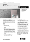
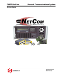
Conettix D6600/D6100i
System Guide
EN
Network
Communications
D6600 | System Guide | Contents
Contents
1.0
1.1
2.0
2.1
2.1.1
2.1.2
3.0
3.1
3.2
3.3
3.3.1
3.3.2
3.4
3.4.1
3.4.2
3.4.3
3.4.4
4.0
5.0
5.1
5.2
5.3
5.4
5.4.1
6.0
2
Introduction........................................................................................................................................... 3
Other Literature Referenced ................................................................................................................ 3
Overview................................................................................................................................................ 3
Conettix D6600/D6100i Pre-Installation Requirements ........................................................................ 6
Setting Up the Conettix D6600/D6100i over an Ethernet Network ....................................................... 6
Host Computer for Conettix D6600/D6100i System Setup ................................................................. 6
Operation............................................................................................................................................... 6
Setting Up the Host Computer ............................................................................................................. 6
Network Failover Solution (D6600 Only) ............................................................................................. 9
Conettix Datagram Type Differences ................................................................................................. 10
Datagram 02 ...................................................................................................................................... 10
Datagram 07 ...................................................................................................................................... 11
Networking and Encryption ................................................................................................................ 12
Using Encryption for the First Time .................................................................................................... 12
Upgrading Encryption ........................................................................................................................ 12
Using Two D6680s or D6682s in a System........................................................................................ 13
Obtaining the Latest D6200CD Software ........................................................................................... 13
Special Conettix D6600 Applications ............................................................................................... 14
D6100i Configuration Setup Instructions......................................................................................... 15
Identifying the MAC Hardware Address ............................................................................................. 15
Getting an IP Address........................................................................................................................ 15
Initial IP Address Assignment Using ARP.EXE .................................................................................. 15
Using Telnet to Finish the Configuration ............................................................................................ 16
Configuration Using Telnet................................................................................................................. 16
Configuring for D6100i Network Communication ........................................................................... 18
Bosch Security Systems, Inc. | 4/10 | 4998122712-04
D6600 | System Guide | 1.0 Introduction
.
2.0 Overview
Trademarks
Trademark names are used throughout this
document. In most cases, these designations are
claimed as trademarks or registered trademarks in
one or more countries by their respective owners.
Rather than placing a trademark symbol in every
occurrence of a trademark name, Bosch Security
Systems, Inc. (hereinafter referred to as Bosch) uses
the names only in an editorial fashion and to the
benefit of the trademark owner with no intention of
infringing the trademark.
Microsoft, Windows, Windows 2000, Windows XP,
Windows Vista, and Windows 7 are either registered
trademarks or trademarks of Microsoft Corporation in
the United States and/or other countries.
The Conettix D6600/D6100i System supports data
network communications. Conettix allows the
D6600/D6100i Receiver to connect to Ethernet
networks and process messages to and from most
networks using User Datagram Protocol/Internet
Protocol (UDP/IP) protocol. Connection to a data
network can be implemented through a COM4 or
COM1 connection from the D6600 to the
D6680/D6682 or directly from the D6100i Ethernet
port. Reports from alarm control panels through
phone lines or Ethernet data networks can be sent to
the D6600/D6100i and the central station automation
software. Alarm control panels can be monitored on
the network for their status.
Figure 1:
D6600 Communications
Receiver/Gateway
Figure 2:
D6100i Communications
Receiver/Gateway
1.0 Introduction
This system guide covers the installation, operation
and programming of the D6600/D6100i Conettix
Network Communications .
References are made to the following control panels:
D9412GV2, D7412GV2, D7212GV2, D9412G,
D7412G, D7212G, D9412, D9112, D7412, and
D7212. Throughout the remainder of this manual,
these control panels are referred to as “Bosch control
panels.”
1.1
Other Literature Referenced
This manual refers to other documentation with
additional information. Table 1 lists the complete part
number for ordering purposes.
Table 1: Other Literature Referenced
Name of Document
Conettix DX4020 Ethernet Network
Interface Module Installation Guide
D9133TTL-E Serial Interface Module
Installation Guide
C900TTL-E Dialer Capture Module
Installation Guide
Conettix D6680 Ethernet Network
Adapter Installation Guide
Conettix D6200
Programming/Administration Software
Operation and Installation Guide
Conettix D6682 Network Ethernet
Adapter Installation Guide
Conettix ITS-DX4020-G GPRS/GSM IP
Communicator Module Installation and
Operation Guide
Part Number
F01U045288
4998122717
4998122718
4998138732
4998154991
F01U078049
F01U163066
Bosch Security Systems, Inc. | 4/10 | 4998122712-04
The D6600/D6100i Software can be upgraded
through any network connection. The D6600/D6100i
can be programmed remotely through the D6200
Programming/Administration Software.
The D6600 has two COM ports on the back for
network communication connections, COM4 and
COM1 (optional). The D6600 requires a separate
D6680/D6682 for each COM port for interfacing with
an Ethernet network. Most applications do not initially
require using both COM ports.
The D6100i has a built in Ethernet port.
3
D6600 | System Guide | 2.0 Overview
Table 2: Network Adapters Part Numbers
Part Number
D6680-E120
ITS-D6682-UL
ITS-D6682-INTL
Application Description
Ethernet Network Adapter
D6682 supplied with a
UL-approved transformer
(Group West/Part number 48D-12-900).
D6682 supplied with a
international power supply with
regional adapters
All alarm panels (from Bosch or other manufacturers)
using the Conettix D6600/D6100i Network System
must have an interface (as described above) to allow
for network reporting. One method of interfacing an
alarm panel to a network is to use the C900V2 Dialer
Capture Ethernet Module.
The C900V2 and C900TTL-E operate with these
formats by using dial tone and handshake
simulations. The C900V2 and C900TTL-E intercept
the alarm panel’s signals and transmit them across
the network to a network-enabled D6600/D6100i.
For UL Fire Listed applications, refer to
the C900V2 UL Listed FACPs
Compatibility List (P/N: F01U010036) or
the C900TTL-E Compatibility List
(P/N: 4998141056).
For control panel manufacturers other
than Bosch, refer to the specific panel
installation guide for wiring, mounting and
installation instructions.
For control panel manufacturers other
than Bosch, refer to the specific panel
installation guide for wiring, mounting,
and installation instructions.
The C900V2 and C900TTL-E modules (refer to
Figure 3, page 5) operate with almost any alarm panel
(Bosch or other manufacturer) that uses a standard
digital dialer with one of the following industry
standard formats:
4
•
All Radionics Modem formats
•
DTMF
•
DTMF (where dialer retransmits quickly)
•
BFSK (2300 Hz ACK & 1400 Hz ACK Tone)
•
FBI Superfast DTMF (2300 Hz & 1400 Hz ACK
Tone)
•
Pulse 3/1, 3/1 Checksum (2300 Hz & 1400 Hz
ACK Tone)
•
Pulse 4/2 (Long 2300 Hz & Long 1400 Hz ACK
Tone)
•
SIA Bell 103 (110/300 baud, 2016 Hz ACK Tone)
•
ADT-SIA
•
Telim
•
Robofon
•
SIA Bell 103 (110/300 baud, 2083 Hz ACK Tone)
•
SIA V.21 (110/300 baud)
•
Seriee DTMF
•
Seriee FSK
Bosch Security Systems, Inc. | 4/10 | 4998122712-04
D6600 | System Guide | 2.0 Overview
.
Figure 3:
System Connection Diagram using
C900V2 or C900TTL-E and Any
Alarm Panel
2
Figure 4:
4
3
System Connection Diagram using
Network Modules and Bosch
Control Panels
5
1
4
3
2
5
1
A NE L
P
12 3
4 56
7 891 0
O
F
E LCO
T
1 2 4 8
11
15
11
6
15
6
7
14
10
12
11
7
14
8
8
9
10
12
11
9
13
1 - Any manufacturer’s control panel
2 - Connection – Control panel to
C900V2/C900TTL-E Ethernet jack
3 - C900V2 or C900TTL-E
4 - Connection – C900V2/C900TTL-E Ethernet
jack to Ethernet hub
5 - Host PC- 6200 Programming Administrative
Software
6 - Connection - Host PC Ethernet NIC to
Ethernet hub
7 - Ethernet hub
8 - Connection - Ethernet hub to D6100i
9 - D6100i
10 - Connection - Ethernet hub to D6680/D6682
11 - D6680/D6682
12 - Connection - D6680/D6682 to D6600 COM1
(optional)
13 - D6600
14 - Connection - D6680/D6682 to D6600 COM4
15 - Connection - Ethernet hub to D6680/D6682
The other type of network interface for alarm panels is
the D9133TTL-E, DX4020, or ITS-DX4020-G Network
Interface. These modules are designed for use with
Bosch control panels only. These modules and the
Bosch control panels communicate using the control
panel bus rather than the dialer capture method used
by the C900V2/C900TTL-E.
Figure 4 is a diagram of a Conettix D6600/D6100i
System using Bosch control panels: D9133TTL-E,
DX4020, or ITS-DX4020-G, D6600, D6100i, and
D6680/D6682.
Bosch Security Systems, Inc. | 4/10 | 4998122712-04
13
1 - Bosch control panel
2 – Connection – Control panel bus to
D9133TTL-E /DX4020/ ITS-DX4020-G bus
3 - D9133TTL-E, DX4020, or ITS-DX4020-G
4 - Connection – D9133TTL-E/ DX4020/
ITS-DX4020-G Ethernet jack to Ethernet hub
5 - Host PC- 6200 Programming Administrative
Software
6 - Connection – Ethernet hub to host PC
Ethernet NIC
7 - Ethernet hub
8 - Connection – Ethernet hub to D6100i
9 - D6100i
10 - Connection - Ethernet hub to D6680/D6682
11 - D6680/D6682
12 - Connection - D6680/D6682 to D6600 COM1
(optional)
13 - D6600
14 - Connection - D6680/D6682 to D6600 COM4
15 - Connection - Ethernet hub to D6680/D6682
The D6200 Programming/Administration Software is a
D6600/D6100i programming utility that works over a
network connection. Each network interface device
(D6680/D6682, D9133TTL-E/DX4020/ITS-DX4020-G,
or C900V2/C900TTL-E) must be added to the
Address Resolution Protocol (ARP) and is used to
temporarily associate an IP address with a hardware
address table, then configured through a telnet
session before network communications will function.
5
D6600 | System Guide | 3.0 Operation
For the appropriate configuration information for each
device, refer to the following installation guides:
•
•
•
•
•
•
•
C900TTL-E Dialer Capture Module Installation
Guide (P/N: 4998122718)
Conettix C900V2 Dialer Capture Ethernet
Module Installation Guide (P/N: F01U003472)
D9133TTL-E Serial Interface Module Installation
Guide (P/N: 4998122717)
Conettix DX4020 Ethernet Network Interface
Module Installation Guide (P/N: F01U045288)
Conettix D6680 Ethernet Network Adapter
Installation Guide (P/N: 4998138732)
Conettix D6682 Network Ethernet Adapter
Installation Guide (P/N: F01U078049)
Conettix ITS-DX4020-G GPRS/GSM IP
Communicator Module Installation and Operation
Guide (P/N: F01U163066)
2.1
For UL Listed Fire Installations, shared
on-premises communications equipment
is required to be UL Listed for Information
Technology Equipment.
2.1.1
•
•
•
6
Setting Up the Conettix D6600/D6100i over
an Ethernet Network
The Ethernet network must use Ethernet cables.
The D6200 host computer must have a properly
configured Ethernet network interface card (NIC)
installed.
The D6600 must be connected to the Ethernet
network using a Bosch D6680/D6682 Network
Adapter or a D6100i must be connected to the
Ethernet network.
All alarm control panels, except Bosch control
panels, used in the Conettix system must use a
Bosch C900V2 or C900TTL-E.
Bosch control panels used in the Conettix system
should use a Bosch DX4020 Network Interface
Module or a D9133TTL-E Network Interface
Module.
Host Computer for Conettix D6600/D6100i
System Setup
•
The host computer uses the ARP and TELNET
DOS commands to configure the D6680/D6682,
D6100i, D9133TTL-E or DX4020, or
C900V2/C900TTL-E. The D6200 software can be
used instead of the ARP and TELNET
commands. Refer to the D6200 Software
Operation and Installation Guide
(P/N: 4998154991) and the appropriate network
device installation guide.
•
The host computer must have a properly
configured Ethernet network interface card (NIC)
installed.
•
The host computer must have the appropriate
Ethernet cable. Manually set the host computer's
IP address to an address that is acceptable to the
particular class of the network (refer to
Section 3.1 Setting Up the Host Computer,
page 6).
Conettix D6600/D6100i
Pre-Installation Requirements
Consider the following pre-installation requirements
before attempting to install a Conettix D6600/D6100i
Network system. If you have any questions regarding
these items, contact the network administrator for the
network with which you will interface, or a Bosch
network engineer.
•
•
2.1.2
3.0 Operation
3.1
Setting Up the Host Computer
If the computer you plan to use for
programming the D6600, the D6100i, the
D6680/D6682, and the alarm panel
network adapters is already a functioning
workstation within the network you are
planning to utilize, proceed to Section 3.2
Network Failover Solution
(D6600 Only) on page 9.
The host computer is any computer or workstation
that is connected to the network you will use to
manage/administer the D6600/D6100i and other
devices. Any existing laptop or desktop computer on
the network can be used. However, for security
reasons, it is best that the computer not be used as a
regular workstation. This computer is also the
computer on which you install the D6200 Software.
The D6200 Software is used to program and
administer the D6600/D6100i and other devices.
Separate sections are provided for setting up the host
computer in Windows 2000, XP, Vista, and
Windows 7.
Bosch Security Systems, Inc. | 4/10 | 4998122712-04
D6600 | System Guide | 3.0 Operation
.
If the host computer is running Windows XP, 2000,
Vista, or Windows 7 and is new to the network, you
must perform the following steps:
5. Scroll in the Components checked are used by
this connection: list and select Internet
Protocol (TCP/IP).
Although the screen captures in this
procedure are specific to Windows 2000,
they are similar for Windows XP, Vista,
and Windows 7.
1. Select Start Æ Settings Æ Control Panel.
2. When the control panel is open, find and doubleclick the Network and Dial-up Connections icon
to launch the Network and Dial-up Connections
control panel.
6. Select the protocol icon for TCP/IP and click
Properties.
3. Double-click Local Area Connection.
7. When the dialog box appears, select Use the
following IP address:.
Enter an IP address and subnet mask for the
network you are setting up.
4. Right-click the icon and select Properties.
If you have any questions about the
assignment of the IP address or subnet
mask, contact the network administrator.
Bosch Security Systems, Inc. | 4/10 | 4998122712-04
7
D6600 | System Guide | 3.0 Operation
You must enter the correct subnet mask
and gateway for all devices that are on
this network. Contact the network
administrator for these values.
8. If necessary, copy the requested files to the
computer. This might require Microsoft Windows
operating system disk for the version you are
using.
9. After copying the files, you might need to restart
the PC. If so, connect the host PC’s NIC card to
the network (hub) and restart the PC.
10. After the PC restarts, perform the following check
to see if the previous procedures were entered
correctly.
Select Start Æ Programs Æ Accessories Æ
Command Prompt to open the Run dialog box.
A command prompt window appears.
Type ipconfig and press [ENTER].
11. The IP configuration for the PC is returned. The
following information is shown:
•
Connection-specific DNS Suffix
•
IP Address
•
Subnet Mask
•
Default Gateway
Verify the IP address, subnet mask, and
all other listed information. This
information should match the IP and
subnet mask you assigned to this
computer in the previous steps.
If you have chosen to program the
D6600/D6100i’s initial network
parameters using the direct null modem
serial connection, continue with the
following steps. These steps are
necessary only if the host computer
running the D6200 Software is connected
to the D6600/D6100i’s COM4 port using a
direct NULL modem serial cable.
12. Select StartÆ SettingsÆ Control Panel to open
the Control Panel.
13. When the Control Panel window opens, doubleclick the System icon.
14. The System Properties window opens.
8
Bosch Security Systems, Inc. | 4/10 | 4998122712-04
D6600 | System Guide | 3.0 Operation
.
15. Select the Hardware tab.
21. Select the Port Settings tab
16. Click the Device Manager button.
22. Select 38400 bits per second baud rate from the
Bits per second: drop-down menu, then click
OK.
A hardware tree appears showing all the devices
connected to the PC.
3.2
17. Click the plus sign ( ) next to Ports (COM &
LPT) to reveal the individual ports.
18. Highlight the Communications Port (COM1)
used to connect the D6200 Communications
Software to the D6600 COM4 port using a direct
connect null cable.
19. Right-click and select Properties from the menu
that appears.
20. The Communications Port (COM1) window
appears with four tabs across the top.
Bosch Security Systems, Inc. | 4/10 | 4998122712-04
Network Failover Solution
(D6600 Only)
An installed Conettix System should have at least two
D6600s and two D6680s/D6682s to allow for a
redundant backup to the first system in the event of a
system Number 1 failure. To allow for a redundant
backup of the D6680/D6682, program the IP address
of D6680 Number 1 into D6680/D6682 Number 2.
This allows for a change-over from D6680/D6682
Number 1 to D6680/D6682 Number 2. This might
seem like a simple solution, but it is much more
complex than it appears. In a network environment,
the MAC address plays a crucial role in delivery of the
data to the D6680/D6682. By simply switching from
D6680/D6682 Number 1 to D6680/D6682 Number 2,
no data would be delivered to D6680/D6682 Number
2 immediately after switching. This section does not
explain why this happens, but how to overcome this.
Software version 5.5C or greater must be
installed in the D6680 for the Alternate
MAC Address function.
In Figure 5, page 10, each of the D6680s is
programmed with the same IP address, but only one
is connected to the network at the same time by using
an AB switch. This switch could be a larger switch
that also changes the phone lines from one D6600 to
the other, or any other type of switch that the location
might use as long as it switches the network
connection from one D6680 to the other.
9
D6600 | System Guide | 3.0 Operation
Figure 5:
D6680/D6682 Connection
Do not connect both D6680s/D6682s to
the network at the same time.
4. After completing these settings, you must do two
additional settings:
1234567-
D6600 Number 1
D6600 Number 2
Null modem cable
D6680/D6682 Number 2
A/B Network switch
Network switch
D6680/D6682 Number 1
In Figure 5, another necessary programming
parameter is an Alternate MAC Address. The
Alternate MAC Address function allows a switch
between the D6680s/D6682s to occur without the
network detecting that anything changed. Program
the D6680s/D6682s as follows:
1. Program D6680/D6682 Number 1 as described in
the D6680 Ethernet Network Adapter Installation
Guide (P/N: 4998138732) for all parameters
including Channel 1. Use Port 7700 as the default
port number (this port can be different as
described in the D6680 Ethernet Network Adapter
Installation Guide). Program Channel 2 with the
same settings that are in Channel 1. Change the
port number to any value other than the port
number assigned to Channel 1 (any value
between 2000 and 10000). If using encryption,
perform the setup as in the D6680 Ethernet
Network Adapter Installation Guide. Save the
settings and exit the telnet session.
2. Write down the MAC Address of D6680/D6682
Number 1. This will be needed during the setup of
D6680 Number 2.
3. Program D6680/D6682 Number 2 with the same
settings that you entered into D6680/D6682
Number 1, do not save and exit but continue to
Step 4.
10
•
Under Expert Settings (Menu Item 5), locate
the Alternate MAC Address prompt. At this
prompt, enter the MAC Address of
D6680/D6682 Number 1.
•
Under Security Settings (Menu Item 6),
change the prompt for Alternate MAC to a Y
so that the D6680/D6682 uses the Alternate
MAC Address programmed in Menu Item 5.
Save the settings.
5. Connect the cabling as shown in Figure 5 on
page 10. Ensure that there is a switch box for the
network cable connection.
6. In the D6200 software, add two receivers as
follows:
•
Add the first receiver and name it Primary
Receiver, with the Receiver IP Address and
Receiver Port number for Channel 1 of the
D6680s/D6682s.
•
Add the second receiver and name it Backup
Receiver with the Receiver IP Address and
Receiver Port number for Channel 2 of the
D6680s/D6682s.
7. In the D6200 software, select the Primary
receiver when programming changes are needed.
After all program settings are sent to the Primary
Receiver, change the receiver in the Connection
settings to Backup Receiver and send the same
parameters to the backup receiver.
3.3
Conettix Datagram Type
Differences
Install software version 5.5C or later in
the network device (C900TTL-E,
D9133TTL-E, or D6680) for the Datagram
Type Function.
Software version 1.5D or later must be
installed in the DX4020 or C900V2.
3.3.1
Datagram 02
This datagram uses the IP address and the port
number to identify and ACK packets from the receiver
to the field devices which allow multiple devices to be
installed behind a single outgoing IP address. This
datagram type requires that CPU version 01.02.01 or
later is installed, and that receiver parameter 6.8.6 is
programmed as 1.
Bosch Security Systems, Inc. | 4/10 | 4998122712-04
D6600 | System Guide | 3.0 Operation
.
To use this datagram type, program it in the following
order:
1. Confirm that D6200 version 1.20 or later is
installed.
2. Confirm that the D6600 CPU version 01.02.01 is
loaded in the receiver.
3. With the D6200 software, select Network Æ
Network Configuration Management Æ
Read/Manage Network Configuration from
Receiver.
3. At the Port Number selection, enter a source port
that is not being used by another NIM on the
same network (such as 7701, 7702, 7703, and so
on). Keeping a list of the network modules on a
particular network along with the source ports of
those modules will ensure that duplicate source
ports are not used.
4. At the Datagram selection, enter 07 and press
[Enter].
4. Select the 6.8 Global Parameters tab.
5. At the Remote Port selection, enter the port
number that is used in the D6680/D6682 for the
D6600.
5. Change the 6.8.6 6600 Datagram Type value to
1.
6. Save the settings and exit from the setup of the
NIM.
6. Send the changes to the receiver and close the
window.
Outgoing packets from a network over a single IP
address go through a router or firewall that uses NAT
tables to keep track of which packets come from
which internal IP addresses. The NAT table ensures
that the returning packets for a device are forwarded
to the device that sent out the first packet. An
example of this is multiple PCs on a network
connecting to the Internet through a single IP address
from an ISP. By using the same idea, network
devices can perform the same function.
7. Select Network Æ Network Utilities Æ Network
Device Setup and select the Telnet to Device
tab.
8. Type or find the IP address of the D6680/D6682
in the list and establish a telnet session with the
D6680/D6682.
9. After establishing the telnet session, select the
channel(s) to use by pressing [1] or [2], and then
press [Enter].
10. Press [Enter] until you have selected Datagram
and type 02, then press [Enter]. If both channels
are used, change both channels.
11. Save the settings and exit from the D6680/D6682
setup.
3.3.2
Datagram 07
This datagram is supported only on the
E2-RAD version of the D9133TTL-E
Network Interface Module.
This datagram type is used only in the NIM of the
network device (D9133TTL-E, or DX4020). The
datagram type allows the Source and Destination
ports to be set independently. This use of a different
source port allows NAT (Network Address
Translation) tables of routers or firewalls to direct
packets to the correct NIM of the field device.
Table 3 on page 11 shows an example of what the
NAT table remembers when packets are sent to a
destination. An outgoing packet is sent to an IP
address with Source and Destination ports in that
packet. The Destination port is the port number that
the device uses when it receives data. After receiving
the data, the device processes it and sends a packet
back to the IP address that sent the data.
Table 3: NAT Table
Internal IP Address
192.168.1.11
192.168.1.12
192.168.1.13
Source Port
7700
7701
7702
When the data is returned to the router or firewall
software, the NIM directs the returning packet to the
correct internal IP address based on the NAT table.
To use this datagram type, program in the following
order:
1. Telnet to the NIM of the field device as described
in the appropriate network device (D9133TTL-E
or DX4020) installation guide.
2. Select channel 1 of the NIM.
Bosch Security Systems, Inc. | 4/10 | 4998122712-04
11
D6600 | System Guide | 3.0 Operation
3.4
Networking and Encryption
If you are considering using or are
currently using networking and
encryption, read the following information
carefully.
In all cases, encryption is performed in the NIM
(Network Interface Module) that is used in the
D6680/D6682, D9133TTL-E, C900V2/C900TTL-E,
and DX4020. When encryption is used, the
encryption key coming to the D6600 must be the
same key used on all field devices that are reporting
to that IP address. Because you can use up to two
NIMs on the D6600, several combinations can be
used:
•
Both NIMs using encryption – two NIMs can use
different keys or the same key
•
One NIM using encryption, the other not using
encryption
•
Neither NIM using encryption
If encryption is On in the NIM at the D6600, then it
must be On in the field devices. If it is Off in the NIM
at the D6600, then it must be Off in the field devices.
•
•
If you are not currently using encryption, refer to
Section3.4.1 Using Encryption for the First Time
on page 12.
If you are currently using encryption, refer to
Section 3.4.2 Upgrading Encryption on page 12.
3.4.1
Using Encryption for the First Time
When deciding to use encryption for the first time:
1. Check the hardware versions of the NIMs that will
be used in the system. If all of the hardware
versions used in a system do not match the
versions listed below, encryption cannot be used
on that system when they all report to one
D6680/D6682. Any device that is not at the
required hardware version must be replaced with
a current version before it supports encryption.
12
•
The D6680 must be a COBOX-FL-01 version.
This is the only hardware version that
supports encryption. The COBOX-E2-01
cannot be used.
•
The D9133TTL-E and C900TTL-E NIMs must
be CM-E2-RAD versions. This is the only
hardware that supports encryption. The
CBXM-ERAD cannot be used.
2. Check the firmware versions of the NIMs that will
be used in the system. For NIST approved AES
support, the version must be 5.16 or later. The
latest version is available on the D6600CD (v1.10
or higher) and the web site. To upgrade the
firmware in the CoBox, refer to the DeviceInstaller
Operation and Installation Guide
(P/N: 4998138688). DeviceInstaller version 2.01
(or later) is required to upgrade the firmware in
the NIMs.
For more information on how to obtain a
new D6200CD or how to obtain access to
the Web site, refer to Section 3.4.4
Obtaining Latest D6200CD Software on
page 16.
3. When enabling encryption on any NIM, it
communicates only with a NIM that also has
encryption enabled and has the same encryption
key programmed in it. This means that when you
enable encryption, all devices must be
programmed in order for them to communicate
with the D6680/D6682. During the time that it
takes to program the encryption key into the
NIMs, the devices will not communicate with the
D6680/D6682.
4. You can have two D6680s/D6682s on one
D6600, one having encryption On and the other
having it Off. This would allow for field devices to
communicate with the D6680/D6682 with
encryption Off and begin the programming of the
field devices to send with encryption On to the
second D6680/D6682. This would allow devices
to be programmed for encryption without the loss
of any signals or data to the D6600. For more
information on how to use two D6680s/D6682s in
a system as described, refer to Section 3.4.3
Using Two D6680s or D6682s in a System on
page 13.
3.4.2
Upgrading Encryption
If encryption is currently being used at a site that was
set up before to the release of D6600CD v1.10 or NIM
firmware versions before to v5.16 on the TTL-E
devices, there are some items to consider before
using other releases.
To ensure that NIST approved encryption is being
used and communication between the NIMs
continues, upgrade all TTL-E NIMs to v5.16 or later,
D6200 v1.10 or later, and D6202 v2.3 or later. All
versions of NIMs, D6200 software, and D6202
software are shipped with the latest software and
firmware installed.
Bosch Security Systems, Inc. | 4/10 | 4998122712-04
D6600 | System Guide | 3.0 Operation
.
You can have two D6680s/D6682 on one D6600, one
with encryption On and the other with encryption Off.
This setup would allow for field devices to continue to
communicate with the D6680/D6682 with encryption
Off and begin the programming of the field devices to
send with encryption On to the second D6680/D6682.
This would allow devices to be programmed for
encryption without the loss of any signals or data to
the D6600. For more information on how to use two
D6680s/D6682s in a system as described, refer to
Section 3.4.3 Using Two D6680s or D6682s in a
System on page 13.
3.4.3
Using Two D6680s or D6682s in a System
If you will use two D6680s/D6682s in a system, both
using encryption (v5.16 or later) or one using
encryption and the other unencrypted, then do the
following steps:
1. The following equipment is needed:
•
If the device is a D9133TTL-E/DX4020,
change the destination IP address that is
currently programmed for the control panel to
the encryption-enabled D6680/D6682.
9. The devices that are programmed with encryption
communicate through the encryption-enabled
D6680 (v5.16 or later)/D6682, while the nonencrypted devices, or those using encryption v5.1
or earlier, communicate through the original
D6680/D6682.
3.4.4
Obtaining the Latest D6200CD Software
If you do not already have the latest D6600CD (v1.10
or later) or D6200CD (v1.24 or later), you can obtain a
correct CD by of the following methods:
•
Call and order a D6200CD from the Bosch
Customer Service group by calling 1-800-2890096.
•
Download the released software, firmware, and
documentation from the Bosch web site.
•
One additional D6680/D6682
•
One additional static IP Address
Downloading
•
A D6672 COM1 Expansion Kit for the D6600
1. Connect to the company web site:
www.boschsecurity.us, then search for D6600.
You can download software, firmware, and
documentation from the Conettix D6600 product
page.
2. D6680/D6682 Number 1 is the network adapter
that is currently running.
3. Assuming the first D6680/D6682 is already set up
and running, connect the second D6600 on
COM1 to the D6600/D6100i as described in the
D6600/D6100i Network Operation and Installation
Guide (P/N: 4998122704).
Download times can vary depending on
the speed of your Internet connection.
4. Enable encryption in the second D6680/D6682 as
described in the Conettix D6680 Network Adapter
Installation Guide (P/N: 4998138732), or the
Conettix D6682 Network Ethernet Adapter
(P/N: F01U078049).
2. Read the D6600/D6100i Release Notes
(P/N: 4998122709) for the latest information
regarding software installation, changes, and
added features.
5. Add a receiver to the list of receivers under
Administration Æ Connection Settings with the
IP address and encryption key of the second
D6680/D6682.
A decompression program that handles
.zip files is required in order to open the
zipped file.
6. Select the receiver name added in the previous
step.
7. Verify that the D6200 can communicate with the
D6600.
3. Follow the installation procedures for software
and firmware in the Software Upgrade Procedure
section of the D6600/D6100i Operation and
Installation Guide (P/N: 4998122704).
8. Program field devices to communicate with the
encryption enabled D6680/D6682:
•
Verify that the TTL-E NIM has the correct
firmware (v5.16 or later).
•
Enable encryption on the NIM device with the
same key that is entered in the D6680/D6682.
•
If the device is a C900TTL-E/C900V2,
change the destination IP address to match
the IP address in the encryption-enabled
D6680/D6682.
Bosch Security Systems, Inc. | 4/10 | 4998122712-04
13
D6600 | System Guide | 4.0 Special Conettix D6600 Applications
4.0 Special Conettix D6600 Applications
The following special application has been requested by Bosch dealers. It is included here to assist you if you
have the same requirement. If you have any questions, contact Technical Support at (800) 289-0096.
Emulating a Direct Serial Connection Over a LAN Using D6680/D6682 Ethernet Network Adapters
Some applications might require a direct serial connection be emulated over the network. One application that
would require this is where the D6600 is located on another part of the network from the Automation System.
To create a direct serial connection between the D6600 and the automation system, connect the COM3
automation output from the D6600 to the two D6680s/D6682s on the system. This is true serial cable emulation
over the network (refer to Figure 6 on page 14).
Figure 6:
Direct Serial LAN Connection Configuration
COM3
192.158.001.017
1
123-
D6680
#2
D6680
#1
2
RS232
192.168.001.016
3
D6600 Receiver
Ethernet
Automation System
The commands necessary for this configuration to automatically establish a connection are as follows. Note the
reference to the D6680s/D6682s by their number (Number 1 or Number 2). You must also ensure that the port
parameters such as speed, number of bits, flow control, and so on are correct on the D6680/D6682 for the
serial device that they are connected to.
D6680/D6682 No. 1:
D6680/D6682 No. 2:
*** basic parameters
Hardware: Ethernet TPI
IP address: 192.168.001.017, no gateway set
*** basic parameters
Hardware: Ethernet TPI
IP address: 192.168.001.016, no gateway set
******* Channel 1 *******
Baudrate 9600, I/F Mode 4C, Flow 00
Port 7700
Remote IP Adr: 192.168.001.016, Port 7700
Connect Mode: C0
******* Channel 1 *******
Baudrate 09600, I/F Mode 4C, Flow 00
Port 7700
Remote IP Adr: 192.168.001.017, Port 7700
Connect Mode: C0
For more information, refer to the D6680 Ethernet Network Adapter Installation Guide (P/N: 4998138732), or
the Conettix D6682 Network Ethernet Adapter Installation Guide (P/N: F01U078049).
14
Bosch Security Systems, Inc. | 4/10 | 4998122712-04
D6600 | System Guide | 5.0 D6100i Configuration Setup Instructions
.
5.0 D6100i Configuration
Setup Instructions
5.1
Identifying the MAC Hardware
Address
You must program the IP address of the D6100i. The
first step is to determine the MAC, or hardware,
address of the D6100i. This address is hard-coded
into the D6100i during its manufacture and cannot be
changed. This address is 6 bytes (12 digits) long.
The following procedure shows how to use the ARP
command to assign an IP address to the D6100i.
The IP and MAC addresses in this
procedure are examples and are not
the same as those for your D6100i.
1. Select Start Æ Run.
The Run dialog box appears.
2. In the Run dialog box, type COMMAND and click
OK.
A DOS window appears:
Figure 7 shows an example of a MAC address label.
Figure 7:
MAC Address Label Example
3. At the DOS command line, type:
The MAC address label is located on
the rear of the D6100i below the
Ethernet port.
arp -s xxx.xxx.xxx.xxx zz-zz-zz-zz-zz-zz
and press [ENTER].
Record this number for future
reference.
5.2
Getting an IP Address
An IP address is an identifier for a computer or device
on a TCP/IP network. The IP address is a 32-bit
numeric address written as four numbers separated
by periods. Each number can be zero to 255, for
example, 190.200.128.111. In an isolated network,
you can assign IP addresses at random if each one is
unique. Connecting a private network to the Internet
requires registered IP addresses (called Internet
addresses) to avoid duplication.
5.3
Initial IP Address Assignment
Using ARP.EXE
Bosch Security Systems, Inc. | 4/10 | 4998122712-04
xxx.xxx.xxx.xxx is the IP address the
network administrator assigned to
the D6100i.
•
zz-zz-zz-zz-zz-zz is the MAC
address printed on the back of the
D6100i.
For example:
The program responds with a prompt to indicate
that the address was accepted.
The D6100i you are configuring and the PC used to
configure it must both be on the same gateway (the
device that connects the LAN to the WAN) to use
telnet for configuration of the D6100i. The gateway
can be a router or a hub. After you configure the
D6100i and assign it an IP address, you can then use
telnet to change configuration parameters from
anywhere on the network.
Read this entire procedure before
starting. Ensure that power is applied
to the D6100i and then connected to
the LAN or WAN through the Ethernet
connector.
•
The program does not indicate that
the operation was performed properly.
The only indication is the absence of
an error message.
4. Verify that you entered the IP address correctly.
Type:
arp -g
and press [ENTER].
15
D6600 | System Guide | 5.0 D6100i Configuration Setup Instructions
This command displays the IP address 172.17.10.70
temporarily linked to MAC address
00-20-4a-12-04-0e as shown in Figure 8. The
temporary link shows a static entry.
Figure 8:
ARP Table
By default, Windows Vista does not
install the Telnet client. The Telnet client
is for text-based communication with
remote systems.
To install the Telnet client on a PC
running Windows Vista:
1. Click Start→Control Panel.
2. Select Programs and
Features.
3. Select Turn Windows features
on or off.
The network uses this table to identify devices and to
route signals. The number of devices and other types
(static and dynamic, as shown in the example)
depends on the network and the number and type of
devices with which this PC communicates. Identify the
MAC address of the device you are installing and
verify that it now has an IP address linked to it.
5.4
Using Telnet to Finish the
Configuration
To use Telnet, you must log in as a user
with Administrative privileges.
4. Select the Telnet Client option.
5. Click OK.
A dialog box opens to confirm
installation. The telnet command
is now available.
1. Select Start Æ Run.
The Run dialog box appears.
2. In the Run dialog box, type telnet and click OK.
The Telnet window appears.
In Windows Vista, Telnet is disabled by
default. In order to use Telnet, you must
enable it:
1. Click Start→Control
Panel→Programs.
2. Click Turn Windows features on
or off.
If you are prompted for an
administrator password or
confirmation, type the password or
provide confirmation.
3. In the Windows Features dialog
box, select the Telnet Client check
box.
4. Click OK.
The installation might take several
minutes.
3. Type open <IP ADDRESS> 1 and press [ENTER]
(where <IP ADDRESS> is the IP address of the
D6100i). Type a space after open and after the IP
address. For example:
open 172.17.10.70 1.
The connection fails the first time. This is normal.
4. Repeat Step 3 using 9999 as the port number.
5. Type open <IP ADDRESS> 9999 and press
[ENTER] (for example, open 172.17.10.70 9999).
6. Press [ENTER]. The Setup Mode information
appears.
The MAC address, IP address, gateway
IP address, and port number in this
procedure are examples and are not the
same as those for your C900V2.
Continue with Section 5.4.1 on page 16.
16
Bosch Security Systems, Inc. | 4/10 | 4998122712-04
D6600 | System Guide | 5.0 D6100i Configuration Setup Instructions
.
5.4.1
Configuration Using Telnet
The following prompt appears:
1. Type 0 (zero) and press [ENTER] to set up the
basic server configuration.
If the D6100i was previously programmed with an
IP address, the address appears in parentheses.
2. Type the IP address (for example,
190.200.128.219) and press [ENTER].
3. If the Gateway address is required, type y, press
[ENTER] and then type the address and press
[ENTER].
If the Gateway address is not required or if you
use DHCP, type n and press [ENTER]
5. Press [ENTER] to accept the password setting at
none.
In most cases, do not assign a
password. If a password is necessary,
store it in a safe place. If you lose or
forget the password, you cannot
connect to D6100i using telnet until you
send the unit to the factory for password
removal, and the unit is returned to you.
The Setup Mode information appears.
The following prompt appears.
The Gateway IP is required only if you
are connecting to a WAN. In a LAN,
the Gateway IP is usually not needed
unless the Gateway IP of the PC is
different from the Gateway to which
the D6100i is connected.
4. If Network needs to be changed from the default,
enter the number of bits that correspond to the
netmask your network uses and press [ENTER].
Refer to Table 4.
Contact your network administrator if you need
more information about the netmask.
Table 4: Netmask Address
Host
Bits
1
2
3
4
5
6
7
8
9
10
11
12
13
14
15
16
Netmask
255.255.255.254
255.255.255.252
255.255.255.248
255.255.255.240
255.255.255.224
255.255.255.192
255.255.255.128
255.255.255.0
255.255.254.0
255.255.252.0
255.255.248.0
255.255.240.0
255.255.224.0
255.255.192.0
255.255.128.0
255.255.0.0
Host
Bits
17
18
18
20
21
22
23
24
25
26
27
28
29
30
31
Netmask
255.254.0.0
255.252.0.0
255.248.0.0
255.240.0.0
255.224.0.0
255.192.0.0
255.128.0.0
255.0.0.0
254.0.0.0
252.0.0.0
248.0.0.0
240.0.0.0
224.0.0.0
192.0.0.0
128.0.0.0
Bosch Security Systems, Inc. | 4/10 | 4998122712-04
6. Type 1 and press [ENTER] to set up Channel 1
configuration.
This information appears.
If the default value displayed in your
Telnet window does not match the
value listed in any of the steps below,
type the correct value and press
[ENTER].
7. At the Baud Rate prompt, press [ENTER] to
accept the default (38400).
17
D6600 | System Guide | 5.0 D6100i Configuration Setup Instructions
8. At the I/F Mode prompt, press [ENTER] to accept
the default (4C).
9. At the Flow prompt, press [ENTER] to accept the
default (00).
10. Type a unique Port Number for the LAN to which
the D6100i is connected and press [ENTER].
11. At the ConnectMode prompt, press [ENTER] to
accept the default (CC).
12. At the Datagram Type prompt, type 00 or 02 and
press [ENTER].
13. At the IP addr prompt, type the remote IP
address used for the D6600 to which the C900V2
reports and press [ENTER].
Enter the remote IP address using
000.000.000.000 format.
15. Type the Port Number for the D6600 and press
[ENTER].
If you want to enable encryption, continue with the
next step. If not, go to step 27.
If encryption is enabled on the
D6100i, it must be enabled on all field
devices..
16. From the Change Setup menu, type 6 and press
[ENTER].
This information appears.
20. At the Disable Port 77FEh prompt, press
[ENTER] to accept the default (N).
Disabling the telnet and port 77FE
prevents you from accessing the set-up
menu for future changes.
21. At the Disable Web Server prompt, press
[ENTER] to accept the default (N).
22. At the Disable ECHO ports prompt, press
[ENTER] to accept the default (Y).
23. At the Enable Encryption prompt, type y and
press [ENTER].
24. At the Change keys prompt, type y and press
[ENTER].
25. Type the key and press [ENTER].
The key is 16 bytes (32 characters) long. Enter
the key using the 01-02-03-04-05-06-07-08-0910-11-12-13-14-15-16 format.
26. At the Enable Enhanced Password prompt,
press [ENTER] to accept the default (N).
27. Type 9 and press [ENTER] to save changes and
exit from the telnet session.
To confirm that the IP address is configured properly,
use the ping utility:
28. At the C:\> prompt, type ping <IP Address> and
press [ENTER].
Four reply messages are received, confirming the
D6100i is communicating on the network.
Configuration of the D6100i is complete.
17. At the Disable SNMP prompt, press [ENTER] to
accept the default (N).
18. At the SNMP Community Name prompt, press
[ENTER] to accept the default (blank).
19. At the Disable Telnet Setup prompt, press
[ENTER] to accept the default (N).
18
Bosch Security Systems, Inc. | 4/10 | 4998122712-04
D6600 | System Guide | 6.0 Configuring for D6100i Network Communication
.
6.0 Configuring for D6100i
Network Communication
The following steps allow the D6100i to communicate
with the host PC running the D6200 Programming
Software.
For the network communication to
function, install a properly configured
D6100i. Refer to the previous sections.
If network communications are not
installed, further D6200 software
programming using the network is not
possible.
1. On the D6100i keypad, press [MENU] and enter
the default passcode of [6][1][0][0] to enter the
programming mode. Press [ENTER] again.
To change any programming
parameter, follow this syntax:
•
•
•
Press [ENTER],
Enter the desired value,
Press [ENTER] again to store the
value.
2. Scroll down [ ] to 6 NETWORK
CONFIGURATION and press [ENTER].
3. Scroll down [ ] to 6.2 Network Adapter and press
[ENTER].
6.2 COM4 Network Adapter
4. Set 6.2.5 Network Adapter Enabled to a value of
1 and press [ENTER]. If the value is not 1, press
[ENTER][1][ENTER].
6.2.5 COM4 Network Adapter Enabled
Current setting [1]
9. Type 1 for 6500 mode or 2 for SIA mode and
press [ENTER] to enter the selection.
10. Press [CANCEL] and scroll down [ ] to
6.3.7 Device.
11. Press [ENTER].
12. Press [1] for automation communication through a
network, or [2] for automation communication
through the RS-232 COM3 port.
13. Press [CANCEL] and scroll down [ ] to 6.4 D6200
Network Connections.
14. Press [ENTER] to move to 6.4.1 IP Address 1.
15. Press [ENTER] again to enter the IP address of
the host PC that runs the D6200 Software.
When entering an IP address through
the keypad of the D6100i, press an
alpha character ([A] to [F]) to enter a
decimal point in the IP address.
For example, enter IP address 202.96.168.127
as:
[2][0][2][A][9][6][A][1][6][8][A][1][2][7][ENTER].
16. Scroll [ ] to 6.4.5 Network Programming Enable.
Verify that the value is 1. If the value is not 1,
press [ENTER][1][ENTER].
17. Press [CANCEL] repeatedly to return to the idle
stage (time and date show on the LCD).
5. If the D6100i has encryption enabled, Set 6.2.6
Network Encryption Enabled
to 1.
6. Press [CANCEL] and scroll down [ ] to
6.3 Network Automation Connection.
6.3 Network Automation Connection
7. Press [ENTER].
8. Scroll [ ] to 6.3.6 Network Automation Output
Format.
Bosch Security Systems, Inc. | 4/10 | 4998122712-04
19
Bosch Security Systems, Inc.
130 Perinton Parkway
Fairport, NY 14450
USA
www.boschsecurity.com
© Bosch Security Systems, Inc., 2010
4998122712-04