1
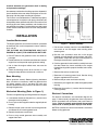
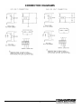
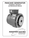
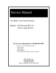
PANCAKE
CAPACITOR GENERATOR
Installation, Operation, and Maintenance Manual
TABLE OF CONTENTS
General Data
INTRODUCTION . . . . . . . . . . . . . . . . . . . . . . . . . . . . . 2
General Data . . . . . . . . . . . . . . . . . . . . . . . . . . . . . . 2
Initial Inspection . . . . . . . . . . . . . . . . . . . . . . . . . . . . 2
Construction:
Capacitor Excitation
Speed:
60 Hz 1850 rpm at no load
1800 rpm at full load
50 Hz 1550 rpm at no load
1500 rpm at full load
SAFETY . . . . . . . . . . . . . . . . . . . . . . . . . . . . . . . . . . . 2
INSTALLATION . . . . . . . . . . . . . . . . . . . . . . . . . . . . . . 3
Location / Environment . . . . . . . . . . . . . . . . . . . . . . 3
Base Mounting . . . . . . . . . . . . . . . . . . . . . . . . . . . . 3
Mechanical Mounting . . . . . . . . . . . . . . . . . . . . . . . 3
Electrical Connections . . . . . . . . . . . . . . . . . . . . . . . 3
Air cooled
OPERATION . . . . . . . . . . . . . . . . . . . . . . . . . . . . . . . . 4
Initial Start-up . . . . . . . . . . . . . . . . . . . . . . . . . . . . . 4
Capacitor Excitation/Voltage Regulation . . . . . . . . . 4
Max. Ambient Temp.
40°C
Insulation:
Class F
Voltage Response
0.1 sec.
Capacitor generators are designed to operate at a specific
frequency. For 50 hertz units, consult with the factory for
model selection.
MAINTENANCE . . . . . . . . . . . . . . . . . . . . . . . . . . . . . 4
Periodic Inspection . . . . . . . . . . . . . . . . . . . . . . . . . 4
Cleaning . . . . . . . . . . . . . . . . . . . . . . . . . . . . . . . . . 4
Initial Inspection
SERVICE . . . . . . . . . . . . . . . . . . . . . . . . . . . . . . . . . . . 4
Flashing the Rotor . . . . . . . . . . . . . . . . . . . . . . . . . . 4
Checking the Capacitor Charge . . . . . . . . . . . . . . . 5
Checking Diodes . . . . . . . . . . . . . . . . . . . . . . . . . . . 5
Ordering Parts . . . . . . . . . . . . . . . . . . . . . . . . . . . . . 5
Your Marathon generator has been carefully inspected and
tested before leaving the factory. However, it is wise to
examine the generator before installation. Carefully unpack
and examine the generator. If there is any damage, file a
damage claim with the shipper or agent immediately. Save
all packaging materials for inspection by agent.
RETURNED GOODS . . . . . . . . . . . . . . . . . . . . . . . . . 5
TROUBLE SHOOTING . . . . . . . . . . . . . . . . . . . . . . . . 6
SAFETY
CONNECTION DIAGRAMS . . . . . . . . . . . . . . . . . . . . 7
120 Volt, Two Lead Connection. . . . . . . . . . . . . . . . 7
240/120 Volt, Three Lead Connection . . . . . . . . . . . 7
PLEASE REMEMBER SAFETY FIRST. If you are not sure
of the instructions or procedures contained in this manual,
seek qualified help before continuing. When in doubt, ask.
This manual emphasizes the safety precautions necessary
during the installation, operation, and maintenance of your
Capacitor generator. Each section has caution and warning
messages. These messages are for your safety, and the
safety of the equipment involved. If any of the cautions or
warnings are not readily understood, seek clarification from
qualified personnel before proceeding.
INTRODUCTION
Before any service work is done, disconnect all power
sources and, where appropriate, lock out all controls to
prevent an unexpected start-up of the generator set driver.
Proper grounding (earthing) in compliance with local and
national electrical codes and standards must be provided.
These safety precautions are necessary to prevent
potential serious personal injury or even death.
Thank you for choosing a Marathon Electric Capacitor
Generator.
Please read the installation and service sections of this
manual carefully before starting the generator. A clean
environment and proper installation are as critical to
generator performance as the engineering of the internal
components. If you have any difficulty installing or servicing
your Marathon generator, our service and technical staff
will be happy to help you. We are confident that by following
these guidelines, you will get many years of reliable service
from your Marathon generator.
The hazards associated with lifting or moving your
generator are pointed out in the installation and service
sections. Incorrect lifting or moving can result in personal
injury or damage to the unit.
Prior to start-up of the unit ensure that all generator leads
are properly connected and insulated. Always assume
that there will be voltage present at the generator
2
terminals whenever the generator’s shaft is rotating
and proceed accordingly.
Use extreme caution when handling capacitors. A potential
shock condition exists even when the engine has shut off.
See page 4 for the proper handling of capacitors.
This manual is not intended to be a substitute for properly
trained personnel. Installation and repairs should only be
attempted by those qualified and trained. The cautions and
warnings point out known conditions and situations that
are potentially hazardous. Each installation may well create
its own set of hazards. No manual can cover every possible
situation.
INSTALLATION
Location/Environment
Figure 1 – General Assembly
The engine-generator set must be installed in a protected
environment, with a minimal exposure to fumes, moisture,
dust, and dirt.
f. Pull the rotor assembly from the frame. CAUTION: Do
not scratch or cut the copper stator winding when
removing rotor.
THE OUTSIDE AIR TEMPERATURE MUST NOT
EXCEED 40°C (104°F) FOR CONTINUOUS DUTY USE.
g. Bolt the rotor assembly’s drive disc to the engine
flywheel, using the proper size flat washers and S.A.E.
grade 8 bolts. Torque the drive disc mounting bolts to
the engine manufacturer’s specifications.
a. DO NOT obstruct the generator intake and outlet air
passages.
b. Provide sufficient air circulation around the set to remove
engine heat and to provide ample generator cooling.
h. Push the generator frame assembly carefully back over
the rotor. Mount the frame assembly to the engine
flywheel housing with the proper size bolts, lock washer,
and nuts.
c. Hot air from the engine radiator must not enter the
generator.
d. Check the mounting surface to be sure that it is rigid
enough to keep vibration and noise to a minimum.
i. Remount the exhaust screen band.
j. Reconnect all incoming power leads. See the wiring
diagram supplied with this manual.
Base Mounting
Mount generator securely. Before tightening hold-down
bolts, use shims as necessary under the generator feet
for uniform support. If this is not done, the frame may
become distorted resulting in excess vibration that could
damage the generator.
k. Remount the pot cover and fasten securely.
l. Remove the jack support from under the engine flywheel
housing.
m.Reconnect the positive (+) terminal lead to the engine
cranking battery.
Mechanical Mounting (Refer to Figure 1):
Electrical Connections
To mount a single-bearing capacitor generator to an engine:
b. Place a jack or other support under the engine flywheel
housing.
For electrical connections, see connection diagrams on
page 7. Ground (earth) the generator frame and neutral
lead in accordance with all National and Local Electrical
Codes. Failure to properly ground (earth) the generator
could result in severe personal injury or even death!
c. Remove the pot cover from the back of the generator
and disconnect all incoming power leads.
NOTE: Be sure that ALL electrical connections are correct
before starting generator.
a. If connected, disconnect the positive (+) terminal from
the engine cranking battery.
d. Remove the exhaust screen band.
e. Place a strap around generator rotor assembly and
support from hoist.
3
OPERATION
Capacitor Excitation/Voltage Regulation
A single capacitor is used to regulate the voltage to within
5% of the rated load. Use extreme caution when handling
capacitors. The capacitor will still contain high voltage even
after the engine has stopped operating.
Initial Start-up
a. Carefully inspect the generator before start-up. Check
all electrical connections, and ensure that all bolts have
been securely fastened.
Always discharge the capacitor before handling. Use an
insulated conductor (jumper wire) or a screw driver with
an insulated handle to short across the capacitor terminals,
and discharge the capacitor prior to handling.
b. Rotate the shaft. The shaft and rotor assembly should
turn freely. Do not use the fan as a fulcrum to bar
over the unit.
c. Start engine. See the engine manufacturer’s operating
manual for proper engine starting procedures.
MAINTENANCE
d. Check vibration. If excessive, check all mechanical
connections.
Periodic Inspection
Clean and inspect generator after every 200 hours of
normal operating time. If the generator is housed in a harsh
environment, it is advisable to clean and inspect the unit
more frequently. If dirt and grease is allowed to build-up,
the generator will run hotter, lose efficiency, and reduce
the life of the generator.
e. The generator voltage is adjusted at the factory to a
specified speed; however, it is advisable to verify upon
installation.
GENERATOR SPEED
Rating
60 Hz
50 Hz
No Load rpm
1800 – 1850
1500 – 1550
Minimum Full Load rpm
1800 less 1%
1500 less 1%
Remove pot cover to examine the rotor, shaft, and bearing
for excessive wear. Replace the bearing after 10,000 hours
of normal operating time or sooner if wear is evident.
f. Observe and record the generator voltage at no load
and at full load. Immediately after start-up (cold) and
after 30 minutes of full load (hot). The voltage is easily
adjustable by adjusting the engine speed. The voltage
will increase as the generator rpm is increased.
Cleaning
Remove all dust, dirt, and oil and grease build-up from
external surfaces. Use a low-pressure air hose (25-psi
maximum) to blow dirt and grease from the internal
components through the fan opening. Clean inside the
control box. Check for loose or damaged lead wires and
loose components mounted in the box.
g. If voltage cannot be adjusted, see the section on
TROUBLE SHOOTING, page 6.
h. Check the temperature rise after running for 30 minutes
at full load. If excessive, examine the generator for the
following:
NOTE: Do not remove any internal generator parts or
warranty is void.
1. Obstructed air flow
SERVICE
2 Hot air feeding into the inlet of the generator
3. Bypassed air (air not pulled through generator)
Flashing the Rotor - Refer to Figures 2 and 3
i. Examine ratings and actual load applied to determine if
the generator rating may be too low for the load applied.
NOTE: Do not run the generator during this operation.
The ambient temperature must not exceed 40°C.
(104°F). For operation at higher ambient temperatures,
reduce the generator kW rating 1% for each degree
above 40°C. For operation at high altitudes, reduce
the generator kW rating 2% for each 1000 ft above sea
level.
a. Disconnect all incoming power leads to the generator.
b. Connect the (+) lead of a 12 volt battery to the “R”
connection.
c Connect the (–) lead of the battery to the rotor shaft.
d. Disconnect battery leads.
Frame temperatures above 60°C. (140°F) are too high,
indicating a temperature rise in the copper windings of
105°C (121°F) or more.
e. Check the generator no load terminal voltage. It should
be within ±10% of rated value.
4
Checking Diodes
f. If residual voltage is normal, the capacitor is defective
and should be replaced.
a. Check each diode individually by removing the (+) rotor
lead stud connection (see Figures 2 and 3). Diodes are
good if the resistance reading is approximately midscale on the lowest ohm rating.
b. Check for leakage in each diode by reversing their
polarity. Diodes are good if the resistance reading is
infinite. A faulty diode will give a resistance value of zero.
c. Prior to installing a replacement diode, clean the surface
of the exciter rotor core, and run a bead of a thermalelectrical compound around the base of the diode. The
diode threads should not be coated.
d. Torque the diode base to 20–30 in-lb. Do not over
torque the diode base.
Ordering Parts
When ordering parts, always include the name and quantity
of each part along with the serial and model numbers from
the generator nameplate.
For parts ordering information, contact:
Marathon Electric Manufacturing Corporation
100 E. Randolph St.
P.O. Box 8003
Wausau, WI 54402-8003
Phone: 715.675.8257
or: 800.477.6362, ext. 8257
Figure 2
RETURNED GOODS
Consult Marathon Electric Manufacturing Corporation for
authorization before returning any product. We cannot be
responsible for any items returned without authorization.
CAUTION: Single bearing generators must have their
rotor assembly properly secured to prevent damage
during transit to the factory, or to an authorized service
center.
Figure 3
Checking the Capacitor Charge
a. Check the capacitor “charge and discharge” readings
using an ohmmeter on the RX-1000 scale.
b. Place the ohmmeter leads on the capacitor terminals
one at a time. A meter deflection should be seen
(charging), followed by a slow return to infinity
(discharging).
c. Reverse the ohmmeter leads and repeat the procedure.
The results should be the same. No meter deflection or
continuity indicates a defective capacitor. Replace the
device.
5
TROUBLE SHOOTING
Visual Examination
Inspect the generator visually. Look for obvious damage
such as: Charred windings, pinched wires, cracked
insulation, loose terminal lugs, etc. All connections should
be fastened securely. Check the operating speed and see
that the unit has been reassembled and reconnected
correctly.
SYMPTOM
Will not hold voltage - Loss
of residual magnetism
CAUSE
Unit has been stored.
SOLUTION
Flash Rotor (see SERVICE section).
Rotor shorting out when unit gets
hot.
Check rotor windings for broken or
burned wires.
Pinched leads.
Examine all lead wires and correct.
Defective Capacitor.
Replace.
Defective Diodes
Replace.
Defective Surge Suppressor.
Replace.
Loose or broken lead wires.
Check lead wires and connections for
broken wires and loose connections.
Compare connections with the wiring
diagram supplied with generator.
Rotor opened or shorted.
Measure resistance between leads.
Stator ground or shorted.
Consult Factory.
Loss of residual magnetism.
Flash Rotor (see SERVICE section).
Low engine speed.
Check engine speed and generator
ratings. 1800 rpm/60 Hz
Faulty diode.
Replace diode.
Voltage too high
Fast engine speed.
Check engine speed and generator
ratings. 1800 rpm/60 Hz
Uncontrollable voltage
Incorrect engine adjustment.
Check engine operation, speed, fuel
lines & injector.
No voltage at no-load or full-load
Faulty suppressor.
Disconnect from circuit. If there is an
obvious increase in voltage, replace
the suppressor.
Voltage spikes
appearing in sine wave
Incorrect engine adjustment, fuel
line, or poor gas.
Change fuel filter and check engine
speed.
Loose connection.
Inspect all connections.
Bad ground connection.
Inspect all ground connections.
Load induced.
Filter load.
Full voltage at no load
Voltage drops at full load
Low Voltage
6
CONNECTION DIAGRAMS
7
Marathon Electric Mfg. Corp.
100 East Randolph Street
P.O. Box 8003
Wausau, WI 54402-8003
Phone: (715) 675-3359
Fax:
(715) 675-8026
Printed in U.S.A.
GPN012 7/02