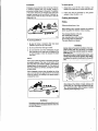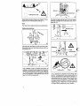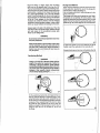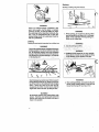
1
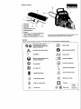
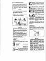
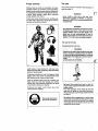
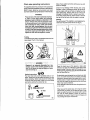
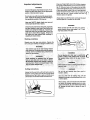
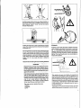
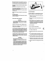
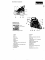
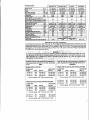
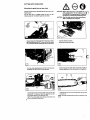
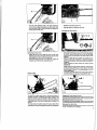
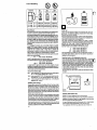
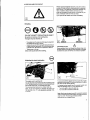
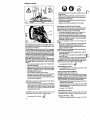
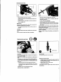
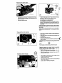
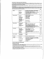
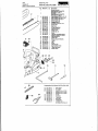
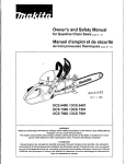
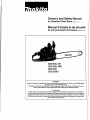
Owner’s and Safety Manual
for Gasoline Chain Saws (page 2 - 31)
Manuel d’emploi et de securite
de tronGonneuses thermiques (page 32 - 61)
DCS 430,431
DCS 520,520i
DCS 540
DCS 5200i
WARNING!
Read and understand this Manual. Always follow safety precautions in the Owner’s and Safety Manual.
Improper use can cause serious injury!
The engine exhaust from this product contains chemicals known to the State of California to cause
cancer, birth defects or other reproductive harm. Presepe this Manual carefully!
AlTENTlONl
Suivez toujours les conseils de skurite du present manuel d’emploi et de securite. Une utilisation
incorrecte de la tronqonneuse peut entrainer des blessures graves! Conservez avec soin ce manuel!
Les gaz d’echappement emis par ce produit contiennent des produits chimiques connus par I’Etat de
Californie pour provoquer le cancer, des defauts de naissance ou autres dommages de reproduction.
Lisez et comprenez ce manuel.
WARNING I
Careless or improper use of this product can cause serious or even fatal injury.
Before operating a chain saw or other MAKITA products it is important that you read, fully understand and
carefully follow the instructionsoutlined in this owners manual. Kickback may cause severe or fatal injury and.
is one of many potential dangers in operating a chain saw. Kickback and other safety related precautions are
described in detail within this owners manual. Additional owners manuals are available from MAKITA U.S.A.,
INC., 149304 Northam Street, La Mirada, CA 90638-5753, USA, Telephone: (714) 522 80 88 and MAKITA
CANADA INC.,1950 Forbes Street, Whitby, Ontario, L1N 787, Canada, Telephone: (905) 571 22 00.
4'1
.
This product complies with: American National Standard Institute B 175.1-1991 chain saw safety standard.
Canadian Standards Association
262.1-95 chain saw safety standard.
262.3-96 chain saw kickback standard.
Society of Automotive Engineers
SAEJ 335-Jun 95 ,Multiposition small
engine exhaust system fire ignition
suppression"
1
With the purchase of this chain saw you have chosen a German quality product. Important instructions for the
assembly and operation of this saw are given in this manual. For your own safety, we ask you to read the accident
prevention instructions very carefully before putting your chain saw into operation, as incorrect handling can,
despite all precautions, lead to accidents. With a little care and attention you will have good service and lasting
satisfaction from this first-rate product. The following industrial property rights apply: US 4465440, US 5411382,
EP 0236858, EP 0560201, GBM 8710075, GBM 8809928, GBM 9203378, GEM 29616652.
,
.
DCS 430, DCS 431, DCS 520, DCS 5201, DCS 540, DCS 5200i
c
Contents
Page
Contents
Delivery inventory
Symbols
Safety precautions
Denomination of components
Technical data
Approved bar and chain combinations
Mounting the guide bar and saw chain
Chain brake
Fuel I Refuelling
Adjusting the chain lubrication
Starting the engine
Stopping the engine
Checking the chain brake
Checking the chain lubrication
Adjusting the carburetor
Working in winter
3
3
4-15
16
17
17
18-19
19
20-21
21
22
22
23
23
23
24
24-25
Sharpening the saw chain
Cleaning the guide bar
25
Cleaning the brake band and sprocket interior 26
Replacing the saw chain
26
Replacing the suction head
26
Replacing I cleaning the spark arrester screen 26
Cleaning the air filter
27
Replacing the spark plug
27
Replacing the starter cable
28
Replacing the return spring
28
Mounting the fan housing
28
Instructions for daily and periodic maintenance 29
29-30
Service, spare parts and guarantee
Troubleshooting
30
Extract from the spare parts !ist
31
Adress list
62
Page
The MAKITA DCS 430, DCS 431, DCS 520, DCS 520i, DCS 540, DCS 5200i will be delivered in a protective
cardboard box to prevent transport damage. Cardboard is a basic raw material and is consequently reuseable or
suitable for recycling (waste paper recycling).
2
- .
.
,'
1
Delivery inventory
4
I
2-
I ’I
I
1 Chainsaw
2 Sawchain
6
5
7
3 Guidebar
4 Chain protection cover
5 Universal wrench
6 &Wrench
7 Screw driver for carburetor adjustment
(only in delivery for model 5200i)
8 Owner’s and Safety Manual (not shown)
In case one of the parts listed should not be included in the
delivery inventory, please consult your sales agent.
Symbols
You will notice the following symbols on the chain saw and in the Owner’s and Safety Manual:~
Read instruction manual
and follow the warning- and
safety precautions!
Stop engine!
Particular care and caution!
Wear protective gloves!
Forbidden!
Chain brake
Wear protective helmet, eye
and ear protection!
Caution, kickback!
Fuel and oil mixture
No smoking!
Carburetor adjustment
No open fire!
Chain oil filUoil pump
OnlOff (UO) switch
Working in winter
Press starting valve
-
First aid
Engine manual start
Choke lever
(Further
@
Recycling
symbols
see page 5.
3
Safety precautions for chain saw operators
Additional safety precautions
While operating the chain saw please observe the
following rules:
a)
Contact of the guide bar nose with any object
should be avoided.
b)
Tip contact may cause the guide bar to move
suddenly upward and backward, which may
cause serious or fatal injury.
Always operate the chain saw with both hands.
c)
The following additional safety precautions should be .
observedby all users of chain saws:
1. Do not operate a chain saw when you are fatigued.
manual. Failure to follow instructionscould result
in serious injury. It is recommended to lend the
chain saw only to people who are experlenced in
working with chain saws. Always hand over the
Owner‘s and Safety Manual.
WARNING!
Tbis chain saw k capable of severe kickback that
could resultin serious injuryto the operator. Do not
operate this chain saw unless you have
extraordinary cutting needsand experience inand
special training for dealing with kickback Chain
saws with significantlvreduced kickback wtential
are available.
2. Use safety footwear; snug-fitting clothing;
protective gloves: and eye, hearing, and head
protection devices.
3. Use caution when handling fuel. Move the chain
saw at least 10 feet (3 m) from the fueling point
before starting the engine.
4. Do not allow other persons to be near the chain
saw when starting or cutting with the chain saw.
Keep bystanders and animals out of the work
area.
*
5. Do not start cutting until you have a clear work
.
area, secure footing, and a planned retreat path
from the falling tree.
6. Keep all parts of your body away from the saw
chain when the engine is running.
7. Before you start the engine, make sure that the
saw chain is not contacting anything.
8. Carry the chain’sawwith the engine stopped, the
guide bar and saw chain to the rear, and the
muffler away from your body. -
-
9.
Kickback may occur when the no
guide bar touches an object, or w
closesin and pinchesthe saw chain
ntact may abruptly stop th
me cases may cause a l i i
ction,WkingtheguIdebar
user, or push the guide b
reduce the risk of a kckbadc and potential injury.
With a-basic understandina of kickback. vou
can reduceor eliminatethee7ementot surpise.
It is a sudden surprise that contributes to
acciden
Keep a
hands, your right hand on the rear grip and
your left handon the tubular handle, when the
engine is running. Use a firm grip with thumbs
and fingers encirclingthe chain saw handles.
A firm grip can neutralize kickback and help
you maintain control of the saw. Don’t let go!
C. Make sure that the area in which you are
cutting is free from obstructions. Do not let the
nose of the guide bar contact the log, branch,
or any other obstructions which could be hit
while you are operating the saw.
D. Do not overreachor cut aboveshoulder height.
E. Follow manufacturer‘s sharpening and maintenance instructionsforthesaw chain.
F. Only use replacement bars and chains specified by the manufactureror the equivalent.
4
Do not operate a chain saw that is damaged, is
improperly adjusted, or is not completely and
securely assembled. Be sure that the saw chain
stops moving when the throttle control trigger is
released.
10. Shut off the engine before setting it down.
11. Use extreme caution when cutting small s i z e c
brushand saplings because slender material may
catch the saw chain and be whipped towardyou
or pull you off balance.
12. When cutting a limb that is under tension be alert
for springback so that you will not be struck when
the tension on the wood fibers is released.
13. Keep the handles dry, clean, and free of oil or fuel
mixture.
14. Operate the chain saw only in well-ventilated
areas.
15. Do not operate a chain saw in a tree unless you
have been specifically trained to do so,
16. All chain saw service, other than the items listed in
the owner’s manual maintenance instructions,
should be performed by MAKlTA . (For example,
if improper tools are used to remove the flywheel
or if an improper tool is used to hold the flywheel
in orderto remove the clutch structural damage to
the flywheel could occur and could subsequently
cause the flywheel to burst.)
17 When transporting your chain saw, use the chain
protectioncover.
18. Low kickback bars and low kickback chains are
designed to reduce the risk of kickback injury. Ask
your MAKITA dealer about these devices.
’’
Maximum Computed Kickback Angle
(CKA)' without using the chain brake when
using the recommended bar and chain
combinations (In this example the CKAis 45").
General Safety Precautions
The use of any chain saw may be hazardous. At full
throttle chain speed can reach 45 mph (20 m/s).It is
importantthat you read; fully understand and observe
the following safety precautions and warnings. Read
the owner's manual and the safety instructions
periodically.
Maximumcomputed Kickback Angle
(CKA)' with using the chain brake when
using the recommended bar and chain
combinations (In this example me CKA is 40").
Contact of the guide bar tip with
any object should be avoided!
Tip contact may cause the guide
bar to move suddenly upward
and backward, which may cause
serious injury!
gerous. Careless or improper use of any chain saw
may cause serious or f
Haveyour MAKlTA dealer show you how to operate
your chain saw. Observe all applicable local safety
regulations, standards and ordinances.
Always use two hands when
operating the chain saw!
c2@
X
.
~
~
-
~
Reduced Kickback Bar and
Chaincombinationthat has been
evaluated with the power head
to achieve kickback Drotection
(according to ANSI 'and CSA
standards).
The Computed Kickback Angle is a calculatedvalue
from eneraies measured on a test bench.lt is mt the
angle of tbe guide bar moved upward in caseof a
KICKBACK.
The operator
Physical Condition
You must be in good physical condition and mental
health and not under the influence of any substance
(drugs, alcohol), which might impair vision, dexterity
or judgment.
fuel tank to 7/8 th full (see storing the saw).
not lend your chain saw without this owner's
nual. Be sure that anyone usinn your saw unProper use of a chain
1. the operator
2 the saw
3.the use of the
Discription of symbols used on chain
saws:
Z 62.1 -95and
Z 62.3-96
Compliance with
CSA -Standards
ANSI B175.1-1991
Compliance with
ANSI -Standards
Class 1A
@
Chain Saw list.ed in accordance with
45M6 Amencan,National Standard Safety
S ecificationsfor Gasoline Powered
saws (ANSI B 175.1-1991).
rain
Prolongeduse of chain saws exposingthe operator
to vibrations m a y produce Whitefinger disease
(Raynaud's phenomenon). This phenomenon
reduces the hand's ability to feel and regulate
temperature, produces numbness and buming
sensations and may cause nerve and circulation
damage and tissue necrosis.
Alt MANTA saws are therefore provided with an
antivibration system which is essential for those
using chain saws on a regular or sustained basis.
Antivibration systems do not guarantee that you will
not sustain Whiefinger disesase, however, they
reduce this danger considerably. Nevertheless,
continual and regular users should observe their
hands and fingers and in case af any abnormal
symptoms, seek m e d i i advice immediately.
5
Proper clothing
The saw
Clothing must be sturdy and snug-fitting, but allow
complete freedom of movement. Avoid loose-fitting
jackets, scarfs, neckties,jewelry, flared or cuffed pants,
or anything that could become entangled with the saw
or brush. Wear overalls or jeans with a reinforced
cutting resistant insert (fig. 3).
Parts of the chain saw: illustrationsand description of
parts see page 16.
Protect your hands with gloves when handling saw
and saw chain. Heavy-duty, nonslip gloves improve
your grip and protect your hands.
WARNING !
Never modify a chain saw in any way. Only
attachments supplied by MAKITA or expressly
approvedby MAKITA for use with the specific saw
are authorized.
WARNING !
0
Bow guidebarssubstantially increasethe potential
for kickback and severe or fatal injury due to the
greater kickback zone of the bow design. Bow
guide bars are not recommended for use on
MAKITA chain saws nor are they approved by the
ANSI B 175.1-1991 chain saw safety standard.
-'
The use of the saw
Transporting the chain saw
own or carrying it. Carryinga chain saw with the
en-gine Nnningisextremelydangerws.Accidental
Good footing is most important in chain saw worl
Wear sturdy boots with nonslip soles. Steel-toedsafety
boots are recommended.
Proper eye protection is a must. Non-fogging. vented
goggles and a face screen is recommended. Their
use reduces the risk of eye and facial injury.
Wear an approved safety hard hat to protect your
head. Chain saw noise may damage your hearing.
Always wear noise protection equipment (ear plugs
or ear muffs) to protect your hearing.
Continual and regular users should have their
hearing checked regularly.
Wear protective helmet,
eye and ear protection
6
By hand: When carrying your saw by hand, the
engine must be stopped and thesaw must be in the
proper position.
The chain protection cover should be over the
chain and the guide bar must point backwards.
When carryingyour saw the bar should be behind
you (fig. 4).
By vehicle: When transportingin a vehicle, keep
chainandbarcoveredwiththechainguard.Properly
secure your saw to prevent turnover, fuel spillage
and damage to the saw. Make sure the saw in not
exposed to heat or sparks.
,
Chain saw operating instructions
Wipe off any spilled fuel before starting your saw and
check for leakage.
For assembly follow the procedure in the appropriate
section "MountingGuide Barand Chain"of this manual.
MAKITA chain, guide bar and sprocket must match
each other (see the appropriate section inthis manual).
Check for fuel leakage while refueling and during
operation. If fuel or oil leakage is found, do not start or
run the engine until leak is fixed and spilled fuel has
been wiped away. Clothing with fuel on it has to be
changed immediately (this is a danger to your life!).
Avoid skin contact with fuel. Never loosen or remove
the cap of the fuel tank while the engine is running.
WARNING!
Propertensionof the chain is extremely important.
In order to avoid false setting the tensioning
pr0CedUre must be followed as described in this
manual. Always make sure the hexagonal nut@)
for the sprocket guard is (are) tightened securely
after tensioning the chain. Check chain tension
once more after having tightened the nuts and
thereafter at regularintervals (alwaysbeforestarting
to work). If the chain becomes loose while cutting,
shut off the engine and then tighten. Never try to
tighten the chain while the engine is running!
Starting
Do not drop start. This method is very dangerous because you may lose control of the saw (fig. 6).
L
Fueling
Your MAKITA saw uses on oil-gasolinemixture for fuel
(see chapter "Fuel" of this manual).
5
6a
Place the chain saw on firm ground or other solid
surface in an open area. Maintaina good balance and
secure footing. Place your right foot through the rear
handle opening and firmly grasp the front handle with
your left hand (fig. sa).
extreme caution when handling gasoline or fuel
mix. Do-not smoke or bring any sparks or flame
630
Fueling instructions
Fuel your chain saw in well ventilated areas or outdoors. Always shut off the engine and allow it to cool
before refueling. Select bare ground for fueling and
move the chain saw at least 10 feet (3m) from fueling
spot before starting the engine (fig. 5a).
I
a
I
5a
Be absolutely sure that guide bar and chain are clear
of you or all other obstructions and objects, including
the ground, because when the engine starts in semithrottle position, engine speed will be fast enough for
the clutch to engage the sprocket and turn the chain
which may cause a kickback.
Never attempt to start the saw when the guide bar is in
a cut or kerf.
When you pull the starter grip, don't wrap the starter
rope around your hands. Do not allow the grip to snap
back, but guide the starter rope slowly back to permit
the rope to rewind properly. Failure to follow this
procedure may result in injury to hand or fingers and
may damage the starter mechanism.
7
Important adjustments
Wrap your fingers tightly around the handles, keeping
the handlescradled betweenyour thumb andforefinger
(fig. 7). With your hands in this position, you can best
oppose and absorb the push, pull and kickback forces
of your saw without having it slip out of your grip (see
section of reactive forces). Make sure your chain saw
handle and grip are in good condition and free of
moisture, pitch, oil or grease.
WARNING1
At correct idle speed, chain should not tum. For directions to adjust idle speed, see the appropriate
section of this instruction manual.
Do not use a saw with incorrect idle speed adjustment. Adjust the idle speed yourself according to
the appropriate section of this manual.
Always start a cut with the chain running at full speed
and the spike bar in contact with the wood.
p
,
’
Have your MAKITA dealer check your saw and
make proper adjustments or repairs.
WARNING!
Check the saw chaintension frequently, especially
just after installing a new chain. New chains may
stretch more during their initial use. A properly adjusted saw chain can be pulled freely around the
guide bar by hand without sagging. Always stop
the engine and wear gloves when checking or
adjustingthe chain tension.
Never use the saw with one hand. You cannot
control reactive forces (see pages 9 to 11) and
may lose control of the saw.
,.
Working conditions
Operate your chain saw only outdoors. Operate the
saw under good visibility and daylight conditions only.
(rain, snow, ice). Putoff the workwhenthe weather
is windy, stormy or rainfall is heavy. Clear the area
ks &d watch out for holes or ditches.
Cutting instructions
Always hold the saw firmly with both hands when the
engine is running. Place your left hand on the tubular
handle and your right hand on grip and throttle lever.
Left-handers should follow these instructions too.
designed for pryingor shoveling away limbs, roots
or other objects.
I
When sawing, make sure that the saw chain does
not touch any foreign materials such as rocks,
nailsandthe like (fig. 8). Such objectsmay be flung
off, damage the saw chain or cause the saw to
kickback.
J
In order to keep controlof your saw, always maintain a
firmfoothold.Neverworkonaladder,inatreeoronany
other insecure support. Never use the saw above
shoulder height (fig. 9).
Positionthe chain saw in such a way that your body is
clear of the cutting attachment whenever the engine is
running(fig. 10).
Don't put pressure on the saw when reaching the end
of a cut. The pressure may cause the bar and rota!ing
chain to pop out of the cut or kerf, goout of control and
strike the operator or some other object. If the rotating
chain strikes some other object a reactive force (see
pages 10 to 12 ) may cause the chain to strike the
operator.
Kickback
Kickback occurs when the upper quadrant of the bar
nose contacts a solid object in the wood or is pinched
(fig. 11). The reactionof the cutting force of the chain
causesa rotationalforce of the chain saw inthe direction
opposite tothe chain movement, mainly in the plane of
the bar. This may fling the bar in an uncontrolled arc
towards the operator.
Reactiveforces during the cut, including kickback
kickback, pushback and pull-in. Reactive forces
can be dangerous1In any chain saw, the powerful
force usedto cut wood can be reve
against the operator).
If the rotatingchain is suddenly stopped by contact
with any solid object like a log or branch or is
pinched, the reactive forces instantlyoccur.These
reactive forces may result in loss of control which
may, in turn, cause serious or fatal injury. An
understanding of the causes of these reactive
forces may help you avoid loss of control.
The most common reactive forces are
kickback,
pushback,
pull-in.
-
Yw-\-
12
This reaction can occur in a fraction of a second and
under some circumstances, cause the guide bar and
chain to strike the operator with enough force to cause
severe or fatal injury. It may also occur during limbing.
It also occurs when the noseof the guide bar is pinched
unexpectedly, unintentionallycontacts solid material
in the wood (fig.12) or is incorrectly used to begin a
plunge or boring cut.
Thegreatertheforceofthe kickbackreaction,the more
difficult it becomesforthe operator to controlthe saw.
9
Many factors influence the occurence and force of
the kickback reaction. The type of bar and saw chain
you use is a factor in the force of the kickback reaction.
The speed of contact at which the cutter contacts
theobject.
Kickback force increase with the rate of impact..
The contact angle between the nose of the bar
and the foreign object (fig. 11).
Kickback is most pronounced in the upper quadrant
of the bar nose.
MAKITA chain types are designed to reduce kickback
forces.
The depth gauges:
Improper lowering of the depth gauges also increases
the risk of a kickback.
c"_..
I
13
To avoid kickback
The best protection from personal-injury that may
result from kickback is to avoid kickback situations:
1. Hold the chain saw firmly with both hands and
maintain a secure grip.
2. Be aware of the location of the guide bar nose at
all times.
Saw chain cutter sharpness:
WARNING!
A dull improperly sharpened chain may increase
the risk of kickback Always cut with a properfy
sharpened chain.
-1
*
3. Never bring the nose of the guide bar in contact
with any object. Do not cut limbs with the nose of
the guide bar. Be especially careful with small,
tough limbs, small size brush and saplings which
may easily catch the chain.
Devices for reducing the risk of kickback injury
4. Don't overreach.
MAKITA have developed a special chain brake to
reduce the risk of kickbacks.
5. Don't cut above shoulder height.
This chain brake increases the safety factor on the
job, e.g. when the saw suddenly bucks upwards the
chain stops rotating within a fraction of a second. A
deflectionguard on the disengaging lever of the chain
brake and a scoop rear handle ensure that the operator's hands are fully protected at all times.
6. Begin cutting and continue at full throttle.
Kickback tendency increases as the radius or size of
the guide bar nose increases. MAKITA have developed guide bars with small nose radius, to reduce the
kickback tendency.
9. Do not attempt plunge cuts (see page 13) if you
7. Cut onti one tog at a time.
8. Use extreme caution when re-entering a previous
cut.
are not experiencedwith these cutting techniques.
10. Be alert for shifting of the log or other forces that
may cause the cut to close and pinch the chain.
No chain brake prevents ki
These brakes are designed only to stop the chain,
if activated.
To ensure a proper operation of the chain brake, it
must be properly maintained. Furthermore, there
must be asufficient distance betweenthe operator
and the bar to ensure that the chain brake has
sufficienttime to activate and stop the chain before
potential contact with the operator.
10
11. Maintainsaw chain properly. Cut with a correctly
sharpened, properly tensioned chain at all times.
12. Stand to the side of the cutting path of the chain
saw.
Pushback:
To avoid pull-in
Pushback occurs when the chain on the top of the bar
is suddenly stopped when it is pinched, caught or
encountersa foreign object in the wood. The reaction
of the chain drives the saw straight back toward the
operator causing loss of saw control. Pushback frequently occurs when the top of the bar is used for
cutting (fig. 14).
1. Always start a cut with the chain rotating at full
speed and the spike bar in contact with the wood.
2. Pull-in may also be prevented by using plastic
wedges to open the kerf or cut.
Cutting techniques
Felling
Felling is cutting down a tree.
Before felling a tree, consider carefully all conditions
which may affect the direction of fall, including:
14
To avoid pushback
The intended direction of the fall.
The neutral lean of the tree.
Any unusually heavy limb structure.
Surrounding trees and obstacles.
The wind direction and speed.
1. Be alert to forces or situations that may cauE
material to pinch the top of the chain.
'
2. Do not cut more than one log at a time.
3. Do not twist the saw when withdrawing the bar
from a plunge cut or under buck cut (figures 25 to
27 and 33, pages 13 and 15),because the chain
can pinch.
Pull-in:
WARNING!
Always observe the general condition of the tree.
Look for decay and rot in the trunk. If it U rotfed
_
vibrate loose and fall on the operator. When.fellina
on aslope, the operator should stand on the up-hi
Pull-in occurs when the chain on the bottom of the bar
is suddenly stopped. The chain on the bottom of the
bar stops when it is pinched, caught or encounters a
foreign object in the wood (see fig. 15). The reactionof
the chain pulls the saw forward, causing the operator
to lose control.
Pull-in frequently occurs when the spike bar of the
saw is not held securely against the tree or limb and
when the chain is not rotating at full speed before it
contacts the wood.
When felling in the vicinity of roads, railways and
power lines, etc., take extra precautions (see fig.
16). Inform the police, u t i l i company or railway
authority before beginning to cut.
15
WARNING!
Use extremecautionwhen cuttingsmall size brush
and saplings which may easily catch the chain and
pull you off balance.
11
,
-
.- - -
---1
I
1
I'
'
I
-
--____---
.
= cutting down area
I
When felling, maintain a distance of at least 2 1/2 tree
lengths from the nearest person (see fig. 17).
If the tree has large buttress roots, cut into the largest
buttresses vertically first (horizontally next) and remove (fig. 20).
.
Note:
The noise of your engine may drown any waming call.
Felling instructions:
'
I
p
lis $1
+
Direction of fall
18
First clear the tree base and work area from interfering limbs and brush and clean its lower portion an
axe (see fig. 18).
\I/r
w
I
19 JI
Then, establish a path of escape and remove all
obstacles. This pathshould be opposite to the planned
direction of the fall of the tree and at a 45" angle (fig.
19). An alternate path must also be selected. Place all
tools and equipment a safe distance away from the
tree, but not on the escape path.
12
I
Felling notch I
I Hinge
23
I
Then, determine the placement of the felling notch
(fig. 21). The felling notch when properly placed determines the direction in which the tree will fall. It is
made perpendicular to the line of fall and should be as
close to the ground as possible. Cut the felling notch
to a depth of about one-fifthto one-fourth of the trunk
diameter (fig. 22). It should be in no case higher than
it is deep. Make the felling notch very carefully.
'
Begin the felling cut slighty higher than the felling
notch and on the opposite side of the tree (fig. 22).
Then cut horizontally through towards the felling notch.
Apply the chain saw with its spikes directly behind the
uncut portion of wood and cut toward the notch (fig.
23). Leave approximately 1/10 of the tree diameter
uncut! This is the hinge (fig.23). Do not cut through the
hinge because you could lose control of the direction
of the fall. Drive wedges into the felling cut where
necessary to control the direction of the fall. Wedges
should be of wood, light alloy or plastic never of steel,
which can cause kickback and damage to the chain.
-
Plunge-Cut Method
Timber having a diameter more than twice the length
of the guide bar reauires the use of the plunge-cut
method before making the felling cut.
First, cut a large, wide notch. Make a plunge cut in the
center of the notch.
The plunge cut is made with the guide bar nose. Begin
the plunge cut by applying the lower portion of the
guide bar nose to the tree at an angle (fig. 25). Cut until
depth of the kerf is about the same as the width of the
guide bar (fig. 26). Next, align the saw in the direction
Always keep to the side of the falling tree. When the
tree starts to fall, shut off the engine, withdraw the bar
and walk away on the pre-planned escape path.
Watch out for falling limbs.
WARNING!
Be ememelycarefulwith partiallyfallen trees which
are poorly supported.
When the tree hangs or for some other reasondoes
not fall completely, set the saw aside and pull the
tree down with a cable winch, block and tackle or
~~
in which the recess is to be cut. With the saw at full
throttle, insert the guide bar in the trunk (fig. 27).
Enlargethe plunge cut as shown in illustration(fig. 28)
Sectioning Method
length of the guide bar requires use of either the
sectioning or plunge-cut method. These methods
are extremely dangerous becausethey involve the
use of the nose of the guide bar and can result in
kickback. Only property traine
24
~
For the sectioning method (fig. 24) make the first cut
with the guide bar fanning in toward the hinge. Then,
using the bumper spike as a pivot, reposition the saw
for the next cut. Avoid repositioningthe saw more than
necessary. When repositioning for the next cut, keep
the guide bar fully engaged in the kerf to keep the
felling cut straight. If the saw begins to pinch, insert a
wedge to open the cut. On the last cut, do not cut
the hinge.
28
13
Bucking
Bucking is cutting a log into sections.
29
WARNING!
There is an extreme danger of kickback at this
point. Extra caution must be taken to maintain
control of the saw. To make the felling cut, follow
the sectioning method described previously (fig.
29). If you are inexperienced with a chain saw
plunge-cutting should not be attempted. Seek the
help of a professional.
WARNING!
1. When bucking, do not stand on the log. Make
sure the log will not roll down-hill. If on a slope,
stand on the uphill side of the log (seefig. 31).
Watch out for rolling logs.
Limbing
Limbing is removing the branches from a fallen tree.
ARNING!
There is an extreme danger of kickback during the
limbingoperation. Do not workwith the nose of the
bar. Be extremely cautious and avoid contacting
the log or other limbswith the noseof the guide bar.
or the log may roll.
I
1
Start limbingby leavingthe lower limbs to support
the log off the ground (fig. 30). Always cut fromthe
top of the limb. Do not underbuck freely hanging
limbs. A pinch may result or the limb may fall,
causing loss of control. If a pinchoccurs, stop the
engine and remove the saw, by lifting the limb.
WARNING!
Be extremely cautious when cutting limbs under
tension. The limbs could spring back toward the
operator and cause loss of control of the saw or
injury to the operator.
14
WARNING!
4. Whencuttingsmalllogs,useasawhorse(fig.32).
Never permit another perkon to hold the log.
Never hold the log with your leg or foot.
Maintenance and Repair
Never operate a chain saw that is damaged, improperly adjusted or not completely or securely assembled.
Follow the maintenance and repair instructionsin the
appropriate section of this manual.
WARNING !
li
3:
1
I
2. Cross cut
Always stop the engine and make sure that the
chain is stopped before commencing any maintenance or repair work or cleaning the saw. Do not
attempt any maintenance or repair work not described in this manual. Have such work performed
by your MAKITA service shop only.
Maintaining and storing the saw
I-
Keep the chain, bar and sprocket clean and lubricated;
replace worn sprockets or chains.
ire special attention to
stress on the log (seefig. 33,34).The bucking
Keep the chain sharp. You can spot a dull chain when
easy-to-cut wood becomes hardto cut and burn marks
appear on the wood.
Keep the chain at proper tension. Tighten all nuts,
bolts and screws except the carburetor adjustment
screws after each use.
Keep spark plug and wire connection tight and clean.
Store saws in a high or locked place, away from
children.
WARNING!
6. Onlyproperlytrainedprofession
in an area where the logs, limbs and roots are
tangled (i.e. a blowdown area, fig. 35). Working in blowdown areas is e
ous.
NING!
7. Drag the logs into a clear area before cutting.
Pull out exposed and cleared logs first.
Denomination of components
12
10
9
8
Identification plate
(example model DCS 5200i)
Indicate when ordering spare parts!
24
23 22
18
21
1 Handle
13 Guide bar
2 Choke
14 Chain
3 Filter cover
15 Hand guard (release for chain brake)
4 Tubular handle
16 Starter grip
5 Muffler
17 Adjusting screws "S-L-H" for carburetor
6 Retaining nuts
18 VSTOP-switch
7 Spike bar
19 Stop knob for halfway throttle
(toothed stop for holding saw steady against wood)
20 Safety locking button
8 Chain catcher
21 Throttle lever
9 Adjusting screw for oil pump (bottom side)
22 Fuel tank cap
10 Sprocket guard
23 Fan housing with starting assembly
11 Identification plate
24 Oil tank cap
12 Hand guard
25 Starting valve (only DCS 431)
16
Technical data
DCS 430 I 431
I DCS 520 I5201
DCS540
I
DCS 52001
Approved bar and chain combinations
"Low-kickback saw chain is a chain which has met the kickback performance requirements of ANSI B 175.1-1991
(Amencan NationalStandardfor PowerTools-Gasoline-PoweredChain Saws-Safety Requirements)when testedon the
representative sample of chain saws below 3.8 c.i.d. specifed in ANSI B 175.1-1991".The approved bar and chain
combinations are low kickback chains according to ANSI 6 175.1-1991and also meet the kickback requirements of
CSA 262.3-96for chains saws below 80 cm3.
designated as 'low kic
_
_
_
~
iuide bar and saw chain combinationsmeeting kicklack requirements of ANSI B 175.1-1991 for the use
n the
USA
h i d e bar and saw chain combinations meeting kick,ack requirementsof CSA 262.3-96 for the use in
Aodels DCS 430, DCS 431
Uodels DCS 430~431,520,5201,540and DCS 5200i
XJlDE BAR
ength
GUIDE BAR
lenath
SAW CHAIN
pitch partno.
part no.
523 085 664
.325" 445 038 631
15' (38cm)
523 085 666
16"(40cm) .325" 445 040 631
523 085 672
.325" 445 045 631
18' (45cm)
Drive link gauge: .058", Chain sprocket: 8 teeth
CANADA
pitch
part no.
SAW CHAIN
part no.
523 085 664
15"(38cm) .325" 445 038 631
523 085 666
16"(40cm) .325" 445 040 631
523 085 672
18"(45cm) .325" 445 045 631
Drive link gauge: .058",Chain sprocket: 8 teeth
15"(38cm)
Uodels DCS 520, DCS 5201, DCS 540, DCS 5200i
GUIDE BAR
length
pitch
part no.
SAW CHAIN
part no.
3/8"
443 038 651
522 094 656
443 045 651
522 094 664
18"(45cm) 3/8"
443 053 651
522 094 672
21' (53cm) 3/8"
Drive link gauge: .058', Chain sprocket: 7 teeth
523 085 664
15" (38cm) .325' 445 038 631
523 085 666
16' (40cm) .325' 445 040 631
523 085 672
18' (45cm) .325' 445 045 631
Drive link gauge: .058',Chain sprocket: 8 teeth
18" (45cm) 3/8"
443 045 661
523 102 664
21 ' (53cm) 318"
443 053 661
523 102 672
Drive link gauge: . O W ,Chain sprocket: 7 teeth
17
PUlTlNG INTO OPERATION
Mounting the guide bar and saw chain
Use the universalwrench delivered with the chain saw for the
following work.
Put the chain saw on a stable surface and carry out the
following steps for mounting the guide bar and chain:
CAUTION: Before doing any work on the guide bar or
chain. M y s switch off the engine and pull
the plug cap off the spark plug (see 'Replacing
thespark plug"). Alwayswear protectivegloves!
CAUTION: Start the chain saw only after having assem-
.
bled it completely and inspected!
-
Always release the chain brake before removingor replacing the sprocket guard (W4). To do so.pull the hand guard
( N l )towards the tubular handle (N2) until you feel it catch.
-
Turn the chain adjusting screw.(C/6) to the left (counterclockwise) until the pin (Cn) is at the left stop.
-
Unscrew retainingnuts (813).
Pull off the sprocket guard (814).
_.-
-
Positionthe guide bar (We).Make sure that the pin (D19)of
the chain tightener is in the hofe (circled) on the guide bar.
10
-
18
Lift the chain (U10)
over the clutch drum and onto the
sprocket ( V l l ) .Usingyour right hand, guide the chain into
the top guide groove on the guide bar (W8).
NOTE: The cutting edges along the top of the chain must
point in the direction of the arrow!
-
12
I
Lead the chain (F/lO) around the sprocket nose (F/12)of
the guide bar.
NOTE: The chain should be easy to pull in the direction of the
arrow.
El
-
Turn the chain tightener (W6) to the right (clockwise)
until the chain engagesthe guide groove of the bottom side
of the bar (see circle). Press the guide bar against the
housing with your left hand.
Tightening the saw chain
Slightly lift the end of the guide bar and turn the chain
adjusting screw (116) to the right (clockwise) until the chain
rests against the bottom side of the guide bar.
While still holding up the tip of the guide bar, tighten the
retaining nuts (W3)with the universal wrench.
-
-
-
4
3
Replace the sprocket guard (W4).
Manually tighten the retaining nuts (W3).
Checking the chain tension
-
The tension of the chain is correct if the chain rests against
the bottom side of the guide bar and can still be easily
turned by hand. While doing so the chain brake must be
released.
Every new chain has to be broken in for about 2 to 3
minutes. Ample chain lubrication is essential during this
period. After breaking in, check chain tension and adjust, if
necessary.
When checking the chain tension the engine must be
-
Chain brake
The MAKITA models comes with an inertia chain brake as
standard equipment. If kickback occurs due to contact of the
guidabar tip with wood (see SAFETY PRECAUTIONS), the
chain brake will stop the chain through inertia if the kickback is
sufficiently strong. The chain will stop within a fraction of a
second.
The chain brake Is installed to block the saw chain before
starting it and to stop it immediately in case of an emergency.
NOTE: Check the chain tension frequently chains tend to
get longer during use! If this is not done, there is a risk of the
chain jumping off the bar. It is recommendedto use 2-3
chains altematively.
In order to guarantee uniform wear of the guide bar the bar
should be turned over whenever replacing the chain.
Engaging the chain brake (braking)
If the kickback is strong enough the sudden acceleration of the
guide bar combined with the inertia of the hand guard (U3)
will
automatically actuate the chain brake.
To engage the chain brake manually, simply push the hand guard
(U3)forward(towardsthetipofthesaw)withyourlefthand(arrow 1).
Releasing the chain brake
Pull the hand guard (u3)
towards you (arrow 2) until you feel
it catch. The brake is now released.
Fuel I Refuelling
I
Gasoline
I
I
+
I
40:l
omer dl
1
@@
501
pJ
MAKITA a1
I
1OO:l
W K A oil
1
1.3nOr(3acm)
1.0 US-@. (3.71) 32nOr(94a)) 25nOr@OTt'l
2.5 U S - ~ I . (9.4 I) aonOrmcm) wn~r(iescm)~znozp~m
5.0 US-Wl. (18.9 I) lROIbZ(473aIFI 128IbZ(nScm) 6.4fbZ(189cm)
U
Chain oil
Use an oil with adhesive additive for lubricating the chain and
guide bar. The adhesive additive prevents the oil from being
flung off the chain too quickly.
We recommendthe use of chain oil which is bio-degradablein
order to protect the environment. The use of bio-degradableoil
may even be required by local regulations.
The chain oil BIOTOP sold by MAKITA is made of special
vegetable oils and is 100% bio-degradable.BIOTOP has been
granted the 'blue angel' (Blauer Umweltschutz-Engel) for
being particularly environment-friendly (RAL UZ 48).
BIOTOP chain oil is available in the following sizes:
order number 980 008 610
order number 980 008 61 1
order number 980 008 613
Biodegradableoil is stable only for a limited period of time. It
should be used within 2 years from the date of manufacture
(printed on the container).
1I
5I
20 I
Important note on bio-degradable chain oils:
Ifyou are not planning to use the saw again for an extend
period of time (longer than the expiration date of the chain oil)
empty the oil tank and put in a small amount of regular engine
oil (SAE 30),and then run the saw for a time. This is n&essary
to flush out all remaining bio-degradable oil from the oil tank,
oil-feed system, chain and guide bar, as many such oils tend
to leave sticky residues over time, which can cause damage
to the oil pump or other parts.
The next time you use the saw, fill the tank with BIOTOP chain
oil again.
T7
.
NEVER USE WASTE OIL
Waste oil is very dangerous for the environment.
Waste oil contains high amounts of carcinogenic substances.
Residues in waste oil result in a high degree of wear and tear
at the oil pump and the sawing device.
In case of damage caused by using waste oil or unappropriate
chain oil the product guarantee wit1 be null and void.
Your salesman will inform you about the use of chain oil.
c
AVOID SKIN AND EYE CONTACT
Mineral oil products degrease your skin. If your skin comes in
contact with these substances repeatedly and for an extended
period of time, it will desiccate. Various skin deseases may
result. In addition, allergic reactions are known to occur.
Eyes can be irritated by contact with oil. If oil comes into your
eyes, immediately wash them with clear water.
If your eyes are still irritated, see a doctor immediately!
Refuelling
FOLLOW THE SAFETY PRECAUTIONSON PAGE 7!
Be careful and cautious when handling fuels.
The engine must be switched off1
-
Thoroughly clean the area around the caps, to prevent dirt
from getting into the fuel or 08 tank.
- Unscrewthe cap and fill the tank with fuel (fueVoil mixture)
or chain oil as the case may be. Fill up to the bottom edge
of the filler neck. Be careful not to spill fuel or chain oil!
Tightly screw on the cap.
Clean screw cap and tank after refuelling.
-
Adjusting the chain lubrication
Lubricating the chain
During operation there must always be sufficient chain oil in
the chain-oil tank to provide good chain lubrication. One filling
is sufficient for about one half-hour of continuous operation.
W
The engine must be switched off.
You can adjust the oil pump feed rate with the adjusting screw
(F/l). The adjusting screw is locatedin the housingunderneath
the sprocket guard (F/2). It is accessible from below.
The oil pump comes factory-set to a medium feed rate.
Note: To set from minimum to maximum oil supply, turn
the adjusting screw (FI1 with adjustment markings) max.
a l/4-turn.
To ensure troublefree operation of the oil pump the oil guide
and the oil inlet bore in the guide
groove at the crankcase (W3)
bar (W4) must be cleaned regularly.
To change the feed quantity use the universal wrench and
adjust the adjusting screw (F/1) in the following way:
Turn to the right to reduce the feed rate.
Tum to the left to increase the feed rate.
-
Note: After the saw has been turned off it is normalfor residual
chain oil to drip from the oil feed system, the guide bar and the
constitute a defect!
chain for a time. This does
Place the saw on a suitable surface.
21
Starting the engine
-
Move at least 10 feet (3m) away from the place where you \ - ,
fuelled the saw.
Makesureyou have agoodfooting, and placethesaw on the
ground in such a way that the chain is not touching anything.
Engage the chain brake (lock).
Holdthe tubular handletightly wlth one hand and press the
chain saw to the ground.
Steady the rear handle by standing in the hand guard.
Cold-starting the DCS 520i and DCS 5200i:
The carburetors of these saws have a fuel-injection system
.
(injection carburetor) for cold starting (mixture enrichment).
These two cold-starting systems work differently.
Put the short-circuit ignition switch in the "I'position (Wl).
Pull out the choke (BE) (opens the injection valve).
half-wayand hold.
Depressthe half-throttlelock button (W3)
Depress the throttle (W4)and half-throttle lock button (W3)
all the way. Release the throttle it will now be held at
half-throttle by the lock button.
Note: If the temperature is below -15" C (5' F) start at full
throttle.
Slowly pull out the starter cable until you notice resistance
(the piston is positionedbefore the top dead center).
Now pull the starter Able with a fast and forceful movement
until you hear the first ignition.
CAUTION: Do not pull out the starter cable more than approx.
50 cm. and lead it back by hand.
Push in the choke (BM) when the engine starts, or after the
first audible ignitions.
- If the engine has not yet started, keep pulling the starter<:;
cable until it does.
As soon as the engine is running, press the throttle (W4)to rg
releasethe half-throttlelock(B/3), allowingtheengine to idle.
CAWION: As soon as the engine is started it must be put in
idle to prevent the chain brake from being damaged.
-
Cold-starting the DCS 430,431, DCS 520, DCS 540:
The carburetors of these saws have a choke valve for cold
starting (mixture enrichment).
To make it easier to start, the chain saw DCS 431 is equipped
with a semi-automatic starting valve (W5). Pushing this valve
in reduces the amount of compression effort needed, so that it
is easier to bring the engine up to starting speed when pulling
the starter cable. The highpressureincrease in the combustion
chamber that results from the first ignitions will automatically
close the starting valve (button pops back out).
Model DCS 430, DCS 520 do not have a startlng valve.
Starting and carburetor adjustment are as for model DCS
431 except without tho Instruction 'Push tho starting
valve".
Put the short-circuit ignition switch in the 'I' position (Ell).
Pull out the choke (812).
Depressthehalf-throttlelockbutton(W3)
half-way andhold.
Depress the throttle (814)and half-throttle lock button (en)
all the way. Release the throttle it will now be held at
half-throttle by the lock button.
Push the starting valve (815)(only DCS 431).
Slowly pull out the starter cable until you notice resistance
(the piston is positioned before the top dead center).
- Now pull the starter cable with a fast and forceful movement
until you hear the first ignition.
-
-
-
CAUTION: Do not pull out the starter cable more than approx.
50 cm. and lead it back by hand.
When you hear the first ignition, push the choke (BM) in.
Push the starting valve again (only DCS 431) and pull the
starter cable. As soon as the engine is running, press
the throttle (W4)to release the half-throttle lock (W3).
allowing the engine to idle.
-
-
-
-
-
-
-
Now release the chain brake.
Warm starting (all models):
-
&
As described above for cold starting, but without using
the choke (W2). Keep the choke in.
Starting under special conditions
(MAKITA DCS 520i and DCS 5200i only):
In conditions of high ambient temperature and when the engine
has been stopped for only a short,period following fulCload
operation, if afuel with alow boiling point is used (winter fuel). and
at high altitudesespecially,the heat couldprevent the enginefrom
starting immediately. If this happens, proceed as follows:
Pull out the choke (BE)and start the engine at half-throttle.
as described for cold starting.
- When the engine has started. release the chain brake
Immediately and gun the engine all the way several times
until it runs smoothly.
- Now push in the choke (812).
-
If the engine won't start:
CAUTION: As soon as the engine is started it must be put in
idle to prevent the chain brake from being damaged.
22
Now release the chain brake.
If the engine refuses to start even after a number of tries, check
the spark plug (seethe section on "Replacingthe spark plug").
Stopping the engine
-
@
Put the short-circuitingswitch (ell)in position "0"(STOP).
Checking the chain brake
IICI
Checking the chain lubrication
I
Do not work with the chain saw without flrst checking the
chain brake1
Start the engine as described(make sure you have a good
footing, and place the chain saw on the ground in such a
way that the guide bar is free of contact).
- Graspthe tubular handlefirmly with one hand and holdthe
grip with the other.
-With the engine runningat moderatespeed, pressthe hand
f
guard ((31) in the direction of the arrow
y
muntil the chain brakeengages. The chain should
stop immediately.
- Immediately release the throttle and release the chain
brake.
IMPORTANT: If the chain does not stop immediatelywhen
you test the chain brake, do NOT use the chain saw. Take
the chain saw-to a MAKITA senrice center for repair.
-
-
Never work with the chain saw withoute sufficient chain lubrication. Otherwisethe service life of the chain and guide barwill
be reduced. Beforestarting work check the oil level in the tank
and the oil feed.
Check the oil feed rate as described below:
Start the chain saw.
Hold the running chain saw approx. 6' (15 cm) above a
trunk or the ground (use an appropriate base).
If the lubrication is sufficient, you will see a light oil trace
because oil will be flung off the sawingdevice. Pay attention to
the direction the wind is blowing and avoid unnecessary
exposure to the oil spray!
-
-
Adjusting the carburetor
Important Information:
The carburetor of this tool is litted with limiter caps which restrict
the range of adjustment and prevents over-rich mixturesettings.
This ensures providing good engine power and efficient fuel
consumption. Before installingthe limiter caps, the manufacturer
performs the .Basic Adjustment" procedure.
Optimum perfomance can only be achieved if the carburetor Is adjusted correctly. For this work, which should be
cam'ed out by an expert, the engine must be warmed up and
the alr filter clean.
The carburetor has been adjusted by MAKITA on the basis of
abnosheric pressure conditionsat sea level. Other atmospheric
pressure conditions or the running-in process of a new engine
.
may require readjustment of the carburetor.
It is urgently recommended to use a revolution indicator (U1)
(order number 950 233 210) in order to achieve a correct
adjustmentof the carburetor. Adjust the carburetor using a 0.16"
(4 mm) screwdriver (u2,in assembly tool kit with 1 1 3 only).
The screwdrivershown (W2)(order number 944340 001) has
a molded-on lug to assist in adjustment.
Before adjusting the carburetor the engine must be warmed
up for a period of 3-5 min.
For adjusting the carburetor correctly the following steps
must be carried out:
1. Check adjustment
2. Start engine
3. Set idle speed
4. Adjust speed
5. Check idling speed
6. Check acceleration
7. Check max. speed or output
8. Repeat adjustment procedure starting with step 3, until
idling speed, m a . speed and acceleration are reached
with the adjustment made.
Adjustment instructions (step 1)
@
Before initial operation make sure that the adjusting screws
(H and L) have not been set in all the way. Limiter caps do not
protect the engine from leaning. Tum the two adjustingscrews
(H and L) counter-clockwiseas far as they will go.
Start the engine and let it warm up (step 2)
a+
Set idle speed (step 3)
If the chain tums when the engine is idling, unscrew the
throttle-valve stop screw (S) until the chain stops. If the
engine runs unevenly, screw the screw (S) back in.
Idling speed should be 2.500 rpm.
Adjust speed (output) (step 4)
Adjust the speed by adjustingthe mainjet screw (H) to 12.500
(DCS430,431,520) and 1 3 . W (DCS 520i. 540,5200i) rpm.
Check idle speed (item 5)
After havingadjustedthe max. speed ensurethe idle speed
is set to 2,500 rpm. (the chain must not turn). Use the idle
jetscrew(L)toregulateit.Turninthescrew (L) tospeed up,
and tum out the screw (L)to speed down the engine.
Check acceleration (item 6)
Now check the acceleration, i. e. the time necessary for
speeding up from idle speed !o max. speed. To do this,
press the throttle lever hard.
If the acceleration is too low, tum out the idle jet screw (L)
approx. 110 rotation.
-
-
-
-
-
23
Working in winter
,:
In order to prevent carburetor icing in conditionsof low temperature combined with high humidity. and in order to get up to
operating temperature faster in subfreezing temperatures.
heated air can be taken from the cylinder.
At temperatures above freezing the carburetor must NOT be
fed heated air.
Failure to follow these instructions can lead to damage
to the cylinder and piston!
c
-
I-
_-
I
_.
I
-
The snow filter (Wl, see "Accessories") prevents the
induction of powder snow. It is placed under the prefilter
(en).
-
Remove the filter cover and air filter (see'Cleaning the air
finer').
- To enable hot-air induction from the cylinder, remove the
plug (Nf)using the universal wrench.
NOTE
Keep the plug in thesaw's tool kit. You must put the plug back
in at temperatures above 0"C / 32" F.
Reinstall the air filter and filter cover.
NOTE:
Remove the snow filter before working at temperatures
above 0' C (32' F)I
When not in use, store the snow filter in the assembly tool
pouch.
-
MAINTENANCE
Sharpening the saw chain
@@
.030" (chain: 094,102 I W8")
CAUTION:
Before doing any work-on the guide bar or chain, a h y a
switch off the engine and pull the plug cap off the spark
plug (see 'Replacing the spark plug"). Always wear protective gloves!
I
The chain needs sharpening when:
The sawdust producedwhen sawingdamp wood looks like
wood flour.
The chain penetrates the wood only under great pressure.
The cutting edge is visibly damaged.
The saw is pulled to the left or right when sawing. This is
caused by uneven sharpening of the chain.
Important: Sharpen frequently, but without removing too
much metal!
Generally, 2 or 3 strokes of the file will be enough.
Have the chain resharpened at a service center when you
have already sharpened it yourself several times.
-
Proper sharpening:
CAUTION:
Use only chains and guide bars designed for this saw
(see the Extract from the spareparts list)!
All cutters must be of the same length (dimension a).
Cutters with different lengths result in rough running of the
chain and can cause cracks in the chain.
Minimumcutter length: 0.1 1' (3mm). Do not resharpenthe
chain when the minimum cutter length has been reached;
at this point, the chain must be replaced (see the Extract
from the spareparts list and 'Replacing the saw chain').
The depth of the cut is determined by the ditterence in
height between the depth limiter (round nose) and the
cutting edge.
The best results are obtained with a depth-limiter depth of
.025'(chain: 085 I 325")or . O W (chain: 094. 102 / 318').
CAUTION:
Excessive depth Increases
the risk of kickback!
24
--
Chain
Sharpening angle a
Front rake
085 (.325")
25"
60'
094.102 (38')
30"
05'
Files and how to work with them
-
Sharpen usinga special file holderwith a saw chain roundfile:
085 (.325')chain: File the first cutter half with a 4.5 mm dia.
round saw-chain file. then switch to a 4 mm dia. file.
094,102 (3/8')chain: Round saw-chain file 4.8 mm diameter.
Normal round files are not appropriate for this work. See
'Accessories' for the order number.
The file should cut only when pushed forwards (arrow). Lift
the file when leading it backwards.
First sharpen the shortest cutter. The lengthof this cutter is
then the standerd for all other cutters of the chain.
Always guide the file as in Fig. F shown.
-
-
-
-
-
The file holder makes file guidance easier. It is marked for
the correct a sharpening angle (keep the marks parallel
with the chain when filing, see illustration)and limits the Cut
depth to the correct 4/5 of the file diameter. See 'Accessories' for the order number.
-
-
After having sharpened the-chain,the height of the depth
limiter must be checked by means of a chain
. gauge. See
'Accessories' for the order number.
Correct even the smallest excess height with a special flat
file (H).See 'Accessories" for the order number.
Round off the front of the depth limiter (I).
Cleaning the guide bar
CAUTION:
Protective gloves must be worn.
Regularly inspect the bearing surfaces of the guide bar for
damage, and clean them with a suitable tool.
2!
Cleaning the brake band and sprocket interior
Replacing the saw chain
CAUTION:
Use only chains and guide bars designed for this saw (see
the Extract from the spare-parts list and page 17)!
C
I
'
I
1
2
\
I
4
CAUTION: Before doing any work on the guide bar or
chain, w y s switch off the engine and pull
the plug cap off the spark plug (see 'Replacing
the sparkplug'). Alwayswear protective gloves!
CAUTION: Start the chain saw only after having assembled i t completely and inspected!
-
Remove the sprocket guard (Nl) (See 'PUTTING INTO
OPERATION' figs. A and e).
Tum the chain tightener screw (M?)
to the left (counterclockwise) untii you feel resistance.
Remove the chain (N3)and guide bar (N4).
Clean the interior with a brush, in particularthe brake-band
area (AIS).
NOTE
Make sure that no residue or contaminants remain in the oil
guide groove (N6)and the chain tightener (An).
For replacing the guide bar, chain, and sprocket see
'PUlTING INTO OPERATION'.
Check the sprocket (Wl)
before mounting a new chain.
The sprocket is located undemeath the clutch drum (W2).
CAUTION:
Wom out sprockets (C) may damage the new chain and must
therefore be replaced. If the wear marks on the teeth are very
pronounced (about 0,5mm / O . W deep), the sprocket should
be replaced.
Do not attempt to replace the sprocket yourself. Sprocket
replacement requires special training and tools and must be
done at a MAKITA service center.
~
-
NOTE
The chain brake is a very Important safety device and like
any other component subject to normal wear and tear.
Regular inspection and maintenance are important for
your own safety and must be done by a MAKITA service
center.
Replacinglcleaning the spark arrester screen
Replacing the suction head
The spark arrester screen should be checked and cleaned
regularly.
-
The felt filter ( O n ) of the suction head can become clogged. It is
recommended to replace the suction head once every three
months in order to ensure unimpededfuel flow to the carburetor.
To removethe suction headfor replacement, pull it out through
the tank filler neck using a piece of wire bent at one end to
form a hook.
26
Loosen the 3 screws (Ell) and remove the spark arrester
screen (E/2).
Reassembly the spark arrester screen and tighten the
screws. The two long screws must be tigthed with a torque
of 6.3 ft. lb.(8.5 Nm).
CAUTION:
Do not use sharp or pointed objects for screen cleaning.
Damaged or misfonned screen wires may result.
--
Cleaning the air filter
-
Remove the filter cover (W1) (2 screws).
Loosen the screws on the air filter (F/2) and remove from
intake manifold.
Loosen the screw on the prefilter cover (F/3) and remove.
Remove prefilter (F/4).
IMPORTANT:
Cover the intake opening with a clean cloth to prevent dirt
particles from getting into the carburetor.
Pry apart the top and bottom of the air filter as shown in
Figure G.
-
CAUTION:
To prevent injury to the eyes, do NOT blow out dirt partlcles!
Do not use fuel to clean the air fllter and pretllter.
Replacing the spark plug
-
Clean the air filter and prefilter with a soft brush.
If the filter is very dirty, clean it in lukewarm water with
dishwashingdetergent.
Let the air filter dry completely.
Put the top and bottom sections back together.
Before reinstalling the air filter, check the intake opening
and remove any dirt particles. If there are any, remove them
with a brush.
Clean frequently (several times a day) when working in very
dusty or dirty conditions. Fullenginepower is possibleoniywith
a clean air filter and prefilter!
CAUTION: If the air filter or prefilter becomes damaged,
replace immediately!
Pieces of cloth or large dirt particles can destroy the
engine!
-
-
@@
I
I
CAUTION:
Do not touch the spark plug or plug cap if the engine is
running (high voltage).
Switch off the engine before starting any maintenance
work
A hot engine can cause burns. Wear protective gloves!
The spark plug must be replaced in case of damage to the
insulator, electrodeerosion (bum) or if the electrodesare very
dirty or oily.
- Remove the filter cover (see 'Cleaning the air filter').
Pull the plug cao (H/1) off the spark plug. Use only the
combinationwrench supplied with the saw to remove the
spark plug.
CAUTION: Use only the following spark plugs:
-
BOSCH WSR 6F or NGK BPMR ?A.
Checking the ignition spark
Pressthe loosenedspark plug with the ignition cable firmly
connected against the cylinder using insulated pliers (not
near the spark plug opening).
OWOFF switch in the "I' (ON)position.
Pull the starter cable hard.
If the function is correct, an ignition spark must be visible near
the electrodes.
-
-
27
Replacing the starter cable
".
-
-
Unscrew the four screws (Nl)holdingdown the fan housLift the housing slightly, pull in the direction of the
ing (N2).
arrow, and remove.
Remove all pieces of cable.
-
Thread in a new cable (4mn-d.16' dia. x 1000 "/39' long)
as shown in Figure B and tie the ends as shown.
Pull knot (B/l)
into the cable pulley (W3).
Pull knot
into the cable grip (814).
Wind the cable around the pulley in the direction shown by
the arrow. Pullthe cable out from the pulley by the grip, then
holdthe pulley firmly and wrap the cable around it another
three times.
CAUTION: Danger of injury1 Secure the cable grip when
pulled out! It will whip back if the cable pulley is released
by accident.
NOTE: With the cable pulled all the way out. it must still be
possible to turn the pulley another 114 turn against the retum
spring.
(en)
Replacing the return spring
-
Remove the fan housing (see above under "Replacingthe
starter cable").
Take oil thecirclip (C/l) and washer (C12)(circlip pliers, see
'Accessories').
Remove the cable pulley (C/3).
Unscrew screws(C/4) and carefully removespringhousing
(C/5) with spnng.
CAUTION: Danger of injury! If the spring Is brokenit may
POP O M
1E.I
5
4 '3
NOTE:
The old spring and spring housing should be recycled.
Replacement springs come already installed in a new spring
housing. Before installing, grease the spring lightly with
multi-purpose grease, order No. 944 360 000.
Assemble in reverse order. When putting the cable pulley
back on, turn it slightly until you feel it catch.
Wind on the starter cable as described above under 'Replacing the starter cable.'
-
Mounting the tan housing
-
-
28
Push the tab (D/1) extending out from the edge of the fan
housing (D/3) under the hood (0/2).
Position the screw holes.
Push the fan housing (D13) gently and pull the starter grip
until the starter catches.
Screw in the four fastening screws tightly.
'
Instructions for daily and periodic maintenance
To ensure long life. prevent damage and ensure the full functioning of the safety features the following maintenance must be
performed regularly. Guarantee claims can be recognized only if this work is performed regularly and properly. Failure to perform
the prescribed maintenance work can lead to accidents!
Perform the following servicing work daily after use. Make a habit of it, it does not require much time and your saw will always
function properly.
Possibly hidden faults can be detected in this manner before causing expensive and annoying interruptions of your work. In case
you should detect a fault in the safety equipment when performing daily servicing, the saw must not be used before elimination
of the fault. The user of the chain saw must not perform maintenance work which is not described in the instruction manual. All such
work must be carried out by a MAKITA service center
Page
Genera1
Clean exterior, check for damage. In case of damage,
have repaired by a qualified service center immediately
Sharpen regulary. replace in good time
Have inspected regularly at an authorized service center
Turn over to ensure even wear of bearing surfaces
Replace in good time
Chain saw
Saw chain
Chain brake
Guide bar
~
24-25
19
~~
Before each start
Inspect for damage and sharpness
Check chain tension
Check for damage
Functional check
Functional check
Check for damage
Saw chain
Guide bar
Chain lubrication
Chain brake
Chain catcher
OFF switch,
Safety locking button,
Throffle lever
FueVoil tank
cap
24
19
23
19
22-23
Functional check
Check for tightness
~~~
Dayli servicing
Fan housing
Starter cable
Carburetor interior
Chain brake
Spark plug
Muffier
Chain guide
Clean to ensure proper air cooling
Check for damage
Clean (remove filter cover for access)
Clean the brake band (sawdust. oil)
Check and replace if necessary
Check tightness of mounting, clean spark arrester screen
Check
Suction head
Fuel, oil tanks
Replace
Clean
Annually
Chain saw
Check at an authorized service centre
Storage
Chain saw
Every week
. Every 3 months
Guide badchain
Fuel, oil tanks
Carburetor
27
26
21
21,26
Clean
Clean, check for visible damage or cracks
Clean, in particular the oil guide groove
Check for damage, clean oil intake bore
Check that a sufficient difference is existing between
idlind speed and engaging speed, to ensure that the chain
is in standstill while the engine is idling.
Air filter, prefilter
Chain brake
Guide bar
Guide bar support
Idle speed
,
Clean exterior. check for damage. In case of damage,
have repaired by a qualified service center immediately
Demount, clean and oil slightly
Clean the guide groove
Empty and clean
23
28
. 28
27
26
27
26
25
26
21
~
25
Service, spare parts and guarantee
Maintenance and repair
The maintenance and repair of modem engines as well as all safety devices require qualified technical training and a special
workshop equipped with special tools and testing devices.
We therefore recommendthat you consult a MAKITA service center for all work not described in this instruction manual.
The MAKITA service centers have all the necessary equipment and skilled and experienced personnel, who can work out costeffective solutions and advise you in all matters.
Please contact the general agent or importer indicated on the back cover of this Instruction Manual, who will gladly provide you with
the address of your nearest MAKITA service center.
29
Spare parts
Reliable long-term operation. as well as the safety of your chain saw, depend among other things on the quality of the spare parts
used. Use only original MAKITA parts, marked A
./MA
Only original spare parts and accessories guarantee the highest quality in material, dimensions, function and safety.
Original spare parts and accessoriescan be obtained from your local dealer. He will also have the spare part lists to determinethe
required spare part numbers, and will be constantly informed about the latest improvementsand spare part innovations.
Please bear in mind that if parts other than original MAKITA spare parts are used, this will automatically invalidate the MAKITA
product guarantee.
Guarantee
MAKITA guarantees the highest quality and will therefore reimburse all costs for repair by replacement of damaged parts resulting
from materialor production faults occurringwithin the guaranteeperiodafter purchase. Please note that in some countries particular
guarantee conditions may exist. If you have any questions, please contact your salesman, who is responsible for the guarantee of
the product.
Please note that we cannot accept any responsibility for damage caused by:
Disregard of the instruction manual.
Non-performanceof the required maintenance and cleaning.
incorrect carburetor adjustment.
Normal wear and tear.
bbvious overloading due to permanent exceeding of the upper performance limits.
Use of guide bars and chains which have not been approved.
Use of guide bar and chain lengths which have not been approved.
Use of force, improper use, misuse or accidents.
Damage from overheating due to dirt on the fan housing.
Work on the chain saw by unskilled persons or inappropriate repairs.
Use of unsuitable spare partsor parts which are not original MAKITA parts, insofar as they have caused the damage.
Use of unsuitable or old oil.
Damage related to conditions arising from lease or rent contracts.
Cleaning, servicing and adjustmentwork is not covered by the guarantee. All repairs covered by the guarantee must be performed
by a MAKITA service center.
Troubleshooting
I
1
Malfunction
System
Observation
Chaindoesnotrun
Chain brake
Engine runs
Ignition system
Ignitionspark
No ignitionspark
Fuel supply
Fuel tank is tilled
Compression
system
Inside
Mechanical
malfunction
I
-
Chain brake actuated.
Malfunction in fuel supply system, c m pression system, mechanical malfunction.
Switch on STOP, fault or short-circuit in the
wiring, plug cap or spa& plug defective.
Choke in wrong position, carburetor defective,
suction head dirty. fuel line bent or intermpted.
Cylinder base packing ring defective, radial
shaft packings defective. cylinder or piston rings
defective
Spark plug does not seal.
Spring in starter broken, broken parts
inside the engine.
'
Warm start difficulties
Carburetor
Fuel tank is filled
Ignitionspark
Wrong carburetor adjustment.
Engine starts,but
dies immediately
Fuel supply
Fuel tank is filled
Wrong idling adjustment, suction head or
cahuretor dirty. Tank venting defective. fuel line
intermpted. cable defective. STOP switch
d e f h e . Starting vaive dirty (DCS 431).
Several systems
may be involved
simultaneously
Engine is idling
Air filter or prefilter dirty, wrong carburetor adjust
ment. muffler clogged, exhaust channel in cylinder clogged, spark arrester screen clogged.
Oil tanWpump
No oil on the chain
Oil tank empty.
Oil guide groove dirty.
Oilpump adjusting screw incorrectly adjusted.
No chain lubrication
30
Outside
Starter does not engage
Cause
5 ilSt
repairs and
r MAKITA service center.
7
DCS 430,431
DCS 520,52Oi, 540,5200i
pw. MAKITA-NO.
1
aty. D"inrtlon
2
3
4
952100633
952100643
952100653
On213650
5
923208004 2
HexagonalnuIM8
6
941719131
1
unrUeMIwrenchSWlY19
7
010114010
965643021
0201733W
965451 901
SucWnhead
Spahplug
010114031
963100050
944340 001
1
1
1
1
1
1
1
1
940827000
1
108164020
020163031
02017'3011
965404230
915042130
020 174 121
020174110
1
1
1
1
1
1
1
2
2
8
9
10
11
12
13
14
9
15
16
17
16
19
20
21
"l9
22
23
24
1
1
1
1
Spnxket m e bar
(see 'approved bar and c h n
Comb~aliens'.page 17)
Sawchun
(see 'approved bar and cham
Combmetions'. page 17)
ChampmtectkJn.325'for15',18'
hpmtecborI3/8'for15',18'
charnprotectkn3WfOc21'
963232045
908205625
928405000
22 21
Sprodtetguard,cp(.
krfiner(mbbkoi!ak)
FuelWcap.cp1.
0-Rurg31x4.5
Oiltankcap,cpl.
Gasket
Carburetor screwdriver (only In
delivery for mode( OCS 52001)
Offsetscrewdnver
Sl;utercable
Relumspnngwthhcustng
Prefilter
Aug
Suaw
Deflector plate
Spahanesterscreen
Fi!Merheadscrew
Spnngwasher
20
6
15
29
-
Accessories (not delivered with the chain Saw)
25 953 100071
-32
33
26 953004010
27 953 003 090
953 003 100
953 003 070
28 953 003 060
29 953030010
30 950233210
32 020173061
33 946 101 010
949000031
-
1
1
1
1
1
1
1
1
1
1
1
Chaingauge
File handle
Round file. dia. 4.0 mm
Round file. dia. 4.5 mm
Round file. dia. 4,8 mm
Flat file
File holder
Tachometer
Snowfilter
Circlip pliers
Combinedcan
(for 51 fuel. 2.51 chain oil)
ATTENTION!
Une utilisation negligenteou incorrecte de ce produit peut entrainer des blessures graves ou mortellesl
Avant d'utilserune tronpmeuse ou d'autres prcduitsMAKITA, ilest importantque vous aye2 lu et entieremant
mmprk et que voussuiviezavecsoinles instructionsfournies par le presentmode d'emploi. Le retour de chaine
peut entrainer des blessures graves ou mortelles et constitue I'un des nombreux dangers potentiels lies a
rutilisatiind'une tronpnneuse. Ce mode d'emploi d k r i t de fa$ on d6tailUe le retour de chaine et les autres
mesures de s&uritb. D'autres exemplaires de ce mode d'emploi peuvent Btre command& auprbs de MAKITA
U.S.A.. INC., 149304 Northam Street,La Mirada. CA 90638-5753, USA, Telephone: (714) 522 80 88 et de MAKITA
CANADA INC., 1950 Forbes Street, Whitby. Ontario, Canada, L1N 787, tblbphone (905) 571 22 00.
Ce produit est en conformite avec: la norme de secufite pour trongonneuses 8 175.1-1991 de I'American
National Standard Institute,
la norme de securite pour tronponneuses 262.1-95 de la Canadian
Standards Association,
la norme relative au choc de recut pour tronponneuses 262.3-96.
SocibtB du genie automobile
SAEJ 335-Juin 95 .Petit systbme d'echappement portable ne produisant
aucune Btincelle"
Cette trongonneuse est un produi' illemand de qualite. Ce mode d'emploi contient des i?strud!: .; importantes
pour son montage et son utilisati: . Pour votre securite. lisez tres soigneusement les ins:ructions de prevention
des accidents avant de mettre en service votre tronponneuse car une utilisationincorrecte peut, malgrbtoutes les
precautions prises, entrainerdes accidents. Avec un peu desoin et d'attention. ce prcduitde toute premierequalite
vous rendra d'excellents services et vous donnera entiere satisfaction pendant tres longtemps. Dans I'appareil ont
et4 observes les droits de protection suivants: US 4465440, US 5411382, EP 0236858, EP 0560201, GEM
- GEM 29616652.
8710075, GBM 8809928, GBM 9203378,
MAKITA DCS 430,431,520,520i, 540,52001
Sommaire
page
- 33
Emballage
Symboles
33
Mesures de securite
34-45
DBsignation des composants
46
Caracteristiques techniques
47
Combinaisonsautorisees de guides et de chaines 47
Montagedu guide et de la chaine de sciage
48-49
49
Frein de chaine de securite
Carburanthavitaillement
50-51
Reglage du graissage de la chaine
51
Demarrer le moteur
52
Arreter le moteur
52
Verifier le frein de chaine de securite
53
Verifier le graissage de la chaine
53
53
RBglage du carburateur
Marche hivernale
54
Sommaire
54-55
AffOtage de la chalne de sciage
55
Nettoyer le guide de la chaine
Nettoyer I'interieur de la bande de frein de chaine
56
et de la roue a chaine
Nouvelle chaine de sciage
56
Replacement de la crepine d'aspiration
56
Changement I nettoyage du pare-8tincelles
56
Nettoyage du filtre d'air
57
Replacement de bougie
57
5e
Remplacement du cordon de lancement
5E
Remplacement du resort de rappel
5t
Montage du carter du ventilateur
5:
Instruction d'entretien quotidien et periodique
Service datelier, pikes de rechange et garantie 59-6
Recherche de pannes
E
'E
Extrait de la liste des piices de rechange
f
Liste d'adresses
Les tronGonneuses MAKITA DCS 430/431/520/52Oi/540/5200isont livrees dans un carton ,qui les protege~c
dommages dus au transport. Le carton est une matiere premiere de base qui peut Btre reutilisee ou recyc
(recyclage des vieux papiers).
._
Address list
Adressenliste
Liste d’adresses
MAKITA WERlQEUG GES. M.E.H. KolpingstraOe 13
A
.
Lista de direcciones
A-1232Wien
-
.
AUS
MAKITA (AUSTRALIA) PTY. LTD. 92 Wetherill Street
E
S.A. MAKITA N.V.
Mechelsesteenweg 323
ER
MAKITA DO ERASIL
Rua Makita Brasil. No200 * S.B. Campo-Sao Paulo
CDN
MAKITA CANADA INC.
1950 Forbes Street
CH
HEBOR SA
2.1. en Carouge
CY
A&P ANDREOU EROS. LTD.
Larnaka Industrial Area * P.O. Box 451
cz
MAKITA S.R.O.
Prazakova 51
D
MAKITA WERKZEUG GMEH
KeniastraRe 20 * 47269 Duisburg
DK
M W A ELVAERKTOJ DANMARK Sandovej 1 1 * 8700 Horsens
E
MAKlTA S.A.
C I Juan de la Ciewa, 7-11
Coslada
F
MAKITA FRANCE SA
2,Allde des Performances
B.P. 119
GE
MAKITA (U.K.) LTD.
Michigan Drive
H
MAKITA ELEKTROMOS
Seregelyesi ut. 96
I
MAKITA S.P.A.
IL
-
Silverwater. NSW 2128
1800 Vilvoorde
Whitby
CEP 09852-070
Ontario. L1N 787
-
6304 Larnaka
61900 Brno
-
-
P
2-97483944
P
2-2571840
905-57122 00
P
21-8030751
P
4-811000
0
5-43216944
93162 Noisy le Grand
P
76254400
p
91-6711262
P
1-49326200
*
1908-211678
Via Sempione. 269/A * 20028 San Vinore Olona (Milano)
P
331-5_2411 1
ARGENTOOLS LTD.
21 Gershon St. * Tel-Aviv 67017
0
J
MAKITA CORPORATION
Anjo Plant
MEX
MAKITA MEXICO SA. DE CV.
Av. lede Maya # 231 Cd.San Andreas AI&
NL
MAKITA BENELUX E.V.
Ekkersrijt 4086
NZ
MAKITA (N.2.) LTD.
7,Atlas Place
P
FIXANCO LDA.
Rua Vale Formoso. 94-2
PL
MAKITA SP 2.0.0.
UI. Slrazacka 81
RA
MAKITA DE ARGENTINA S.A.
Av. Eva Per6n 4148
RCH
MAKITA CHILE LTDA.
San lgnacio 500
RI
P.T. MAKINDO ClPTA KARYA
JL. P. Jayakarta 141 BlOk C-11 ’ Jakarta
ROK
MAKITA KOREA CO. LTD.
#707Seocho Plaza
S
ESSVE PRODUKTER AB
Sidensvansvilgen 10
SGP
MAKlTA SINGAPORE PTE. LTD. 7 Changi South Street 3
Taiwan MAKITA (TAIWAN) LTD.
Tongwell
-
Milton Keynes
Bucks. MK15 8JD
8000 Szdkesfehewdr
3-11-8.Sumiyoshi-cho
-
Esq
Anjo. Aichi 446
N a L d p E&. de Mexico C.P. 53500
Auckland
1900 Lisboa
ZF. No 4.Lane 83
Santiago
Seocho-Ku * Seoul
19127 Sollentuna
Singapore 486348
Kuang-Fu Road, Sec. 1 * San-Chung. Taipei Hsien
80000 Karakoy
TR
RElS MAKINA TICARETVE SANAYI A.S. Tersane cad Billur sok no 8
UAE
MAKITA GULF FZE
Jebel Ah Free Zone
P 0 Box 17133
USA
MAKITA U.S.A.. INC.
14930 Norlham Street
-
566-9817 1 1
0
5-57678 79
P
499-4848 48
P
9-479.4250
u
1-8681005
2-73351 1 1
P
6295650
-
P
2-3471 31 1 1
u
8-6236100
P
5468700
P
2-2999 06 00
212-25224 45
Istanbul
Dubat
4-8361 18
P
La Mirada. CA 90638-5753
714-52280 88
Makita Werlueug GmbH
Postfach 7C 04 20
D-22004Hamburg
Germany
(-
33-8184051 .
P
1573-1Seocho-Dong
Box 770
3-5620738
~11-46744040
Euenos Aires 1407
Modulo NO. 8 * Ouilicura
-
P
*
43300 Bielsko-Biala
-
,
_22-348092
- __
5692 DA Son
Mairangi Bay
,
0203-9757-0
P
28820 Madrid
.
1 1 -4392 24 1 1
P
P
Route de Denges 6 * CH-1027Lonay / Morges
$“I
1-61627 30-0
P
Form 995711 156(300)--