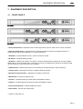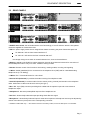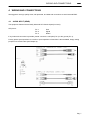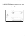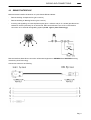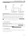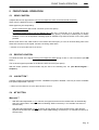
1
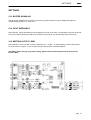
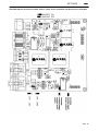
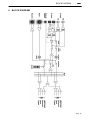
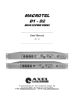
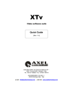
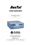
Macrotel
5-7-9
Studio Telephone Hybrid
Operating manual
(Rel. 1.2)
Via Caduti Di Sabbiuno 6/F - 40011 Anzola Emilia - Bologna - Italy - Tel. +39 051 736555 - Fax. +39 051 736170
e-mail: [email protected] - web site: www.axeltechnology.com
CONTENTS
ENG
CONTENTS
1
INSTALLATION WARNINGS.........................................................................................................................4
2
INTRODUCTION..............................................................................................................................................4
3
7
EQUIPMENT DESCRIPTION..........................................................................................................................5
3.1 FRONT PANELS .........................................................................................................................................5
3.2 REAR PANELS............................................................................................................................................6
WIRING AND CONNECTIONS.......................................................................................................................7
4.1 AUDIO INPUT (SEND) ...............................................................................................................................7
4.2 AUDIO OUTPUT (RECEIVE)......................................................................................................................8
4.3 REMOTE INTERFACE................................................................................................................................9
4.4 MEETING INTERFACE............................................................................................................................10
4.5 2 WIRE CONNECTION.............................................................................................................................10
4.6 4 WIRE CONNECTION ** ........................................................................................................................10
4.7 MICROPHONE CONNECTOR (MACROTEL 9 ONLY) .................................................................................11
4.8 HEADPHONES JACK (MACROTEL 9 ONLY)...............................................................................................11
4.9 MIC + HEADPH. SOCKET (MACROTEL 9 ONLY)........................................................................................11
4.10 REC OUT CONNECTOR (MACROTEL 9 ONLY) ..........................................................................................11
FRONT PANEL OPERATION .......................................................................................................................12
5.1 SEND CONTROL ......................................................................................................................................12
5.2 RECEIVE CONTROL ................................................................................................................................12
5.3 4 W BUTTON**.........................................................................................................................................12
5.4 MT BUTTON.............................................................................................................................................12
5.5 HK BUTTON .............................................................................................................................................13
5.6 METER SELECTION.................................................................................................................................13
5.7 MICROPHONE CONTROL (MACROTEL 9 ONLY).......................................................................................13
5.8 MUTE BUTTON (MACROTEL 9 ONLY) .......................................................................................................13
5.9 S BUTTON (MACROTEL 9 ONLY) ................................................................................................................13
5.10 R BUTTON (MACROTEL 9 ONLY)................................................................................................................13
5.11 PHONES POTENTIOMETER (MACROTEL 9 ONLY) ...................................................................................13
5.12 SEND LED BAR (MACROTEL 9 ONLY)........................................................................................................13
SETTINGS .......................................................................................................................................................14
6.1 BUZZER DISABLING...............................................................................................................................14
6.2 INPUT IMPEDANCE.................................................................................................................................14
6.3 MEETING OUTPUT LEVEL .....................................................................................................................14
BLOCK DIAGRAM.........................................................................................................................................16
8
TECHNICAL SPECIFICATIONS ..................................................................................................................17
9
WARRANTY....................................................................................................................................................17
4
5
6
Pag. 3
INSTALLATION WARNINGS
ENG
1 INSTALLATION WARNINGS
- Read carefully the present manual and conserve it
- Macrotel hybrids have been designed and built in conformity with the security laws in force.
- Please use high quality, well shielded wires and balanced links wherever possible.
- The installation has to be carried on by skilled technicians.
- Axel Technology is at Yr. complete disposal for every requirements and troubleshooting. Please read
carefully the manual and the electric layout before contacting our technical department.
- In case of technical problems or faults please do not open the cover and contact the manufacturer
- The illustrations in this manual may differ somewhat from the actual equipment design.
- Please verify that the (protective) earth connection is available.
- ATTENTION: if not otherwise specified, Macrotel is set at 220/230VAC. If different different voltage is
available (ex. 110/115 VAC) you need to open the box and set the voltage switch on the main supply circuit,
located behind the VDE plug.
2 INTRODUCTION
Macrotel is a range of professional, analog telephone hybrids, 2/4 wires, especially designed to satisfy all TV
and radio studio requirements. All the models offer an high level technical performance at a very competitive
price.
Main features are:
- Balanced audio inputs and outputs on XLR connectors with level control on the front panel.
- 2 wire interface with parallel connection to an external telephone set.
- Transformer balanced 4 wire interface (PLUS version).
- Remote control of the following functions: line hooking, meeting enable, incoming call signalling.
- MEETING* function.
- Led meter showing Send, Receive or Meeting levels.
- Automatic line compensation.
- Fully modular structure.
Macrotel
range:
Macrotel 5
Macrotel 7
: 1 telephone line hybrid
: 2 telephone line hybrid
: 1 telephone line hybrid, featuring also: supplementary input/output for microphone and
headphone set + one REC balanced output.
Macrotel
9
* allows system expansion through other Macrotel units
Pag. 4
EQUIPMENT DESCRIPTION
ENG
3 EQUIPMENT DESCRIPTION
3.1
FRONT PANELS
Macrotel5
Macrotel 7
Macrotel 9
- Send potentiometer: it adjusts the level of audio signal sent to phone caller via 2 or 4 wire connection
- Receive potentiometer: it adjusts the phone subscriber audio level which is provided to the user ’s
equipment and which comes through 2 or 4 wire connection in.
- 4W button: it switchs between 2 Wire / 4 Wire connection modes.
- MT button: it enables Meeting function
- HK button: it allows Line hooking. This switch connects / disconnects the hybrid from only the 2 WIRE
telephone line. Hook led blinks when a call (ring) is coming in and lights firmly while line is hooked. Please
note: led switchs on only if phone line is connected.
- R,S,M selector: It selects audio source to be showed by led meter (Receive, Send , Meeting).
- Led Bar meter: it shows Send, Receive or Meeting levels (switched)
- Microphone potentiometer*: it adjusts the microphone input level
- Mute button*: it mutes microphone input
- S button*: it enables listening to Send signal via headphone output
- R button*: it enables listening to Receive signal via headphone output
- Phones potentiometer*: it adjust headphone volume
- Send led bar*: it shows Send signal level
* Available on Macrotel9 only
Pag. 5
EQUIPMENT DESCRIPTION
3.2
ENG
REAR PANELS
Macrotel 5
Macrotel 7
Macrotel 9
- ON/OFF main switch, the led inside switchs on/off accordingly. If it is off while the switch is ON, please
check the supplied AC cord and the fuse.
- VDE: the power supply socket has an integral fuse drawer containing the power fuse and a spare one
-
for 220/230 V AC the fuse is rated at 250 mA T
-
for 110/115 V AC tension the fuse is rated at 500 mA T
the voltage change-over switch is located inside the box, close to the transformer.
- Meeting 1 and 2: 9 pole SubD for system expansion through other Macrotel units and for connection of
several telephone lines to only one ‘Telco’ module of mixing console
- Remote: Remote control of the functions: line hooking, meeting enable, incoming call signalling
- 2 Wires: double (paralleled) RJ11 connectors for the telephone line (LINE) and for a standard analog
telephone set (f.i. for dialling).
- 4 Wires: RX + TX terminal blocks for 4 wire lines**
- Receive XLR (balanced): it provides the audio incoming from telephone caller
- Send XLR (balanced): it receives audio from the source (mixing console) and sends it to the telephone
caller. Audio sent to caller must be a mix-minus (see § 5.1)
- Mic + Ph*: 5 pin (DIN) connector providing both a balanced microphone input and a monochannel
headphone output.
- Headphones*: bichannel preamplified output to fit an headphone set
- Rec Out*: electronically balanced output providing Send+Receive signal
- Microphone*: electronically balanced input for external microphones. Microphone level may be adjusted by
means of the trimmer (Level) next to the corresponding connector.
* Available on Macrotel9 only / ** the related connectors are always visible, even if the 4W option is not installed.
Pag. 6
WIRING AND CONNECTIONS
ENG
4 WIRING AND CONNECTIONS
We suggest to use high quality wires, well protected, and balanced connections to avoid external EMD.
4.1
AUDIO INPUT (SEND)
The equipment features electronically balanced XLR female inputs (line level).
XLR pinout:
Pin 1
Pin 2
Pin 3
Gnd
Signal
Return
If any balanced connection is possible, please connect the cold pole (Pin 3) to the ground (Pin 1).
Factory preset input impedance is 10 kOhm. Input impedance of 600 Ohm is also available, simply setting
jumpers on the main board (see Chapter 0).
Pag. 7
WIRING AND CONNECTIONS
4.2
ENG
AUDIO OUTPUT (RECEIVE)
The equipment features XLR analog outputs electronically balanced by high-quality buffers, capable of
withstanding even low-impedance loads (600Ohm), with levels of up to +20 dBu.
XLR pinout:
Pin 1
Pin 2
Pin 3
Gnd
Signal
Return
In case of unbalanced connections, connect the cold pole (Pin 3) to the ground (Pin 1).
Pag. 8
WIRING AND CONNECTIONS
4.3
ENG
REMOTE INTERFACE
Macrotel remote interface is based on a 5 pole female DIN and allows:
-
Remote hooking of telephone line (pins 4 and 2)
-
Remote enabling of Meeting function (pins 1 and 2)
-
Incoming call signalling. An internal photocoupler (pin 3= collector and pin 5 = emitter) provides a lowresistance closure (150 Ohm) for an arrived call. Max current allowed: 10 mA. Pins 3 and 5 allow
connection of an external call signalling system (like Mr. Light by Axel Technology).
Remote interface allows direct connection of Macrotel equipment to OXYGEN 5 and OXYGEN 7 mixing
consoles by Axel Technology.
Connection scheme is as following:
Pag. 9
WIRING AND CONNECTIONS
4.4
ENG
MEETING INTERFACE
Meeting facilities has been designed especially to allow cascade connection of several Macrotel units
sharing the same Meeting bus.
The cascade (that may include Macrotel 5, 7 or 9) is fed by a N-1output*** of mixing console and provides a
total ‘receive’ signal which is the sum of signals received from telephone lines connected to the single
hybrids.
Meeting cable requires crossed connection among Pin 1and 2 and Pins 4 and 5 (see picture above).
Output meeting impedance may be set to 600 Ohms rather to 10 Kohms. Please refer to Chapter 0.
*** Mix-minus (N-1) is a mix of all audio signals being sent to the telephone line, minus the incoming caller
audio.
Please refer to parr. 5.4 (MT BUTTON) for further Meeting operation modes.
4.5
2 WIRE CONNECTION
Macrotel hybrids operate on standard POTS (Plain Old Telephone Service) / PSTN (Public Switched
Telephone Network) analog telephone lines.
The Macrotel RJ11 socket will accept 4 conductor modular plugs, but only the 2 central conductors (typically
Red & Green ) are used.
The ‘Phone’ socket allows the connection on parallel of a standard telephone set (f.i. for dialling). Please
note that ‘Phone’ socket is always active (i.e. it does not depend on the ‘Hook’ button state).
4.6
4 WIRE CONNECTION **
4 wire connection is provided through two screwed terminal blocks. RX / TX impedance is set at 600 Ohms.
** available as an option (Macrotel PLUS version).
Pag. 10
WIRING AND CONNECTIONS
4.7
ENG
MICROPHONE CONNECTOR (MACROTEL 9 ONLY)
Microphone balanced socket allows connection of external microphones.
Pin 1
Gnd
Pin 2
Signal
Pin 3
Return
Microphone level may be adjusted through the Level trimmer on the rear panel (- 50 ÷
- 90 dB range) and through the ‘Microphone’ control on the front panel.
4.8
HEADPHONES JACK (MACROTEL 9 ONLY)
Headphone plug allows connection to an external headphone set.
The same mono signal is provided on both Ring and Tip pins, by means of two
indipendent amplifier.
Please connect ONLY STEREO headphone set, as ‘Mono’ plugs could damage
internal amplifier stage.
4.9
MIC + HEADPH. SOCKET (MACROTEL 9 ONLY)
5 pole DIN connector provides either a balanced Mic input or a MONO
headphones output.
Please connect to Macrotel 9 ONLY one headphone (HP) set and one
microphone simultaneously.
Connection pinout:
Pin 4
Pin 1
Pin 2
MIC Return
MIC Signal
MIC Gnd
Pin 3
Pin 5
HP Signal
HP Ground
4.10 REC OUT CONNECTOR (MACROTEL 9 ONLY)
REC OUT connector (mono-balanced). It can feed a recording device to record
both the reveived and sent audio.
REC OUT signal (mono) is electronically balanced on XLR male connector with 0
dB gain. Connector pinout:
Pin 1
Gnd
Pin 2
Signal
Pin 3
Return.
Pag. 11
FRONT PANEL OPERATION
ENG
5 FRONT PANEL OPERATION
5.1
SEND CONTROL
It adjusts the level of signal which is sent to the telephone caller via the Send XLR connector.
Send control is applied to both 2 wire and 4 wire ** connections (selectable through 4W button).
Send signal may be composed by:
−
the one coming from ‘Send’ XLR connector (on the rear panel)
−
the Meeting signal coming from the Meeting bus (see parr. 4.4 and parr. 5.4). If jumper J12 on the
mother board (see Chapter 0) is on its A position (factory preset), connection to Meeting bus is always
enabled. If J12 is in its B position, Meeting signal is available only while MT button on the front panel
pressed.
NOTE: Audio sent to the caller must be a mix-minus. Mix-minus (N-1) is a mix of all audio being sent to the
Send XLR connector of the hybrid, minus the incoming caller audio.
** available as an option (Macrotel PLUS version).
5.2
RECEIVE CONTROL
It controls the level of the signal incoming from telephone caller through 2 wire or 4 wire connection (see 4W
button).
The ‘received’ signal is provided on the Receive XLR connector (rear panel).
With MT button pressed, received audio may be sent to the Meeting bus, too (see Block Diagram –
Chapter 6).
5.3
4 W BUTTON**
It allows reception and transmission from/to 2 WIRES lines (button released / LED off) or from/to 4 WIRES
lines (button depressed / LED on).
** 4 Wire ouput is available as an option (Macrotel PLUS version).
5.4
MT BUTTON
Macrotel 7
−
With MT button depressed on one channel, the signal received from the related caller is automatically
sent to the other caller** and is provided on Meeting SubD connectors (f.i. for cascade connection of
several units)
−
With MT button depressed on both channels, phone callers can communicate to each other and the
signal received from both callers is sent to both SubD Meeting connectors (f.i. for cascade connection of
several units).
Pag. 12
FRONT PANEL OPERATION
ENG
Macrotel 5 and 9
−
With MT button depressed, the signal received from caller is only provided on SubD Meeting connectors
(f.i. for cascade connection of several units).
** the second subscriber may listen to the first without MT button pressed only if J12 jumper is on A position (see
block diagram of Chapter 7 and Internal Settings, Chapter 6).
5.5
HK BUTTON
It allows line ‘hooking’ in the 2 WIRE mode. This switch hooks / hangs up for a 2 WIRE telephone line only.
Hook LED blinks when a call is coming in (ring) and lights firmly while line is hooked. Please note: LED
switchs on only if telephone line is connected.
5.6
METER SELECTION
LED meter shows SEND, RECEIVE or MEETING levels depending on related selector position (r, s, m).
5.7
MICROPHONE CONTROL (MACROTEL 9 ONLY)
It adjusts the microphone input level
5.8
MUTE BUTTON (MACROTEL 9 ONLY)
It mutes microphone input. The microphone is muted with the button released.
5.9
S BUTTON (MACROTEL 9 ONLY)
It enables listening to Send signal via headphone output
5.10 R BUTTON (MACROTEL 9 ONLY)
It enables listening to Receive signal via headphone output
5.11 PHONES POTENTIOMETER (MACROTEL 9 ONLY)
It adjusts headphone volume
5.12 SEND LED BAR (MACROTEL 9 ONLY)
It shows Send signal level
Pag. 13
SETTINGS
ENG
SETTINGS
5.13 BUZZER DISABLING
Internal buzzer (signalling an incoming call) is factory preset enabled. It may be disabled through the
corresponding jumper (J 11, close to it).
5.14 INPUT IMPEDANCE
At the delivery, ‘Send’ and Meeting input Impedances are set at 10 Kohm. The impedance may be set to 600
Ohm by moving the jumpers located on the mother board (J10) and on the Meeting board (J4 and J5).
5.15 MEETING OUTPUT LEVEL
At the delivery it is set to 0 dBm. It can be adjusted in the – 6 dBm – 6 dBm range by means of the trimmer
P3 and P4 next to Jumper J 7 and J9 after moving these jumpers to Variable position.
CAUTION: Before moving any jumper setting, please switch off the equipment and disconnect it
from the Main
Pag. 14
SETTINGS
ENG
CAUTION: Before moving any jumper setting, switch off the equipment and disconnect it from Main.
Pag. 15
BLOCK DIAGRAM
ENG
6 BLOCK DIAGRAM
Pag. 16
TECHNICAL SPECIFICATIONS
7
ENG
TECHNICAL SPECIFICATIONS
AUDIO PROGRAM IN / OUT
Connectors
Input impedance
MEETING IN / OUT
Connector
Nominal in / out audio level
DB 9 female
0 dBm
Output level *
XLR, electr. balanced
600 Ohm / 10K Ohm
(selectable)
- inf to + 16 dBm
Input impedance
Output impedance
Noise on Receive output
2 wires separation
4 wires separation
100 Ohm
less than -80 dBm (DIN noise)
less than 25 dB**
less than 70 dB
Output impedance
600 Ohm / 10K Ohm
(selectable)
100 Ohm
2WIRE SECTION
Connector
Nominal input level
Nominal output level
Compensation mode
Impedance
RJ11
- 6 dBm
- 6 dBm
Electronic, transf. decoupled
600 Ohm
4WIRE SECTION
Connector
Impedance
Nominal TX level
Nominal RX level
Terminal block
600 Ohm
0 dBm
0 dBm
GENERAL DATA
Power Supply
Dimension
Weight
220/110V
10VA
434x351x44mm (1 rack unit)
about 4Kg
* nominal line level : - 6 dBm
** it can vary depending on characteristics of telephone line
All measurements are intended at 1 kHz.
8 WARRANTY
The manufacturer offers a 1-year ex works warranty.
Do not open the equipment. The warranty shall be voided if any of the warranty seals are broken.
The manufacturer shall not be liable for damage of any kind deriving from or in relation to incorrect use of the
product.
Pag. 17