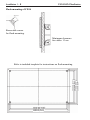
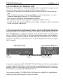
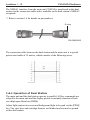
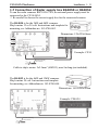
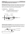
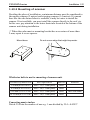
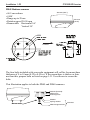
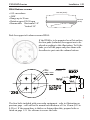
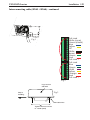
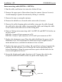
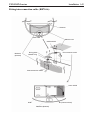
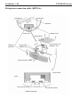
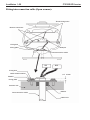
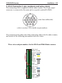
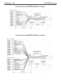
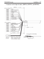
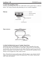
1
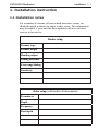
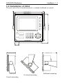
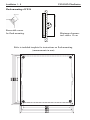
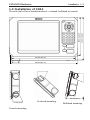
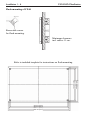
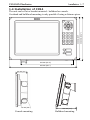
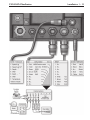
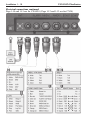
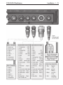
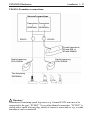
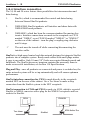
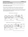
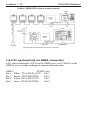
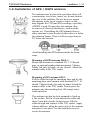
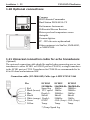
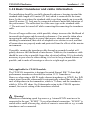
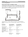
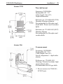
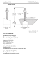
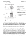
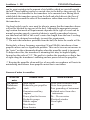
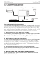
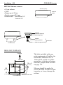
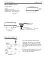
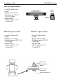
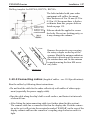
INSTALLATION MANUAL SIMRAD CX34/44/54 NavStation 183-3450-102 06134.20 English About this manual The technical data, information and illustrations contained in this publication were to the best of our knowledge correct at the time of going to print. We reserve the right to change specifications, equipment, installation and maintenance instructions without notice as part of our policy of continuous development and improvement. No part of this publication may be reproduced, stored in a retrieval system or transmitted in any form, electronic or otherwise without prior permission from Simrad AS. No liability can be accepted for any inaccuracies or omissions in the publication, although every care has been taken to make it as complete and accurate as possible. This manual combines installation instructions for the models listed below. All models have the same keypad layout, but will differ according to built-in functions in the selected model: CX34/44/54 CX34/44/54-D CX34/44/54-E CX34/44/54-DE Features Chartplotter • • • • DGPS • • SDGPS • • • • Radar • • • • function Echosounder Optional Optional • • Radar scanner and transducer for echosounder are optional. Safety notices Beware of RF radiation hazard - An active radar scanner radiates powerful RF energy. Continuous exposure to RF energy may cause harmful effects to the human body. It also causes Cardiac Pacemaker to malfunction. A person who uses a Cardiac Pacemaker should under no circumstances be exposed to RF radiation. Note! Most countries accept that RF power density levels below 100 W/m2 cause no significant RF hazard. Distance vs. specified RF power density level: Scanner type Power / size 100 W/m2 DX45 4 kW / 1.5 ft (465 mm) 0.69 m DX60 4 kW / 2.0 ft (615 mm) 0.79 m 10 W/m2 2.18 m 2.50 m Precaution: Do not open the equipment, only authorized Simrad technicians are qualified to do so. If the glass in the screen breaks, be carefull not to cut yourself on the sharp edges of the glass pieces. There is high voltage present inside the scanner which may also be present even after power is turned off. ) The lifetime of the internal battery is minimum 5 years. If not exchanged before it goes flat, all data in the unit’s memory will be lost. We strongly recommend that you frequently store your data on a Simrad DataCard. For exchange of battery, call your local Simrad workshop. Power source, fuse and power cable: Check that the DC power supplied to the unit is within the range of 10 to 32 volts. Note that the appropriate fuse must be employed (see fuse ratings in the Specifications). Ensure that the power cord is firmly attached. Grounding: To reduce electrical interference and risk of electrical shock, properly ground the NavStation to the ship’s ground using the ground screw at the rear of the unit. Good grounding should also be exercised for connected equipment. Cleaning: Do not use any kind of strong solvents e.g. spirit, alcohol, gasoline or oils. Software: The software version of the main unit (see start-up display) should always be informed in a service situation, or when ordering a Dual Station. Installation Table of contents Installation instructions for the CX34/44/54 - series 1. 1.1 1.2 1.3 1.4 1.5 1.6 1.6.1 1.7 1.8 1.8.1 1.8.2 1.8.3 1.8.4 1.8.5 1.9 1.10 1.11 1.12 1.12.1 1.12.2 1.13 1.13.1 1.13.2 1.13.3 1.13.4 1.13.5 1.13.6 1.14 Installation instruction ..................................................................1-1 Installation notes ...........................................................................1-1 Installation of CX34 ......................................................................1-3 Installation of CX44 ..................................................................... 1-5 Installation of CX54 ......................................................................1-7 Location for display unit .............................................................. 1-9 Connection between main unit and Dual Station ........................ 1-9 Operation of Dual Station ...........................................................1-10 Connection of Radar supply box RS4050 or RS4052 .................1-11 Electrical connections .................................................................1-12 Power supply connections ...........................................................1-16 Fuse..............................................................................................1-16 Transducer connection ................................................................1-16 Interface connection ....................................................................1-18 PC up/download via NMEA connection .................................... 1-20 Installation of GPS/DGPS antenna .............................................1-21 Optional connections .................................................................. 1-22 Universal connection cable for echo transducers (option) ......... 1-22 Basic transducer and cable information ......................................1-23 Transducers ................................................................................ 1-24 Determining the position for the transducer ...............................1-27 Installation of scanner .................................................................1-29 Shifting away from obstacles ......................................................1-30 Mounting of scanner....................................................................1-31 Connecting cables .......................................................................1-37 Connector’s pin numbers and wire colors .................................. 1-45 Grounding wire .......................................................................... 1-48 Initial start-up of radar function ................................................. 1-48 Specifications ............................................................................. 1-49 List of Simrad distributors ........................................................ end of manual Table of contents Installation CX34/44/54 NavStation Installation 1 - 1 1. Installation instruction 1.1 Installation notes For a number of reasons, all user-related decisions, setups, etc. should be noted in these two pages as they occur. This information may be helpful if your unit has been updated with new software, reset or in for service. Radar setup Scanner type Scanner height Heading adjust Tuning reference Zero range/timing Sensitivity Echo setup (with built-in Echosounder) Transducer Depth Frequency Keel depth Installation 1 - 2 Other important settings: CX34/44/54 NavStation CX34/44/54 NavStation Installation 1 - 3 1.2 Installation of CX34 The unit can be flat or bracket mounted - overhead, bulkhead or console. 246 mm (9.7”) 220 mm (8.7”) 242 mm (9.5”) 220 mm (8.7”) SIMRAD 212 mm (8.3”) 33 (1.3”) 188 mm (7.4”) 112 mm (4.4”) 78 mm (3.1”) Console mounting. Overhead mounting. Bulkhead mounting. Installation 1 - 4 CX34/44/54 NavStation Flush mounting of CX34 Removable corner for flush mounting. Minimum clearance incl. cables: 15 cm. Refer to included template for instructions on flush mounting. (measurements in mm) CX34/44/54 NavStation Installation 1 - 5 1.3 Installation of CX44 245 mm (9.6”) 220 mm (8.8”) The unit can be flat or bracket mounted - overhead, bulkhead or console. 343 mm (13.5”) 42 (1.7”) 365 mm (14.4”) 75 mm (3.0”) 165 mm (6.5”) 75 mm (3.0”) Console mounting. Overhead mounting. Bulkhead mounting. Installation 1 - 6 CX34/44/54 NavStation Flush mounting of CX44 Removable corner for flush mounting. Minimum clearance incl. cables: 11 cm. 192 mm (7.6”) 202 mm (7.9”) 208 mm (8.2”) 220 mm (8.7”) Refer to included template for instructions on flush mounting. 337 mm (13.3”) 347 mm (13.7”) 353 mm (13.9”) 365 mm (14.4”) CX34/44/54 NavStation Installation 1 - 7 1.4 Installation of CX54 42 (1.7”) 343 mm (13.5”) 460 mm (18.1”) 95 mm (3.7”) 75 mm (3.0”) Console mounting. 195 mm (7.7”) Bulkhead mounting. 339.2 mm (13.4”) 330 mm (13”) The unit can be flat or bracket mounted - bulkhead or console. Overhead and bulkhead mounting is only possible if using a distance piece. Installation 1 - 8 CX34/44/54 NavStation Flush mounting of CX54 Removable corner for flush mounting. Minimum clearance for cables: 13 cm. 297.9 mm (11.7”) 307.9 mm (12.1”) 318 mm (12.5”) 330 mm (13”) Refer to included template for instructions on flush mounting. 427.9 mm (16.8”) 437.9 mm (17.2”) 448 mm (17.6”) 460 mm (18.1”) CX34/44/54 NavStation Installation 1 - 9 1.5 Location for display unit Determine which place is the most suitable and convenient for navigation and general operation after considering the following conditions: - you can see the ship’s bow when you raise or lower your eyes from the display. - there is limited exposure to direct sunlight to avoid overheating - see environment temperature limits in 1.14 Specifications. - there is good ventilation and minimum vibration. - the minimum distance to a magnetic compass is 650mm (25.6”). - provide sufficient space behind the unit to allow for proper cable connections to the rear panel connectors. 1.6 Connection between main unit and Dual Station The DS34/44/54-CX models are remote control units for all the main units in the CX34/44/54 serie. The units with the same model numbers are identical in size e.g. DS44-CX and CX44, so the same installation guides can be applied when performing the installation. When choosing a dual station, the unit does not have to match the main unit in size, as all the mentioned units are compatible. Example: Main unit CX44 Ground Dual Station DS34-CX 15 meters of cable Power Ground Power A special connection cable (153-3002-023) of 15 meters with two male plugs is supplied with the Dual Station. Push one of the male plugs into the receptacle marked NMEA1 on the back of the CX44/54 or REMOTE on the CX34 main unit and the second into the DS34/44/54-CX. An extension cable (153-6080-004) of 10 meters is available for installations requiring a total cable length of up to 25 meters. Installation 1 - 10 CX34/44/54 NavStation The NMEA1 interface from the main unit CX44/54 is transferred to the dual station via the connection cable and is available on the dual station’s NMEA2 receptacle. ) Refer to section 1.8 for details on pin numbers. O-ring 153-3002-023 The connection cable between the dual station and the main unit is a special pair-twisted cable of 15 meters, which consists of the following wires: 1.6.1 Operation of Dual Station The main unit and the dual station operate in parallel. All key commands are relayed to the main unit and the display picture is instantly transferred back via a high speed data bus (HSDb). Adjust light/contrast in screen and background light in keypad via the [PWR] key. The eject keys and cartridge drawers are blinded and can not be opened on the dual station. CX34/44/54 NavStation Installation 1 - 11 1.7 Connection of Radar supply box RS4050 or RS4052 To run the radar scanners RB714/5/6/7/8A, an external power supply must be connected to the CX34/44/54. ) Be carefull to choose the correct supply box for the connected scanner. The RS4050 is for the 2kW and 4kW scanners. Ship’s mains 12 or 24 volt. Instructions and template for mounting, see Addendum no. 183-0700-003. Radar supply 4AF Dimensions: 125x222x81mm Radar motor 6A.3F Main 6A.3F High voltage 160 mAF Example: CX34 Connect to ship’s mains. Cut leads to 50mm long before connection. Cable to ship’s mains: 2x2.5mm2 (AWG13), max.5m long (not included). The RS4052 is for the 6kW and 12kW scanners. Ship’s mains 24 volt. Instructions and template for mounting, see Addendum no. 183-0700-004. Dimensions: 161.9x263x91mm Radar supply 10AT Main 6A.3F Radar motor 3.16AT High voltage 200 mAF Connect to ship’s mains. Cut leads to 50mm long before connection. Example: CX44/54 Installation 1 - 12 CX34/44/54 NavStation 1.8 Electrical connections Page 1-12 and 1-13 are for CX34. (Page 1-14 and 1-15 are for CX44/54) CX34/44/54 NavStation Installation 1 - 13 Installation 1 - 14 CX34/44/54 NavStation Electrical connections continued Page 1-14 and 1-15 are for CX44/54. (Page 1-12 and 1-13 are for CX34) CX34/44/54 NavStation Installation 1 - 15 Installation 1 - 16 CX34/44/54 NavStation 1.8.1 Power supply connections - refer also to section 1.7 The internal voltage regulator will allow the CX34/44/54 to operate normally within the power supply voltage range from 10 to 32 V DC. The CX34/44/54 is connected to external power (battery or radar supply box) by means of the supplied power cable, which is approximately 2 meters long and is not extendable. After connecting the cable to the power source, push the plug as far as it will go into the four pin receptacle marked “PWR” on the rear of the cabinet and turn the plug’s coupling ring clockwise until it makes a click. 1.8.2 Fuse Warning! A fuse should always be installed to protect the unit. Using a fuse which is not specified for your equipment can cause it to blow the instant the CX34/44/54 is switched on or it will not protect the equipment as intended – see fuse rating in section 1.14 Specifications. 1.8.3 Transducer connection Most transducers are supplied with a 10 meter cable for connection to the echosounder unit – CX34/44/54. Push the female plug, as far as it goes, into the receptacle on CX34 marked “ECHO”, or on CX44/54 marked “ECHO1” or/and “ECHO2” on the rear of the cabinet and turn the plug’s coupling ring clockwise until it clicks into locked position ) The unit must be turned off while connecting/disconnecting the transducer cables. CX34: Recommended transducers Airmar single element two-frequency 50/200 kHz transducers i.e. B744V, P319, B45, B256, P66 and P52. CX44/54: Recommended connection and setup (refer to Operator manual) of Simrad supplied transducers Transducer type Simrad C38/200 Simrad C50/200 Low power (100W) combi 38/200 Airmar B250, B260 Airmar P319, P52, P66, B117, B45, SS505, B744V, B256 Unspecified 38/50/200 kHz Port ECHO2 ECHO2 ECHO2 ECHO2 ECHO1 ECHO1 Echosounder setup Simrad Combi 38&200 Simrad Combi 50&200 Special Combi 38&200 Airmar Combi 50&200 Airmar 50 (/200) kHz Airmar 200 (/50) kHz USER 38/50/200 kHz CX34/44/54 NavStation Installation 1 - 17 CX44/54: Transducer connections: Internal connections Transceiver Transceiver 1 2 50/200kHz 38/200kHz ECHO1 ECHO2 Combi transducer 38 and 200, or 50 and 200kHz Single frequency 50 or 200kHz Single frequency 38 or 200kHz Two frequency 50/200kHz ! Warning! Transducers containing speed log sensor e.g. Airmar B744V must never be connected to the port “ECHO2”. To avoid accidental connection, “ECHO2” is sealed with a small silicone plug, which of course is removable so e.g. a combi transducer can be connected. Installation 1 - 18 CX34/44/54 NavStation 1.8.4 Interface connection The 34, 44 and 54 series feature three possibilities for interconnection and data sharing: 1. SimNet, which is recommended for control and data sharing between Simrad SimNet products. 2. NMEA2000, SimNet products will interface and share data with NMEA2000 based products. 3. NMEA0183, which has been the common standard for marine electronics. Interface connections are made to the receptacle on CX34 marked “NMEA”, or on CX44/54 marked “NMEA1” or “NMEA2” on the rear of the cabinet – turn the plug’s coupling ring clockwise until it stops. ) The unit must be turned off while connecting/disconnecting the interface cable. SimNet is a high-speed control and data network designed to integrate SimNet products into a complete system. Ready-made cables with small plugs makes it easy to run cables. Only 10 mm (3/8”) holes are required through panels and bulkheads. The SimNet accessory program contains the necessary items to make a successful installation, see section 1.14 Specifications. Plug and Play - once all products are connected and power is switched on, the entire network system will be set up automatically and will ensure optimum performance. SimNet interface connection for CX34 is made directly to the receptacle marked NET on the rear of the cabinet. Use a Tee Joiner to make a drop connection from the SimNet system to the NET receptacle. SimNet connection to CX44 and CX54 is made via AT44, which is a special SimNet to NMEA converter with a plug for the NMEA2 receptacle and two sockets for SimNet. CX34 CX44/54 NET Tee Joiner NMEA2 SimNet AT44 Active Tee CX34/44/54 NavStation Installation 1 - 19 SimNet power and termination The following simple rules should be observed when installing SimNet: • SimNet must be powered with 12 VDC and connected to the battery via circuit breaker and 5 amp fuse. • Do not connect the SimNet power cable to the same terminals as the Autopilot Computer, Radar, thruster or other high current products. • SimNet should normally be terminated in each end, starting with the power cable with termination in one end and termination plug or wind transducer (with termination) in the other end. SimNet network, small system CX33 Termination not required * Tee Joiner 12V supply * The supply cable has a built-in terminator. SimNet network, small system with Wind transducer CX33 * Tee Joiner 12V supply * The supply cable and wind transducer have a built-in terminator. Installation 1 - 20 CX34/44/54 NavStation SimNet / NMEA2000 network, medium system CX33 * CX44 12V supply Tee Joiner AT44 Active Tee * The supply cable and wind transducer have a built-in terminator. 1.8.5 PC up/download via NMEA connection A PC can be connected to CX34 via the NMEA port, or to CX44/54 via the NMEA2 port, to enable exchange of waypoint and route data. NMEA Pin 6 White Pin 7 Brown Pin 8 Yellow Pin 9 Green SUB-D 9 pin TX A (DATA OUT) Pin 2 TX B (RETURN) Pin 5 RX A (DATA IN) Pin 3 RX B (RETURN) Pin 5 CX34/44/54 NavStation Installation 1 - 21 1.9 Installation of GPS / DGPS antenna The antenna must be placed in a position where tall constructions, steel wires, masts, etc. do not obstruct the view to the satellites. Do not, however, mount the antenna in the top of a mast or tower, as this may degrade the COG and SOG readings, especially if DGPS is used. Do not place the antenna close to sources of electrical inteference, such as radar, satcom, etc. If installing the GPS antenna close to other antennas it must be placed either above or below the radiation beams. There is full coverage down to 20° below the horizon. Avoid installing the GPS antenna inside the beam areas. Mounting of DGPS antenna MGL-3 Mount the antenna on a standard US 1” 14 thread pipe, or optional standard antenna mount. Tighten firmly, but only by hand - no use of tools. Attach the antenna cable to the TNC socket. Mounting of GPS antenna GPS 5 Pull the cable through the mounting base and fix the mounting base onto a mount with standard US 1” 14 thread. Tighten firmly, but only by hand. Attach the antenna cable to the TNC socket. Firmly press the antenna onto the mounting base till it snaps into a locked position. The antenna can also be deck mounted or fixed on a flat surface. Drill a 15 mm hole for the cable and three 5 mm holes for the fixing screws. Pull the cable through and connect to the TNC socket. Apply silicone adhesive along the outer circle of the antenna and press it into place. Use the included screws to secure the antenna. Installation 1 - 22 CX34/44/54 NavStation 1.10 Optional connections SIMRAD -Compass -WR20 RemoteCommander -Dual Station DS34/44/54-CX -Performance Instruments -Differential Beacon Receiver -Water speed and temperature sensor -Autopilot -Yeoman digitizer -PC - WPs & routes up/download -Other equipment via SimNet, NMEA0183, or NMEA2000. 1.11 Universal connection cable for echo transducers (Optional) The universal connection cable should be applied when connecting one or two transducers to either ECHO1 or ECHO2 port on CX44/54, or single transducer to the ECHO port on CX34. Transducers for CX44/54 are recommended to be 60 to 80 ohms and minimum 1kW. Connection cable (153-3004-002) Cable type AMW STYLE 2464 Pin ECHO/1 50/200kHz 1 Red Speed log 2 Black (brown) VCC speed 3 Blue Depth 1+ 4 Shield Shield 5 White (orange) Depth 16 Green GND* 7 Yellow Temp. ECHO2 50&200kHz 50kHz+ 50kHz200kHz+ Shield 200kHz- ECHO2 38&200kHz 200kHz+ 200kHz38kHz+ Shield 38kHz- GND (Temp.) GND (Temp.) Temp. *) Temp./Speed log Temp. CX34/44/54 NavStation Installation 1 - 23 1.12 Basic transducer and cable information The installation should be carefully planned in advance, keeping in mind the standard cable length of 10 meters (32 feet) which is connected to the transducer. In the event where the standard cable is not long enough, up to an additional 10 meters (32 feet) may be connected without a noticeable reduction of the performance. The cable must be of the same type as the standard cable. ) The unit must be turned off while connecting/disconnecting the transducer cable. The use of longer cable runs, while possible, always increases the likelihood of increased interference and decreased performance. Care must be taken when increasing the cable lengths to ensure that proper, adequate and consistent shielding is maintained, that cable of adequate cross section is used, and that all connections are properly made and protected from the effects of the marine environment. If possible, running the transducer cable through a grounded conduit will greatly decrease the likelihood of interference. Likewise, the transducer cable should be run as far as possible from other electrical cabling. If it is absolutely necessary to pass close to other cabling, it is best to keep as much distance as possible, and to make all crossings as close to a right angle as possible. Only applicable for CX44/54 models: The CX44/54’s transmitter is designed to match Simrad 1kW 75 ohms high performance transducers described in section 1.12.1 Transducers. However, when using a 600 W single element transducer e.g. B744V, the 1kW output signal from the echosounder is automatically reduced due to the difference of impedance in the transmitter, which is 75 ohms, and the transducer, which is 185 to 425 ohms. See Echosounder setup in the CX44/54 operator manual, for correct setting of the transducer selected. ! Warning! Transducers containing speed log sensor e.g. Airmar B744V must never be connected to the port “ECHO2”. To avoid accidental connection, “ECHO2” is sealed with a small silicone plug, which of course is removable so e.g. a combi transducer can be connected. Installation 1 - 24 CX34/44/54 NavStation 1.12.1 Transducers Simrad Combi-transducers C50/200 or C38/200 For optimum performance of the CX44/54 echosounder function, the Simrad combi transducers C38/200 and C50/200 are recommended. These transducers also include a water temperature sensor. A variety of alternative mediumrange transducers is available for vessels mainly operating in shallow waters and/or where the size of the transducer is critical. 124.5 92 310 135 400 Combi C50/200 or C38/200 combines two transducers and a temperature sensor in one housing. It has a streamlined shape, designed for mounting onto the hull. Frequency: Beamwidth: Maximum pulse power input: Maximum continuous power input: Storage temperature: Cable length: Maximum transducer depth: 50 and 200 kHz longitudinal 10° / 7° transverse 16° / 7° 38 and 200 kHz longitudinal 13°/ 7° transverse 21° / 7° 1000 W 1000 W 10 W 10 W max.70°C, min. –20°C max.70°C, min. –20°C 10 m (32’) 10 m (32’) 20 meter 20 meter Reference No. 700-3000 Reference No. 700-3001 CX34/44/54 NavStation Airmar P319 Installation 1 - 25 Thru-hull mount Frequency: 50/200 kHz Beamwidth: 45° / 15° Cable length: 10m (32’) Depth information. Reference no. 179-0401-002 (P319) Housing: Reinforced plastic Recommended for fiberglass and metal hulls. Do not use in wooden hulls! Reference no. 179-0401-003 (B117) Housing: Bronze Recommended for fiberglass and wooden hulls. Airmar P66 Transom mount Frequency: 50/200 kHz Beamwidth: 45° / 15° Cable length: 10m (32’) Speed, temperature + depth information Reference no. 179-0401-001 Housing: Chemical resistant, high impact plastic alloy. Recommended for all type hulls. ) Do not connect to CX44/54’s ECHO2 port. Installation 1 - 26 CX34/44/54 NavStation Airmar SS505 Thru-hul stem mount Accomodates hull thickness: Min. no fairing 6 mm (1/4”), Max. with fairing 83 mm (3 1/4”) Frequency: 50/200 kHz Beamwidth: 45° / 15° Cable length: 10m (32’) Depth information. Ref.no. 179-0401-004 (B45) Housing: Bronze Recommended for fiberglass or wooden hulls only. Ref.no. 179-0401-008 (SS505) Housing: Stainless steel Recommended for any hull material. Ref.no. 179-0401-011 Optional fairing CX34/44/54 NavStation Installation 1 - 27 Airmar B744V Thru-hull triducer Frequency: 50/200 kHz Beamwidth: 45° / 15° Cable length: 10m (32’) Speed, temperature + depth information. Ref.no. 179-0401-009 (B744V) Housing: Bronze Recommended for fiberglass and wooden hulls. ) Do not connect to CX44/54’s ECHO2 port. 1.12.2 Determining the position for the transducer The CX34/44/54 is a sophisticated piece of electronic equipment, but how well it will perform under actual operating conditions will be largely dependent upon the location of the transducer and how it has been installed. Careful consideration, therefore, must be given to selecting the mounting location and on deciding the method of installation that best suits the vessel. Air bubbles and turbulence caused by the vessel’s movement through the water will seriously degrade the transducer’s performance. Therefore the transducer should be located well clear of any water intake or discharge line and also clear of any projection along the hull line which might disturb the smooth flow of water. It is of profound importance for good performance of the CX34/44/54 that the water flowing over the transducer be free of bubbles and aeration. If the transducer face is clean but the performance degrades with increasing vessel speed, then aeration of the water flowing under the transducer may be the cause of the poor performance. Due to the varying design of ship’s hulls and different operating speeds, there Installation 1 - 28 CX34/44/54 NavStation can be great variation in the amount of air bubbles which are carried beneath the hull. These bubbles tend to be carried close to the hull as they pass aft. For this reason, it is desirable for the transducer to be mounted on a fairing block which holds the transducer away from the hull and which directs the flow of aerated water around the sides of the transducer rather than over the face of the transducer. On deep keeled vessels, care must be taken to ensure that the transducer beam will not be blocked by any part of the keel. Although the appropriate mounting location that meets all requirements depends on the type of vessel and its normal operating speeds, a practical choice is usually somewhere between one third and one half of the vessel’s water line length from the bow. Leveling blocks may be designed accordingly to meet this requirement. ) The more the transducer protrudes from the hull, the better the results will be. Particularly at lower frequency operation (38 and 50kHz), interference from propeller noise can be a significant problem. This can be seen as an increase in the “noise” on the echosounder display when the propeller speed is increased. To help reduce this, the transducer’s mounting face may be angled slightly forward on the order of 3-5°. The goal is to incline the transducer so that a line of sight along the transducer’s radiating surface passes below the propeller. ) Keeping the propeller clean and free of any nicks or roughness will assist in minimizing interference from propeller noise due to cavitation. Sources of noise to consider: Water/air noise Air bubbles Turbulence Propeller Acoustic noise Main engine Reduction gear propeller shaft Generators auxiliary engines Power plant for freezers Hydraulic pumps Rudder engine Bow thruster Stern thruster Electrical noise Noise from electrical cables Noise from generators Poor grounding of instrument Radiated noise from other instruments Dc – Dc converters Electrical winches Neon lights etc. CX34/44/54-series Installation 1-29 1.13 Installation of scanner This illustration is a typical radar system: Radar scanner Display unit GPS antenna Compass 12/24 Volt supply 12 Volt supply AT44 SimNet How to determine the site of installation A radar’s target detection capacity varies greatly depending on the fitted position of the scanner. An ideal fitting position is a location high above the ship’s keel line where there is no obstacle all around the scanner. In an actual ship, such an ideal location is limited by various factors. Therefore, consider the following suggestions when you determine the place to install the scanner: A. Install scanner away from smoke-stack and mast If the scanner is installed at the same height as the smoke-stack or mast, radar waves may be blocked, crating shadow zones or generating false echoes. Therefore, do not install the scanner at such a position. B. Install scanner forward away from obstacle To avoid creating shadow zones or generating false echoes, install the scanner at a position nearer to the ship’s bow away from obstacles. When installing the scanner on a mast, position it in front of the mast. If obstacles cannot be avoided for the ship’s structural reasons, refer to “Shifting away from obstacles” described in section 1.13.1. C. Do not install the scanner near hot or heat-generating items Do not install the scanner at a position where it may be subjected to smoke or hot air from smoke-stacks or heat from lamps. D. Install the scanner away from antennas or other equipment Install the scanner as far away as possible from the antennas of a direction finder, radio transceiver, etc.. Installation 1-30 CX34/44/54-series 1.13.1 Shifting away from obstacles Shifting from keel line: By shifting the scanner position from the keel line to the starboard side of the ship, it is possible to move shadow zones to the port side which makes it possible to keep a clear vision in the bow direction. The distance to be shifted can be obtained by calculation depending on the distance from the scanner to obstacles using the following equation: Ls=0.4R+D/2 [m] (when R<15 m) Ls=0.025R+D/2 [m] (when R>15 m) where Ls= distance to be shifted from keel line D= diameter of obstacle on keel line R= distance from scanner to obstacle Scanner unit Obstacle D Ls Keel line R Obtaining sufficient dip angle: Raise the scanner position so that there is a sufficient dip angle available between the line of sight from the scanner to the obstacle and the horizontal line. By raising the dip angle above 5° it is possible to prevent mid and long distance shadow zones. The radar cannot detect objects below the line of sight. θ Horizontal line Line of sight CX34/44/54-series Installation 1-31 1.13.2 Mounting of scanner Deciding the place of installation, a minimum distance must be considered to the master compass (2 meters) and steering compass (1.4 meters). If a mount base like the one shown below is available, it may be easier to install the scanner. If not available, you may install the scanner directly to the roof, etc. In this case, pay attention to the water drain tube located at the bottom of the scanner unit during installation. ) When the radar mast or mounting bracket has a curvature of more than 2 mm, repair it or use spacers. Mount base Do not use an edge that might trap water Which size bolts to use for mounting of scanner unit: Thickness of mount base 1-4 mm (0.04-0.16 in.) 4-9 mm (0.16-0.35 in.) 9-14 mm (0.35-0.55 in.) 14-19 mm (0.55-0.75 in.) Bolt requirement M10 × 15 (1.5 mm pitch) M10 × 20 (1.5 mm pitch) M10 × 25 (1.5 mm pitch) M10 × 30 (1.5 mm pitch) Material Steel Steel Steel Steel Remarks Incl. with radar Converting mm to inches: Divide 25.4 into the number of mm e.g. 1 mm divided by 25.4 = 0.03937 Installation 1-32 CX34/44/54-series DX45 Radome scanner 465 mm (18.3”) • 46.5 cm radome • 4 kW • Range up to 28 nm • Rotation speed 20-50 rpm • Beamwidth: Horizontal 5.6° Vertical 30° 261 mm (10.3”) Forward The four bolts included with your radar equipment will suffice for mount base thickness of 9 to 14 mm (0.35 to 0.55 in.). If the mount base is thicker or thinner than this, prepare bolts as listed on page 1-31. Use silicone to secure the bolts. This illustration applies to both the DX45 and DX60 scanners: Radome (bottom) Rubber foot Mounting base Washer Spring washer Fix four bolts M10 Hexagonal bolt Included CX34/44/54-series Installation 1-33 DX60 Radome scanner • 61.5 cm radome • 4 kW • Range up to 36 nm • Rotation speed 20-50 rpm • Beamwidth: Horizontal 3.8° Vertical 30° 615 mm (24.2”) 261 mm (10.3”) Pads for support of radome scanner DX60: If the DX60 is to be mounted on a flat surface, the four pads (included) for support are to be placed according to this illustration. To fit the pads, peel off the paper and place them with the adhesive part onto the radome bottom. Forward The four bolts included with your radar equipment - refer to illustration on previous page - will suffice for mount base thickness of 9 to 14 mm (0.35 to 0.55 in.). If the mount base is thicker or thinner than this, prepare bolts as listed on page 1-31. Use silicone to secure the bolts. Installation 1-34 CX34/44/54-series RB714A Radome scanner 448 mm (17.9”) • 45 cm radome • 2 kW • Range up to 24 nm • Rotation speed 24 rpm • Beamwidth: Horizontal 5.9° Vertical 25° 220 mm (8.8”) Chassis Radome (bottom) Mounting base Washer Spring washer Included M10 Hexagonal bolt Fix four bolts DRILLING TEMPLATE Forward 140mm (5.51 in.) 12φ × 5 (0.47 in.) 60 (2.36 in.) 140 Center (5.51 in.) 30 (1.18 in.) Measurements= mm For air tube The bolts included with your radar equipment will suffice for mount base thickness of 9 to 14 mm (0.35 to 0.55 in.). If the mount base is thicker or thinner than this, prepare bolts as listed on page 1-31. Silicone should be applied to secure the bolts. Do not use locking putty, as it may damage the radome. CX34/44/54-series Installation 1-35 RB715A Radome scanner • 65 cm radome • 4 kW • Range up to 36 nm • Rotation speed 24 or 48 rpm • Beamwidth: Horizontal 3.9° Vertical 25° 660 mm (26.4”) 255 mm (10.2”) Chassis Radome (bottom) Mounting base Washer Spring washer Fix four bolts Included M10 Hexagonal bolt DRILLING TEMPLATE The bolts included with your radar equipment will suffice for mount base thickness of 9 to 14 mm (0.35 to 0.55 in.). If the mount base is thicker or thinner than this, prepare bolts as listed on page 1-31. Silicone should be applied to secure the bolts. Do not use locking putty, as it may damage the radome. Installation 1-36 CX34/44/54-series RB716A Open scanner • 3 or 4ft Open array • 4 kW • Range up to 48 nm • Rotation speed 24 or 48 (24V) rpm • Beamwidth: Horizontal 2.5°, 1.8° Vertical 22° 4’ 1346mm (53.8”) 3’ 1034mm (41.4”) 330mm (13.2”) 450mm (18”) RB717A Open scanner RB718A Open scanner • 4 or 6 ft Open array • 6 kW • Range up to 72 nm • Rotation speed (24V) 24 or 48 rpm • Beamwidth: Horizontal 1.8°, 1.2° Vertical 22° • 4 or 6 ft Open array • 12 kW • Range up to 96 nm • Rotation speed (24V) 24 or 48 rpm • Beamwidth: Horizontal 1.8°, 1.2° Vertical 22° Double nuts Spring washer Washer Scanner base Mount base M12 Hexagonal bolt CX34/44/54-series Installation 1-37 Drilling template for RB716A, RB717A, RB718A. Rotation Radius R550 (3 ft. ant.) R700 (4 ft. ant.) R985 (6 ft. ant.) Front The bolts included with your radar equipment will suffice for mount base thickness of 9 to 14 mm (0.35 to 0.55 in.). If the mount base is thicker or thinner than this, prepare bolts as listed on page 1-31. Silicone should be applied to secure the bolts. Do not use locking putty, as it may damage the radome. Remove the protective cap covering the rotary coupler on the top of the scanner. Match the antenna radiation direction to direction of the arrow on the rotation base and fix the antenna in position using the four M8 accessory bolts. IMPORTANT 1.13.3 Connecting cables (length of cables – see 1.14 Specifications) Run the cables by following these instructions: • Do not bind the cable for the radar collectively with cables of other equipment (especially the power supply cable). • Run the cable along the ship’s hull or wall surface, and fasten it at intervals of about 40 cm. • After fitting the interconnecting cable (see further ahead in this section): The scanner cable has a connector fitted on the display side. Push the connector as far as it will go into the receptacle marked ‘RADAR’ on the rear of the display cabinet and turn the connector’s coupling ring clockwise until it is tight. Installation 1-38 CX34/44/54-series Interconnecting cable (DX45 + DX60) 1. Run the cable and fasten it at intervals of about 40 cm. 2. Remove the upper part of the radome from the scanner (loosen 4 screws with incl. Allen key). Avoid bumping it against the antenna by lifting it vertically. 3. Remove the shield cover located on the astern side (8 screws) - use a T20 screwdriver. 4. Pass the cable up through the opening and place the cable screen into the groove (Fig.1), and then position the rubber ring at the cable inlet and tighten the coupling ring. 5. Attach the thick wires to the included 8-pin connector and the thin wires to the included 11-pin connector (Fig.2). Fix connectors to PCB (Fig.1). 6. Replace the shield cover. Be careful that no cables are caught between main unit and cover, and that the antenna is free to rotate. 7. Replace the upper part of the radome (Fig.3): Be careful not to bump it against the antenna. The small alignment mark on the upper part should be positioned just above the cable inlet where there is a similar mark on the lower part. The holes for the 4 screws should now be aligned. Tighten the screws to 1.5 Nm (max). 8. Ensure the display unit’s radar function is off. Connect the cable to the receptacle marked RADAR on the rear panel of the display unit. CX34/44/54-series Installation 1-39 Interconnecting cable (DX45 + DX60) - continued Pull cord White (coax) Green (shield) Blue Yellow NC White Brown Green Red Pull cord 1 Fig.1 Pull cord Blue Green Violet Yellow Orange Red Pull cord 1 Fig.2 Logo seal on side wall Fig.3 Ship’s heading Cable inlet Tighten the four screws to 1.5 Nm (max) Installation 1-40 CX34/44/54-series Interconnecting cable (RB714A + RB715A) 1. Run the cable, and fasten it at intervals of about 40 cm. 2. Remove the upper part of the radome from the scanner (loosen 4 screws). Avoid bumping it against the antenna by lifting it vertically. 3. Remove the tape securing the antenna. 4. Remove the shield cover located on the astern side (4 screws). 5. Remove the cable clamping plate and rubber ring, pass the cable through the cable inlet, place the rubber ring around the cable, and clamp the cable to the scanner unit with screws via the fixing plate. 6. Refer to ‘Fitting interconnecting cable’ for RB714A and RB715A further on in this section. RB714A: Connect 10-pin connector to X1. RB715A: Connect 7-pin connector to X11 and 9-pin connector to X12. 7. Replace the aluminum cover: Place the cable shield into the groove in the aluminum cover. Be careful that the cable does not get caught between main unit and cover, and that the antenna is free to rotate. 8. Replace the upper part of the radome: Be careful not to bump it against the antenna. Be sure that the cover is fitted in the correct direction (refer to below illustration). Align the upper and lower parts with the holes for the screws and tighten the screws. 9. Ensure the display unit’s radar function is off. Connect the cable to the receptacle marked RADAR on the rear panel of the display unit. Logo seal on side wall Ship’s heading Cable inlet Fix four screws CX34/44/54-series Installation 1-41 Fitting interconnection cable (RB714A): Antenna Stern side Shield cover Cable shield Radome (bottom) Fixing plate Fix connector on X1 Rubber ring Interconnection cable Inner shield PCB X1 (Connect here) Radome (bottom) Installation 1-42 CX34/44/54-series Fitting interconnection cable (RB715A): Antenna Stern side Shield cover Cable shield Fixing plate Radome (bottom) Rubber ring Fix connector on PCB X11, X12 Interconnection cable Inner shield PCB X11 (Connect here) Radome (bottom) X12 (Connect here) CX34/44/54-series Installation 1-43 Interconnecting cable (Open Scanner) 1. Run the cable, and fasten it at intervals of about 40 cm. 2. Use a T-wrench to remove the back covers of the scanner unit. 3. Remove the two bolts securing the transceiver and pull out the transceiver after removing two connectors: to Motor (X1) and to Heading switch (X2). 4. Remove the four bolts securing the fixing plate at the cable entrance. 5. Remove the metal fixing plate, rubber seal and washer that secures the cable. 6. Pass the cable through as shown in the diagram on next page. 7. Replace the above items and tighten the bolts. 8. Return the transceiver to its original position and secure it with the removed bolts. 9. Connect 7-pin connector to X11 and 9-pin connector to X12 of PCB. 10. Re-connect the two connectors removed at point 4. 11. Refit the scanner covers. 12. Take care the cable is not pinched when refitting the cover. 13. Ensure that the radar is off. 14. Connect the cable to the receptacle marked RADAR on the rear panel of the display unit. ) See ‘Fitting interconnection cable’ on next page. Installation 1-44 CX34/44/54-series Fitting interconnection cable (Open scanner): TR unit fixing bolts Remove connector Fixing bolt Clumper Fixing plate Interconnection cable X11 X12 Fixing bolt Cable shield terminal 5 10 mm Washer Fixing plate Scanner unit Interconnection cable Rubber Cable inlet CX34/44/54-series Installation 1-45 1.13.4 Connector’s pin numbers and wire colors The connecting cable is supplied with the radar scanner. The 18-pin round connector is connected to the main unit’s receptacle marked RADAR: 2 1 4 3 7 8 12 16 5 6 9 10 14 13 17 11 (seen from solder side) 15 18 – refer to section 1.8 for details on pin numbers. The connector at the other end of the connecting cable is for the radar scanner, and consist of the following pin numbers and wire colors: Wire colors and pin numbers for the DX45 and DX60 Radar scanner Pull cord White (coax) Green (shield) Blue Yellow NC White Brown Green Red Pull cord 1 Pull cord Blue Green Violet Yellow Orange Red Pull cord 1 Installation 1-46 CX34/44/54-series Connector for the RB714A Radar scanner Connector for the RB715A Radar scanner CX34/44/54-series Installation 1-47 Connector for the Open Scanners (RB716A, RB717A, and RB718A) Installation 1-48 CX34/44/54-series 1.13.5 Grounding wire Connect a grounding wire from one of the bolts on the scanner base, as shown below. The crimp terminal and grounding wire are installer-supplied. Chassis Radome Radome (bottom) Mount base To ship’s hull Crimp terminal Grounding wire Open scanner Terminal (accessory) Ground wire 1.13.6 Initial start-up of radar function Initial start-up after installation or after long storage (6 months), the scanner will need an extra 20 minutes to warm up, so after Power on and going into Standby, the radar function must be left in Standby mode for an extra 20 minutes to properly warm up the scanner. This way you will contribute to the lifetime of the magnetron in the radar scanner. Note: Normal start-up at regular usage will take approx. two minutes for the scanner to warm up and be ready for transmission. For further instructions, refer to the user manual. CX34/44/54-series Installation 1-49 1.14 Specifications of the CX34, 44 & 54 General data Power supply: 12 and 24 V DC (10-32 V DC max) 20-70 watt (+ Radar supply box - see next page) Power cable: 2 m, 4 pin female connector, (153-5000-007), inclusive: - power fuse T6.3A slow (5x20mm) - fuse for DX radar scanners F8.0A fast (5x20mm) CSD: Compass Safe Distance: 650mm (25.6”) Dimensions: CX34: H:220 mm (8.7”) L:220 mm (8.7”) D:112 mm (4.5”) CX44: H:220 mm (8.7”) L:365 mm (14.6”) D:75 mm (3”) CX54: H:330 mm (13”) L:460 mm (18.1”) D:95 mm (3.7”) Weight: CX34: 3.2 kg (7 lb), CX44: 3.7 kg (8.1 lb), CX54: 6.6 kg (14.5 lb) Environment: 0 to +50°C (32 to 122°F), waterproof USC 46 CFR and IP55 Housing: Casted aluminum back, polycarbonate front Display: CX34 7”, CX44 10”, CX54 15”: TFT color, power backlight, 640x480 pixel, bonded with anti-reflective coating. CX44SV 10”: ATFT color, power backlight, 640x480 pixel, front glass with Anti-Reflective coating. Interfaces: CX34: 1 port in/out NMEA0183, 1 port SimNet/NMEA2000 CX44/54: 2 ports in/out NMEA0183 (incl.SimNet/NMEA2000 via AT44 Active Tee), PC up/download WPL and RTE - alarm: CX34: Signal output 5 Volt 50 mA CX44/54: Alarm relay 24V 0.5 A (contact closure) - log out: CX44/54: 200 pulses/nm (5 Volt pulses) Main fuse: T6.3A slow (5x20 mm) SimNet control Maximum number of products connected in a network:.....................50 units Maximum cable length (excl. 30 m wind transducer cable): .......120 m (400’) Bit rate of the bus: ................................................................... 250 kbit/second Maximum DC current through a single SimNet plug: ................................5A SimNet power supply: ................................................................. 10.8-15 VDC Maximum drop cable length:.............................................................6 m (20’) Maximum total length of all drop cables ......................................60 m (200’) Environmental protection: Cable and plug/connector system: .................IP66 Temperature: ...................................................................... max. 70°C (158°F) Installation 1-50 CX34/44/54-series Radar supply box RS4050 to run radar scanners RB714/5/6A Addendum: 183-0700-003 Dimensions: H:125 mm, L:222 mm, D:81 mm Power supply: 12 and 24 V DC (10-32 V DC max) Fuses: Radar supply fuse 4A F Main fuse 6A.3F High voltage fuse 160 mAF Radar motor fuse 6A.3F Radar supply box RS4052 to run radar scanners RB717/8A Addendum: 183-0700-004 Dimensions: H:161.9 mm, L:263 mm, D:91 mm Power supply: 24 V DC (18-32 V DC max) Fuses: Radar supply fuse 10 AT Main fuse 6A.3F High voltage fuse 200 mAF Radar motor fuse 3.16AT GPS section Receiver type: 14 channel parallel, C/A code, 8 state Kalman filter Accuracy: Position (DGPS): 2-5 m RMS Position (SDGPS): 3-7 m RMS Position (GPS): 8 m RMS Speed: 0.1 kn Course: 1° Speed filter: 10 settings Update rate: 1 second interval, typical Dynamics: Velocity: 600 km/h Acceleration: 10 m / s2 Weight: GPS antenna GPS 5 Patch H:100 mm (top=30, bottom=70) Diameter:86 mm 122 g (top=83, bottom=39) Environment: Mounting: Cable: -35°C to +75°C, 95% rel. 1” 14 thread (standard US) 10 m RG58 (standard), 15 m RG223 (option), max. 30 m RG213 Type: Dimensions: DGPS antenna MGL-3 Patch and H-field H:75 mm Diameter:127 mm 600 g CX34/44/54-series Installation 1-51 Chartplotter section Chart system: C-MAP MAX or NT+ Presentation: Dual chart - two charts in individual scales and detail levels Internal memory: Dynamic storage with combinations of/or totals up to: 35,000 marks/waypoints 10,000 waypoints with name (25 characters) 50,000 trackpoints 50,000 line sections 1,000 routes Radar section Display modes: Head Up, North Up, True Motion, Dual Range. Range scale: 0.125–48 nm in 11 steps or multi range. Min. range: 30 meter Range resolution: 30 meter Bearing accuracy: 1° or better Off-center: Max 66%. Guard zone: Can be set at any desired distance and angle in any desired width. IN and OUT modes are available. Stretch: AUTO, PULSE, VIDEO. Trail (wake): 30 sec., 1, 2, 5, 10, 15, 30 min. or permanent. Radar radome multiVision scanners DX45 and DX60 Approvals: FCC part 80, FCCID TPADX6000105. EU Declaration of Conformity, 1999/5/EC, EN60945. Dimensions: DX45: Ø 465 mm (18.3”), H 261 mm (10.3“) DX60: Ø 615 mm (24.2”), H 261 mm (10.3“) Weight: DX45 = 10 kg (22 lb), DX60 = 11.5 kg (25.4 lb) Range scale: DX45 = max. 28 nm, DX60 = max. 36 nm. Input voltage: 12* and 24 V DC (10-32 V DC max) from display unit. *) 24 V DC (14-32 V DC max) for scanner cables longer than 20 m. Consumption: 60 W (12V 5A) or less (Display and scanner) Standby: 30 W (12V 2.5A) or less. Environment: Waterproof to IP66. Temperature range: -25°C to +55°C (13°F to 131°F). Other data according to IEC62252. Transmitter: 4 kW solid-state modular driving magnetron, 9410 +/- 30 MHz frequency, 0.07-0.7 μs pulse length. Receiver: Semi-log, 5.5 dB, 64 MHz (nominal) IF frequency, 14/4 MHz bandwidth. Installation 1-52 CX34/44/54-series Antenna: Slotted waveguide array, horizontal polarization, rotation rate 20-50 rpm. - beam width: DX45 = 5.6° horizontal, 30° vertical. DX60 = 3.8° horizontal, 30° vertical. Housing: Casted aluminum and ASA. Cables: 10m 153.3003.100 15m 153.3003.150 20m 153.3003.200 30m 153.3003.300 40m 153.3003.400 Radar radome scanners Radome: Scanner: Range: Rotation speed: Beamwidth: Horizontal Vertical Cables: 10m 15m 20m 30m 40m Radar open scanners Open array: Scanner: Range: Rotation speed: RB714A 450 mm 2 kW to 24 nm 24 rpm 5.9° 25° 153.3002.012 153.3002.013 153.3002.014 153.3002.314 153.3002.414 RB716A 3 or 4 ft 4 kW to 48 nm 24 or 48 (24V) rpm Beamwidth: Horizontal 2.5°, 1.8° Vertical 22° Cables: 10m 153.3002.008 15m 153.3002.009 20m 153.3002.010 30m 153.3002.030 40m 153.3002.040 RB715A 650 mm 4 kW to 36 nm 24 or 4 8rpm 3.9° 25° 153.3002.015 153.3002.016 153.3002.017 153.3002.317 153.3002.417 RB717A 4 or 6 ft 6 kW to 72 nm 24 or 48 (24V) rpm 1.8°, 1.2° 22° 153.3002.008 153.3002.009 153.3002.010 153.3002.030 153.3002.040 RB718A 4 or 6 ft 12 kW to 96 nm 24 or 48 (24V) rpm 1.8°, 1.2° 22° 153.3002.008 153.3002.009 153.3002.010 153.3002.310 153.3002.410 CX34/44/54-series Installation 1-53 Echosounder section (CX34) Frequencies: 50 or 200 kHz, selectable Transmit power: Variable up to 600 watt RMS (4,800 W PP) Impedance: 175 / 425 ohm Display ranges: 5 to 1000 m (50kHz) or 5 to 400 m (200kHz), manual and auto mode. Detection ranges: Frequency Beam Bottom 50 kHz 45° 800 m / 2,400 ft 200 kHz 15° 350 m / 1,050 ft Pulse length: Transmission rate: Alarms: Zoom mode: Event marker: Picture speed: Noise filter: Echo presentation: Temperature: Speed: Short, medium, long and auto 10 pings per second Fish, max. and min. depth Bottom and VRM expansion, 6 to 50 meter, feet or fathom At current ping and depth memory True distance or time, high, medium, low, and freeze User selectable on/off A-scope and white line discrimination Sensor or NMEA Sensor or NMEA Echosounder section (CX44/54) Frequencies: 38, 50 and 200 kHz, selectable Output power: Variable up to 1 kW RMS per channel Impedance: 75 ohm Display ranges: 5 to 2000 m (38/50 kHz) or 5 to 400 m (200 kHz), manual and auto mode. Max detection ranges: Frequency Beam Fish* Bottom* 38 kHz 13x21° 410 m 1800 m 50 kHz 10x16° 430 m 1500 m 200 kHz 7° 280 m 400 m *Single Fish Target Strength: -30dB (60 cm cod) *Bottom Back Scattering Strength: -20 dB *Simrad transducer 38/200 or 50/200 Pulse length: Transmission rate: Short, medium, long and auto 10 pings per second Installation 1-54 CX34/44/54-series Alarms: Zoom mode: Fish, max. and min. depth Shift, bottom and VRM expansion, 3 to 50 meter, feet or fathom Event marker: At current ping and depth memory Picture speed: True distance or time, high, medium, low, and freeze Noise filter: User selectable on/off Echo presentation: A-scope and white line discrimination Temperature: Sensor or NMEA Speed: Sensor or NMEA 50/200kHz medium-range transducers (Airmar Des.A) B256: 1 kW medium range transducer, 16x28° and 4x6° beams. B45: 600 W bronze stem mount transducer, 45° and 15° beam. B744V: 600 W bronze thru hull triducer, depth, speed and temperature, 45° and 15° beam. P66: 600 W plastic transom mount triducer, depth, speed and temperature, 45° and 15° beam. P319: 600 W plastic thru-hull transducer, 45° and 15° beam. ST850: Speed and temperature only. Dual frequency transducers (CX44/54) Simrad 38&200, 1 kW high performance combi transducer 38 and 200 kHz, 13x21° and 7° beams. Simrad 50&200, 1 kW high performance combi transducer 50 and 200 kHz, 10x16° and 7° beams. Airmar B260-22, 1 kW combi transducer 50 and 200 kHz, 19° and 6° beams. Cables included Power cable, 2 m, 4 pin female connector, (153-5000-007), inclusive: - power fuse T6.3A slow (5x20mm) - fuse for DX radar scanners F8.0A fast (5x20mm) NMEA cable, 1.5 m, 9-pin female connector (153-3002-005) Antenna cable, 10 m RG58 (153-2025-004) Accessories included for CX44/54 AT44 Active Tee with connector for SimNet control (153-5555-449) CX34/44/54-series Installation 1-55 SimNet cables and accessories (not included) SimNet cable 0.3 m (1’), (24005829) SimNet cable 2 m (6.6’), (24005837) SimNet cable 5 m (16.6’), (24005845) SimNet cable 10 m (33’), (24005852) SimNet Tee Joiner, 3 sockets (24005860) SimNet Multi Joiner, 7 sockets (24006298) SimNet cable gland (24005878) SimNet protection plug (24005886) SimNet termination plug (24005894) 2 m (6.6’) SimNet power incl. termination (24005902) 2 m (6.6’) SimNet power excl. termination (24005910) AT10 Universal NMEA0183 converter (24005936) SimNet cable protection cap (24005928) SimNet/NMEA2000 drop cable (24005729) Options for CX34/44/54 Simrad DataCards C-MAP electronic charts NT+ and MAX WR20 RemoteCommander 6-channel NMEA Buffer RS5345 PC data cable, 1.5 m (153-3002-024) Antenna cable 15 m RG223 Universal connection cable for echo transducer, 2 m (153-3004-002) DS34-CX Dual Station*, 7” TFT LCD color screen DS44-CX Dual Station*, 10” TFT/ATFT LCD color screen DS54-CX Dual Station*, 15” TFT LCD color screen *) incl. 15 m cable (153-3002-023) Extension cable for dual station, 10 m (153-6080-004) Options only for CX34 Alarm/NMEA cable, 2 m (153-6080-001) Options only for CX44 TiltFrame, 10” (700-5000-042) Options only for CX44/54 NMEA1 cable, 1.5 m, 9-pin male connector (153-3002-004) TL50 TurboLoader, external disc drive and NMEA interface Sunhood, 10” (140-6515) or 15” (140-6752) Installation 1-56 CX34/44/54-series