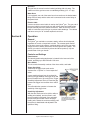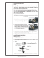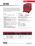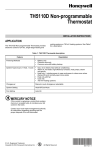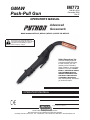
1
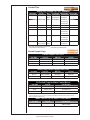
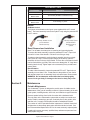
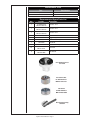
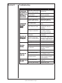
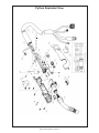
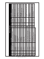
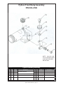
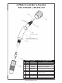
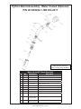
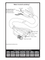
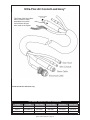
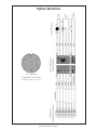
IM773
GMAW
Push-Pull Gun
MK 091-0524
December 2006
Rev. E
OPERATOR'S MANUAL
Advanced
Gooseneck
Model numbers K2211-2, K2211-3, K2212-1, K2212-2 & K2212-3
This manual covers equipment which is no
longer in production by The Lincoln Electric Co.
Specifications and availability of optional
features may have changed.
Safety Depends on You
Lincoln arc welding equipment
is designed and built with safety
in mind. However, your overall safety can be increased by
proper installation...and thoughtful
operation on your part. DO NOT
INSTALL, OPERATE OR REPAIR
THIS EQUIPMENT WITHOUT
READING THIS MANUAL AND
THE SAFETY PRECAUTIONS
CONTAINED THROUGHOUT.
And, most importantly, think before
you act and be careful.
OPERATOR’S MANUAL
Copyright © 2006 Lincoln Global Inc.
World's Leader in Welding and Cutting Products
Sales and Service through Subsidiaries and Distibutors Worldwide
Cleveland, Ohio 44117-1199 U.S.A. TEL: 216.481.8100 FAX: 216.486.1751 WEB SITE: www.lincolnelectric.com
Table of Contents
Safety Considerations ........................................................................i-iii
Installation ............................................................................... Section A
Technical Specifications .....................................................................................1
Support Equipment Required.............................................................................1
Coolant Recommendations................................................................................1
Gun Lead Connections ......................................................................................2
Operation.................................................................................Section B
General ..............................................................................................................2
Controls and Settings.........................................................................................2
Trigger Adjustment .............................................................................................3
Drive Roll and Idler Rolls....................................................................................3
Accessories .............................................................................Section C
Optional Kits.......................................................................................................4
Conduits .............................................................................................................5
Snake Skins .......................................................................................................5
Contact Tips .......................................................................................................5
Gas Cups ...........................................................................................................5
Barrels................................................................................................................6
Maintenance ............................................................................Section D
Periodic Maintenance.........................................................................................7
Recommended Spare Parts List ........................................................................8
Troubleshooting.......................................................................Section E
Troubleshooting Guide.....................................................................................10
Testing The Gun...............................................................................................10
Appendices..............................................................................Section F
Diagrams / Parts List........................................................................................ 11
Mechanical .......................................................................................................12
Electrical...........................................................................................................20
Safety Warnings
Warranty
Declaration of Conformity for
European Community (CE) Products
Note
This information is provided for units with CE certification (see rating label on unit).
MK Products, Inc.
Manufacturer’s Name:
16882 Armstrong Ave.
Irvine, CA 92606
Declares that the product:
Python®
conforms to the following Directives and Standards:
Directives
Low Voltage Directive: 73/23/EEC
Electromagnetic Compatibility (EMC) Directive: 89/336/EEC
Standards
Arc Welding Equipment Part I: Welding Power Sources: IEC 60974-1
(September 1998 - Second Edition)
Arc Welding Equipment: Wirefeed Systems: IEC 974-5
(September 1997 - Draft Revision)
Degrees of Protection Provided by Enclosures (IP Code): IEC 529:1989
(November 1989 - First Edition)
Insulation Coordination For Equipment With Low-Voltage Systems:
Part I: Principles, Requirements and Tests: IEC 664-1: 1992
(October 1992 - First Edition)
Electromagnetic Compatibility, (EMC): EN 50199
(August 1995)
Torches And Guns For Arc Welding, EN 50078
Python Owner's Manual Page i
2
( ) * + ,- . ,- / % ( 0 ! "
# $
%
" ! &
'
" $ $
% $
%( # %
% ( $
" "
%#
% !
%# % ) $ $" %
* $
% +"
,
- . /% '0* 0
- . 1
'* 0
- 0 $ /% ( % %
% % 11 ,-
( ) ( 2 *+ ( 0
% % % 3
( ( ,- (
/ % (4 5 "
!"# $ % & '
231 4. 5
%
6 /
1 / % & ' 1 0
$
% $ $ + "
)
% '
1.* " %
$ " %! 6 # " 6" $ " $ / '/*
% 6 )
" # # " ! + "
+ $
$
% %)
& 6 ) 7
7
% 7
/
' 8 $9: ;2 ):< 6 . % ) % '
% 6 4 %
% 6 3 = 7
% *0.+ = 0. 6 >
2 ?5
Python Owner's Manual Page ii
2
0.45 345
7 6"
5 3 1 % 3 4 '
5 / 4 %
1
3 , /
;
- *
!E>+ 7
5 / % 1
5 . % % '
) '
,- F % ,3
$
$
/
;
;
$
) 1
-% / F> /
* +
5 < % ) '
4. ! 6"
%
# % % # ' # ;
@
A 4 A % % # % ,- # B # < ' # 3 % 7
% ;2 $%
,$
; 2 ;
%- ; 2 >C(6 D .
% % < CCC?C
5 / % %
% /
5 ; / % )
1 2 "$ +"
" ) ' 7
" 7
9
;% =
" 2 7
9
; = 5 >
5 3 F$ 6>G , F
$
.
/
% ;
8 /-% F$# > G $%$8 ' E>?>% H
% 0
?CC5E?E>?>
D% ?#
54 . Python Owner's Manual Page iii
83 :
9
/
:
9
; AAA
I
3147
)
):
9
;
7
7
%%
7
8 ' '
8 % :
9
/
:
9
%
%
/'
%
=
%
%
%
%'
:
9
%
:
9
%
0
:
9
7
4;K)
$
7 6
+"
2 .% !
/
7
%
;7%;
$ 7
)
$JJJJJJJJJJJJJJJJJJJJJJJJJJJJJJJJJJJJJJJJJJJJJJJJJJJJJJJJJJJJJJJJJJJJJJJJJJJJJJJJJ
0JJJJJJJJJJJJJJJJJJJJJJJJJJJJJJJJJJJJJJJJJJJJJJJJJJJJJJJJJJJJJJJJJJJJJJJJJJJ
;.;JJJJJJJJJJJJJJJJJJJJJJJJJJJJJJJJJJJJJJJJJJJJJJJJJJJJJJJJJJJJJJJJJ
JJJJJJJJJJJJJJJJJJJJJJJJJJJJJJJJJJJJJJJJJJJJJJJJJJJJJJJJJJJJJJJJJJJJJJJJJJJJ
.$JJJJJJJJJJJJJJJJJJJJJJJJJJJJJJJJJJJJJJJJJJJJJJJJJJJJJJJJJJJJJJJJJJJJJJJJJJJ
/$JJJJJJJJJJJJJJJJJJJJJJJJJJJJJJJJJJJJJJJJJJJJJJJJJJJJJJJJJJJJJJJJJJJJJJJJJ
/7
7
%
)
7 %
3
:
9
' AF'
@;
'
AF8:
3
@20:$$$
;,H
:
-
,$3
-$
"1
"! 7
7
$
)
'
@
0445
)
6! "
9! 34
)
"
9! %+"
Section A
Installation
Technical Specifications
Wire Capacity
.030" - .045" (0.6mm - 1.2mm) solid and hard wire
.030" - 1/16" (0.8mm - 1.6mm) aluminum and cored wire
Wire Speed
800 IPM (20.3 mpm) Max. at rated feeder Input Voltage (120VAC / 42VAC)
Duty Cycle - 60%
All ratings are using Argon Gas
225 Amps/25 Volts
Air cooled standard
250 Amps/25 Volts
Water cooled standard
450 Amps/25 Volts
Water cooled optional
Support Equipment Required
•
C.V. or C.C. Power Source of sufficient capacity for your needs.
•
Regulated gas supply and hoses.
•
Properly sized power leads from power source to wire feeder and
ground.
•
Water source and hose capable of providing a minimum of 1 quart
(.95 liter) / min. at 45 p.s.i. when using water cooled guns.
Coolant Recommendations
Use a name-brand additive, which does not contain reactive sulphur or
chlorine and does not react with copper, brass or aluminum or create a
custom mix using this formula:
Use 3 Gallons (11.4 Liters) Distilled water.
Use 1 Gallon (3.8 Liters) ethylene glycol.
Use 1 tsp (5 ml) liquid glycerin
The Coolant rate should be 1 quart (.95 liter) / minute at 35 p.s.i.
Gun Lead Connections
Power Cable - Air Cooled
A #2 AWG power cable is used on the Python® air cooled gun. The gun end
is threaded into the gun body with torque requirements of 100+5 in-lb. The
power cable fitting connects to the Power Block in the Cobramatic® wire feed
cabinet.
Power Cable - Water Cooled
The Python® water cooled gun utilizes a power/water cable with a #4 AWG
cable inside a 5/8” (16MM) diameter hose. When water is used with this
cable and the #10 water cooled gas cup (P/N 621-0065), the system is rated
at 250 amps @ 60% duty cycle. The gun end is threaded into the gun body
with torque requirements of 100+5 in-lb.
IMPORTANT:
Water cooled guns MUST be WATER COOLED
Conduit
The Python® Gun comes standard with a poly-lined conduit, for feeding
aluminum wire. The longer fitting with a shallow groove is used on the gun
end. A set screw located on top of the gun handle secures the conduit in
place.
Python Owner's Manual - Page 1
Gas Hose
The gas hose is secured over the barbed gas fitting with a tie wrap. The
cabinet end of the gas hose uses our standard gas fitting (1/8” - 27 nps).
Water Hose
If so equipped, one end of the water hose is secured over the barbed water
fitting with a tie wrap and the other end is connected to the center fitting on
the power block.
Electric Cable
A seven conductor control cable is used on the Python® gun. The gun end of
the control cable is secured to the gun with a boot clamp and soldered into
the pot assembly and micro switch connectors. Slack is left in the electric
cable as it exits the back of the gun to prevent cable breakage. The cabinet
end has a seven pin “W” clocked amphenol connector.
Section B
Operation
General
The Python® gun maintains a constant, steady, uniform wire feed speed,
regardless of curved or looped wire conduit. The constant push exerted
by the slave motor in the cabinet, combined with the pull of the gun motor,
causes the wire to literally float friction-free through the wire conduit. The
24VDC gun motor is controlled by a three and three-quarter (3 3/4) turn
potentiometer in the gun handle.
Controls and Settings
Potentiometer
The laterally-positioned potentiometer is located in the lower end of the
handle, providing up to 800 IPM with 3 3/4 turns.
Micro Switch
The micro switch assembly consists of the micro switch, and leads.
Trigger Sensitivity
The amount of trigger level travel can be
shortened for a "quicker" or "more responsive"
action.
A more sensitive trigger lever is produced by
reducing the gap between the trigger lever and
the micro-switch lever. By turning-in the Trigger
Sensitivity Adjustment Screw, it closed the gap
between the trigger lever and the micro-switch
lever.
This will enable the operator to increase the
sensitivity of the trigger lever.
Sensitivity Adjustment
With the wire feeder turned on (with or without
welding wire loaded), turn the screw in until
the micro-switch is activated. Once activated,
the tortch and wire feeder motors will begin
feeding wire. Retract the screw accordingly until
the system is deactivated and adjusted to the
operators' liking.
Python Owner's Manual - Page 2
Drive Roll and Idler Rolls
General
The Python® gun comes standard with a knurled drive roll and a grooved
idler roll, which will handle both steel and aluminum wire with diameters from
.030-1/16 inch. Optional insulated V-groove drive rolls are also available for
aluminum wire if desired (see Optional Kits).
Drive roll tension is accomplished with a unique spring-loaded pressure
screw. The Python® comes from the factory with the pressure adjustment
screw preset. NO ADJUSTMENT IS REQUIRED FOR ALL SIZES
AND TYPES OF WIRES.
Drive Roll Installation/Removal
NOTE: Neither of the handles needs to be removed to access the Drive
or Idler Rolls.
Cam Lever
1. Pull the Cam Lever away from the idler roll.
This will relieve the pressure against the
drive roll (as shown in Figure 1).
Figure 1
2. Align the Drive Roll Removal Tool (P/N
931-0100) over the flats of the drive roll (as
shown in Figure 2). Hold the gun with one
hand or on a table top, with the other hand
give the Removal Tool a quick snap-turn in
the CLOCKWISE DIRECTION.
Figure 2
3. Once the drive roll is loose, continue to spin drive roll in the clockwise
direction to remove the drive roll from the gun.
4. Install a new drive roll on the left-hand threaded shaft. The drive roll will
self-tighten when it is feeding wire.
Idler Roll Installation and Removal
(Reference Figure 3)
1. Using a slot type screwdriver, loosen idler screw, taking care not to lose
lock washer under idler roll.
2. Insert new idler roll and lock washer onto screw, insuring that idler groove
is toward top and lock washer is beneath.
3. Tighten.
Figure 3
NOTE: Lock washer must be under idler roll or it will not turn freely.
Python Owner's Manual - Page 3
Section C
Accessories
LE P/N
MK P/N
Optional Kits
Insulated Drive Roll Kits are used to prevent preheating of the wire which may
soften it and clog the liner. This picking up of current at the drive rolls rather
than at the contact tip is usually not a problem unless using too large of a
contact tip or excessively oxidized aluminum wire.
Insulated Groove Drive Roll Kit ..........................KP1594-030 ....... 005-0640
For .030" (0.8mm) dia. aluminum wire. Includes insulated groove drive roll
and insulated idler roll assy.
Insulated Groove Drive Roll Kit ..........................KP1594-035 ....... 005-0716
For .035" (0.9mm) dia. aluminum wire. Includes insulated groove drive roll
and insulated idler roll assy.
Insulated Groove Drive Roll Kit ................................. n/a ............... 005-0642
For .040" (1.0mm) dia. aluminum wire. Includes insulated groove drive roll
and insulated idler roll assy.
Insulated Groove Drive Roll Kit .........................KP1594-3/64 ....... 005-0718
For 3/64" (1.2mm) dia. aluminum wire. Includes insulated groove drive roll
and insulated idler roll assy.
Insulated Groove Drive Roll Kit .........................KP1594-1/16 ....... 005-0644
For .062" (1.6mm) dia. aluminum wire. Includes insulated groove drive roll
and insulated idler roll assy.
Replacement Kits
Handle Kit......................................................................................... 005-0699
Includes left and right handles, screws and drive roll door.
Trigger Kit......................................................................................... 005-0694
Trigger adjustment kit includes a spring and sensitivity adjustment screw
replacement for all Python®/CobraMAX™ guns.
Micro Switch Kit............................................................................... 005-0701
Replacement micro switch assembly for all Python®/CobraMAX™ guns.
Potentiometer Kit............................................................................. 005-0695
Replacement potentiometer assembly for all Python®/CobraMAX™ guns.
Barrel Insulator Kit........................................................................... 005-0696
Replacement barrel insulator and taper lock nut.
Conduits
Flat Spiral Steel Conduit for steel & cored wire.
615-0208................................................................................... 15 ft./4.5m
615-0216................................................................................... 25 ft./7.6m
615-0218................................................................................. 50 ft./15.2m
Snake Skins®
Snake Skin® protective covers are now standard on all guns. You may order
spare replacement covers to protect the lead assy of the gun when the factory
one becomes damaged or worn. It can easily be replaced in the field by
means of Velcro©.
Snake Skin Cover 13ft (for 15ft leads) .........................................931-0110
Snake Skin Cover 23ft (for 25ft leads) ........................................ 931-0122
Snake Skin Cover 48ft (for 50ft leads) ........................................ 931-0123
Python Owner's Manual - Page 4
Contact Tips
Heavy Duty Contact Tip - 3/8" Diameter*
Wire Size
Tip ID
Arc
.030” (0.8mm) .040” (1.0mm)
.035” (0.9mm) .045” (1.1mm)
Tip Length MK Part No. LE Part No.
Spray
1.57” (39.9mm) 621-0390-25
Short
1.82” (46.2mm) 621-0396-25
KP2217-1B1
--
Spray
1.57” (39.9mm) 621-0391-25
KP2217-2B1
621-0391-250†
621-0391-500††
.035" (0.9mm) .045" (1.1mm)
Short
1.82” (46.2mm) 621-0397-25
--
.045" (1.1mm) .054" (1.37mm)
Short
1.82” (46.2mm) 621-0398-25
--
3/64” (1.2mm) .054” (1.37mm)
Spray
1.57” (39.9mm) 621-0392-25
--
621-0392-250†
621-0392-500††
3/64” (1.2mm) .060” (1.5mm)
Spray
1.57” (39.9mm) 621-0393-25**
621-0393-250
KP2217-4B1
†
621-0393-500††
1/16” (1.6mm) .074” (1.9mm)
Spray
1.57” (39.9mm) 621-0394-25
.085” (2.16mm)
Spray
621-0395-25
*Use of tip removal tool is recommended
†
**This size tip furnished with gun
††
KP2217-5B1
Also sold in quantities of 250
Also sold in quantities of 500
Finned Copper Cups
Finned Copper Gas Cups
Cup Size
Cup I.D.
MK P/N
LE P/N
No. 6
3/8" (9.25mm)
621-0248
KP2213-1
No. 8
1/2" (12.7mm)
621-0249
KP2214-1
No. 10*
5/8" (15.8mm)
621-0250
KP2215-1
Heavy Duty Finned Copper Gas Cups
Cup Size
Cup I.D.
MK P/N
LE P/N
No. 10
5/8" (15.8mm)
621-0251
KP2216-1
No. 12
3/4" (19.0mm)
621-0252
--
*Standard - furnished with gun
Air Cooled Cups for Water Cooled Barrel
Cup Size
Cup I.D.
Part Number
No. 6
3/8"(9.5mm)
621-0170
No. 8*
1/2"(12.7mm)
LE KP2072-15
No. 10
5/8" (15.9mm)
MK 621-0160
* Standard - Furnished with barrel
To use air cooled gas cups, you must use a cup retaining nut (LE KP2072-17, MK 449-0193) and a water cooled cup
adaptor (LE KP2072-16, MK 621-0101).
Water Cooled Cup for Water Cooled Barrel
Cup Size
Cup I.D.
Part Number
No. 10
5/8" (15.99mm)
LE KP2072-20
MK 621-0065
Python Owner's Manual - Page 5
Torch Barrel Liners
Part Number
Description
615-0338
Steel Wire only, .030 - 1/16" (0.8mm -1.6MM)
LE KP2244-1
MK 621-0424
Tip Extender (Air/Water cooled barrel only)
615-0250
Spiral Steel Liner for Tip Extender
LE KP2226-1
MK 931-0137
Liner Package, 5 pieces
Barrels
Air/Water Cooled
The Python® air and water cooled guns come standard with a 60˚ curved
barrel. The barrel assembly locks to the Python® body using the patented EZ
Lock™ system.
200 Amps, Air/Water Cooled
(LE P/N KP2225-1
MK P/N 003-2147)
400 Amps, Water Cooled
(LE P/N KP2224-1
MK P/N 003-2317)
optional
Barrel Removal and Installation
Note: Turn off water circulator prior to loosening and removing barrels.
To remove the barrel assembly, loosen the patented EZ Lock™ Taper lock
nut until it is clear of the threads. Pull barrel out of the gun body.
To replace a barrel assembly, push the barrel assembly into the gun body
until it clicks to a stop. To assure proper seating of the barrel, open the
drive/idler roll door in the top of the handle. The rear face of the barrel should
now be flush with the gun body. Take care not to damage the “O” rings when
inserting into the body. Tighten taper lock nut assembly firmly so that barrel
cannot rotate.
Barrel Rotation
To rotate a barrel assembly, loosen the patented EZ Lock™ Taper lock nut
assembly no more than 1 turn. Rotate barrel to the position of your choice
and retighten taper lock nut assembly firmly so that the barrel cannot rotate.
WARNING: Do not attempt to weld without the barrel being tightly
secured in the gun body, or damage to the barrel or body may result.
Section D
Maintenance
Periodic Maintenance
Your Cobramatic® System is designed to provide years of reliable service.
Maintenance of the gun will normally consist of a general cleaning of the wire
guide system, including barrels, drive rolls, and conduits at regular intervals.
Remove spatter build-up from inside of nozzles with a hardwood stick.
The only parts on the Cobramatic® system that are subject to normal wear
are the conduit, contact tips, gas cups, front body liners, wire guides, drive
and idler rolls. A supply of these parts should be maintained on hand.
The number of units in operation and the importance of minimal “down time”
will determine to what extent spare parts should be stocked on hand. See
the “Recommended Spare Parts List” for the most commonly replaced parts.
If repairs do become necessary, qualified shop maintenance personnel can
easily replace any part.
Python Owner's Manual - Page 6
Maintenance Tools
Tool
Part Number
Contact Tip Removal Tool
931-0002
Drive Roll Removal Tool
931-0100
Recommended Spare Parts List
Qty.
Part No.
Description
1
LE KP2072-30
MK 615-0601-15
Conduit - 15 ft
1
LE KP2072-28
MK 615-0601-25
Conduit - 25 ft
1
LE KP2072-29
MK 615-0601-50
Conduit - 50 ft
1
437-0253
Drive Roll Door
2
005-0694
Trigger Assy. Kit
2
005-0695
Potentiometer Assy. Kit
1
005-0699
Handle Kit
2
005-0701
Micro-Switch Assy. Kit
10
LE KP2219-1
MK 511-0101
Drive Roll
5
LE KP2220-1
MK 005-0686
Idler Roll Kit
Drive Roll Removal Tool
931-0100
Knurled Drive Roll
LE P/N KP2219-1
MK P/N 511-0101
Idler Roll Kit
LE P/N KP2220-1
MK P/N 005-0686
Micro Switch Assembly
005-0701
Python Owner's Manual - Page 7
Section E
Troubleshooting
T rouble
No wire feed at
torch, feeder not
operating, i.e. no
slave motor or
brake solenoid.
No wire feed at
torch, feeder
operating
properly
Wire feeds, but
welding wire is
not energized.
Wire feeds
erratically.
Wire feeds one
speed only.
Cause
Re me dy
115/42 VAC Control fuse in
Replace fuse.
feeder/Control box blown.
Micro-switch defective/not
being activated.
Replace switch. Check
switch for operation
Broken electrical cable.
Check micro-switch wires for
continuity.
24 VAC Control fuse in
feeder/Control box blown.
Check motor leads for
shorts; then replace fuse.
Bad Potentiometer.
Check potentiometer with
meter
Broken Electrical Cable.
Check motor and
potentiometer wires for
continuity.
Bad Speed control/PCB.
See specific cabinet/control
box owners manual for
speed control operation.
Loose or no cable
connections.
Check all power
connections.
Contactor control cable
loose or in wrong position.
Check power supply owners
manual for location and type
of contactor signal required.
Welding power source.
Check power source.
Dirty or worn conduit.
Blow out or replace conduit.
Wrong size contact tip.
See Contact tip table.
Idler roll stuck.
Check for lock washer under
idler roll, or replace if
damaged.
Bad potentiometer.
Check with meter.
Broken electrical cable.
Check potentiometer wires
for continuity or short.
Bad speed control.
See specific cabinet/control
owners manual for speed
control operation.
Wire walks out of Idler roll upside-down.
drive rolls.
Rear wire guide missing.
Python Owner's Manual - Page 8
Place groove in idler roll
toward top.
Replace wire guide
Troubleshooting Guide
Regardless of which gun or feeder used, all MK Products’ push-pull guns
operate on the same principle. The slave motor in the feeder runs at a fast,
constant speed, but has very low torque. It is always trying to feed more wire
than the gun motor wants, and when the motor gets all it wants, it slows the
slave motor, preventing a bird’s nest. Because of the low torque produced by
the slave motor, a brake system is used to prevent wire overrun rather than
tension. The drag adjustment in the feeder is used simply to keep the wire
slightly taut, so it will not pull off the spool while feeding wire.
The high torque 24VDC gun motor is controlled by a solid state speed
control located in the feeder, and a pot located in the gun. The gun motor,
potentiometer, and micro switch are connected to the cabinet/control box via
a control cable and Amphenol connector. If this cable becomes damaged, a
variety of symptoms can occur, depending on which wire(s) break. To test,
check each wire for continuity and shorts.
Remember, the micro switch in the gun activates both the slave motor and
gun motor circuits in the cabinet. Therefore, if the slave motor and brake
solenoid operate, but the gun does not, look more toward the gun motor’s
24V circuits, speed control, control cable, or the gun motor. If nothing
operates, look more toward the slave motor’s input, micro switch leads, or
micro switch.
Testing The Gun
Reference the "W" clocked gun wiring diagram on
the Python® Electrical Diagram for information
about pin-outs and locations.
Motor Check
Remove the gun connector from the cabinet.
Using the gun Amphenol connector, check the resistance across pins “A”
and “B” (motor leads). The resistance across the motor should be between
5 - 10 ohms as the potentiometer is turned.
If an open circuit or short exist, check the motor leads and motor
independently.
Testing the Potentiometer - “W” Clocked
Using the gun Amphenol connector, check the resistance across pin “D”
(wiper) and pin “C”. The resistance should vary from 0 - 5K ohms as the
potentiometer is turned.
Check the resistance across pin “D” (wiper) and pin “G”. The resistance
should vary from 5K - 0 ohms as the potentiometer is turned.
Testing the Micro Switch
Using the gun Amphenol connector, check for continuity across pins “E” and
“F” when the trigger is pressed.
Python Owner's Manual - Page 9
THIS PAGE INTENTIONALLY BLANK
Section F
Appendices
Diagrams / Parts List
Python® Exploded View .............................................................12
Python® Bill of Material...............................................................13
Python® Front Body Assembly ..................................................14
Air/Water Cooled Barrel Assembly ............................................15
Optional Water Cooled Barrel Assembly ...................................16
Removal of Water Cooled Gas Cups........................................17
Water Cooled Lead Assembly ...................................................18
Ultra-Flex Air Cooled Lead Assembly ........................................19
Python® Electrical.......................................................................20
Python Owner's Manual - Page 11
TORQUE REQUIRES 100+5 IN-LB
Python Exploded View
Python Owner's Manual - page 12
Python Owner's Manual - page 13
1
1
1
6
-
2
1
2
-
1
0.30 ft 737-0048
9
9
10
11
12
13
14
15
16
17
18
19
328-0012
321-1104
-
320-0084
319-0258
319-0254
-
303-0096
003-2153
211-0077
003-2147
005-0701
003-2125
8
005-0695
003-2108
1
1
4
002-0631
7
1
3
002-0629
1
1
2
Reference 226 Series
6
1
1
Reference 225 Series
1
1
1
Part Number
5
Qty
No.
Screw SHC 6-32 x 3/8
Tube Insulation 9 AWG,Clear
Set Screw Mod
-
Screw Button 4-40 X 3/16 ST
Screw FH Phil 82 4-40 X 5/8 SST
Screw FH Phil 82 4-40 X 3/8 SST
-
O-Ring 2-007 Buna N
Gun Boot Assy
Motor Pittman
Assy Barrel 60º
Micro Swx Kit
Pot Knob Assy
Pot Assy Kit
Front Body Assy
Brazed Rear Body
Cam Idler Arm Assy
Water Cooled Assembly
Ultra Flex Air Cooled Assembly
Description
38
37
36
35
34
33
32
31
30
29
28
27
26
25
24
23
22
21
20
No.
Python Parts List
1
1
1
1
1
1
1
-
1
1
1
-
1
1
-
1
1
4
Qty
411-0243
186-0102
751-0020
437-0253
005-0694
005-0699
435-1585
-
431-1637
431-1622
003-2209
-
421-0018
437-0268
-
338-0153
336-0020
333-0005
Part No.
Eyelet Tie Wrap
Terminal Block 2.5mm 4 Pos
Cap Plug 0.218 ID X 0.50 LG
Molded Door
Trigger Kit
Handle Kit; includes line items 19,28,
and 35.
Motor Strap
-
Hex Screw 3/8-20 X 3/8
Shoulder Screw 1/8 X 4-40
Wire Guide
-
Dowel Pin 3/32 X 7/8 SST
Cover Knob
-
Screw SHC 1-72 X 3/8
Screw PH Phil 4-40 x 5/16 SST
#6 Spring Lock Washer
Description
Python Front Body Assembly
P/N 003-2108
NOTE: Items #3, 4 and
9 can be ordered together
in Kit P/N LE KP2220-1,
MK 005-0686
Python Front Body Assembly
Qty.
P/N
1
No.
-
-
2
-
-
Description
Not Available Separately
No.
Qty.
6
1
421-0525
P/N
1/8 x 7/8 SST Dowel Pin
Description
7
1
431-1663
Idler Adjusting Screw
3
1
325-0206
10-24 x 3/8 PH Screw
8
1
431-1598
Idler Arm
4
1
333-0082
# 10 Lock Washer
9
1
LE KP2220-1
MK 005-0686
Idler Wire Feed Assembly
5
1
419-0092
0.29 x 0.047 x 0.32 Compression Spring
10
1
LE KP2219-1
MK 511-0101
Drive Roll
Python Owner's Manual - page 14
Air/Water Cooled Barrel Assembly
P/N LE KP2225-1, MK 003-2147
Air/Water Cooled 60º Curved Barrel Assembly
No.
Qty.
Part Number
1
1
003-2213
Assy Taper Lock
2
4
303-0010
O-Ring 0.489 I.D. x 0.070 Width
3
2
303-0094
O-Ring 0.301 I.D. x 0.070 Width
4
1
LE KP2226-1
MK 931-0137
5
1
621-0250
LE KP2217-4B1
MK 621-0393-25
Description
Liner Package, 5 pieces
Assy Cup CPR Finned #10
6
1
7
1
005-0696
Insulator Replacement Kit
8
1
431-1774
Cup Insulator
9
1
313-0091
Retaining Ring 5/8 Shaft
Python Owner's Manual - page 15
Tip HD Spray 0.060
Python Barrel Assembly - Water Cooled (Optional)
P/N LE KP2224-1, MK 003-2317
*Apply silicone lubricant to
items 5, and 6 before installing.
Water Cooled 60º Barrel Assembly
No.
Qty.
Part Number
Description
1
-
-
2
1
003-2213
Assy Taper Lock Barrel
3
1
261-0141
Insulator Barrel
Not Available Separately
4
1
261-0381
Insulator Cup with five O-Rings
5*
8
303-0010
O-Ring .489 ID x .07 W
6*
2
303-0094
O-Ring .301 ID x .07 W
7
1
313-0091
Retaining Ring 5/8 Shaft
8
1
431-0977
Retaining Nut
Cup Insulator Barrel
9
1
431-1774
10
1
LE KP2226-1
MK 931-0137
11
1
LE KP 2072-20
MK 621-0065
12
1
LE KP2217-4B1
MK 621-0393-25
Teflon Liner Package, 5 pieces
Cup #10 Assy
Tip HD Spray .060
Python Owner's Manual - page 16
CUP INSULATOR AND O-RING MAINTENANCE
CAUTION: Power-off the coolant pump before disassembling water-cooled barrels.
1. Unscrew Retaining Nut and slide back on barrel.
2. Using a firm pull and twist action, the Water-Cooled Gas Cup or Air-Cooled Gas Cup
Assembly can be removed from the Cup Insulator.
3. Inspect the Cup Insulator and o-rings (included with Insulator) for wear and proper lubrication.
It is considered good practice to replace all o-rings at the same time.
4. To remove the Cup Insulator, it must be unscrewed and pulled from the barrel. Use a rag or
towel (due to o-ring lubrication) and wrap it around the Cup Insulator.
Unscrew and pull when completed unthreaded from barrel. Be sure the Insulator is fully
unscrewed from the threads. Pulling the Insulator over barrel threads will damage the
threads on the Insulator.
Inspect o-rings on barrel for wear and lubrication. It is considered good practice to replace all
o-rings at the same time.
5. To install the Cup Insulator, it must be pushed all the way onto the barrel then screwed onto
the threads. If necessary, place small amount of o-ring lubricant on the inside diameter of the
Cup Insulator, this will help it slide onto the barrel.
Push the Insulator onto the barrel until it bottoms out, screw onto barrel threads.
The Insulator MUST be all the way onto the barrel to avoid assure proper coolant passage
and from blocking the gas outlet orifices.
6. Push Water-Cooled Gas Cup or Chrome Nut, Cup Adapter and Gas Cup Assembly onto Cup
Insulator. Slide Retaining Nut forward and tighten.
Insulator
Correct Installation
Barrel
Incorrect Installation
Python Owner's Manual - page 17
Water Cooled Lead Assy*
TORQUE REQUIRES
100+5 IN-LB
Power
Cable
a Boot
ThisThis
Power
Cable
has has
a Boot
is common
to many
thatthat
is common
to many
assemblies
must
assemblies
but but
must
be be
removed
removed
fromfrom
this this
endend
when
used
on the
Python.
when
used
on the
Python.
*Leads shown for reference only
226 Series Water Cooled Cable Assemblies
Length
Conduit
#4 Power/
Water Cable
Control Cable
Gas Hose
Water
Hose
Snake
Skin®
15'/4.5m
615-0601-15
001-2521
005-0690
001-0537
001-0529
931-0110
25'/7.6
615-0601-25
001-2524
005-0691
001-0538
001-0530
931-0122
50'/15.2m 615-0601-50
843-0338
005-0692
001-0665
001-0667
931-0123
Python Owner's Manual - page 18
Ultra-Flex Air Cooled Lead Assy*
This Power Cable has a Boot
that is common to many
assemblies but must be
removed from this end
when used on the Python.
TORQUE REQUIRES
100+5 IN-LB
*Leads shown for reference only
225 Series Ultra-Flex Cable Assemblies
Length
Conduit
Power Cable
Control Cable
Gas Hose
Snake Skin®
15'/4.5m
615-0601-15
001-2527
005-0690
001-0537
931-0110
25'/7.6
615-0601-25
001-2528
005-0691
001-0538
931-0122
50'/15.2m
615-0601-50
001-1042
005-0692
001-0665
931-0123
Python Owner's Manual - page 19
Python Electrical
Python Owner's Manual - page 20
Safety Warnings
Python Owner's Manual - page 21
Python Owner's Manual - page 22
THIS PAGE INTENTIONALLY BLANK
LIMITED WARRANTY
Effective October 1, 2006
This warranty supersedes all previous MK Products warranties and is
exclusive, with no other guarantees or warranties expressed or implied.
LIMITED WARRANTY - MK Products Inc., Irvine, California
warrants that all new and unused equipment furnished by MK
Products is free from defects in workmanship and material as
of the time and place of delivery by MK Products. No warranty
is made by MK Products with respect to trade accessories or
other items manufactured by others. Such trade accessories and
other items are sold subject to the warranties of their respective
manufacturers, if any.
MK Products’ warranty does not apply to components having
normal useful life of less than one (1) year, such as relay points,
wire conduit, tungsten, and welding gun parts that come in
contact with the welding wire, including gas cups, gas cup
insulators, and contact tips where failure does not result from
defect in workmanship or material.
MK Products shall, exclusively remedy the limited warranty or
any duties with respect to the quality of goods, based upon
the following options:
(1) repair
(2) replacement
(3) where authorized in writing by MK Products, the reasonable
cost of repair or replacement at our Irvine, California plant.
As a matter of general policy only, MK Products may honor an
original user’s warranty claims on warranted equipment in the
event of failure resulting from a defect within the following periods
from the date of delivery of equipment to the original user:
1. Power Supplies and Wire Feed Cabinets ....... 3 years
2. Weldheads, Positioners, Prince XL and Prince XL
Spool Guns, Python, CobraMAX, Cobra SX, Cobra MX
......................................................................... 1 year
3. Sidewinder® Spool Gun, Prince SG Spool Guns,
Modules .......................................................180 days
4. Repairs/Exchanges/Parts ............................90 days
Classification of any item into the foregoing categories shall be at
the sole discretion of MK Products. Notification of any failure must
be made in writing within 30 days of such failure.
A copy of the invoice showing the date of sale must accompany
products returned for warranty repair or replacement.
All equipment returned to MK Products for service must be properly
packaged to guard against damage from shipping. MK Products
will not be responsible for any damages resulting from shipping.
Normal surface transportation charges (one way) for products
returned for warranty repair or replacement will be borne by MK
Products, except for products sold to foreign markets.
ANY EXPRESS WARRANTY NOT PROVIDED HEREIN AND ANY
IMPLIED WARRANTY, GUARANTY, OR REPRESENTATION AS TO
PERFORMANCE, AND ANY REMEDY FOR BREACH OF CONTRACT
WHICH, BUT FOR THIS PROVISION, MIGHT ARISE BY IMPLICATION, OPERATION OF LAW, CUSTOM OF TRADE, OR COURSE OF
DEALING, INCLUDING ANY IMPLIED WARRANTY OF MERCHANTABILITY OR OF FITNESS FOR PARTICULAR PURPOSE, WITH
RESPECT TO ANY AND ALL EQUIPMENT FURNISHED BY MK PRODUCTS, IS EXCLUDED AND DISCLAIMED BY MK PRODUCTS.
EXCEPT AS EXPRESSLY PROVIDED BY MK PRODUCTS IN WRITING, MK’s PRODUCTS ARE INTENDED FOR ULTIMATE PURCHASE
BY COMMERCIAL/INDUSTRIAL USERS AND FOR OPERATION BY
PERSONS TRAINED AND EXPERIENCED IN THE USE AND MAINTENANCE OF WELDING EQUIPMENT AND NOT FOR CONSUMERS
OR CONSUMER USE. MK PRODUCTS’ WARRANTIES DO NOT
EXTEND TO, AND NO RE-SELLER IS AUTHORIZED TO EXTEND
MK PRODUCTS’ WARRANTIES TO ANY CONSUMER.
U S E O F OT H E R T H A N G E N U I N E M K P R O D U C T S ’
CONSUMABLES, PARTS, AND ACCESSORIES MAY INVALIDATE
YOUR PRODUCT WARRANTY.
MK Products, Inc.
16882 Armstrong Ave.
Irvine, CA 92606
Tel (949)863-1234
Fax (949)474-1428
October 1, 2006
Copyright © 2006 Lincoln Global Inc.
World's Leader in Welding and Cutting Products
Sales and Service through Subsidiaries and Distibutors Worldwide
Cleveland, Ohio 44117-1199 U.S.A. TEL: 216.481.8100 FAX: 216.486.1751 WEB SITE: www.lincolnelectric.com