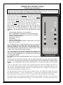
1
COUNTRY FLAME TECHNOLOGIES
INSTALLATION, OPERATION AND MAINTENANCE MANUAL
MODEL CF-04 CROSSFIRE STOVE
FIREPLACE INSERT, (FLEX FUEL VERSION)
USA & CANADA TEST:
TESTED BY:
ASTM E 1509-04, UL 1482,
WARNOCK HERSEY
ULC S627, ULC/ORD C1482 (and ULC S628
If listed for fireplace insert installation in Canada)
MOBILE HOME APPROVED
WARNING: If the directions in this manual are not followed exactly, a fire
may result causing property damage, personal injury or loss of life.
FOR YOUR SAFETY
Do not store or use gasoline or other flammables (vapor or liquids) in or
around the vicinity of this appliance.
Installation and repair must be performed by a qualified service agency.
Always check with local jurisdiction or code agency before installing this
product. Local jurisdiction may be requiring a permit prior to installation.
COUNTRY FLAME
© 2011
Version 2.0fc
1
SAFETY NOTES
The Crossfire Model CF-04 fuel stove is significantly different from a conventional wood-burning stove.
One major difference is that the CF-04 requires a reliable source of electrical energy to properly operate.
The owner, installer, and operator must understand this manual and read it in its entirety.
Understanding this manual should be completed and followed before installation or operation of the
CF-04 is attempted. Failure to follow installation and operation instructions or perform necessary
maintenance can result in property damage, bodily injury, or even death. Country Flame strongly
recommends that a certified professional install the Crossfire Model CF-04.
WARNING:
THE AUTHORITY HAVING JURISDICTION (such as a municipal building
department, fire department, or fire prevention bureau, etc) SHOULD BE CONSULTED
BEFORE BEGINNING INSTALLATION. A PERMIT MAY BE REQUIRED IN
ORDER TO PERFORM INSTALLATION.
WARNING:
A smoke detector is recommended to be installed in the vicinity of the Crossfire CF-04.
WARNING:
Country Flame Technologies has no control over installation or maintenance procedures;
therefore, Country Flame grants no warranty, implied or written, for the installation or
maintenance of the CF-04. Further, Country Flame assumes no responsibility for any
consequential damage resulting from said installation or maintenance of this product.
WARNING:
After operation, always allow the Crossfire stove to completely cool before performing
any maintenance operations.
WARNING:
The Crossfire stove requires reliable electric energy to properly operate. If electrical
power is not available, DO NOT operates the Crossfire with only a natural draft.
WARNING:
Only a certified professional should install a Crossfire stove. Only a qualified service
technician should perform maintenance on the Crossfire. Parts removed for installation or
servicing must be replaced prior to operational use of this stove.
WARNING:
Modification of the Crossfire is not authorized and any modification to the Crossfire voids
Country Flame’s product warranty.
WARNING:
The Crossfire must be connected to a code compliant grounded 120-volt, 15 ampere, and
60 hertz electrical outlet. Use of a dedicated circuit is recommended. NEVER use an
adapter, extension cord or cut or remove any prong from the power cord.
WARNING:
NEVER place or store any combustible or flammable products on or near the Crossfire.
WARNING:
The Crossfire is designed to shutdown in the event the front door is opened. Keep the
viewing door tightly closed during operation. Always clean the Crossfire after the stove
has been allowed to return to normal room temperature.
WARNING:
Do not connect the Crossfire to a chimney flue serving another stove of any type and
never install a flue damper in the exhaust system of the Crossfire.
WARNING:
FOLLOW all operating instructions in this manual. Short cuts in operating procedures,
of any kind, can be dangerous.
Version 4.0
2
WARNING:
Maintain all minimum safety clearances of the Crossfire stove and chimney system.
Never install the Crossfire in a sleeping room.
WARNING:
The Crossfire-Flex is designed and approved for burning of number 2 yellow shelled corn
with a maximum moisture content of 14% (10%-12% recommended) or industry approved
wood pellet fuel. Any fuel used in this stove must meet or exceed APFI standards. Do not
burn untested fuels or foreign materials in this product. Failure to comply with fuel
restriction voids Country Flame’s warranty and the safety listing of the unit. Poor quality
fuel will directly (and adversely) affect efficiency and cleanliness of operation. Country
Flame’s local authorized dealer can help in recommending a quality fuel
WARNING:
NEVER use gasoline, lantern fuel, kerosene, charcoal lighter fluid or other combustible
liquids to start or “freshen up” the fire in this product. Do not store or use gasoline or
other flammable liquids or allow combustible vapors in the vicinity of product.
WARNING:
NEVER put foreign objects in the hopper and NEVER burn trash or unapproved material
in the Crossfire. Using fuels other than #2 shelled corn or premium hardwood pellet
mixed with corn voids the Country Flame warranty. Damage to the stove resulting from
foreign objects is not covered by warranty.
WARNING:
Ensure free and adequate airflow to and around the Crossfire. This stove is a combustion
system that requires continuous flow of fresh air for proper operation. Failure to provide
an adequate fresh air supply can lead to operational problems such as: negative pressure
in the home, poor operation of this or other home combustion appliances, or a host of
other issues. Remember that other combustion appliances in the home compete for fresh
air. Consult with a professional to ensure positive air flow is provided to the stove during
operation.
WARNING:
The Crossfire’s exhaust system works with a negative combustion chamber pressure and a
low positive chimney pressure. It is very important that the Crossfire’s exhaust system be
airtight and properly installed. All exhaust joints connected to the Crossfire or each flue
section is to be sealed. Use 500 degrees Fahrenheit (500OF or 260 OC) silicone sealant or
aluminum high temperature tape and secure each joint with (3) sheet metal screws. An
improperly installed stove or chimney system is the major cause of home fires.
WARNING:
When installed in a mobile home, the Crossfire must be electrically grounded to the steel
chassis of the mobile home. In addition, the stove must be bolted to A NONCOMBUSTABLE FLOOR floor. A mobile home installation of the Crossfire should be
in accordance with the Manufactured Home and Safety Standard (HUD), CFR 3280, Part
24. Consult the local code authority.
WARNING:
SOOT AND FLY ASH: The products of combustion will contain small particles of fly
ash. The fly ash will collect in the exhaust venting system and restrict the flow of the flue
gases. Incomplete combustion, such as occurs during start-up, shut down, or incorrect
operation of the Crossfire will lead to soot formation in the exhaust venting system. Use
the Crossfire cleanout ports to clean the exhaust venting system at least twice every year.
WARNING:
ASH REMOVAL: The ash should be emptied every day or as required to ensure proper
operation. If the ash compartment is not emptied regularly, ash will build up and restrict
the flow of fresh air in the combustion chamber. The airtight seal of the viewing door
ensures a proper combustion process per the stove design and it should not be open during
normal operation of the stove.
Version 4.0
3
CAUTION:
Operate the Crossfire with the fuel hopper lid closed at all times. Failure to keep the
hopper lid closed during operation may result in the release of combustion gasses into the
home from the hopper under certain conditions. Maintain the Crossfire hopper seal in
good condition and do not overfill the hopper.
CAUTION:
The stove controls the rate of fuel fed into the fire pot. Never do anything to overfeed fuel
or cause over firing of the Crossfire.
CAUTION:
THE CROSSFIRE IS HOT WHILE IN OPERATION. DO NOT TOUCH. KEEP CHILDREN,
CLOTHING, AND FURNITURE AWAY. CONTACT WITH HOT SURFACES MAY CAUSE
SEVERE SKIN BURNS. REFER TO THE SAFETY LABEL FOR INSTRUCTIONS.
NOTE:
RETAIN this MANUAL for future reference as needed. Ensure the manufactured date
and serial number of the Crossfire are written down for use should maintenance be
required.
EPA STANDARDS
The Country Flame Crossfire meets rigorous emission standards. All Country Flame Crossfire Model CF04 stoves conform to United States Environmental Protection Agency standards.
LISTING/TESTING AGENCY
The Crossfire Model CF-04 has been independently tested and listed in accordance with ASTM E1509-04,
UL 1482, ULC S627, ULC/ORD C1482 (and ULC S628 if listed for fireplace insert installation in
Canada) and Oregon Administrative Rules 814-23-900 – through 909. This listing is for installation into
residential dwellings, including standard construction units, mobile home units, or modular home units.
The Crossfire Model CF-04 was tested to UL standards by Intertek Testing Services, NA, Inc., 8431
Murphy Drive, Middleton, WI 53562.
Version 4.0
4
CERTIFICATION SAFETY LABEL (sample)
Version 4.0
5
TABLE OF CONTENTS
SAFETY NOTES.........................................................................................................................................2
EPA STANDARDS ..................................................................................................................................4
LISTING/TESTING AGENCY ................................................................................................................4
CERTIFICATION SAFETY LABEL (sample) .......................................................................................5
TABLE OF CONTENTS............................................................................................................................6
FORWARD..................................................................................................................................................8
COUNTRY FLAME .................................................................................................................................8
CROSSFIRE LIMITED WARRANTY ...................................................... Error! Bookmark not defined.
CROSSFIRE LIMITED WARRANTY (continued).................................. Error! Bookmark not defined.
THE CROSSFIRE OPERATION ...........................................................................................................12
FEATURES.............................................................................................................................................12
SAFETY FEATURES.............................................................................................................................13
BATTERY BACKUP SYSTEMS ..........................................................................................................13
FUEL REQUIREMENTS .......................................................................................................................14
CROSSFIRE STARTUP ......................................................................... Error! Bookmark not defined.
ASH REMOVAL ....................................................................................................................................16
Intelli-Choice CONTROL BOARD ........................................................................................................16
CONTROL BOARD FACE ILLUSTRATION ………………………………………………………..20
CONTROL BOARD TROUBLESHOOTING CODES………………………………………………..23
STOVE ELECTRICAL DIAGRAM …………………………………………………………………..25
STOVE SPECIFICATIONS ...................................................................................................................25
ELECTRICAL REQUIREMENTS.........................................................................................................25
GOLD DOOR CARE ..............................................................................................................................25
OPTIONAL FEATURES........................................................................................................................25
OPTIONAL THERMOSTAT OPERATION..........................................................................................25
CROSSFIRE IS COLD .......................................................................................................................25
CROSSFIRE IS HOT..........................................................................................................................25
CHANGE HEAT LEVEL (thermostat active) ....................................................................................25
CHANGE HEAT LEVEL (thermostat inactive).................................................................................26
COMBUSTION FRESH AIR CONTROL .............................................................................................26
INSTALLATION ......................................................................................................................................27
INSTALLATION PREPARATION .......................................................................................................27
STOVE CLEARANCES .........................................................................................................................27
SHROUD INSTALLATION...................................................................................................................28
CHIMNEY ..............................................................................................................................................29
FACTORY-BUILT CHIMNEY..............................................................................................................29
MASONRY BUILT CHIMNEY.............................................................................................................29
FLOOR PROTECTION REQUIREMENTS ..........................................................................................30
OUTSIDE AIR COMBUSTION.............................................................................................................31
MOBILE HOME INSTALLATION .......................................................................................................32
Version 4.0
6
MOBILE HOME RULES .......................................................................................................................32
MOBILE HOME CLEARANCES..........................................................................................................32
MOBILE HOME STOVE ATTACHMENT...........................................................................................33
MOBILE HOME FLOOR PROTECTION .............................................................................................33
MOBILE HOME CHIMNEY AND DUCTS..........................................................................................34
MAINTENANCE REQUIREMENTS ....................................................................................................37
GENERAL REQUIREMENTS...............................................................................................................37
STOVE DOOR INSTALLATION..........................................................................................................37
STOVE DOOR ADJUSTMENT.............................................................................................................38
STOVE DOOR GLASS CLEANING.....................................................................................................38
GLASS REPLACEMENT ......................................................................................................................38
GLASS-CERAMIC SPECIFICATIONS ................................................................................................39
GASKET REPLACEMENT ...................................................................................................................39
CROSSFIRE CLEANING ......................................................................................................................39
APPENDIX A: TROUBLESHOOTING GUIDE..................................................................................42
APPENDIX A: TROUBLESHOOTING GUIDE (CONT’D) ..............................................................43
APPENDIX B: MAINTENANCE GUIDE.............................................................................................44
APPENDIX B: MAINTENANCE GUIDE (CONT’D) .........................................................................45
APPENDIX B: MAINTENANCE GUIDE (CONT’D) .........................................................................46
APPENDIX C: TECHNICAL SPECIFICATIONS ..............................................................................47
APPENDIX E: COMBUSTION BASICS ..............................................................................................48
APPENDIX F: REPLACEMENT PARTS ............................................................................................52
REPLACEMENT PARTS ......................................................................................................................52
REPLACEMENT PARTS ......................................................................................................................53
APPENDIX G: LABELS .........................................................................................................................54
REPLACEMENT LABELS....................................................................................................................54
REPLACEMENT LABELS.................................................................... Error! Bookmark not defined.
Version 4.0
7
FORWARD
COUNTRY FLAME
Country Flame has worked for over two decades in researching and developing biomass fuel burning
stove products. In 2002, Country Flame received a national award from the Hearth Industry for its
HARVESTER freestanding biomass fuel stove. Country Flame has now added the CROSSFIRE
FIREPLACE INSERT biomass fuel stove to its line of products. The CROSSFIRE gives every
homeowner the opportunity to convert their inefficient fireplace into a highly efficient heating machine.
In addition, the CROSSFIRE ensures that the homeowner can choose from an ever growing array of fuel
products to meet their home heating needs. Country Flame is dedicated to researching and developing
advanced pellet stove products capable of burning a wide variety of biomass fuel. The Crossfire Model
CF-04 was designed to burn APFI approved wood pellets or shelled corn. Switch grass pellets and other
fuel may be burned in the Crossfire but results have not been verified.
THE PURCHASE OF A COUNTRY FLAME CROSSFIRE BIOMASS FUEL STOVE IS A VOTE TO
REDUCE AMERICA’S DEPENDENCE ON FOREIGN OIL. Country Flame is very proud of this
American born, American tested, and American made product. With pride and dedication, Country Flame
employees wish you and your family a lifetime of happiness and warmth through the use of our products.
LET US PUT A FLAME IN YOUR HEARTh!
Version 4.0
8
AMERICAN ENERGY SYSTEMS INC. LIMITED PRODUCT
WARRANTY
This warranty is in effect on all products sold after 01/01/2009 and supersedes any and all warranties currently
in existence.
Please keep a copy of this warranty for your personal records or in the event of a claim
American Energy Systems Inc., hereinafter referred to as (AES), warrants to you, the original consumer purchaser,
that this product is free from defects in material and workmanship for a period of five (5) years from the original
purchase date minus any time past one (1) year from manufacturing date, and that the product’s electrical parts and
steel firepot, are free from defects in material and workmanship for a period of one (1) year from the original
consumer purchase date minus any time past one (1) year from manufacturing date, and that the cast iron firepot
models carry a lifetime warranty against defect in material or workmanship (excluding war page or deterioration),
and that door glass carries a lifetime replacement warranty against heat breakage (does not cover accidental
breakage) . There is expressly no warranty on installation of product, any venting, grates, gaskets, door latches,
insulation, ceramic or brick boards/logs/backing, paint, plated surfaces/doors/trims, baffles, bushings, bearings,
auger flightings, war page or discoloration of steel or plated parts or any other normal wearing part. In the event the
product fails to conform to this warranty, AES, through the place where you purchased the product or if purchased
on the AES E-Com store directly through AES, will provide the parts and components necessary to remedy such
nonconformity. AES will not be responsible for any labor, mileage or freight cost to the factory under this
warranty. This warranty is not transferable.
In order to obtain performance under this warranty, you must (1) have registered this warranty within 30 days of
purchase by completing and returning the warranty registration card or filling in the on-line warranty registration
form at www.magnumheat.com, and (2) promptly report the claimed nonconformity to your place of purchase,
also providing your name, address, phone number, proof of purchase, date of purchase, the model and serial
number of the stove, digital pictures of installation and venting inside and outside of the home, pictures of the
claimed nonconformity part and the claimed nonconformity. All claims must be submitted in writing to your
place of purchase.
AES shall have no warranty obligations if this product; (1) was not purchased from an authorized AES dealer; (2)
was not installed by a AES dealer or other qualified installer; does not have outside combustion air hooked directly
to the unit; (3) was not operated and maintained in strict accordance with the manufacturer’s instructions, local or
national codes or (4) was subject to abuse, misuse, negligence or accident. AES shall have no warranty obligation
for damage caused by improper handling, freight damage (must be reported to freight provider), over-firing,
unapproved fuel, variance in feed rates, variances in BTU output or the unauthorized disassembly or modification
of the product. AES shall have no warranty obligation if this warranty is not timely registered, for claims which are
not submitted through the selling AES dealer, or for claims submitted verbally or without the required information
and documentation.
Before exercising this warranty, an AES representative (the place where the product was purchased or AES
approved person) must inspect the part/unit to determine if the part/unit is defective. If a local AES representative
is not available the original purchaser of the product must submit digital pictures of the part/unit, installation of the
unit to AES at [email protected] If the inspection reveals that the failure is due to defective material or
workmanship and the part is covered by the conditions of this warranty, AES will, at its option, repair the defective
part/unit. The sole duty of AES and liability under this warranty is limited to the repair of the covered defective
part/unit. The purchaser shall assume all costs related to shipping the replacement parts or return of the unit to the
factory for repairs. If it is determined that the defect was caused by AES, AES will cover the costs of shipping the
repaired part/unit to an AES approved shipping point. AES will not cover additional freight or delivery services
such as residence delivery charges, special handling, etc.
INSTALLATION, VENTING, REMOVAL OR REINSTALLATION COSTS ARE NOT COVERED BY
THIS WARRANTY.
THE WARRANTY PRINTED ABOVE IS THE ONLY WARRANTY APPLICABLE TO THE
PRODUCT. ALL OTHER WARRANTIES, EXPRESSED OR IMPLIED, INCLUDING, WITHOUT
LIMITATION, THE IMPLIED WARRANTIES OF MERCHANTABILITY AND FITNESS FOR A
Version 4.0
9
PARTICULAR PURPOSE, ARE DISCLAIMED. IT IS UNDERSTOOD AND AGREED THAT
AES’S LIABILITY UNDER THIS WARRANTY SHALL BE LIMITED TO THE PROVISION OF
REPLACEMENT PARTS AND SHALL NOT INCLUDE LIABILITY FOR SPECIAL, INCIDENTAL
OR CONSEQUENTIAL DAMAGES. ANY ACTION BROUGHT UNDER THIS WARRANTY
MUST BE BROUGHT WITHIN ONE YEAR OF THE ACCRUAL OF THE CAUSE OF ACTION
AND MAY ONLY BE BROUGHT IN THE CIRCUIT COURT OF MCCLOUD COUNTY,
MINNESOTA.
Some states do not allow limitations on how long an implied warranty lasts or the exclusion or limitation of incidental or
consequential damage, so the above limitations may not apply to you. This warranty gives you specific legal rights, and you
may also have other rights which vary from state to state.
ALL WARRANTY CLAIMS MUST BE SUBMITTED IN WRITING THROUGH THE PLACE WHERE THE
PRODUCT WAS PURCHASED. In the event where the place of purchase has ceased business or if you feel that
there is a legitimate reason that you cannot submit your claim to the place where the product was purchased you
may make a written request to the factory by emailing your request along with all of the required information to
[email protected] . NOTE: Verbal requests will not be recognized. If it is determined that
warranty could have been performed by the place of purchase, the factory will deny the claim.
Included with the claim must be the following information: (if this information is not complete, the claim will be
denied)
Name, address, telephone number, email address, of place of business where product was purchased &
also purchaser contact info.
Date of purchase, model and serial number of product, digital pictures of product (front, sides, back,
venting inside and outside)
(If there is ductwork, there must be digital pictures of entire ductwork installation, static pressures, air
flow measurements, and contact information of licensed/factory certified contractor that installed unit)
Nature of defect, what has been serviced (service record), who installed product along with contact
information.
Version 4.0
10
Place
Stamp
Here
American Energy Systems, Inc
150 Michigan Street SE
Hutchinson, MN 55350
Fold Here
Name
City
Dealer
Dealer’s Name
City
Date of Purchase
Model No.
Address
State
Zip
State
Zip
Serial No.
The express warranties made by Country Flame Technologies do not apply unless this warranty card
is received by Country Flame Technologies from the original retail purchaser no later than thirty
(30) days subsequent to the date the Country Flame product was originally purchased.
Date
Signature
Version 4.0
11
THE CROSSFIRE OPERATION
FEATURES
Country Flame designed and built the CF04 stove to burn 100% shelled corn. Unlike conventional pellet
stoves, the Crossfire was designed to handle large amounts of ash. This means the Crossfire is capable of
burning corn or a mix of wood pellets and corn while reducing the possibility of choking the fire from ash
residue. Country Flame is pleased that customers are finding wide success in burning locally available fuels
but Country Flame cannot support or warranty the burning of untested fuel in the Crossfire.
Before beginning to install or operate the Model CF-04 Crossfire, please consult with the local building
authority to obtain a permit and ensure a professional installs or certifies the installation of this product.
Before a homeowner operates this stove, a thorough operational understanding should be obtained from
reading and understanding this manual. Failure to adhere to all safety notes and instructions contained herein
can impact homeowner insurance, void warranty, and create hazardous situations leading to a smoke damage,
fire, or even death.
The Model CF-04 was designed as a insert only model stove. The Crossfire was designed to be installed into
an existing zero clearance fireplace or an existing masonry fireplace. There are no leg or pedestal base
options for the Crossfire. Contact Country Flame or one of its local authorized dealers to discuss and select
possible options that are available for the Crossfire. Once installed, the Crossfire is remarkably simple and
safe to operate. FIGURE 1 and FIGURE 2 defines Crossfire components. From a relatively small firebox the
Crossfire generates a very beautiful flame with lots of heat being produced into the room where the unit is
installed. Clean AFPI approved fuel is to be loaded into the hopper. A motor turns an auger that delivers fuel
to the combustion chamber on a timed basis. Corn or pellet fuels can be fed into the Crossfire burn pot.
FIGURE 1: CROSSFIRE MODEL CF04
Version 4.0
12
FIGURE 2: CROSSFIRE COMPONENTS
SAFETY FEATURES
The Crossfire comes standard with a number of advanced safety features; however, to ensure maximum safety
install the stove according to all national and local codes and follow all operating and maintenance
procedures. The Crossfire requires a fresh air supply to ensure proper combustion. This fresh air is used in
the combustion process to achieve thorough burn of all fuel. The Crossfire needs a sealed and properly
designed exhaust flue system. This exhaust flue will be used to remove combustion gasses outside the home.
REMEMBER: one of the leading causes of house fires is due to improper installation or improper operation
of a stove product. Proper installation and operation of the Crossfire is required to obtain Homeowner
insurance coverage. And, the Crossfire needs a reliable source of electrical power. Without reliable utility
power or a means to ensure reliability, the Crossfire operation will be problematic.
It will require some effort and learning for the homeowner to thoroughly understand the operating
characteristics of the Crossfire. More importantly, the operator needs to know how to control each one of the
stove’s operations. The Crossfire has an electronic control system whose “brain” is constantly monitoring
stove operations in order to ensure fuel combustion efficiency and to ensure maximum heat output of this
product. The Crossfire’s electronic control provides a simple one stop location for the homeowner to control
Crossfire performance. To ensure safe operation, the Crossfire’s electronic control is constantly monitoring
pressure and heat activated switches, and input power to ensure proper operation. Additional features include
an enclosed firebox, high temperature ceramic glass, optional thermostatic control, a high temperature wiring
harness, making the Crossfire an extremely safe stove.
BATTERY BACKUP SYSTEMS
The Country Flame Crossfire Model CF04, relies on electrical energy (wall power outlet) to properly operate.
Without electrical energy or with interruptions to the source of electrical energy, the Crossfire stove’s
operation will be erratic at best. Is power quality, power reliability, or routine winter storm conditions a cause
of power problems in a specific locale? If it is, the homeowner will need to provide backup power to ensure
Version 4.0
13
stable operation of the Crossfire. Fortunately, there are simple, reliable, and cost effective power backup
solutions available. Today, a homeowner can choose from a variety of power conditioning systems from a
number of “big box” retail stores. For example, Home Depot, Circuit City, Best Buy, Wal-Mart, or other
stores carry standard power conditioning equipment. Two good quality power conditioning equipment
manufacturers are APC and TrippLite. These uninterruptible power supplies (UPS) include the capability to
handle power failures, brown outs, power surges, line noise, and sell for around $35 to $150. UPS system
cost is largely defined by the features included and the amount of time (battery size) the UPS can operate
before recharging of the battery is required. UPS systems are sold by the number of electrical outlets, the
volt-amperes (watts), and the additional features included.
FUEL REQUIREMENTS
The Crossfire Model CF04 was designed to burn #2 shelled corn, or any mix of both corn and Premium
Hardwood Pellets. The corn’s moisture content should be limited to no more than 14% moisture content.
Country Flame recommends corn fuel moisture content be maintained somewhere in the range of 10% to
12%. USING SEED CORN AS FUEL IS DANGEROUS TO OCCUPANTS. BURNING SEED CORN
VOIDS THE COUNTRY FLAME WARRANTY.
If pellet fuel is added to the corn in the Crossfire, Country Flame recommends no more than 8% moisture
content. The American Pellet Fuel Institute establishes standards for pellet fuel manufacturer’s product.
Pellet Manufacturers voluntarily follow these standards but homeowners should know what to look for. The
following terms should be understood by the homeowner:
ASH: Biomass stoves produce two kinds of ash:
1) Solid ash residue in the firepot; and
2) Fly ash (un-burnt particles) and air born fly ash (sparklers) are created during the combustion process. The
Crossfire has an ash compartment which aids in cleaning the stove. Ash can also accumulate in "ash traps"
which need to be cleaned periodically. The remaining fly ash is blown into the flue system which will also
require periodic cleaning.
FINES: (sawdust): Fines are caused by pellet disintegration that occurs during transport or storage of pellets.
Two potential problems – fines can create dust in the home and fines cause interference to the flow of pellets
in the fuel hopper.
BTU's: (heat) PER POUND: The variation of BTU's per pound in pellet or corn fuel is usually not noticeable
to most users. Overall stove efficiency (combustion efficiency times heat transfer efficiency) has a greater
impact on the heat delivered to the home.
DENSITY: Pellet density (measured in pounds per square foot) determines the maximum amount of energy
that can be delivered to the combustion chamber. Low density fuels may cause the fire to go out on low heat
settings without proper adjustments to the air-to-fuel ratio.
SALT: Salt in pellets can cause stove deterioration (rust). The Pellet Fuels Institute is participating in tests to
determine the effects of salt and the most accurate methods of measurement. The APFI will publish standards
that will result in recommended standards for sodium in pellets.
CLINKERS: Clinkers are the result of impurities in pellets or corn. Clinkers may also occur due to ash
fusion (ash melted together in the burn pot), and can be minimized by properly adjusting the air-to-fuel ratio.
DIRTY GLASS: Glass becomes dirty during normal or faulty combustion. Some fuels produce a film on the
glass to which ash adheres, making a clean glass more difficult.
Pellet fuel manufacturers should be able to show test results for BTU's, ash content, and the amount of fines
in their product. Do not hesitate to contact the pellet manufacturer if you have questions or concerns. If
questions remain about the Crossfire, please contact a local authorized Country Flame Dealer for assistance.
Version 4.0
14
OPERATING REFERENCE GUIDE
CROSSFIRE – FLEX STOVE (SEE FIGURE #3)
• DO NOT use any other ignition accelerant other than igniter/burn gel or igniter
blocks to start or enhance the fire in the Crossfire stove.
• FUEL the only fuel the CF04 stove is designed to burn is #2 shelled Corn (10-12%
moisture) or any mix of Corn and Premium Hardwood Pellets. It is highly
recommended that the corn be “CLEANED” (free of dust, fines, & any other foreign
matter) for optimum stove performance. Burning SEED CORN as fuel is extremely
dangerous to occupants and voids the Country Flames warranty.
• To enhance the initial start-up fire, manually rotate the stir rod occasionally. This is
done by pressing, and holding down both the “UP and “DOWN” arrow keys on the
control board at the same time. This will mix the burning pellets, speeding up the burn
process. Note: It rotates at only 1 RPM.
• NOTE: If the system does not come on after doing Step #6 per the start-up guide it
is because the stove temperature is not hot enough. Carefully open the door and
manually add more pellets to the fire, repeat step #6. Once the system comes on and is
automatically set to heat setting #3, allow the stove adequate time to burn and heat up
properly (approx 30 min.) before changing settings. If a heat setting change is made
more than one bar at a time, (red and blue arrow keys) there is a 2 minute response
delay in the fan speed for each level increase. Adjust the inlet air control as
required to sustain even continuous burn.
• INLET AIR Make small, slow incremental changes in the air control. If to much
air is given, it will cool the corn below its ignition point and the fire will go out.
The higher the heat level setting on the stove the more inlet air required for a
complete burn of the Corn. Setting No# 5 will require a little more air than setting
No#1. Adjust the inlet control lever accordingly. (To the front of the stove is
CLOSED, see manual for illustration)
• A visual reference to the Ideal burn condition of Corn would show a fuel level in the
Burn-Pot “BELOW” the stir rod at ALL TIMES. This will prevent any possibility
of an over feed condition. The fuel feed rate can be regulated by the potentiometer on
the back of the control board. (See manual)
• STOVE SHUT-DOWN PROCEDURE, during normal operation, simply push the
“ON/OFF” control button, (bottom of the control pad) and hold it for approx. 5
second.
• All questions or concerns about lighting or other stove operational issues should be
directed to your local Country Flame Dealer.
Version 4.0
15
The stir rod will be controlled by the control board. This stir rod assists in mixing fuel with air in the burn
pot. The stirring action improves the mixing of oxygen and fuel and accelerates the combustion process. As
heat settings are changed on the control board, the stir rod speed will automatically be adjusted to more
closely match the feed rates of the different heat settings.
The stir rod assists in minimizing “clinker” build-up in the burn pot. If the proper air-fuel mixture is set by
the homeowner, the Crossfire will generate a very fine ash rather than clinkers. In addition, the stir rod
ensures that the fuel and flame are constantly agitated within the burn pot to enhance the combustion process.
The Crossfire burn pot has been designed to ensure maximum efficiency of burn while minimizing the
amount of ash being produced at the same time minimizing the clinkers that might choke out a fire. Testing
by Country Flame has shown that the Crossfire can be continuously operated for several days without
requiring cleaning. However for optimum stove performance, make sure all air passages and burnpot are free
of obstruction. It should be recognized by the homeowner that environmental variables as well as the type of
fuel being burnt can have dramatic effect on the amount of ash or clinkers formed during the burn cycle.
Burn pot cleaning will depend upon the quality, quantity, and moisture content of the fuel. Ash removal will
be required from time to time depending on the amount of usage and the heat output required. The Crossfire
stove should be shut down and cooled before cleaning or removing any ash from the firebox.
CLEANING - ASH REMOVAL
The Crossfire stove has a deep ash container built into the firebox. There is no removable ash pan located
within the Crossfire. This means the operator must allow the ash to properly cool and then vacuum the ash
from the stove and BURNPOT with an industry approved ash vacuum. Once the ash has been removed from
the firebox, it should be stored or disposed of in proper containers. Failure to properly handle ash, even when
the ash is believed to be completely cool, can lead to a fire.
Always remove ashes after they have been allowed to cool properly. Hot ash is dangerous to both
surrounding areas and occupants and can cause fires or severe burns. Wait until the fire has been out for
several hours before vacuuming the firebox with an industry approved ash vacuum. Protective gloves should
be worn anytime ash is removed. Dump all ash into a proper ash container and remove to a safe outdoors
area. Remember that although the ash may look and feel cool to the touch, a smoldering ember can start a
fire. CAUTION: Care should be used to store any ash in a proper container with an approved airtight lid. If
ash is taken outside, water should be poured over the ash to ensure no fire flare up can occur.
CONTROL BOARD
In 201 Country Flame introduced its own control board technology control board technology was introduced
across all pellets and corn stove product lines. The control board is being used exclusively on Country Flame
product. This control board technology was developed to ensure better support to customers. Country Flame
will seek to provide the most advanced controls while maintaining the look and feel our dealers and
customers have come to know and expect. Country Flame also wants to ensure its product can be upgraded to
newer and more advanced technology if and when this technology becomes available and the customer
chooses to obtain it. Country Flame is committed to its customer base. Country Flame will strive to make the
service support process easier through systematic troubleshooting procedures and repair events that should
allow for evolving “plug n play” operations. Country Flame’s goal is to ensure a certified service technician
can diagnose and repair any stove problem in less than 30 minutes. FIGURE 4A depicts control board basic
theory and FIGURE 4B provides a brief description of sensor controls.
Version 4.0
16
VACUUM
SENSOR
OVERTEMP
SENSOR
INPUT VOLTAGE
120 Volts AC 60 Hz
15-Ampere Circuit
FUEL
CONTROL
COMBUSTION
AIR CONTROL
Hopper Switch
THERMOSTAT
(Optional)
CONTROL BOARD
ON/OFF SWITCH
TEMPERATURE CONTROL
POWER/FUEL/IGNITER/ INDICATORS
Fuse
6–9
Amperes
STOVE
EXHAUST
TEMPERATURE
SENSOR
ROOM
AIR
TEMPERATURE
SENSOR
ROOM AIR
CONTROL
STIR ROD
FIGURE 4A: CONTROL BOARD BLOCK DIAGRAM
Input Voltage
Fuse
Vacuum Sensor
Exhaust Temperature Sensor
Overtemp Sensor
Fuel Control
Room Air Control
Combustion Air Control
Stir Rod
Thermostat (optional)
Alternating Current (AC) Input provided by the local power company. This source of energy
must provide a 120 Volt input signal with a frequency of 60 Hertz and a maximum branch
current capacity of 15 Amperes. If other devices are connected to the branch, interference or
over current may cause circuit breaker to trip.
The AC fuse should be rated between 6 and 9 amperes. The recommended fuse is a Little
Fuse Model _______.
Ensures that no blockage of the combustion input or combustion exhaust air occurs. If the
vacuum sensor does not operate properly, the Control Board will not allow the stove to
operate.
Presently, this sensor is a snap disk operating at 110o F +/- 20o F. This sensor ensures proper
exhaust temperature has been reached and that a fire is present in the burn pot before the
control system begins the burn cycle.
Presently, this sensor is a snap disk operating at 250o F +/- 20o F. The purpose of this sensor
is to shut the entire system down in the event the firebox causes an overheat condition.
The fuel control is a signal provided from the Control Board to the Auger Feed Motor. The
Control Board controls the amount of time that the Auger Feed Motor is on and thereby
controls the amount of fuel fed to the fire pot.
The room air control is a signal provided from the Control Board to the Room Air Fan. The
Control Board controls the phase angle and thereby the amount and time an AC voltage is
applied to the Room Air Fan. This signal controls the speed of the room air passing over the
heat exchanger tubes and the amount of heat delivered to the living space.
The combustion air control is a signal provided from the Control Board to the Combustion
Fan. The Control Board controls the phase angle and thereby the amount and time an AC
voltage is applied to the Combustion Air Fan. This signal controls the speed of the
combustion air passing through the burn pot for the different heat settings
An AC device used to create turbulence in the burn pot. The stir rod reduces the potential of
a klinker thereby ensuring more efficient combustion process. The operator must remove and
clean the stir rod from time to time. Be careful not to damage or break the stir rod.
A thermostat input is provided on the back of each Country Flame product. The Control
Board has individual personality modules that allow for stand-alone, semi automatic, or fully
automatic thermostat operation.
FIGURE 4B: STOVE COMPONENT DEFINITIONS
Version 4.0
17
FIGURE 5 displays the Country Flame Control Board front panel. Each function of the Control Board is
identified.
Power- on light glows
amber when on
Heat level indictor LED
(red per heat level setting)
Auger feed light
(amber when on)
Manual, Thermostatic
operation mode button
Heat level (up) adj.
button
room air adjustment
button
Heat level (down)
adj. button
Auger trim
Adjustment button
Exhaust/Draft Blower
trim adjustment button
ON/OFF control
button
Please NOTE:
Version 4.0
18
OPERATING INSTRUCTIONS
(Using self igniter systems, if auto ignition system (optional) has been installed)
NOTE: Each time the stove is started, the firepot must be checked for debris and clear air holes. Some
fuels will cause the firepot to build up more frequently making it necessary to stir and clean the firepot
more often. Do not allow ash to build up underneath the firepot area or in the ash pan as it will block
off the air flow to the firepot.
Your control panel has three (3) separate modes of operation (switch located on top of board). The
MANUAL setting allows the operator to choose heat level setting changes without a thermostat. The TSTAT setting allows the operator to set the highest heat level setting desired and when the thermostat is
satisfied, the unit will automatically go to the low heat level setting. The AUTO setting allows the unit to shut
completely off when the thermostat is satisfied and re-start when the thermostat calls for heat. The AUTO
setting can only be used with wood pellets or a 50/50 mix of corn and wood pellets.
Before lighting your Country Flame for the first time make sure that all items are out of the hopper and firebox
area. Note: If using a wall thermostat, make sure that the thermostat is turned up above room temperature. The
unit will operate on low fire if the thermostat is turned down.
9 Load the hopper with fuel (Corn or Wood Pellets).
9 Close the door
9 Push the “On/Off” button.
9 Turn the air intake butterfly damper to approximately ¼ inch open.
(More or less as needed.)
NOTE: Priming the auger is required when the unit is new or when the
hopper has completely run out of fuel. This can be done approximately 1
minute after pushing the on/off start button. Press and hold the “auger”
button until fuel begins to drop into the firepot. When fuel begins to drop
regularly, release auger button, the auger is primed.
NOTE: The viewing door, ash pan door and hopper door must be closed
and/or latched during operation or vacuum will not be established. If
vacuum can not be established the stove will shut down and the #2 heat
level setting light will blink. The ON/OFF button must be held for app. 6
seconds to reset.
The unit starts automatically on a pre-set heat level setting. After the unit
has been turned on, and the 1 minute diagnostics has run, you may select a
desired heat level. However, the heat level feed rate will not change until
the unit has completed the 15 minute startup sequence. It is recommended
to burn the unit on the number #2 or #3 heat level setting for the first 30-45
minutes.
If the fire temperature has not reached proper operating temperature
within the minimum cycle time (15 min.) the auger will stop feeding,
the stove will shut down and the #3 heat level setting light will blink.
You will need to press and hold the ON/OFF button for 6 seconds to
start the cycle over again. If the system is set on auto start it will
attempt two startups on its own.
The draft and room air blower speed varies with each feed rate. The
“Draft Trim” button will override the variable fan function +/- 5 volts on
all heat levels. To override, press and hold the “Draft Trim” button along with the heat level button arrow up
or heat level button arrow down, depending on desired change.
Version 4.0
19
The auger feed rate on each setting is pre-programmed but may be changed if necessary. The “Auger Trim”
button will override the programmed feed rates by +/-5% on all heat levels. To override the feed rate press
and hold the ‘Auger Trim’ button along with the heat level button arrow up or heat level button arrow down,
depending on desired change.
NOTE: In case of a power outage or interruption lasting longer than 5 seconds, the “On/Off” button
must be pushed and held for app. 6 seconds to re-engage the auger. If needed re-light the unit.
NOTE: If the fire is burning too fast and the fuel is being burned up too quickly, turn the air intake butterfly damper
closed a little to slow the fire down. This should be done in small 1/4” increments so that the fire doesn’t change too
quickly. You can also adjust the draft or auger trim to balance out the burn rate.
NOTE: When changing the heat levels there will be a delay so the system can complete the cycle before
switching to the new heat level.
NOTE: In case of a power outage, the pressure switch has tripped, the door has been opened, the
hopper door has been left open or any power interruption lasting longer than 5 seconds, the “On/Off”
button must be pushed and held for app. 6 seconds (or until you here a click) to re-engage the auger
system.
IMPORTANT: The circuit board will not function properly if the outlet is not a constant 120 volt, 60
cycle power source. The outlet must be grounded properly and have the correct polarity. A polarity
and ground tester can be picked up at any hardware store to assure proper operation. If you are using
a power generator, solar power or wind generation make sure that you have a constant correct power
source.
The unit’s electrical warranty would become void if a constant power source is not available. Also
make sure that a proper surge protector is between the unit and the power source. The circuit board
will not be warranted if there is not a surge protector installed to the unit.
It is strongly recommended that you unplug the power source during times when the unit is not being
operated to protect the unit from power surges, power spikes and drops in power. It is very common
for a circuit board to work when the unit is shut off in the spring and then won’t work in the fall.
Unplugging the unit will prevent this from happening.
Version 4.0
20
OPERATING INSTRUCTIONS
(Without using system igniter)
NOTE: Each time the stove is started, the firepot should be checked for debris and clear air holes.
Some fuels will cause the firepot to build up more frequently making it necessary to stir and clean the
firepot more often. Do not allow ash to build up underneath the firepot.
Your control panel has three (3) separate modes of operation (switch
located on top of board). The MANUAL setting allows the operator to
choose heat level setting changes without a thermostat. The T-STAT
setting allows the operator to set the high heat level setting and when
the thermostat is satisfied, the unit will automatically go to the low heat
level setting. The AUTO setting allows the unit to shut completely off
when the thermostat is satisfied and re-start when the thermostat calls
for heat. The AUTO setting can only be used with wood pellets.
Before lighting your Country Flame for the first time make sure that all
items are out of the hopper and firebox area. Note: If using a wall
thermostat, make sure that the thermostat is turned up above room
temperature. The unit will operate on low fire if the thermostat is turned
down.
9
9
9
9
9
9
9
Load the hopper with fuel (Corn or Wood Pellets).
Place a small handful of wood pellets or fire starter in the firepot.
Squirt a small amount of fire starter gel on top of the wood pellets.
(Evenly across the wood pellets)
Light the fire starter gel.
Close the door
Push the “On/Off” button.
Turn the air intake butterfly damper to approximately ¼ inch open.
(More or less as needed.)
NOTE: Priming the auger is required when the unit is new or when the
hopper has completely run out of fuel. This can be done approximately 1
minute after pushing the on/off start button. Press and hold the “auger”
button until fuel begins to drop into the firepot. When fuel begins to drop
regularly, release auger button, the auger is primed.
NOTE: The viewing door, ash pan door and hopper door must be closed
and/or latched during operation or the vacuum will not be established. If
vacuum can not be established the stove will shut down and the #2 heat
level setting light will blink.
The ON/OFF button must be pushed and held for app. 6 seconds to reset
the system.
The unit starts on a pre-set heat level setting. After the unit has been turned on you may select the desired heat
level. However, the feed rate heat level will not change until the unit has completed the 15 minute startup
sequence. It is recommended to burn the unit on the number #2 or #3 heat level setting for the first 30-45
minutes.
If the fire temperature has not reached proper operating temperature within the minimum cycle time (15
min.) the auger will stop feeding, the stove will shut down and the #3 heat level setting light will blink. You
will need to press and hold the ON/OFF button for 6 seconds to start the cycle over again. If the system is set
on auto start it will attempt two startups on its own.
The draft and room air blower speed varies directly with the feed rate. The “Draft Trim” button will override
the variable fan function +/- 5 volts on all heat levels. To override, press and hold the “Draft Trim” button
along with the heat level button arrow up or heat level button arrow down, depending on desired change.
The auger feed rate on each setting is pre-programmed but may be changed if necessary. The “Auger Trim”
button will override the programmed feed rates by +/-5% on all heat levels. To override the feed rate press
Version 4.0
21
and hold the ‘Auger Trim’ button along with the heat level button arrow up or heat level button arrow down,
depending on desired change.
NOTE: In case of a power outage or interruption lasting longer than 5 seconds, the “On/Off” button
must be pushed to re-engage the auger. If needed re-light the unit.
NOTE: If the fire is burning too fast and the fuel is being burned up too quickly, turn the air intake butterfly damper
closed a little to slow the fire down. This should be done in small 1/4” increments so that the fire doesn’t change too
quickly. You may also adjust the draft and auger trim to balance the burn rate.
NOTE: When changing the heat levels there will be a delay so the system can complete the cycle before switching to the
new heat level.
NOTE: In case of a power outage, the pressure switch has tripped, the door has been opened, the
hopper door has been left open or any power interruption lasting longer than 5 seconds, the “On/Off”
button must be pushed and held for app. 6 seconds (or until you here a click) to re-engage the auger
system.
IMPORTANT: The circuit board will not function properly if the outlet is not a constant 120 volt, 60
cycle power source. The outlet must be grounded properly and have the correct polarity. A polarity
and ground tester can be picked up at any hardware store to assure proper operation. If you are using
a power generator, solar power or wind generation make sure that you have a constant correct power
source.
The unit’s electrical warranty would become void if a constant power source is not available. Also
make sure that a proper surge protector is between the unit and the power source. The circuit board
will not be warranted if there is not a surge protector installed to the unit.
It is strongly recommended that you unplug the power source during times when the unit is not being
operated to protect the unit from power surges, power spikes and drops in power. It is very common
for a circuit board to work when the unit is shut off in the spring and then won’t work in the fall.
Unplugging the unit will prevent this from happening.
Before starting the Country Flame Biomass unit again, it is important to remember to clean out the firepot,
empty the ashes, clean out the heat exchangers, vacuum out the hopper if needed and fill the hopper with fuel.
Basic Circuit Board Functions (expanded)/Diagnostics
Operation
The ON/OFF button initiates the start of the circuit board and the shut down of
the board. Pushing the ON/OFF button momentarily will engage the start up
sequence. The ON/OFF button also is used to re-set the board when the vacuum
switch or proof of fire switch is tripped. Pushing the ON/OFF button until the
board re-sets (usually 6-7 seconds) will re-establish the system and the fire will
continue unless there is a failure in the electrical components.
When you push the ON/OFF button to start the unit, power light will be on and
the start up sequence will take approx. 12-15 min. During the start up sequence,
the fuel level setting will be over ridden and the unit will feed at the pre-set fuel
rate setting. After the start up sequence has been established (approx. 12-15 min.)
the unit will run at whatever fuel level setting you selected. The number #2 or #3
heat level setting is recommended for the 1st 30-45 minutes.
The auger light will flash when the auger is running. On the wood setting the
auger will start right away. If on the corn setting there is a (2) minute delay prior
Version 4.0
22
to starting. You can hold the auger button down to override the system and manually prime the auger.
The room fan button will override the # 1 heat level setting fan speed and go to high speed. This will not
change the fan speed on the #2 - #5 heat level settings.
The auger trim button allows for a low/high fuel setting fine tune adjustment on the all 5 settings. When
pushing the auger trim button select either the heat level up button or heat level down button depending on the
fine tune requirements.
The draft trim allows for a low/high setting fan speed and go to a lower or
higher setting depending on requirements. When pushing the draft trim
button select either the heat level up button or the heat level down button
to fine tune fan speed.
The heat level setting button is a manual heat adjustment. Pushing the
heat level setting button will advance the heat settings one level each time
that it is pushed. The LED light will show which heat level setting the
unit is on. At start up, regardless of where the heat level setting button is
set, the unit will feed on the pre-set heat level setting. Once the start up
sequence has been established, the fuel feed rate setting will run at
whatever fuel level setting you selected.
During a short power outage, the board will detect if the proof of fire
switch is engaged. If it is still engaged (closed) the unit will auto re-start.
Shutdown
To shut the unit down, simply press the On/Off button. The
room fan and exhaust blower will continue to operate until the
low limit/cool down sensor tells it that the fire is out. At that
point the exhaust fan will continue to run for an additional 15
minutes to make sure there is no exhaust in stove.
Your control panel comes with the ability to use ten (10) separate programming features. This programming
must be done by a qualified factory trained technician. Contact your local dealer to set up an appointment to
have this done. The unit also has three (3) separate modes of operation (switch located on top of board). The
manual setting allows the operator to choose heat level setting changes. The T-STAT setting allows the
operator to set the high heat level setting and when the thermostat is satisfied, the unit will automatically go to
the low heat level setting. The AUTO setting allows the unit to shut completely off when the thermostat is
satisfied and re-start when the thermostat calls for heat. This setting can only be used with wood pellets.
Version 4.0
23
AC MODEL WIRING DIAGRAM
WARNING: DISCONNECT POWER BEFORE SERVICING THIS UNIT.
Version 4.0
24
STOVE SPECIFICATIONS
TABLE 2 shows the physical dimensions of the Crossfire product.
CROSSFIRE
STOVE HEIGHT (At Front)
STOVE DEPTH (From Shroud)
STOVE WIDTH (Rear)
STOVE WIDTH (At Shroud Mount)
STOVE WEIGHT (empty)
SHROUD WIDTH, (standard)
SHROUD HEIGHT (standard)
SHROUD WIDTH, (oversized)
SHROUD HEIGHT (oversized)
DIMENSIONS (IN INCHES)
22.5“
14.0“
26.0“
25.5“
220 pounds
42.0”
30.0”
48.0”
32.5”
TABLE 2: CROSSFIRE-FLEX SPECIFICATIONS
ELECTRICAL REQUIREMENTS
The Crossfire Model CF-04 requires a code compliant grounded 120 volt, 15 ampere, and 60 hertz electrical
outlet. The Crossfire utilizes only a fraction of the 15 amperes rating of a code compliant outlet but it is
strongly recommended that a dedicated circuit (versus a branch electrical circuit) be provided for the stove to
ensure no interference from other electrical appliances.
GOLD DOOR CARE
All Crossfire plated doors and trim (gold or nickel) should be wiped down BEFORE THE FIRST FIRE to
prevent potential permanent damage to occur to plating. For general cleaning, use a dry cloth and wipe the
plated surface to ensure the luster and beauty lasts a lifetime. Always use an approved glass cleaner (i.e.
Windex, Glass Plus) and a lint free soft cloth to polish the doorframe. DO NOT use abrasives, like steel
wool, brass polish, or cleaners, like Comet. Improper cleaners can permanently scratch the finish. A
damaged door can be returned to Country Flame for refinishing but repair is expensive. Proper care of the
Crossfire plated door and other plated trim will ensure these parts will survive a lifetime of use. A painted
Crossfire door requires no specific care.
OPTIONAL FEATURES
There is an ever growing list of options for Country Flame stove products, including the Crossfire. Contact
an authorized Country Flame dealer for more information.
OPTIONAL THERMOSTAT OPERATION
A thermostat option is available for the Crossfire.
CROSSFIRE IS COLD
• See start-up procedure.
CROSSFIRE IS HOT
• If the stove is set to a heat setting greater than 1 when the thermostat calls for heat, the Intelli-Choice
Control Board will remember this setting and return to this setting any time heat is called for by the
thermostat.
• If the heat level is equal to 1 when the thermostat calls for heat the Intelli-Choice Control Board will
use this setting whether heat is called for or not.
• The stove will operate at the selected Heat Level until such time as the thermostat stops calling for
heat. The Intelli-Choice Control Board will then return the stove back to heat level 1. The last heat
level programmed by the operator will be remembered by the software for use as the next Thermostat
Heat Level when heat is again called for by the thermostat.
CHANGE HEAT LEVEL (thermostat active)
• When the homeowner changes the control board heat level setting, while the thermostat is active
(calling for heat,) the new setting becomes the new thermostat (call for heat) setting. The stove will
Version 4.0
25
•
move to that heat setting anytime the thermostat calls for heat. Otherwise, when the thermostat no
longer calls for heat, the control board sets the stove to Heat #1.
If the operator changes the heat level to 1 while the thermostat is calling for heat, it will become the
new Thermostat Heat Level. But because this is the same setting as when the thermostat stops calling
for heat, the operator will get no indication that the thermostat is in control of the stove.
CHANGE HEAT LEVEL (thermostat inactive)
• If the operator makes a change to the heat level while the stove is inactive, the stove will move to that
level. The next time the thermostat calls for heat, the most recently programmed heat level will
become the Thermostat Heat Level and the stove will operate at that point until the thermostat no
longer calls for heat.
FIGURE 10: CROSSFIRE COMBUSTION FRESH AIR CONTROL
COMBUSTION FRESH AIR CONTROL
Combustion fresh air can be controlled on the Crossfire. This optional control assists in optimizing the burn
rate of the fuel. All air entering the firebox is controlled with this fresh air control system. A control lever as
shown in figure #10 above, open and closes the inlet air damper. This air control should allow the homeowner
the ability to adjust for any variation in fuel to ensure an efficient burn. By opening or closing this baffle the
amount of fresh air allowed into the combustion chamber can be controlled. If the fresh air is connected to a
pipe leading outside the house, the fresh air control should be kept in the closed condition to minimize air
infiltration into the home when the Crossfire stove is not in use.
Version 4.0
26
INSTALLATION
INSTALLATION PREPARATION
Country Flame strongly recommends the Crossfire be installed by a certified professional. Improper
installation will create long-term operational and maintenance problems that will plague the homeowner
until corrected. The first step is to ensure all necessary parts are available to complete a proper
installation. Country Flame recommends a homeowner purchase the Crossfire from an authorized
dealer who both knows and supports Country Flame product. If purchased from Country Flame, a
Crossfire shroud will need to be ordered based on the size of the fireplace opening and the trim package
desired. A flue system can be ordered from Country Flame or bought from many different “big box”
store outlets. Follow this manuals requirement in purchasing flue pipe and the flue pipe manufacturer’s
instructions and conform to all local codes. The following checklist is provided to assist in ensuring a
home is prepared for installation:
a)
b)
c)
d)
e)
f)
Country Flame Crossfire Flex stove.
Country Flame or custom shroud to frame Crossfire stove around hearth.
Flue pipe per site and local code requirements.
Code approved power outlet @ 120 Volt, 15 amperes (dedicated circuit recommended).
No extension cords between stove and electrical outlet.
Clean and dry certified CORN fuel.
The Crossfire should be installed into a masonry fireplace or zero clearance fireplace on a level or
slightly sloping floor angle as measured from the front to the rear of the hearth opening. If the Crossfire
is sloped forward to ANY degree, bridging of CORN fuel may occur inside the hopper. Bridging will
starve the fire and cause a flame out due to lack of fuel. Ensure the fireplace hearth is flat or sloping to
the rear of the firebox.
If an exhaust flue system is run over ten feet, Country Flame requires its pellet stove products to be
connected to a four-inch versus a three-inch flue pipe to vent the stove. Country Flame has designed a
built-in clean out “T” on the back of the stove to assist in annual maintenance. This clean out T is
bolted to the floor and is designed so that the exhaust flue connects to the stove on top of this clean out
T. The Crossfire is designed for a 4 inch stainless steel flue pipe to be connected to this clean out T and
will line the existing chimney. Insulating the flue liner is strongly recommended by Country Flame.
Should a 3 inch stainless steel flue lined is to be used in a Crossfire installation; a 4 inch to 3 inch
adapter will be required. Terminate the flue at the top of the chimney with a weather plate, proper
termination cap, and support the flue liner weight. Once proper electrical power is connected to the
Crossfire and an appropriate shroud is used to finish out the installation, the Crossfire install is
complete.
STOVE CLEARANCES
The Crossfire minimum clearances must be maintained during installation. Failure to maintain proper
clearances can create a hazardous environment that will lead to a house fire or endanger the occupants.
A stove that is installed correctly and maintained properly will minimize operating costs. Country
Flame recommends the use of a Hearth Industry Professional that is certified to install pellet-burning
products. Check with the local dealer or contact Country Flame if there is any question about the
installation, the installer, or the product being installed. Maintain the minimum clearances to
combustibles shown in TABLE 3. Follow all chimney manufacturers’ installation instructions when
installing a chimney system. Inevitably there will be differences between the chimney manufacturer
and Country Flame’s stove clearances. Always utilize the largest clearance listed. Contact Country
Flame or one of its local authorized dealers to resolve any questions. The Crossfire was designed for
Version 4.0
27
installation into an approved masonry or zero clearance fireplaces, the use of single or double-wall flue
pipe will not affect the clearance distance from the unit to any combustible materials.
DEFINED MINIMUM DISTANCES
TO COMBUSTIBLES
CLEARANCE
A. UNIT TO SIDEWALL
B. UNIT TO SIDE TRIM
C. UNIT TOP TO TOP TRIM
D. UNIT TOP TO MANTLE
E. HEARTH FLOOR TO MANTLE
F. NONCOMBUSTIBLE FLOOR PROTECTION, front
G. NONCOMBUSTIBLE FLOOR PROTECTION, sides
7”
7”
9.25”
9.25
32”
6”
6”
TABLE 3: REQUIRED MINIMUM CLEARANCES
SHROUD INSTALLATION
FIGURE 11 shows the Country Flame shroud, with standard black trim, mounted on the Crossfire.
New home construction normally will not require a shroud kit because the fireplace opening can be
finished out to exact Crossfire dimensions. For pre-existing installation, a shroud kit is recommended.
Country Flame offers three variations of shroud kit a) standard, b) oversize, and c) custom shroud. The
Crossfire is designed to accept the shroud to simplify installation. Each Crossfire shroud comes with
installation instructions and required hardware. Optional color trim is available. Contact an authorized
dealer for further description.
FIGURE 11: CROSSFIRE SHROUD
Version 4.0
28
CHIMNEY
It is extremely important that a Crossfire stove be vented into a non defective, clean, and properly lined
chimney. The chimney system must conform to all local building codes. In the event a masonry
chimney is not used, a listed factory-built chimney suitable for use with solid fuels should be used.
This listed factory-built chimney system must conform to ULC-S629 (Canada) or UL 103HT (United
States.) Any chimney can and should be lined with a 3 inch (under 10 feet) or 4 inch (over 10 feet)
stainless steel flue liner attached directly to the outlet pipe of the Crossfire stove. DO NOT
CONNECT ANY CROSSFIRE APPLIANCE TO A CHIMNEY FLUE SERVING ANOTHER
APPLIANCE.
FIGURE 12 and FIGURE 13 illustrate both masonry and zero clearance chimney connections for both
masonry and factory-built chimney applications. If installations require something different than one of
these illustrated methodologies, please contact a local code official and a professional installer to ensure
the proposed installation is code approved. All flue joints require 3 screws to secure the joints.
FIGURE 12: MASONRY CHIMNEY
FIGURE 13: ZERO CLEARANCE
FACTORY-BUILT CHIMNEY
For any factory-built chimney installation, in conjunction with a Crossfire insert, the homeowner should
refer to the chimney manufacturer’s instructions. It is important that in addition to manufacturer’s
instructions, the homeowner must follow all national and local codes during the installation process.
The Crossfire insert clearances to combustible materials, listed in TABLE 3 must be maintained. If
local code allows, these distances can be reduced when acceptable shielding is provided. Consult a
local code authority and professional installer to ensure that a specific installation meets proper code.
MASONRY BUILT CHIMNEY
Before connecting the Crossfire to a chimney, be sure to have the chimney inspected by a chimney
professional and cleaned, if necessary. The chimney should have a liner that is free from cracks,
deterioration, softening, or other damage that may prevent it from containing the byproducts of
Version 4.0
29
combustion. In all cases, the flue must be relined with a listed liner system, such as HomeSaver
Chimney Liner.
If your masonry built chimney contains oversized flue tiles it must be relined to
ensure proper draft. This means that a new, properly sized liner system must be installed before
connection to the Crossfire stove is completed. Again, for 10 feet or less a 3 inch stainless steel liner
can be used with the Crossfire. For lengths greater than 10 feet, a 4 inch stainless steel liner is to be
used. It is also strongly recommended that these stainless steel liners be fully wrapped in insulation.
This insulation will limit moisture buildup and ensure better performance of the Crossfire stove.
Country Flame strongly recommends the use of smoke and carbon monoxide detectors when installing
the Crossfire. Always refer to local codes and a professional installer to ensure proper installation.
FLOOR PROTECTION REQUIREMENTS
1. A Country Flame Crossfire insert may require a listed floor protector that is noncombustible.
Refer to TABLE 3 on page 27 of this manual to ensure all clearances to combustible material
are met during the installation of a Crossfire stove. Ensure that any noncombustible floor
protection equals or exceeds R = 1.5 or greater. Refer to TABLE 3 for floor protector clearance
requirements.
2. If a floor protector, different from the tested floor protector, is to be used, it must meet or
exceed the requirements of the listed R-value of the tested floor protector. To convert alternate
floor protectors to their respective R value use the following procedures:
a. Convert floor material specification to R-value.
i. R-value is given – no conversion is required.
ii. k-factor is given with required thickness (T) in inches: R = (1/k) x T.
iii. C-factor given: R = 1/C.
b. Determine the R-value of the proposed alternate floor protector.
i. Use the formulas provided in STEP 2a to convert values not expressed as “R.”
ii. For multiple layers of material, add each R-value of each layer to determine the
materials overall R-Value.
c. If the overall R-value of the alternate material is greater than the R-value tested
material defined in STEP 1, then the alternate floor protection is acceptable.
d. EXAMPLE:
i. The tested material was ¾-inch thick with a k-factor of 0.84.
ii. The R-value of the tested material was R = (1/0.84) x 3/4 = 0.893.
iii. The proposed alternative floor protector is 4-inch brick material with a C-factor
of 1.25 over 1/8-inch mineral board with k-factor of .29.
iv. The 4-inch brick material has a value of Rbrick = (1/1.25) = 0.80.
v. The mineral board has a value of Rmnbrd = 1/0.29 x 0.125 = 0.431
vi. Total Rbrick + Rmnbrd = 0.80 + 0.431 = 1.231.
vii. Since the total R-value of the alternate example floor protector (R=1.231) is
greater than the tested example floor protector (R=0.893), the alternate is
acceptable.
3. Listed Floor Protector Definitions:
a. Thermal Conductance = C = Btu/(hr)(ft2)(OF) = W/(m2)(OK)
b. Thermal Conductivity = k = (Btu)(inch)/(hr)(ft2)(OF) = W/(m)(OK) = Btu/(hr)(ft)(OF)
c. Thermal Resistance = R = (ft2)(hr)(OF)/Btu = (m2)(OK)/W
4.
Install in accordance with 24 CFR, Part 3280 (HUD).
5. WARNING: Crossfire insert stoves must always be placed on a listed floor protector if the
existing floor where the stove is to be placed is made of any combustible material. Never allow
Version 4.0
30
carpet to come in contact with any part of the Crossfire insert.
combustibles as specified in TABLE 3, page 29 of this manual.
Maintain clearances to
OUTSIDE AIR COMBUSTION
It is imperative that the installer and homeowner ensures that a minimum of at least eight square inches
(fifty square centimeters) of outside air be admitted to the hearth room or directly to the Crossfire. If
installation allows, the Crossfire fresh air intake should be connected through an exterior wall.
Provision for outside combustion air may be necessary to ensure that fuel-burning appliances do not
discharge byproducts of combustion into the house. Guidelines to determine the need for additional
combustion air may not be adequate for every situation. If in doubt, it is advisable to provide outside
air.
Outside combustion air may be required if:
1. The Crossfire does not draw steadily, smoke rollout occurs, fuel burns poorly, or back-drafts
occur whether or not combustion is present.
2. Existing fuel-fired equipment in the house, such as fireplaces or other heating appliances smell,
do not operate properly, suffer smoke rollout when opened, or back-draft occurs whether or not
combustion is present.
3. The home is equipped with a well-sealed vapor barrier and tight fitting windows or has any
powered devices that exhaust house air.
4. There is excessive condensation on home windows in the winter.
5. A ventilation system is installed in the house.
If any of these or other indicators suggests that infiltration air is inadequate, additional combustion air
should be provided from the outdoors to the Crossfire appliance. Outside combustion air can be
provided to the appliance by the following means:
1. Direct connection: appliances can only use direct connection of outside combustion air if they
are certified for this type installation. Follow the Crossfire instructions for direct connection of
outside combustion air.
2. Indirect connection: for appliances not certified for direct connection of outside combustion
air, outside air can be ducted to within twelve inches of the appliance.
3. Mechanical ventilation: if the house has a ventilation system (air change or heat recovery):
a. The ventilation system may be able to provide sufficient combustion make-up air for
the Crossfire appliance.
b. The homeowner should be informed that the ventilation system might need to be rebalanced by a ventilation technician after installation of the Crossfire stove.
Version 4.0
31
MOBILE HOME INSTALLATION
WARNING:
DO NOT INSTALL A COUNTRY FLAME CROSSFIRE STOVE IN ANY MOBILE
HOME SLEEPING ROOM.
WARNING:
THE STRUCTURAL INTEGRITY OF THE FLOOR, WALL, CEILING AND ROOF
MUST BE MAINTAINED DURING THE INSTALLATION OF A COUNTRY
FLAME CROSSFIRE STOVE IN A MOBILE HOME.
WARNING:
A CROSSFIRE STOVE INSTALLED IN A MOBILE HOME MUST BE COMPLETED
IN ACCORDANCE WITH 24 CFR, PART 3280 (HUD).
WARNING:
A CROSSFIRE STOVE MUST BE PERMANENTLY BOLTED TO THE FLOOR OF
THE MOBILE HOME. (NON-COMBUSTABLE MATERIAL)
WARNING:
A CROSSFIRE STOVE MUST BE ELECTRICALLY GROUNDED TO THE STEEL
FRAME OF A MOBILE HOME.
MOBILE HOME RULES
1. Install only a HUD-approved laboratory tested stove in a mobile home. If the metal tag permanently
affixed to a Corn burning stove does not specifically state; “mobile home approved to HUD Standard
UM-84,” do not install the product in a mobile home. The Crossfire Model CF-04 is approved for use
in mobile homes. Install all Crossfire stoves in accordance with 24 CFR, part 3280 (HUD).
2. A permanent (hard line) combustion fresh air duct system must be installed and connected from the
outside of the mobile home directly to the combustion air inlet on a Crossfire stove.
3. A Crossfire stove must have a listed prefabricated chimney system installed in the mobile home. This
chimney system must be properly connected and installed directly from the stove through the roof of
the mobile home using only one manufacturer’s chimney products. Follow the chimney
manufacturer’s installation instructions to the letter.
4. All mobile home stove installations or stove replacements require a permit to be obtained from the
local code department and at least a final inspection before operation of the stove is authorized. Use
only licensed contractors to perform the installation work. Further, an insurance representative
should provide an approval document stating that the installation and inspection are in accordance
with industry standards and therefore covered by the homeowner’s insurance policy.
MOBILE HOME CLEARANCES
1. Clearance is defined as the open space distance between any part of the stove or its flue connector and
any combustible material, including but not limited to: walls, ceilings, trim moldings, furniture, word
storage containers, or any other combustible item. Refer to the stove clearance section of this manual
or the certification tag on a stove for minimum clearances that must be maintained during installation
of a stove into a mobile home.
2. Use of an approved thermal barrier may allow for the reduction of no barrier minimum stove
clearances. Remember that a wall (wood studs covered with sheetrock, even if that wall is covered
with brick) is still considered combustible. Functional thermal barriers are made of hearth pads
consisting of two ¼” sheets of mineral board or 24-guage sheet metal spaced 1” from the combustible
wall, with approved spacers that provide additional protection to the combustible wall. Refer to a
hearth pad manufacturer’s instructions or the National Fire Protection Association Publication 211.
Version 4.0
32
Do not violate minimum clearances with approved thermal barriers. Manville’s CERAFORM 126 is
an example of an approved insulated wall protector. This product has a K equal to .27 and is a halfinch thick. Total thermal resistance should exceed 1.5 for any material used to ensure proper thermal
protection of a combustible wall.
MOBILE HOME STOVE ATTACHMENT
1. Install combustion air to the back of the Crossfire in all mobile home applications. The other end of
the combustion air tube is to be installed through the mobile home floor or a wall. Ensure that snow
or other material cannot prevent fresh air from entering the duct located outside the mobile home.
2. The Crossfire must be secured to the floor of the mobile home, as shown in FIGURE 14 and must be
properly grounded to the steel frame of a mobile home.
3. Install a mesh screen or an approved fresh air cap on the outside of the mobile home combustion air
tube. This cap will keep foreign material, birds, or small animals out of the fresh air system. Do not
use mesh screen from windows as it has too small a hole.
4. If operation of the Crossfire stove causes room air starvation, dangerous fumes can be sucked into the
mobile home from other vented appliances. WARNING: DO NOT INSTALL ANY CROSSFIRE
STOVE IN A SLEEPING ROOM. Air starvation usually occurs: (a) because the combustion air
intake is blocked, (b) because the stove door is left open or does not seal properly, or (c) due to strong
exhaust fans being operated inside the mobile home. Always ensure that fresh air intake systems
remain unblocked and ensure free fresh airflow. Contact your local Country Flame dealer for annual
inspections.
FIGURE 14: MOBILE HOME PEDESTAL INSTALLATION
MOBILE HOME FLOOR PROTECTION
1. A mobile home floor must be protected against stray sparks, radiant heat build up, or from
damage during general use.
2. This floor protection must meet certain minimum requirements as a thermal barrier. Calculations
are provided in this manual for determining if a floor protector meets minimum requirements for
a mobile home installation.
Version 4.0
33
3. At no time should a floor protector be placed on top of carpeting. Carpeting must be removed
and the floor protection should sit directly on the uncarpeted portion of the mobile home floor.
Floor protection should extend to the front, sides, back, and under the chimney connector as
defined for a specific model listed in this manual. In the event there are floor protection
questions, contact Country Flame or one of its local authorized dealers for assistance.
MOBILE HOME CHIMNEY AND DUCTS
1. ALL PELLET VENTING systems should be composed of listed TYPE L or TYPE PL, factorybuilt flue pipe and components assembled in accordance with the manufacture’s instructions for
conveying flue gases from a listed pellet fuel-burning appliance to the outside atmosphere.
Although a listed component does not guarantee a chimney fire will not occur, it is as close to
ideal as industry standards provide today. Mobile home pellet stove and flue pipe restrictions are
that: (a) regular thin walled stovepipe is not permitted, (b) roof systems cannot be weakened
when installing a chimney or flue system, (c) a chimney cap and spark arrester are mandatory,
and (d) the chimney must be strong enough to withstand normal area wind velocities.
2. There are many chimney manufacturers providing excellent products that meet government
listing requirements. From single wall, to double wall, to triple wall chimney components, each
type and brand meets many various application criteria. Further, each chimney manufacturer
provides excellent written instructions on HOW TO install a chimney system. This information
should aid the homeowner in ensuring a certified professional completes the job properly. If
there are questions, contact Country Flame or a local authorized dealer. If additional information
is required, a search of the internet will provide plenty of valuable information. An example of
an informative and excellent chimney product manufacturer’s website is www.duravent.com.
3. A complete chimney system should include a HUD approved spark arresting chimney cap, a
storm collar, a roof flashing, an attic radiation shield (if needed), a chimney support box, a ceiling
finish collar, and other parts required by site specific conditions. There will be clearance
differences presented in both the stove and chimney manufacturers’ product literature.
ALWAYS use the larger clearance requirement when installing a pellet burning stove system into
a mobile home.
4. A mobile home chimney system should serve only one pellet burning stove. The chimney system
must extend at least 3 feet above the highest point on the roofline where it passes through the
roof. The chimney system should be at least 2 feet higher than any part of a roof or building
within a 10-foot clearance around the chimney. The minimum chimney vertical height is 8 feet
and the maximum chimney vertical height is 30 feet as measured from the top of a specific
Crossfire model stove to the chimney flue exit. REMEMBER: The structural integrity of a
mobile home wall and roof must be maintained during installation of a Crossfire stove. Country
Flame strongly discourages the removal or cutting of roof trusses or other structural components
of a mobile home in order to install a stove. Consult local code.
5. To comply with over-the-road height limitations and to protect the chimney system and roof from
damage remove all above roof chimney parts during transport of a motor home. Use only
noncombustible material to seal all chimney system joints to prevent cold air leakage into a
mobile home. Refer to local codes or consult with an authorized local Country Flame dealer to
obtain the name of approved noncombustible sealants.
6. Many chimney manufacturers provide mobile home chimney kits. Mobile home chimney kits are
not all-inclusive. A homeowner should consult with a certified professional. Additional chimney
parts will be required to handle variations in local codes, site-specific mobile home issues, ceiling
height, ceiling slope, roof pitch, attic insulation, attic height, and surrounding objects. Use a
Version 4.0
34
certified professional to install a flue gas pellet venting system. Do not deviate from the pellet
flue manufacturer’s installation instructions. Contact Country Flame or a local authorized dealer
to resolve any questions or installation procedures. TABLE 4 shows the required components
needed for a typical pellet flue pipe mobile home installation. Contact Dura-Vent or other
authorized flue pipe dealers for the latest specifications and costs for mobile home pellet stove
flue pipe parts or for a mobile home flue pipe kit from an authorized chimney dealer.
TABLE 4: MOBILE HOME (minimum) CHIMNEY SYSTEM REQUIRED PARTS
PART NUMBER
3180
3149
3151 (ALTERNATE)
3142
3141 (ALTERNATE)
3160B
3179
CERAFORM 126
3145B
3159
DESCRIPTION
VERTICAL CHIMNEY CAP
0/12 – 6/12 ADJUSTABLE ROOF FLASHING
ROOF FLASHING, Flat (versus 3149)
CEILING SUPPORT BOX, Fire Stop Spacer
CATHEDRAL CEILING SUPPORT BOX, (versus 3142)
5 FOOT CHIMNEY SECTION
STOVE PIPE ADAPTER (if needed)
WALL PROTECTION ( IF REQUIRED)
450 ELBOW (if needed)
STORM COLLAR
QTY
1
1
1
1
1
2
1
1
1
1
NOTE: The information provided in TABLE 4 and detailed in FIGURE 15 are for informational
purposes. These corn flue pipe system parts may or may not be needed depending on site specific
conditions found in the specific mobile home application. Consult a certified professional and insure that
any installation meets all federal, state, and local building codes. Failure to follow the flue pipe
manufacturer’s installation instructions will void Country Flame’s product warranty and can have an
adverse impact on the homeowner’s insurance policy. Contact Country Flame or one of its local
authorized dealers to resolve any questions about installation or parts usage.
Version 4.0
35
FIGURE 15: MOBILE HOME CHIMNEY INSTALLATION
Version 4.0
36
MAINTENANCE REQUIREMENTS
GENERAL REQUIREMENTS
The Crossfire Model CF-04 has minimal maintenance requirements; however, failure to perform cleaning
or maintenance items will lead to degraded performance and potential safety hazards for both the
home and its occupants. The Crossfire stove should not be operated routinely without thorough (as
required) cleaning for consistent performance, depending on frequency of use.
The three most common maintenance chores will be:
a)
b)
c)
Refilling the hopper with fuel as needed.
Cleaning the FIREBOX, BURNPOT, and glass as required for proper operation.
Emptying firebox & burnpot ash to ensure ash does not interfere with proper operation.
Country Flame strives to use high quality low maintenance components in the Crossfire.
STOVE DOOR INSTALLATION
The Crossfire door has been mounted and checked for proper fit at the factory. If the door is removed for any
reason, care must be taken in reinstalling the door to ensure proper alignment and fit. Setting the door is quite
simple. Ensure the door is in the fully open position. Once done, align the female portion of the door hinge
with the male portion of the stove hinge. Gently lower the door hinges over the stove hinge pin. Once the
door hinges have been set, the door can be closed to check for proper fit. The Crossfire door installation
should now be complete. To remove the door, simply lift up on the door from the stove hinges. Store the
door in a secure place. If the door is left sitting, ensure that the door cannot fall and injure someone or
damage the door or glass. The Crossfire door has been adjusted at the factory. If the door fit is not
satisfactory, the homeowner can adjust the door using the hinge screws, refer to FIGURE 16.
FIGURE 16: DOOR ALIGNMENT POINTS
Version 4.0
37
STOVE DOOR ADJUSTMENT
The Crossfire door may require fine adjustment due to variations in the door, the gasket material, due to hinge
wear, or to maintain a center-aligned appearance. The Crossfire door needs to remain airtight to ensure
proper firebox operation. The Crossfire door can be adjusted up or down and left or right with the adjustable
hinge pins as shown in FIGURE 16.
The door gasket can also be adjusted to improve on the airtight fit. To adjust the gasket tightness, simply
rotate the door latch clockwise (tighten) or counterclockwise (loosen) one complete revolution or as necessary
to adjust the gasket seal. A good test to evaluate proper door gasket seal is to lay a dollar bill against the
stove frame and then close and latch the door. If gently tugging on the dollar bill does not dislodge it from
the door, the seal is appropriate. In the event that a proper door gasket seal cannot be obtained, it may be time
to replace the door gasket.
STOVE DOOR GLASS CLEANING
The Crossfire stove is designed with an air wash system that assists in keeping the door glass clean. If the
Crossfire stove is operated continuously on low heat setting, the door glass will get dirty quicker than when a
medium to high fire is fueling the firebox. If the operator wants the door glass to remain clean for the longest
period of time, a high temperature fire must be maintained. This means adjusting the combustion air to obtain
as blue a flame as possible without blowing pellets out of the burn pot. CAUTION: Do not clean hot glass.
If glass requires cleaning, use an authorized stove glass cleaner on a cool glass. Contact Country Flame or
one of its local authorized dealers to obtain a suitable glass cleaner. Regular household glass cleaners are not
effective in cleaning creosote and other residue from the glass. DO NOT use abrasives such as steel wool or
powder abrasives as they will permanently damage the glass. Once the glass has been scratched, complete
replacement of the glass is required. Use only approved 1400°F high temperature stove ceramic glass to
replace any cracked or broken glass.
FIGURE 17: DOOR GLASS REPLACEMENT
GLASS REPLACEMENT
The glass used in the Crossfire stove is a 1400° F high temperature ceramic glass. If the glass should crack or
break for any reason, it must be replaced with an equal or better grade ceramic glass. The use of tempered
glass or ordinary glass IS NOT AUTHORIZED and its use is hazardous. Crossfire replacement glass can be
purchased direct from Country Flame or one of its authorized dealers. See FIGURE 17 for securing points for
Version 4.0
38
the door glass. Removal of these glass retaining clips can be accomplished with household tools. Order the
necessary replacement screws or glass clips when ordering glass to ensure worn parts are replaced.
GLASS-CERAMIC SPECIFICATIONS
Manufacturer
Window Type
Euro Kera
Glass-Ceramic, Kera Lite®
KERA LITE® glass-ceramic has a thermal endurance far exceeding that of normal tempered glass. KERA
LITE® is designed to operate at temperatures ranging from -4000F to +14000F. Despite its superior thermal
properties, KERA LITE® stove windows should be treated with care. This glass-ceramic can still be
scratched or broken by mechanical abuse. When cleaning the window, use only non-caustic, non-abrasive
cleaners. The Crossfire stove uses KERA LITE® glass-ceramic that is 0.197 inches thick +/- 0.008 inches.
Country Flame custom cuts each KERA LITE® glass at its factory to fit the Crossfire stove. If problems
occur with glass or any replacement part is needed, contact Country Flame or a local authorized dealer for
assistance in ordering the necessary parts.
CAUTION:
Do not attempt to clean hot glass. Do not abuse, strike, slam shut, or operate the
Crossfire stove with any broken glass in the appliance.
GASKET REPLACEMENT
Remove the doors from the unit. Place the doors, face down on a protective surface to ensure no marring or
scratching occurs during gasket replacement. To replace the Thermoglass™ knitted rope and tape gasket, first
remove all of the old material and gasket cement. Use a putty knife or other sharp instrument to assist in
removal. Use caution to prevent injury when removing old material. It is important to ensure the doorframe
area is totally clean before installing the new gasket cement and material. The gasket must fit tight against the
door frame in order to ensure a proper airtight seal when the stove is being operated. Apply gasket cement to
the gasket channel per instructions provided with the gasket kit. Once the cement has been properly applied,
install the new gasket. Both gasket and gasket cement are available from your authorized Country Flame
dealer. The following table defines the gasket material used in the Crossfire stove:
Gasket
Around glass
Doorframe
Ash drawer
Length
4.25 feet each
5 feet each
37 inches
Quantity
1
1
1
Dimensions
¾” wide by 1/16” thick tape
3/8” rope, high density
½” wide by 1/8” thick tape
CROSSFIRE CLEANING
A Crossfire stove will require general cleaning, depending on frequency of use. During heavy use, daily
cleaning of the firebox will be required and less frequently during light use. Allow the ash in the fire box to
completely cool before removing the waste with an industry approved ash vacuum.
The stove should be professionally cleaned twice a season if heavy use (daily use) is expected. A certified
chimney sweep will have the proper tools to make short work of semi-annual cleaning. Country Flame has
designed the Crossfire to make semi-annual cleaning as simple as possible. In fact, Country Flame designed
the Crossfire so that it does NOT require removal from the fireplace in order to be properly cleaned. The
following figures show how to access the cleaning ports on the Crossfire. By understanding how to
thoroughly clean your Crossfire, the operator can maintain the stove in tip-top shape to ensure proper
combustion and high efficiency. If questions do arise, do not hesitate to contact your Country Flame Dealer
for additional information.
Version 4.0
39
In order to thoroughly clean the exhaust chamber, the Crossfire has two cleaning ports that provide access to
the exhaust chamber. In order to gain access to these clean-out ports, the hearth plate must be removed from
the front of the Crossfire. FIGURE 18 shows the hearth plate removed from the stove. There is one screw,
located in the front center of the hearth plate that must be removed before the hearth plate can be lifted up and
out of its location.
FIGURE 18: HEARTH PLATE REMOVAL
Note that the hearth plate has two tabs located on the left and right side. Once the screw has been
removed from the center of the hearth plate, the hearth plate can b lifted (gently tapped) upward to
remove it from its locked position
FIGURE 19: CLEAN-OUT PORT CAP REMOVAL
Once the hearth plate has been removed and set aside, along with the screw, the clean-out port caps can be
removed. FIGURE 19 shows the cap locations behind the hearth plate. Once these caps are removed, the
clean-out ports are now accessible. An industry approved ash vacuum can be used to remove any ash or
debris that has accumulated in the exhaust chamber to be removed. Removal of this ash and debris will
allow the stove to draw more air and thus burn with a greater efficiency. Failure to clean out these areas over
Version 4.0
40
a period of use can lead to one or both exhaust chambers becoming blocked and thus causing the stove to burn
inefficiently. FIGURE 20 shows an x-ray view into the clean-out port of the right side of the Crossfire. This
right side clean-out port allows access to the right side exhaust chamber and underneath the exhaust fan itself.
There is no access to the chimney connector and clean out T box but a powerful vacuum will be able to suck
considerable amount of ash from the chimney box thus assisting in proper maintenance of the stove.
FIGURE 20: X-RAY VIEW OF RIGHT SIDE CLEAN-OUT PORT
In the event a Crossfire system requires cleaning of the chimney to remove debris or ash, the Crossfire will
require removal from its hearth installation in order to remove the chimney connector This should not be
necessary except under the most extreme operating conditions or in the event an animal has obtained entrance
to the top of the chimney and built a nest inside the chimney. Again, the homeowner should contact a
certified chimney sweep as they may have the equipment to clean the chimney from roof level thus
eliminating the requirement to remove the Crossfire from its hearth installation.
Whatever time is spent maintaining and cleaning the Crossfire should be viewed as improving both the
burn efficiency and the heat output of this product.
Version 4.0
41
APPENDIX A: TROUBLESHOOTING GUIDE
Shut off the power to the unit and allow it to cool off when performing cleaning and maintenance.
Fuel
PROBLEM
SOLUTION
Stove does not switch on
The starter fire in the firepot has not ignited or is
not burning properly. Using gloves carefully open
the doors and relay the pellet fire. Wait 8-10
minutes for the pellets to burn well, before
restarting the system.
You may want to screen/sift Corn/Pellets before use
if they contain a large number of cobs and stalk
pieces to reduce problems and maintenance.
Ensure that auger motor and auger flight is being
turned. The auger may need to be primed if it has
run empty or has become blocked. The stirring rod
can be rotated by turning on the switch.
Un-burnt corn may cause “clinkering” (hard brittle
deposits found in the bottom of the firepot).
Screen your fuel to make sure that there is no
foreign matter
If the corn is not feeding into the firepot at the
normal rate the auger may need to be cleaned. This
may be due to fines or debris caught in the auger
flight.
You may be using the wrong fuel. Check that you
are using the correct fuel. Either #2 Yellow Shelled
Corn - with 14% or less moisture (10 -12%
preferred) or mixed with pellet wood fuel - with
8% or less moisture may be used. Your Country
Flame Dealer can advise on where to obtain fuel.
Do not use seed corn.
Fines or dust in the corn can cause the unit not to
burn properly or can cause a buildup in the drop
tube and restrict the flow of corn. Clean the auger
and fuel supply.
Clean the Heat Exchanger System, as it may be
clogged and blocked.
Check to ensure that the fresh air intake is clear and
unobstructed.
Allow time between changing heat settings for
the stove to adjust both fuel and air to the new
heat setting.
Fly-ash will collect in the exhaust venting system
and restrict the flow of the flue gases. Incomplete
combustion, such as occurs during start-up, shut
down, or incorrect operation of the stove will lead
to some soot formation which will collect in the
exhaust venting system. The exhaust vent should be
checked frequently and cleaned at least once a
season.
Please contact your Country Flame Dealer as your
stove may need maintenance
If Corn/Pellets contain a large
amount of “fines” (foreign matter) or
sawdust
No fuel in Firepot
Hard build-up on the firepot base
Blockage in the auger.
Stove
Performance
If your stove
effectively
is
not
working
If your stove is not generating
enough heat
Stove not performing effectively
Stove not getting enough air
Stove Heat not adjusting
Restricted flue gas flow
Room Air Blower does not activate
Version 4.0
42
APPENDIX A: TROUBLESHOOTING GUIDE
Stirring Paddles do not turn
Fire Goes out
Ash Build Up
Fire goes due to ash build up
Build up of Corn
Stove Smokes
Your Corn/Pellet Stove Smokes
Your Corn/Pellet Stove Smokes
Your Corn/Pellet Stove Smokes
Cleaning
Cleaning is messy and difficult
Glass
Glass Breaks
Doors
Luster on Gold Doors Fades
Doors are not airtight
Version 4.0
43
(CONT’D)
The chain drive for the stirring paddles needs to be
checked after the first 8 hours of operation as it can
loosen. It is located by opening the left side door
(the one with the control panel). Inspect the tension
of the chain. It should have approximately 1/2”
play. If the chain is too loose, adjust the chain drive
motor by loosening the 4 bolts securing it and
sliding it back until there is proper play in the chain.
Re-tighten the bolts securely. This should be
checked monthly or if you notice the stirring
paddles not turning or binding.
Empty ash as required, to prevent the build up
of ash under the firepot blocking the air flow to
the fire pot putting the fire out.
Do not leave viewing door open for more than 1-2
minutes or you may have to restart fire. Remove ash
wearing proper gloves.
Your Firepot may need additional cleaning as
extended burning on the high setting may cause a
build-up of corn
Your fuel may be damp or you may be using the
incorrect fuel.
You have used the incorrect starter fluid. Only use
the approved pellet starter gel. Your Country Flame
Dealer can advise you on where to find this.
Check that the chimney is clean and free of soot and
fly-ash build-up. Your stove exhaust system works
with a negative combustion chamber pressure and a
low positive chimney pressure. It is very important
that the exhaust system be completely airtight and
properly installed.
Clean the Heat Exchanger more frequently. This
cleaning procedure should be done daily. If buildup
is allowed to go unattended, cleanup will be much
more difficult and the efficiency of your stove will
be adversely affected.
Use care not to slam or strike door, this could result
in glass breakage. If glass is broke or cracked, DO
NOT operate the stove. Repairs must be made.
Always use an approved glass cleaner (i.e. Windex,
Glass Plus) and a lint free soft cloth to polish the
door frame. Do not use abrasives like steel wool,
brass polish or adhesive cleaners like comet, as
these will scratch the finish. If the Gold Doors are
scratched they will have to be replaced or returned
to Country Flame for refinishing. This is expensive
and during this time you will not be able to use your
stove.
Check door alignment for proper seal. Adjust door
hinges as necessary to ensure a good airtight seal.
The doors may need new gasket material. Contact a
local Country Flame dealer.
APPENDIX B: MAINTENANCE GUIDE
Shut off the power to the unit and allow it to cool off when performing cleaning and maintenance.
Regular Cleaning
Removing and cleaning the Firepot
Removing “Clinkers”
Soot and Fly-ash Build Up
Thorough Cleaning
Cleaning the Heat Exchanger.
Version 4.0
44
The firepot can be removed by removing 2 bolts.
Slide the keeper sleeve off of the stir rod gear shaft
exposing the linkage. Rotate the stir rod until the
slot is vertical. Now lift the firepot and the stirring
rod out of the firepot holder. To replace, reverse
the procedure. The stir rod can be rotated by
operating the control board. See control board
instructions.
A clinker or ash build up on the bottom of the
firepot may need to be removed for proper
operation. NOTE: For your Safety, only remove
clinkers from stove when unit is cool. Wear gloves
and eye protection.
The ash must be emptied every day, (or as
required). If the ash is not emptied regularly, ash
will build up under the firepot and block proper
air flow to the fire pot putting the fire out. When
the stove is cold, the firepot can be pulled out and
removed for a thorough cleaning. Also, check the
drop tube (where the corn drops into the firepot) for
blockage.
Remove ash when it is COOL. Use an industry
approved ash vacuum for removing ash. Dump the
ash into a fire safe covered container. The firepot
may be lifted out (first remove bolts) and remove
the stir rod. Dumb and clean the firepot as needed.
Vacuum the inside of the COOL unit and replace
all parts BEFORE starting operation again.
Remove the “I” plugs located on each side of the
firebox housing. Insert the vacuum hose into each
of these COOL access ports. Completely vacuum
and then replace “I” plugs. Air leaks will not allow
the stove to burn properly.
A sliding plate fits over the fifteen tubes of the heat
exchanger. The sliding plate is attached to a small
rod protruding through the front of the stove just
below the louver vent. Push the rod to the back of
the exchanger and then pull forward to the front,
several times. This will effectively remove ash and
debris from the surface of the heat exchanger.
Performing this step often will ensure that cleaning
is an easy task. This cleaning procedure should be
done daily. If buildup is allowed to go unattended,
cleanup will be much more difficult and the
efficiency of your stove will be adversely affected.
CAUTION: Cleaning rod may be hot! Use a
fireplace glove to protect your hand when using the
cleaning rod to avoid getting burned!
APPENDIX B: MAINTENANCE GUIDE
Cleaning the Glass
Cleaning the Gold Doors (optional
feature)
General/Yearly
Maintenance
To clean glass, use a mild non-abrasive cleaner
when the stove and glass are COOL. Creosote
builds up on glass quicker when a fire is burned at
lower heat settings. DO NOT use abrasive cleaners
on glass. (Glass may crack if subjected to cold
liquid cleaners while the glass is still hot. Using
cleaner on hot glass may also cause burns, emit
fumes and the glass is more likely to stain.)
Doors should be wiped down regularly to ensure the
luster of the door system lasts. Always use an
approved glass cleaner (i.e. Windex, Glass Plus)
and a lint free soft cloth to polish the door frame.
Do not use abrasives like steel wool, brass polish or
adhesive cleaners like comet, as these will scratch
the finish.
Door Air Wash
Periodically clean out the door air wash (a groove at
the bottom of the door). This air wash directs air
over the glass door to minimize soot buildup on the
door. (Ash Vac. with small hose attached)
Exhaust Venting System
After using your stove, you will observe small
particles of fly-ash. The fly-ash will collect in the
exhaust venting system and restrict the flow of the
flue gases. Incomplete combustion, such as occurs
during start-up, shut down, or incorrect operation of
the room heater will lead to some soot formation
which will collect in the exhaust venting system.
The exhaust venting system should be inspected at
least once every year to determine if cleaning is
necessary.
When starting to use the stove at the beginning of
the season, check to ensure that the fresh air intake
is clear and unobstructed.
If supplied with oil ports, the room air & exhaust
motors will need to be oiled at least once per season
with PROPER oil. Locate the oil ports on either the
side or top of the units and add three drops of oil.
This simple step will greatly increase the life and
serviceability of your unit.
Locate the chain drive by opening the left side
door (control panel side). Chain tension should be
approximately 1/2” play. If the chain is too loose,
adjust the chain drive motor by loosening the 4
bolts securing it and sliding it back until there is
proper play in the chain. Re-tighten the bolts. The
chain should be checked monthly.
This is done by taking a 2” long strip of paper and
shutting the door on it. Then pull the paper to test
the gasket pressure. You should have to pull the
paper from the door. Check all around the gasket. If
the paper slides out easily or falls out, the gasket
needs to be replaced. Country Flame recommends
that both the door and glass gaskets be replaced at
the same time.
Air Intakes
Oiling the Room Air and Exhaust
Blowers
Checking the tension on the Chain
Drive of the Stirring Paddles.
Inspecting the Door Gasket
Version 4.0
(CONT’D)
45
APPENDIX B: MAINTENANCE GUIDE
Replacing the Door / Glass Gaskets
Replacing the Glass
Adjusting the Doors
Version 4.0
46
(CONT’D)
To replace the gaskets, remove the door by lifting it
straight up off its hinge pins and laying it face down
on a soft surface. Remove the door gasket (you
may need to use pliers) and then remove the glass
retaining clips and remove glass. Strip off old
gasket around glass and clean glass well. Clean out
old stove gasket material from gasket track. Once
the door and glass are clean, apply gasket material
to glass surface and return glass to door, securing
with clips (Use care not to over-tighten). Then
apply a generous bead of gasket cement into the
track. Position the NEW gasket into track and
gently press into door. Trim off any excess gasket
and wipe away excess cement. Let the cement set
24 hours before placing door back on unit and using
the unit. Gasket material and cement may be
obtained from your dealer.
Remove the door gasket (you may need to use
pliers) and then remove the glass retaining clips and
remove glass. Replacement glass should be 0.200”
(5mm) thick. Overall size of the glass is 16”
(405mm) wide by 11” (279mm) high, cut to an
irregular shape to fit the door front. Your unit uses
Euro Kera or a similar ceramic type high temp
glass. Do not use any other than recommended
glass type in this unit. Replacement glass may be
obtained from your dealer. Clean out old stove
gasket material from gasket track. Once the area is
clean, apply gasket material to new glass surface
and return glass to door, securing with clips (Use
care not to over-tighten).
The doors of your Crossfire Stove may need some
adjustment due to shipping vibrations, jarring
during installation and extended use. It is important
that the Crossfire door fit properly and remain
airtight. Periodically check the alignment of the
doors. To adjust the door, loosen the Allen bolts in
the hinge and adjust the door accordingly. When
completed, use a piece of paper between the door
and the stove to ensure a proper seal. The paper
should not pull out easily once the door is closed
and latched.
APPENDIX C: TECHNICAL SPECIFICATIONS
Fuel Type:
#2 Yellow Shelled Corn Fuel (CLEANED)
Moisture Content: 14% or less (10- 12% preferred)
Heat Content: 10,000 Btu/lb*
Ash Content: 3% maximum
Bulk Density: 40 lb./cubic ft. min
Hardwood Pellet Fuel
A.P.F.I. residential fuel
Heat Content: 8200 BTU/lb
Ash Content: 1% max
Fines:
Moisture Content: 8% max
Size: 1/4” to 3/8” diameter
1.5” long max
1% max through 1/8th screen
Hopper Size:
72 pounds corn or 55 pounds wood pellets
Flue Size:
4” recommended. If less than 10 feet use of 3 inch pipe is approved.
Flue Type:
PL double wall vent with stainless steel inner liner
Air Inlet:
3 inch by .15 inch walled steel pipe
Auger Type:
1 1/8” cup Auger Feed System
Controls:
Country Flame Intelli-Choice Control Board
Electrical:
120 Volts, 2.4 Amp, 60 Hz
Measurements:
CROSSFIRE HEIGHT (at front)
CROSSFIRE DEPTH (from shroud)
CROSSFIRE WIDTH (rear)
CROSSFIRE WIDTH (at shroud mount)
22.5”
14.0”
26.0”
25.5”
Weight :
STOVE WEIGHT
220 POUNDS
Clearances:
UNIT TO SIDEWALL
UNIT TO SIDE TRIM
UNIT TOP TO SIDE TRIM
UNIT TOP TO MANTLE
HEARTH FLOOR TO MANTLE
NONCOMBUSTIBLE FLOOR PROTECTION (front)
NONCOMBUSTIBLE FLOOR PROTECTION (sides)
7”
7”
9.25”
9.25”
32”
6”
6”
Shroud Measurements:
SHROUD WIDTH (standard)
SHROUD HEIGHT (standard)
SHROUD WIDTH (oversized)
SHROUD HEIGHT (oversized)
*BTU/lb can vary depending on the moisture content of the corn.
Version 4.0
47
42.0”
30.0”
48.0”
32.5“
APPENDIX E: COMBUSTION BASICS
An understanding of Combustion Basics will assist in resolving problems with a variety of fuels,
changing product and environmental conditions during the operational life of a stove. Just
exactly what are pellet or corn stove products suppose to do?
PROVIDE A CONVENIENT PLACE FOR STORAGE OF FUEL.
PROVIDE FOR CONTROLLING IGNITION, FUEL, COMBUSTION AIR
PROVIDE CONTROLLING HEAT FROM FIREBOX TO HEAT EXCHANGER.
CONTROL SYSTEM TEMPERATURE.
OPERATE SYSTEM EFFICIENTLY TO MINIMIZE WASTE.
ENSURE SAFETY FEATURES PROTECT USER AND SURROUNDING AREA.
Some standard terminology is required in order to discuss Combustion Basics. This terminology
is reasonably standard throughout the different industries. The following terms should be part of
a stove owner’s vocabulary and a basic understanding of these items is a must in maintaining a
stove system:
Ash content:
Carbon
Dioxide:
Carbon
Monoxide:
Refers to the non-combustible materials in a fuel, which reduce the heating value
per unit of weight.
A heavy colorless gas that does not support combustion and dissolves in water to
form carbonic acid.
A colorless, odorless, poisonous gas produced by incomplete combustion.
Incomplete burning of wood pellets will create this gas.
Combustion: Combustion refers to the rapid oxidation of fuel accompanied by the production
of heat, or heat and light. Complete combustion of a fuel is possible only in the
presence of an adequate supply of oxygen. Chemical reaction between a fuel and
oxygen that usually takes place in air. Combustion is commonly referred to as
burning.
Combustion
Air:
Combustion
Efficiency:
Version 4.0
The amount of air required inside the combustion chamber to create a burn.
Combustion air, for this manual, is defined as the amount of air required to
ensure 100% burn of all fuel present in the burn chamber.
Calculated measurement (in percent) of how well the heating equipment is
converting a specific fuel into useable heat energy at a specific period of time in
the operation of a heating system.
48
Combustion
Temperature: The temperature required to ensure the release of flammable vapors. To sustain
combustion, the heat evolved must maintain this temperature to provide a
constant supply of vapors.
Excess Air:
Any air added to the combustion process above the theoretical value defined as
100% efficiency. A combustion system operated exactly at the peak burn
efficiency ratio has a high probability that some of the oxygen in the combustion
air will not get paired up with the fuel. Adding excess air ensures that a
percentage of additional air is available to ensure complete burn of all fuel. . In
addition, a little excess air provides a cushion against the fuel-air ratio drifting
over into the rich (excess fuel) range. With time, all combustion systems will
tend to burn richer (that is more fuel than air.) The big enemy that creates
a richer burn is dirt. Dirt is more likely to accumulate in the air system rather
than in the fuel system. The combustion and makeup air fans, in addition to
everything else within a stove, are giant vacuum cleaners, sweeping in any dust,
dirt and vapors that happen by. In time, the systems air path becomes partially
obstructed, starving the system for air and causing the fuel-air ratio to become
rich. Excess air ensures that complete combustion can occur at all times
regardless of changes in environmental variables.
Ignition
Temperature: The temperature at or above which a substance will combust.
Pyrolysis:
The second stage of ignition during which energy causes gas molecules given off
by a heated solid fuel to vibrate and break into pieces.
Room Air:
Air that is passed through a stove’s heat exchanger tubes which elevates the room
air temperature and thereby delivers heat to a living space.
CORN COMBUSTION BASICS
In a normal corn pellet combustion process, water is first boiled out of the fuel. Then volatile
matter and fixed carbon matter are released in the combustion process and later burned to create
heat. Any remaining product left behind in the burn process is defined as ash. FIGURE 18
illustrates the combustion process.
Moisture
Volatiles
Heat
Solid Particles
Pyrolysis
Carbon
FIGURE 18: CORN COMBUSTION PROCESS
Version 4.0
Gas Phase Volatile
Oxidation
49
Carbon Phase
Oxidation
The obvious advantage of Corn or wood pellets over conventional chopped wood logs is the consistency
of the fuel both from a size and moisture content. Nature has done a great job of making field corn a
palletized fuel that can have even more energy than wood pellets. These palletized fuels burn more
efficiently than their wood log counterparts. The heat generated in the burn process, once combustion is
achieved, sustains the process as more fuel is added. As the gases burn, the pellet stove’s firebox
temperature can achieve temperatures exceeding 1,000o Fahrenheit. The list below gives a sample of
ignition temperatures for some of the carbon and volatile matters released when wood is burnt:
COMBUSTIBLE
Fixed Carbon
Hydrogen
Methane
Ethylene
Benzene
Ethane
Carbon Monoxide
FORMULA
C
Volatiles
H2
CH4
C2H4
C6H6
C2H6
CO
IGNITION TEMP (O F)
765 – 1115
1076 – 1094
1202 – 1382
1008 – 1018
1364
968 – 1166
1191 – 1216
Note that all ignition temperatures fall between 950o F through 1400o F for volatile matter. All visible
flames emitted during a wood pellet fire come from the ignition of volatile matter. Good combustion
occurs when the fuel vapors are thoroughly mixed with the combustion air. Mixing ensures that fuel
molecules come in contact with oxygen fuel molecules. There must be an abundant amount of oxygen
molecules available to react with the fuel molecules or an incomplete burn will occur. NOTE: The fuelair mixture must at all times exceed the combustion temperature as well as exceed the ignition
temperature if a burn is to be sustained. There must be adequate time for the reaction to proceed to
completion (complete burn.) It is commonly stated that good conditions for combustion are defined as
the THREE T’s:
Turbulence
Temperature
Time
It requires turbulence in the fuel-air path to ensure that fuel and air molecules are thoroughly mixed to
sustain the burn process. In addition, it takes a certain amount of temperature, defined as Ignition
Temperature to sustain the burn. It takes a certain combustion temperature to ensure volatile and carbon
matter is released from the fuel that will then combine with the oxygen in the air further adding to the
heat. This entire combustion process takes time to occur and is self-sustaining only if all conditions are
met for the fuel being burnt.
Heat is obtained from a stove by the thermal radiation that occurs from the burning wood pellets.
Although a fairly complex phenomena to define, the heat radiated from the fire is a very strong function
of the local (burn pot) temperature and the overall combustion temperature that is maintained within a
stove’s burn chamber. A relatively minor combustion temperature increase in a pellet stove can produce
a significant amount of increased heat output. NOTE: The reverse of the preceding statement is also true.
That is, if too much heat is pulled from the combustion chamber via the heat exchanger tubes, the
combustion temperature can drop rapidly thus causing a “burn out.” Burn out occurs once the
combustion chamber temperature drops below the critical “ignition temperatures” required of the different
fuel components. Wood pellets, because of their low combustion temperature ensure an ample supply of
volatile and carbon matters available for continued ignition. However, for other types of fuel, such as
corn, it is important that the homeowner understand the complexity of this principle and how
environmental variables can affect the combustion chamber, combustion temperature, and ignition
temperatures. Once a burn chamber’s temperature begins to fall below critical ignition temperatures, the
heat required to sustain the combustion temperature can also be lost and the fire will go out.
Version 4.0
50
As a final note, the two basic stages of corn burning are:
a)
b)
Somewhere around 1100o F the corn fuel particles have combined with oxygen molecules
and released the majority of the available energy. Some gases will still not have reached
ignition temperature and at this critical stage, if too much heat is removed from the
combustion chamber, no more fuel will be burnt. All remaining fuel will simply exhaust
through the system as unburned material.
At temperatures around 1500o F the remaining gases and tars will burn off in the
combustion chamber. This final combustion yields an additional 10 to 20% additional
heat energy and gives a very clean final exhaust from the product.
Corn pellets, as compared to wood logs, enhance the amount of energy released during the burn cycle
because of the uniformity of product, the reduced moisture content, and the variation in materials used to
produce the wood pellet. These variations allow the turbulence in the burn system to ensure a better
agitation of fuel with air and a more rapid and efficient burn. As other biomass fuels are utilized,
optimum mixes of pellets will ensure clean burning, reduced emission systems are available that compete
favorably in the consumer market.
The homeowner must be aware that as technology evolves, all stove manufacturers will strive to control
more of the variables that might adversely affect the combustion process. In addition, stove
manufacturers will strive to optimize the efficiency of the products burn process. It is the homeowner’s
responsibility to understand not only the particular product but also how environmental issues beyond the
control of both the manufacturer can affect a product’s burn process. This understanding will make
trouble diagnosis less time consuming and more accurate for all parties involved in maintaining the
product in a reliable manner to the satisfaction of our mutual customers.
Version 4.0
51
APPENDIX F: REPLACEMENT PARTS
REPLACEMENT PARTS
Part Number
Description
CF04-P72
BURN POT SCREEN
1
CB-74
STIR ROD ASSEMBLY
1
CF04-A51
BURN POT ASSEMBLY w/o igniter
1
CF04-A55
BURN POT ASSEMBLY w/ igniter
1
PP-664
200 Watt IGNITER ASSEMBLY
1
PP-353
EXHAUST MOTOR ASSEMBLY
1
PP-355
ROOM AIR MOTOR ASSEMBLY
1
PP-352
VACUUM SENSOR SWITCH
1
MF3538
2500F OVER TEMPERATURE SENSOR
1
MF3537
1100F EXHAUST/ROOM AIR SENSOR
1
PP-182
OWNERS MANUAL
1
PP-989
AC RECEPTACLE
1
NPS-1005-N
CONTROL BOARD
1
PP-1035
WIRING HARNESS
1
PP-40
DOOR FRAME ONLY
1
PP-87-NC
DOOR ROPE GASKET
1
40-0000-05
CLEAN OUT PLUGS
2
PP-1500
AUGER WELDMENT
1
HR-0000-931
Love Joy Connector
1
PP-182
OWNERS MANUAL
1
Version 4.0
Number per CROSSFIRE
52
APPENDIX F: REPLACEMENT PARTS (cont’d)
REPLACEMENT PARTS
Part Number
Description
CF04-A24
4” CHIMNEY CONNECT BOX
1
PP-535-1
AUGER MOTOR ASSEMBLY
1
PP-27
VACUUM HOSE
1
PP-88
HOPPER GASKET TAPE
1
PP-48
NON-ETCHED DOOR GLASS W/TAPE
1
PP-525
ETCHED DOOR GLASS W/TAPE
1
PP-107-G
SIDE TRIM, GOLD
2
PP-107-N
SIDE TRIM, NICKEL
2
PP-107-B
SIDE TRIM, BLACK
2
PP-185
SIDE TRIM, CUSTOM
2
Version 4.0
Number per CROSSFIRE INSERT
53
APPENDIX G: LABELS
REPLACEMENT LABELS
Part Number
PP-483
Description
CAUTION LABEL
PP-484
CAUTION LABEL
1
PP-486
ELECTRICAL LABEL
1
Version 4.0
54
Number per CROSSFIRE INSERT
1