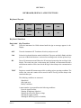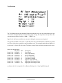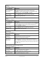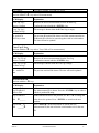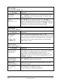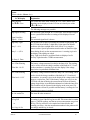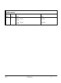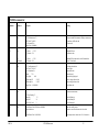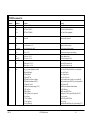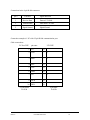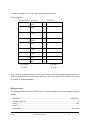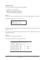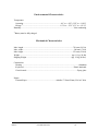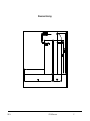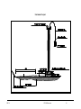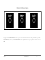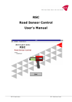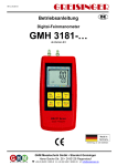
1
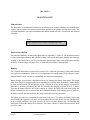
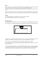
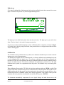
LTL2000 RETROMETER
Manual
On site quality control of road markings & road surfaces in accordance with CEN specifications
DELTA - Hjortekærsvej 99 - DK -Kgs. 2800 Lyngby - Denmark - Tlf (+45) 45 88 83 33 - Fax (+45) 45 87 08 10
DISCLAIMER
The information contained in this document is subject to change
without notice.
DELTA LIGHT & O PTICS MAKES NO WARRANTY
OF ANY KIND WITH REGARD TO THIS MATERIAL,
INCLUDING, BUT NOT LIMITED TO, THE IMPLIED
WARRANTIES OF
MERCHAN-TABILITY AND
FITNESS FOR A PARTICULAR PURPOSE. DELTA
LIGHT & OPTICS SHALL NOT BE LIABLE FOR
ERRORS CONTAINED HEREIN OR FOR INCIDENTAL
OR CONSEQUENTIAL DAMAGES IN CONNECTION
WITH THE FURNISHING, PERFORMANCE OR USE OF
THIS MATERIAL.
Rev. 990311
i
DELTA
LTL2000 Retrometer
INDEX
SECTION 1 ............................................................................................................................... 1
OPERATING INFORMATION...................................................................................................1
LTL2000 Introduction......................................................................................................................................................1
LTL2000 Retrometer features:........................................................................................................................................2
Getting started:.................................................................................................................................................................3
Calibration:........................................................................................................................................................................3
Zero calibration...........................................................................................................................................................3
Traceable......................................................................................................................................................................3
Control Calibration...........................................................................................................................................................4
Transfer of calibration value. .........................................................................................................................................4
Test, warning and errors .................................................................................................................................................4
Communication.................................................................................................................................................................6
Selected commands....................................................................................................................................................6
SECTION 2 ............................................................................................................................... 7
GENERAL INFORMATION.......................................................................................................7
Rl Measurement ...............................................................................................................................................................7
Factory calibration...........................................................................................................................................................8
Optical principle ...............................................................................................................................................................8
Notes on error sources....................................................................................................................................................8
SECTION 3 ............................................................................................................................. 10
KEYBOARD, DISPLAY AND FUNCTIONS ............................................................................. 10
Keyboard Layout...........................................................................................................................................................10
Keyboard functions.......................................................................................................................................................10
Result Printout................................................................................................................................................................12
Rl Printout..................................................................................................................................................................12
Rl Printout with Measurement ID...........................................................................................................................12
Test Printout...................................................................................................................................................................13
Zero Printout...................................................................................................................................................................14
Calibration Printout........................................................................................................................................................14
Functions and Menu system .......................................................................................................................................15
LTL2000 Command set..................................................................................................................................................21
SECTION 4 ............................................................................................................................. 28
MAINTENANCE...................................................................................................................... 28
General care.....................................................................................................................................................................28
Protection window.........................................................................................................................................................28
Battery .............................................................................................................................................................................28
Fuses................................................................................................................................................................................29
Lamp.................................................................................................................................................................................29
Calibration unit ...............................................................................................................................................................29
Light trap.........................................................................................................................................................................30
Calibration.......................................................................................................................................................................30
Printer...............................................................................................................................................................................32
APPENDIX A ......................................................................................................................... 34
COMMUNICATION FACILITIES ........................................................................................... 34
RS-232C specification....................................................................................................................................................34
Data protocol..................................................................................................................................................................36
Command format ............................................................................................................................................................38
APPENDIX B ......................................................................................................................... 39
ii
DELTA
LTL2000 Retrometer
Special Status Printouts. ......................................................................................................... 39
Initial Status....................................................................................................................................................................40
Status after first Zero.....................................................................................................................................................41
Status after Calibration..................................................................................................................................................42
Status after Rl measurement.........................................................................................................................................43
Status after a Test measurement..................................................................................................................................44
APPENDIX C ......................................................................................................................... 45
SPECIFICATION.................................................................................................................... 45
General Characteristics..................................................................................................................................................45
Electrical Characteristics ...............................................................................................................................................45
Environmental Characteristics .....................................................................................................................................46
Mechanical Characteristics ..........................................................................................................................................46
Dimensional drawings...................................................................................................................................................47
Instrument Layout.........................................................................................................................................................48
Calibration Unit Placement Graphics...........................................................................................................................49
iii
DELTA
LTL2000 Retrometer
SECTION 1
OPERATING INFORMATION
LTL2000 Introduction
The LTL2000 Retrometer is a portable field instrument, intended for measuring the retro reflection
properties of road markings in car headlight illumination, the value Rl (coefficient of retro reflected
luminance) is used. Rl is a measure of the lightness of the road marking as seen by drivers of motorised
vehicles in car headlight illumination. The road is illuminated at an angle of 1.24° and the reflected light
is measured at an angle of 2.29°, which corresponds to an observation distance of 30 metres. Thus
relevant for a motorist viewing situation under normal conditions.
Rl is an important factor in the ON-SITE quality control of road markings.
The operation of the Retrometer is very simple and requires a minimum of instruction. An error message
or warning is given in case of unreliable or erroneous measurement.
The LTL2000 measures the retro reflection and calculates Rl according to international agreements.
Results are presented in plain English on a 16*2 character LCD display. The built-in printer and nonvolatile memory provides ON SITE registration of measurements with corresponding date and time.
Serial communication on RS232 port gives extended command, calibration, diagnostics and data dump
facilities.
DELTA
LTL2000 Retrometer
1
The LTL2000 is powered by a rechargeable lead acid battery, giving several hours of measurement
capacity. A mains powered battery charger is supplied as standard.
LTL2000 Retrometer features:
•
Portable self-contained instrument
•
Measurement in full daylight
•
Automatic stray light compensation and error diagnostics
•
Dry and wet surfaces
•
Plane, textured & profiled markings
•
Measurement geometry and illumination corresponding to realistic viewing condition in
night time traffic
•
Direct digital read out
•
Built-in printer
•
Real time clock
•
Automatic data storage in internal non-volatile memory
•
RS232 serial communication for operation, data dump, extended control and
diagnostics
•
Automatic programmable power off function
•
Easy calibration procedure
•
Calibration unit
•
Carrying case
DELTA
LTL2000 Retrometer
2
Getting started:
Turn the LTL2000 on by pressing <ON>
Hold <ON> pressed until LCD shows:
Retrometer
è
Ready
LTL2000 rev. n
Calibrate instrument if necessary, see Calibration
Remove the base frame and place the instrument over the road marking.
Press <RL> button. Measurement will start instantly, duration app. 3 sec.
When finished the measured Rl value, the date/time and status prompt is displayed.
The Rl value, time and status are automatically transferred to the internal data log for later readout to the
serial communication port.
Press the <PRINT> key to print the measurement result.
Calibration:
Zero calibration.
Mount the instrument in the base frame. Make sure that the light trap is absolutely clean and that the
calibration unit is removed.
Press and hold <2'nd> and then press <ZERO>. Follow the shown instructions.
LCD shows the following text:
Zero Reading
è
Enter to start
Zero Reading
è
Please Wait
Zero Ok
Zero: 0.11%
è
Zero Ok
Ready
The instrument is now ready for the next step in the traceable- or control calibration procedure.
Traceable.
Open the hatch and place the reference calibration unit in the middle position as shown on the graphics
on the bottom plate (see Appendix C - figure 24) and close the hatch.
Press <CALIB> and then <ENTER> to start. Follow the shown instruction.
LCD Shows the following text:
Rl Normal Cal.
è
Enter to Start
Rl Normal =146
Enter=OK↑↓ = edit
DELTA
Mount Normal
è
Enter when ready
è
Rl Normal =147
Enter when OK
LTL2000 Retrometer
Calibrating
Please Wait
è
Calib Done
Remove Rl Normal
3
Edit the value until it corresponds with the Normal value and then press <ENTER>. The Calibration
is now completed and the values stored.
Control Calibration.
Use in case of doubt during on site measurement.
Follow the traceable calibration procedure using the red control calibration unit. Use the Rl value from
the control calibration unit label.
Transfer of calibration value.
At regular intervals the traceable calibration value must be transferred from the reference calibration unit
to the control calibration unit.
Mount the reference calibration unit and perform a Traceable Calibration, replace the reference
calibration unit with the control calibration unit and make a normal Rl measurement. Label the Control
Calibration Unit with the value and the date.
Test, warning and errors
Warning and errors are indicated in the last positions in the display:
Status = *
Everything
O.K.
Status = W Warning
Measurement O.K. but warning condition detected.
Status = L
Warning
Measurement O.K. but high stray light detected.
Status = E
Error
Measurement unreliable.
If the status code is different from * (zero value) then press <MENU> and select the Status Display.
Use <é><ê> to see the possible cause of the problem in plain text.
Use <2'nd><TEST> to execute a special test measurement. <TEST> will make a normal Rl measurement and store the result and important parameters in the special Test Log. Use <PRINT> to print the
result and the status information. If any special condition exists the status will be written in plain text.
Miscellaneous
Scrolling:
Use <2'nd> and <é><ê> for fast scrolling.
Power save:
<MENU> until Off time: nn sec. <ENTER> and <é><ê> to adjust. To disable
the Auto Power Off function set the Off time to less than 60 sec. <ENTER> to
accept.
Date/time:
<MENU> until Date and Time. Then <ENTER> to enable edit, use <é><ê>
to edit Year then <ENTER> to switch to minutes and so on.
Reset log:
<MENU> until Free _Log = xx.x%. <ENTER> to reset.
Measurement ID: <ê> to enable editing of the Measurement ID. Use <é><ê> to edit the indicated
position and <ENTER> to switch to next position.
Deleting Data:
DELTA
<é>to enable deletion of Rl data from the top of the Data Log. The previous
measurement result and its ID (if any) will be shown.
LTL2000 Retrometer
4
DELTA
LTL2000 Retrometer
5
Communication
Use a simple terminal or PC with communication software to control the LTL2000. (Windows Hyper
Terminal will do fine.)
Serial communication setup (RS232 interface):
9600 baud, No parity, 8 bit, 1 stop
Xon/Xoff handshake
Selected commands
?<CR>
LR<CR>
LT<CR>
RL<CR>
RT<CR>
SD<CR>
(Help):
LTL2000 will return command set
(Log dump):
Date, time, Rl, status, mode.
(Test log dump):
Date, time, Rl, lamp on/off, idle, load, status, mode.
(Rl measurement): Rl, date, time, status code, system info.
(Test measurement):
Rl, date, time, status code, extended system info.
(Status dump):
Instrument status.
Remember:
§
§
§
§
DELTA
Recharge battery when possibel. Never leave battery discharged for longer
periods of time.
Keep protection window, light trap and calibration unit clean.
LTL2000 is an optical precision instrument, handle with care.
Store in clean and dry environment.
LTL2000 Retrometer
6
SECTION 2
GENERAL INFORMATION
Rl Measurement
LTL2000 Retrometer measures the Rl (coefficient of retro reflected luminance) parameter. The Rl
parameter represents the brightness of the road markings seen by drivers of motor vehicles by headlight
illumination.
In the LTL2000 the illumination angle is 1.24° and the observation angle is 2.29° simulating a drivers
viewing distance of 30 metres at an eye hight of 1.2 metres. The observation area is app. 45 mm. x 200
mm.
Physically the Retrometer is dominated by the 'control' tower. The tower contains the illuminating and
observation system and the control electronics. At the bottom of the tower an optical system, with
mirrors, directs the beams towards the road surface through a dust-protection window. The measuring
area is shielded by an aluminium housing with a rubber skirt and a light trap.
DELTA
LTL2000 Retrometer
7
The LTL2000 is controlled by a microprocessor. The microprocessor executes the measurement
automatically by the push of a button and presents the result on a display. The result is automatically
transferred to an internal non-volatile memory. The result and corresponding time and date can be
printed by the built-in printer. The LTL2000 is operated with a small keyboard located at the top of the
Retrometer. Further, Retrometer control is possible over a serial communication link (RS232). Stored
data can easily be transferred to a host PC for further processing.
Factory calibration
The LTL2000 Retrometer is factory calibrated. This calibration is carried out by using a special
calibration unit and a specially designed base frame. The calibration unit's Rl value is measured in the
laboratory using traceable methods and equipment.
The enclosed calibration unit and base frame can be used for the control and re-calibration of the
Retrometer.
The LTL2000 is powered by a built-in lead acid battery, which under normal operation will keep the
Retrometer operating a normal working day. The battery is recharged by use of an external charger.
Optical principle
The light is generated by a halogen lamp placed at the top of the tower, see Appendix C - figure 23. The
light is focussed on a rectangular field stop and directed toward the illumination aperture at the front of
the lens. Hereafter the beam is collimated by the lens and directed toward the road by a 50% beam
splitter. The observation system is equivalent to the illuminating system. The reflected light enters the
detection system mirror which deflects the light trough the collimator lens and observation aperture to
the detector unit in top of the tower.
Observation field and angle are defined by field stops and apertures. The retro reflected light is collected
by the detection mirror and by the lens focussed on an optical fibre bundle. The light is by the optical
fibre bundle guided to an photo multiplier. An optical filter is placed in front of the photo multiplier to
obtain colour matching.
Notes on error sources
Stray light can enter the instrument between the rubber skirts and the road. Leakage will under normal
measurement conditions not be significant. Nevertheless it may occur. Before each measurement the
LTL2000 automatically evaluates the leakage. The result is compensated before read out. In case of a
significant leakage level a warning or error message is given and special precautions may be necessary.
Instrument leak, drift and offset errors are compensated by means of data obtained during the calibration
procedure. It is very important to keep the light trap, the dust-protection window and the ceramics on
the calibration unit clean. Especially the light trap is critical.
The LTL2000 illumination angle is 1.24° relative to the road surface. Because of this small angle accurate
placement on the road is important. Avoid pebbles and abnormal irregularities. The LTL2000 must be
parallel and close to the road.
DELTA
LTL2000 Retrometer
8
The LTL2000 Retrometer is a rugged instrument, but it is an optical instrument and must be handled as
such.
The LTL2000 is factory calibrated. Nevertheless start important measurements with a calibration before
removal of the base frame. Study the Retrometer status and error messages if any. See also Section 4
- Maintenance
Note
Keep light trap, dust-protection window and ceramics on
calibration unit clean.
Keep battery fully charged. A well charged battery is more
resistant to ageing and damage by freezing.
DELTA
LTL2000 Retrometer
9
SECTION 3
KEYBOARD, DISPLAY AND FUNCTIONS
Keyboard Layout
RL
CALIB.
ENTER
TEST
ZERO
CANCEL
MENU
OFF
ê
ON
PRINT
é
2'nd
FEED
Keyboard functions
Key Label
ON
Key Function
Turns the instrument On. Hold activated until the sign on message appears in the
Display.
OFF
Turns the instrument Off. Terminates all activity and powers off.
2'nd
Selects the keyboard function marked with black. First press and hold <2'nd> and then
press one of the black functions. Activates fast scrolling mode with the up/down keys
RL
Does a Rl measurement and Shows the Rl result and measuring date and time in the
display. The result, date, time, a short status and, if defined, a measurement ID with a
measurement number will be stored in the Rl log for later dump to the communication
port.
TEST
Begins an extended Rl measurement while recording various operating conditions. The
results, date, time and a status will be stored in the Rl Test log for later dump to the
communication port.
The following conditions are measured:
Signal level
Stray light level
Battery conditions
A status number is generated from the following conditions.
Error for signal overflow
Warning for high stray light level
Warning for critical low battery voltage
Warning for signal overflow
Warning for full Rl log (can be disabled)
DELTA
LTL2000 Retrometer
10
Warning for full Test log (can be disabled)
Warning for pour measurement conditions
CALIB
ZERO
Activates calibration measurement. The result is stored in the Test Log.
Activates instrument zeroing measurement. The result is stored in the Test Log
ENTER
Activates selected function, accepts changed settings and confirms choices.
CANCEL Cancels selected function or menu and return to top control level displaying the latest Rl
result.
PRINT
Outputs latest measurement result on printer.
Printout has to finish completely before any other function can be selected, printout
can only be terminated with <OFF>.
FEED
Feeds paper some lines.
MENU
When in normal operation mode the <MENU> Key opens the menu system and
displays the first item in the menu stack. When already in menu mode it selects the next
menu item (<2'nd> <MENU> selects the previous menu item) cancelling any changes
to the current menu function. It is possible to leave the menu mode entirely at any time
and with no changes to the current menu function with the <CANCEL> key or by
selecting one of the other key functions.
é
Deletes the measurement from the top of the Data Log. The Rl value from the previous
Rl measurement will be shown, if a Measurement ID was defined for that measurement
it will be restored as well. If the menu system is selected it functions as a Scroll or
Increment function. Values are incremented until they reach their predefined max. limit
and then automatically change to their predefined min. limit. The key is auto repeating
(press <2'nd> for fast increment).
ê
Edits the Measurement ID. If the menu system is selected it functions as a Scroll
or Decrement function. Values are decremented until they reach their predefined
min. limit and then automatically change to their predefined max. limit. The key is
auto repeating. (Press <2'nd> for fast decrement)
DELTA
LTL2000 Retrometer
11
Result Printout
Rl Printout
The Rl result printout showing the measured Rl, the date and time for the measurement, the instrument
status code and a R# number showing the number of measurements in the Rl log. The Rl result printout
can only follow after a measurement performed with the <Rl> key.
Rl Printout with Measurement ID
If the measurement ID has been set to anything other than 6 white space then the ID is printed along
with a serial number showing the number of measurement done with that ID.
DELTA
LTL2000 Retrometer
12
Test Printout
The Test Printout showing the measured Rl, the date and time for the test, the related status code and
a T# number showing the number of measurements in the Test log. The test printout can only follow after
a measurement performed with the <2'nd> + <TEST> key.
Signal levels and battery conditions are measured during the measurement and printed.
If any special condition exists (status > 0) then the status code is decoded and the conditions are printed
(see below), in the above example no special conditions exist. The measured signal and stray light levels
are shown in % of their full scale values. The battery voltage before and during measurement is shown.
Status code interpretation:
bit pattern
Status Code: 00000001
Status Code: 00000010
Status Code: 00000100
Status Code: 00001000
Status Code: 00010000
Status Code: 00100000
Status Code: 01000000
Status Code: 10000000
value
1
2
4
8
16
32
64
128
Description
Not defined
Stray Light Warning
Rl Log full Warning
Test Log full Warning
Low Battery Warning
High Zero signal Warning
High Signal with Lamp on Error
High Signal with Lamp off Error
eg. Status code 18 is composed of Low Battery Warning (16) + Stray Light Warning (2)
DELTA
LTL2000 Retrometer
13
Zero Printout
The printout after a Zero measurement showing the measured Zero Signal in % of the nominal signal, if
the zero signal is within a specified limit OK is printed, if the zero signal becomes high a warning is
printed. A T# number showing the number of measurements in the Test log and the date and time for
the measurement, The Zero printout can only follow after a measurement performed with the <2'nd>
+ <ZERO> key.
Calibration Printout
The printout after a Calibration measurement showing the selected Rl Normal value. A T# number
showing the number of measurements in the Test log and the date and time for the calibration. The
Calibration printout can only follow after a measurement performed with the <CALIB> key.
DELTA
LTL2000 Retrometer
14
Functions and Menu system
Rl Calibration
(Activate with the <Calib.> key)
LCD Display
Explanation.
Rl Normal Cal.
Enter To Start
Performs instrument calibration.
<ENTER> opens Rl Calibration sub menu.
Mount Normal
Enter When Ready
The user is requested to place his Rl-Normal in the LTL2000
instrument.
Press <ENTER> when it is mounted correctly.
Calibrating
Please wait
Measures Rl on the mounted Rl-Normal.
Rl Normal 146
Enter=OKêé=edit
The display shows the measured Rl value.
Use <ENTER> or <ê ><é > keys
Rl Normal 146
Enter When OK
If necessary use the <ê ><é > keys to change the Rl reading down or
up, continue until the shown Rl normal value is identical to the value
printed on the calibration unit and press <ENTER>.
Calib Done
Remove Rl Normal
The display shows that a new Rl Normal value has been calculated.
The user is requested to remove the Rl normal.
Zero measurement
(Activate with the <2.nd.>+<ZERO> key)
LCD Display
Explanation.
Zero Reading
Enter to Start
Ready for measuring the instrument ZERO signal. Make sure that the
light trap is mounted and empty, close the hatch and then press the
<ENTER> key.
Zero Reading
Please Wait
Measures the zero signal
Zero OK
Zero: 0.11%
Zero measurement done no errors detected. The measured signal level
is shown.
High Zero Warning
Zero: 7.61%
Warning condition detected, the signal is to high. Check that the light
trap is empty and clean. The following measurements will have the W
status set.
Zero OK
Ready
Instrument Zero OK, now ready for calibration.
DELTA
LTL2000 Retrometer
15
Test Log
(Select with the <Menu> key)
LCD Display
Explanation.
Free T_LOG:95.6%
Enter to Clear
The display shows the free space left in the Test log. Press
<ENTER> to enable clearing. In order to avoid accidental erasing
the data in the log, a second <ENTER> is required.
Enter to Confirm
Press <ENTER> again to set the Test Log to 100% free.
Clearing TestLog
Setting Test Log to 100% free.
Rl Log
(Select with the <Menu> key)
LCD Display
Explanation.
Free LOG:89.3%
Enter to Clear
The display shows the free space left in the Rl Log. Press <ENTER>
to enable clearing. In order to avoid accidental erasing the log, a
second <ENTER> is required,
Enter to Confirm
Press <ENTER> again to set the Rl Log to 100% free.
Clearing Rl_Log
Setting Rl Data Log to 100% free.
Print Rl Log
(Select with the <Menu> key)
LCD Display
Explanation.
Print Rl Log
Enter to Select
Output all the data in the Rl Log to the printer.
Data in the Test Log can not be printed.
Log count =nn
Enter to Print
The display shows the number of measurements in the Data Log.
Press <ENTER> to start printing. The Print process continues until all
the data has been printed,(newest first) The only way to stop is with
the <OFF> key.
Enable/Disable Log Full Warning In LCD
(Select with the <Menu> key)
LCD Display
Explanation.
Log Warning Disable
é to Change
The Log Full Warning feature is disabled.
Press é to enable. Press <ENTER> to accept.
Log Warning Enable
The Log Full Warning feature is enabled.
DELTA
LTL2000 Retrometer
16
é to Change
Press é to disable <ENTER> to accept.
Clear Top Log
(Activate with the <é> key after a Rl measurement)
LCD Display
Explanation.
Clear Top Log?
Enter to Confirm
Removes the newest measurement from the Rl Data Log.
Confirm the removal with the <ENTER> key.
Clear Top Log?
No Data in Log!
This message is shown when the Rl Data Log is empty.
Rl:..mcd/m2/lx
(ID-Text) or time
The previous Rl result will be shown and if this measurement has an
ID then this ID will also be restored together with its serial number.
The time will not be updated!
Clear Top T-Log
(Activate with the <é> key after a Test, Calib or Zero measurement)
LCD Display
Explanation.
Clear Top T-Log?
Enter to Confirm
Removes the newest measurement from the Test Log.
Confirms the removal with the <ENTER> key.
Clear Top T-Log?
No Data in Log!
This message is shown when the Test Log is empty.
Rl:....mcd/m2/lx
time
The previous result will be shown. The time will not be updated!
Measurement ID
(Activate with the <ê> key)
LCD Display
Explanation.
Seq ID:ABcd12
Enter to Edit
The Measurement ID is shown. Press the <ENTER> key in order to
edit the 6 position ID string.
Seq ID:ABcd12
Edit é______
An é indicates the active edit position, use <é><ê> to change the
value above the pointer. Press <ENTER> to switch to the next
position.
Seq ID:AB__#1
Edit ______é
Press <ENTER> on the last position to activate the new
Measurement ID, this also resets the serial number to 0 for the new
ID.
DELTA
LTL2000 Retrometer
17
Date and Time
(Activate with the <Menu> key)
LCD Display
Explanation.
Date and time
Enter to Edit
The built-in real time clock can be set by selecting this menu function.
Press <ENTER> to show the present setting. The format is yearmonth-day hour:minute
Edit Year
1997-03-18 13:30
Use <ê><é> keys to change the setting. Press <ENTER> to
switch to edit Month, edit Date, edit Hour and edit Minute. When the
display shows the desired date and time press <ENTER> a last time
to actually set the real time clock to the displayed setting.
Off Function
(Select with the <Menu> key)
LCD Display
Off Time:60 sec
Enter to Edit
or
Off Timer disable
Use éê to Edit
Explanation.
In order to prolong the operational time of the LTL2000
it has an automatic off function that shuts off the power when no action
has been going on for more than a programmable time. The automatic
turn off time can be from 60 to 600 seconds or it can be disabled
entirely (time < 60 sec.).
Default setting
(Select with the <Menu> key)
LCD Display
Explanation.
Set ROM defaults
Enter to Reset
If something goes wrong or appears to be wrong in the programming,
it is possible to reestablish the default settings for various
programmable values. This enables the user to start over from a
default state. In order to avoid accidental reprogramming, a second
<ENTER> is required.
Set ROM defaults
Enter to Confirm
Press <ENTER> again to activate the action.
Setting Default
Values from ROM
Default values are loaded from the permanent memory. The LOG
data is NOT effected.
Rl: 0 mcd/m2/lx
xx:xx:xx
*
The instrument is now ready for new setup.
Xx:xx:xx indicates no valid measurements done.
DELTA
LTL2000 Retrometer
18
Status
(Select with the <Menu> key)
LCD Display
Status Display
Use éê to View
Explanation.
The results and status made with the Rl, Test, Calib. and the Zero
functions can be displayed in the LCD one at a time by use of the
<é><ê> keys.
The following messages are possible.
High Signal Warning
Signal Overflow
Signal = 12.4%
High Stray Light
Stray L = 0%
Stray L = 4,51%
The measured signal strength in % of full scale. If the measured signal
is over a predefined limit then a warning will be displayed for one
second.
The measured signal level is shown
The measured stray light, representing the amount of light getting into
the LTL2000 from outside. A high Stray Light signal can indicate
problems with direct sunlight from a low sun on a very rough or
uneven surface. Special precautions must be taken to hinder the light
from shining directly on the measurement area. A warning is given in
the display if the signal gets critical.
Stray Light levels under a predefined limit are displayed as 0%
No Stay Light data after a ZERO measurement.
No Stray L. Data
Low VBat Warning
VBat idle =10.6V
Low VBat Warning
VBat load =11.2V
The battery voltage measured just before the lamp is lit. The reading
can be used to check the charge condition of the built-in 12 V Lead
Acid accumulator. A warning is given in the display if the voltage
drops below its predefined minimum limit.
The battery voltage measured while the lamp is lit. The reading can be
used to check the charge condition of the built-in 12 V Lead Acid
accumulator. A warning is given in the display if the voltage under load
drops to a critical low value. If the battery voltage gets very low, the
LTL2000 will shut off during the measurement because the battery
voltage drops below its predefined minimum level when the lamp is lit.
This condition will be reported in the display on the next power Up.
Measurements will not be possible until the battery is recharged or an
external power source is applied.
Rl=146 mcd/m2/lx
The latest Rl value measured.
Rl Log Full
A warning is given if the Rl Log has run full. This means that it contains
approx. 1000 Rl readings, and that no new measurements can go into
the log. The log will have to be emptied and cleared before this
warning goes away. Also the measurement number in the printout will
not change until the log is cleared.
or
Free Log: 96.1%
DELTA
LTL2000 Retrometer
19
The amount of free log entries in %.
Test Log Full
or
Free T_Log: 87.5%
A warning is given if the Rl Test Log has run full. This means that it
contains approx. 100 test readings, and that no new Test measurements can go into the log. The log will have to be emptied and cleared
before this warning goes away. Also the Test number in the printout
will not change until the test log is cleared.
The amount of free testlog entries in %.
LTL2000 rev. 2.0
The LTL2000 instrument ID and revision level.
(c)97-03-13
The firmware creation date.
DELTA
LTL2000 Retrometer
20
LTL2000 Command set
The LTL2000 is equipped with a serial communication port primarily for log data acquisition, calibration and test, however all normal LTL2000 functions can be
controlled from this interface.
The following commands have been defined
LTL2000 command set
Command
DA
Parameter
Response
Meaning
none
1997 3 27
1997 Mar 21 09:45:47
1997 Mar 27 16:39:45
Real time clock Date and time
New Date (time unchanged)
DR
none
*** Rl Measurement ***
1994-Mar-27 10:03:56
Rl: 145 (mcd/m2)/lx
Status Code: 0 00000000
Query Latest Rl Measurement
Date and time
Result
Status
DS
none
*** Zero Measurement ***
Lamp On
: 12
Lamp Off
: 10
System Leak
:3
*** Calibration ***
Lamp On
: 163
Lamp Off
: 10
On-(Off+Sys_Leak) : 151
Rl_Factor
: 1.937
*** Rl, RT and Internal Data ***
Lamp Off
: 149
Stray Light
:0
Rl_Result
: 144.6
Quick overview of the latest measurements
Latest zero measurement
Signal with lamp on
Signal with lamp off
System leak signal
Latest Calibration
Signal with lamp on
Signal with lamp off
Calculated signal
Calculated Rl_Factor
Latest Rl, RT measurement
Signal with lamp off
Stray light signal
Rl result
DT
none
*** Rl Test Measurement ***
1997-Mar-27 10:02:30
Rl =144 (mcd/m2)/lx
Signal:
7.3%
Stray Light
0.0%
Latest test result
Date and Time
Measured Rl result
Measured signal
Measured stray light signal
DELTA
LTL2000 Retrometer
21
LTL2000 command set
Command
Parameter
DT cont.
Response
VBat Lamp Off:
VBat Lamp On:
Status code:
Meaning
Battery voltage with min. load
Battery voltage with max. load
Actual Status code
12.21 V
11.30 V
0 00000000
FV
none
II
none
Y
N
Initialise Instrument settings [Y/N]
Initialising Instrument. Zero and Calibrate
II Command Terminated
Set Default values from ROM
Execute initialisation, Instrument not calibrated!
Cancel initialisation command without any change
LC
none
Rl Log empty
Rl log clear message
LE
none
1997-03-27 10:00:59, 146, 0, ,
1997-03-27 10:01:11, 146, 0, ,
1997-03-27 10:01:22, 146, 0, 12345, 1
1997-03-27 10:01:28, 146, 0, 12345, 2
1997-03-27 10:01:45, 146, 0, Test A, 1
1997-03-27 10:01:50, 146, 0, Test A, 2
Data in Rl Log is output comma separated for input to
standard spreadsheet
LR
none
LTL Log Dump: 1997 Mar 27 10:01:53
6 entries 99.56% free
Date
Time
Rl
Status ID #
Y-M-D H:M:S (mcd/m2)/lx
1997-03-27 10:00:59 146
0
1997-03-27 10:01:11 146
0
1997-03-27 10:01:22 146
0 12345 1
1997-03-27 10:01:28 146
0 12345 2
1997-03-27 10:01:45 146
0 Test # 1
1997-03-27 10:01:50 146
0 Test # 2
*
Log dump date and time
Log statistics
Log header
Data units
Rl data without Measurement ID
DELTA
Retrometer
LTL2000 rev.2.0
DELTA L&O
(c)97-03-13
The Firmware ID
Revision number
Copyright message
Creation date
LTL2000 Retrometer
Rl data with Measurement ID
Measurement ID changed
End of log
22
LTL2000 command set
Command
Parameter
Response
Meaning
LS
none
Rl DataLog: 6 data points.
99.56% free
Rl TestLog: 3 data points.
98.80% free
Rl log statistics
DELTA
Test log statistics
LTL2000 Retrometer
23
LTL2000 command set
Command
Parameter
Response
Meaning
LT
none
LTL2000 Test Log Dump: 1997 Mar 27 10:01:03
3 entries 98.80% free
Date
Time
Rl
Lamp
Idle
Load Status Mode
Y:M:D
H:M:S
mcd/m2/lx
On
Off
[v]
[v]
#
[Z,C,T]
1997-03-27
10:00:34
-1
12.0
9.5
12.2 11.3
0
Z
1997-03-27
10:00:45
146
162.9 9.6
12.2 11.3
0
C
1997-03-27
10:01:03
146
162.3 9.6
12.2 11.3
0
T
*
Test log dump date and time
Log statistics
Log header
Data units
Rl zero
Rl calibration
Rl test measurement
LWT
LWF
none
Log Full Warning Display On
Log Full Warning Display Off
Enable the Log Full warning in LCD
Disable the Log Full warning in LCD
LX
none
Rl Test log empty
Rl test log clear message
MC
none
Averring Measurement count 1000
new count
New value for averring
Number of single measurements used to build an average
signal for calculation of Rl
New value
The instrument is now un calibrated !
OT
none
59
180
Automatic off timer = 120 sec.
Automatic off function disable
Automatic off timer = 180 sec.
Automatic turn off time when not in use. Range 60 to 600
sec. Disable for time < 60 sec
RC
none
Y
Calibrate Instrument? [Y/N]
Calibrating Instrument!
**** Calibration ****
Lamp On:
163
Lamp Off:
10
Stray Light:
0
On-(Off+SyLeak):
151
Now use RN n command to set new normal value
Confirm calibration with <Y>
Perform calibration measurement
Signal with lamp on
Signal with lamp off
Stray light signal
Compensated signal
Prompt the user to execute the RN command to enter the
correct Rn Value
DELTA
LTL2000 Retrometer
24
LTL2000 command set
Command
Parameter
Response
Meaning
RL
none
*** Rl Measurement ***
1997 Mar 27 10:00:59
Rl: 146 (mcd/m2)/lx
Status Code: 0 00000000
Performs a normal Rl measurement. Displays measurement
date and time, the Rl result and
the Status code
RN
none
Rl_Factor
= 2.312
Rl_Normal = 138
Calculated Rl factor
Rl calibration value
150
(Rl Normal)
Rl_Factor
= 2.151
Rl_Normal = 120
Calculated Rl factor based on the new Rl normal value
entered 150 mcd/m2/lx
RT
none
*** Test Measurement ***
1997-Mar-27 10:01:03
Rl =146 (mcd/m2)/lx
Signal:
7.3%
Stray Light:
0.0%
VBat Lamp Off:
12.18 V
VBat Lamp On:
11.28 V
Status Code: 0 00000000
Test header date and time
Date and Time
Measured Rl result
Measured signal
Measured stray light signal
Battery voltage with min. load
Battery voltage with max. load
Actual Status code
RZ
none
*
*** Zero Reading ***
Lamp On:
12
Lamp Off:
10
New Rl_Sy_Leak:
2
Perform zero measurement
Actual Status Code: 0 Bit Pattern: 00000000
Status breakdown:
Status code and bit pattern
if status not zero then the status code is decoded
Actual Status Code: 16 00010000
This example shows a status value of 16. It decodes to
SD
DELTA
none
Signal with lamp on
Signal with lamp off
New SyLeak signal
LTL2000 Retrometer
25
LTL2000 command set
Command
Parameter
Response
Warning: Low VBat
Meaning
Warning for low battery voltage
TI
none
10.0.0
1997 Mar 27 16:45:51
1997 Mar 27 10:00:00
Real time clock Date and Time
New Time (Date unchanged)
TO
none
Sensor Off
Turn sensor off (power off)
VA
none
new setpoint
Low VBat alarm: 11.0 V
Low VBat alarm: new value V
Setpoint for low bat warning
New set point for low bat warning
VB
none
VBat =12.21 V
Measure actual voltage on lead-acid battery
VF
none
wanted [V]
Volt Factor = 0.0153
Volt Factor = 0.0146
Voltage calibration factor
New wanted reading (in Volt!)
VS
none
VBat Lamp off: 12.21V
VBat Lamp on : 11.30V
Measured VBat with min. load
Measured VBat with max. load
<?>
none
Date [yyyy mm dd] display/set Date
DR Dump Rl Signal
DS Dump Signal
DT Dump Rl Test
DPP Dump Extra Status to Printer
DPS Dump Extra Status to RS232
FV Firmware Version
II Initialise Instrument settings [Y/N]
LC Rl Log Clear
LR Rl Log Dump
LE Rl Log Dump <tab> separated
LS Log Status
LT Test Log Dump
LX Test Log Reset
LWn Log Warning
Query/Set Real Time Watch Date year/month/date
Query last Rl result
Query Signal Status
Query last Test result
Dump extended status to printer (see appendix B)
Dump extended status to RS232 port (se appendix B)
Query Firmware ID
Enable/Execute Instrument Initialisation
Clear RL Data log
Send RL log to RS232 Port
Send Special <TAB> separated RL log to RS232
Query log status
Send Test log to RS232 Port
Clear Test log
Enable/Disable the Display of Log full warning [T/F]
DELTA
LTL2000 Retrometer
26
LTL2000 command set
Command
<?>
<?> cont.
DELTA
Parameter
None
Response
Meaning
MC Average Measuring Count
OT n Auto Off Timer
Query/Set the Averring Count for noise reduction
Query/Set the Automatic Turn Off Timer
PV PMT Voltage
PF PMT Volt factor
RC Calibration Measurement
RL Rl Measurement
RN n Normal Measurement
RT Test Measurement
RZ Zero Measurement
SD Status Dump
SN Measurement ID
TI Time [hh:mm:ss] Display/Set time
TO Turn Sensor Off
VA Volt Alarm for Low Bat
VB VBat
VF Volt factor
VS Return Volt-Idle, Volt-Load
Query PMT voltage
Calibrate V-PMT
Execute Calibration measurement
Execute RL measurement
Query/Set Rl Normal value
Execute Test measurement
Execute Instrument Zero measurement
Query instrument status
Query/Set Measurement ID
Query/Set Real Time
Turn LTL2000 off
Query/Set Alarm for low Battery voltage
Query Battery Voltage
Calibrate Voltage reading
Query V-Bat for Idle and Load conditions
LTL2000 Retrometer
27
SECTION 4
MAINTENANCE
General care
The Retrometer is constructed for outdoor use in ordinary good weather conditions. It will stand moist
weather with wet roads, but caution must be taken against rain or splashes and dirt from traffic. The
LTL2000 Retrometer is an optical instrument and shall be handled as such. Avoid shock and vibration
if possible.
Note
Keep dust/protection window and light trap clean
Protection window
The protection window is located in the optical unit, see Appendix C - figure 23. The protection window
is coated with a high efficiency anti reflection coating. Care must be taken not to damage this coating by
cleaning. A fine brush can be used for removing loose particles/dust. If this is not sufficient the window
should by cleaned using a soft paper tissue or cloth and some window cleaning liquid.
Battery
The LTL2000 Retrometer is powered by a sealed 12V/3.5Ah lead acid battery, which under normal
use requires no maintenance. However it is recommended to keep the battery fully charged. A fully
charged battery is more capable of withstanding low temperature and ageing.
Battery charger is provided as a standard accessory for charging the battery from mains. The output
cable of the charger is equipped with a socket matching the connector in the instrument. Connect charger
to mains and instrument. The red indicator will be switched on as long as the charging is in progress.
Thereafter it switches periodically on and off. Normally the charging will take about 8-12 hours.
Typically the battery achieves 90% of the capacity in 5 hours. No harm will result from leaving the
charger connected for time in excess of the above indicated duration of the charging process. However,
the battery must be disconnected from the charger when disconnecting the mains.
The battery is located in a compartment at the front of the tower. To replace the battery remove the
screws holding the right side cover plate, seen from behind. Remove the screws from the right hand side
of the red front- and back cover plate. Remove the side cover plate. Remove the 2 nuts holding the
clamp plate. Lift out the battery of its container. The battery can now be removed and renewed. Refit
in reverse order.
DELTA
LTL2000 Retrometer
28
Fuses
Fuses, two pieces, are placed at the rear of the instrument. The charging fuse protects the battery against
short circuit and other errors in the charging connector, charger or charging system.
The battery fuse protects battery and electronics against short circuit and other errors in the electronic
system.
Always renew a blown fuse with one of equal rating. To change a fuse carefully unscrew the plastic cap
fuse holder by using eg a coin. Pull out the fuse from the cap and insert the new one and reassemble
Lamp
The halogen lamp requires no maintenance. At life end it must be renewed.
It is recommended that renewing is done by trained personal.
Calibration unit
The road marking is simulated by a piece of white ceramics mounted on a aluminium block with a small
grip. Ceramics has very stable optical properties and cleaning is easy because of the smooth surface.
To make sure that calibration of the Retrometer is correct it is important that the ceramics on the
calibration unit is clean and undamaged. All ways keep the calibration unit well protected.
If the ceramics is stained, scratched or broken the calibration unit has to be renewed.
In case of dust on the ceramics surface, clean gently with a damp soft cloth if necessary use a mild
household detergent.
To ensure reliable measurements, it is recommended that the calibration unit is periodically recalibrated
to a traceable standard. DELTA Light & Optics offers calibration traceable to PTB (PhysikalsichTechnishe Bundesanstalt). For information contact your distributor or DELTA Light & Optics.
DELTA
LTL2000 Retrometer
29
Light trap
Zero signal is simulated by a light trap made of two glossy and black plastic sheets mounted in an acute
angle. If clean this will provide very efficient light absorbing device.
The light trap is the tilted black plastic sheet and the area below. The light trap is a part of the base
frame. The base frame is also used for transport protection.
It is necessary to disassemble the light trap to clean it efficiently. This is easily done as shown in Figure
9. Cleaning can be done by using a fine brush, clean pressurised air or a soft paper tissue/cloth and some
window cleaning liquid.
Calibration
The LTL2000 is factory calibrated and very stable; but a calibration should always be carried out before
starting a new series of measurements.
The instrument is supplied with two calibration units. A reference calibration unit (aluminium base) and
a work calibration unit (red plastic base). The reference calibration unit is factory calibrated and
traceable to PTB. The work calibration unit must be calibrated against the reference calibration unit by
the user at suitable intervals. The reference calibration unit is stored in a protective box. The work
calibration unit is placed in a compartment below the printer. This facilitates easy access during field
operation.
When calibrating, first mount the LTL2000 in its base frame and then perform a <ZERO> reading Then
open the hatch in the instrument and place the calibration unit on the black plastic sheets right over the
middle marking and with the ceramics surface pointing in the shown direction towards the tower, close
the hatch and perform a <CALIB.> reading. Now edit the suggested RL value with the edit keys so that
it matches the value printed on the calibration unit and Rl and then press <ENTER>.
The instrument automatically compensates for zero signal, leakage and other known errors, and
DELTA
LTL2000 Retrometer
30
calculates the calibration factor. This process is fully automatic and if the calibration routine is followed
precisely the Retrometer will now display 'True' Rl.
Always store the reference calibration unit in a dry and clean environment. At regular intervals the
traceable calibration value must be transferred from the reference calibration unit to the control
calibration unit.
See also section 1: Calibration and section 3: Functions and Menu system and Command set.
DELTA
LTL2000 Retrometer
31
Printer
The printer is a high speed high quality Mini Thermal Printer. It uses 57.5 mm thermal paper (type
KF50). It has only a few moving parts and does not require any special or periodic maintenance.
Replacing the paper is easily done by first pushing the spring loaded transparent cover downwards to
disengage it from the upper black part, let it swing down and insert a new paper roll. A handwheel
makes it easy to insert the paper. Close the cover in reverse order.
DELTA
LTL2000 Retrometer
32
DELTA
LTL2000 Retrometer
33
APPENDIX A
COMMUNICATION FACILITIES
RS-232C specification
The LTL2000 is equipped with a communication facility that enables the use of a simple data terminal
or an ordinary PC type computer for control of LTL2000 functions and for log data acquisition.
The computer or terminal connects to the LTL2000 using a communication cable fitted with a 9 pin male
D-Sub connector at one end and a 9 or 25 pin connector at the other end.
The electrical connections meet the EIA/TIA-232E and CCITT V.28 specifications. e.g. it can be
connected to any standard RS232 serial communications port with the below wiring.
DELTA
LTL2000 Retrometer
34
Connections in the 9 pin D-Sub connector.
pin #
Function
Signal Direction
3
Receive Data
Data to LTL2000
2
Transmit Data
Data from LTL2000
5
Signal Ground
Signal Ground
Connection example #1. PC with 25-pin D-Sub communication port.
Cable connections:
PC Port DTE
pin name
LTL DTE
1
FG
X
2
TxD
--
3
3
RxD
--
2
4
RTS
X
5
CTS
X
6
DSR
X
7
SG
--
8
DCD
X
20
DTR
X
25-pin female
D-SUB
DELTA
5
9-pin male
D-SUB
LTL2000 Retrometer
35
Connection example #2. PC with 9 pin D-Sub communication port.
Cable connections:
PC Port DTE
pin name
LTL DTE
1
CD
X
2
RxD
--
2
3
TxD
--
3
4
DTR
X
5
SG
--
6
DSR
X
7
RTS
X
8
CTS
X
9
RI
X
9-pin female
D-SUB
5
9-pin male
D-SUB
As it can be seen, the interconnections have been held to an absolute minimum, and in some rare
situations there will have to be established additional connections on the PC side. Please refer to your
PC manual for further information.
Data protocol
The communication between the LTL2000 and the computer equipment takes place using the following
settings:
Baud Rate ..............................................................................................................9600 bit/sec.
Number of data bit .................................................................................................................. 8
Parity ................................................................................................................................ none
Stop bit ...................................................................................................................................1
Hand Shake ............................................................................................................. XOn/XOff
DELTA
LTL2000 Retrometer
36
DELTA
LTL2000 Retrometer
37
Command format
All LTL2000 commands are built using the following template.
Command (one ore more letters)
Delimiter(one ore more spaces, optional)
Parameter (Integer or Real number, optional)
Command End (Carriage Return, mandatory)
Example #1:
The user wants to see how the Automatic Off timer is set and then change the value to 120 seconds.
The command and the response sequence look like this.
Ot
Automatic Off Timer = 300 sec.
Ot 120
Automatic Off Timer = 120 sec.
If for some reason the communication fails or the command is undefined the LTL2000 responds with
a question mark. <?>
If the parameter lies outside the defined range for that parameter, the LTL2000 returns the present
setting without any change.
Example #2:
The user wants to read the data in the Data Log
The command and the response sequence can look like this.
DELTA
LTL2000 Retrometer
38
APPENDIX B
Special Status Printouts.
The LTL2000 can print a special status at power up showing all internal settings and values generated
by the different functions.
The status printout is activated by holding the keys <2'nd> and <PRINT> activated during power up.
Once the print process has started release all keys and wait for the completion. The print process can
only be turned off with the <OFF> key.
The following sequence of measurements and printouts was done to show the kind of information the
user can get under different conditions. First the instrument was reset with the II function and the data
and the test log was cleared. Then a Zero measurement was done followed by a calibration, and a
normal Rl measurement was taken, and finally a test measurement was executed. The instrument status
was printed after each step using the described procedure.
The purpose of this Special Status Printout is to give the user an easy way to communicate the instrument
status to a technician in case of problems.
A similar Status can be generated with the DPP command.
DELTA
LTL2000 Retrometer
39
Initial Status
After executing a ZERO function the status will look
like this.
It shows that no Zero measurement has been
executed and also no Calibration.
The values for the highvoltage (VPMT) and battery
voltage are set to their default values.
The Data log status is shown.
The special status shows the setting for the MODE
Switch, the measurement counts for noise reduction,
the automatic off timer, the actual voltage on the
battery, the date and time and finally the firmware
revision # and creation data.
Finally is shown the e-mail address and the WWW
address to DELTA.
Note that the Real Time Clock and the Data
Logs normally will not be affected by a Set
ROM Defaults or a II command.
DELTA
LTL2000 Retrometer
40
Status after first Zero
After executing a ZERO function the status will look
like this.
It shows that the Zero measurement has been
executed and when this was done.
No calibration has been done yet.
The values recorded during the zero measurement,
the system leak, the dark signal and the offset signal
are listed.
The voltage conditions during the zero measurement
are shown:
Battery voltage measured when the lamp is on, the
voltage with the lamp off and finally the PMT voltage:
It can be seen that the data from the zero measurement went into the Test Log.
DELTA
LTL2000 Retrometer
41
Status after Calibration
After executing a Calibration function the status will
look like this.
Data from the Calibration measurement is added to
the list.
Also the calculated Rl Factor is added to the list.
It can be seen that the data from the calibration
measurement went into the Test Log.
DELTA
LTL2000 Retrometer
42
Status after Rl measurement
After executing a Normal Rl Measurement the status
will look like this.
Data from the Rl measurement is added to the list.
It can be seen that the data from the Rl measurement
went into the Data Log.
DELTA
LTL2000 Retrometer
43
Status after a Test measurement
After executing a Test Measurement the status will
look like this.
The values from the Test measurement are added to
the list.
It can be seen that the data from the Test measurement went into the Test Log.
DELTA
LTL2000 Retrometer
44
APPENDIX C
SPECIFICATION
General Characteristics
Illumination angle ............................................................................................................... 1.24º
Observation angle.............................................................................................................. 2.29º
Equivalent observer distance...............................................................................................30 m
Observation angular spread ............................................................................................. ±0.17º
Type 30m CEN
Illumination angular spread horisontal.............................................................................. 0.33º
Illumination angular spread vertical.................................................................................. 0.17º
Type 30m ASTM
Illumination angular spread horisontal.............................................................................. 0.10º
Illumination angular spread vertical.................................................................................. 0.10º
Field of measurement:
Width.............................................................................................................. 45 mm (1.8 in)
Length (typ.) .................................................................................................. 200 mm (7.9 in)
Min. reading (mcd/m2/lx)...........................................................................................................0
Max. reading (mcd/m2/lx)............................................................................................Typ. 2000
Electrical Characteristics
EMC......................................................................................................................EN 50081-1
EN 50082-1
Power supply:
Battery......................................................................... Build in 12 volt 3.5Ah sealed lead acid
External charger............................................................230 VAC charging time app. 10 hours
90% capacity after app. 5 hours
Charger fuse (5*20 mm) .............................................................................................T3.15A
Power supply fuse (5*20 mm).....................................................................................T3.15A
Data memory............................................................................................ >1000 measurements
Data retention (from purchase).................................................................................Typ. 5 years
Serial communication mode.......................................................................................9600,N,8,1
Data flow control......................................................................................................... Xon/Xoff
Interface.......................................................................................................... Modified RS 232
DELTA
LTL2000 Retrometer
45
Environmental Characteristics
Temperature:
Operating.............................................................................0ºC to + 45ºC (32ºF to +114º F)
Storage *) ........................................................................... -15ºC to + 55ºC (5º F to +131º F)
Humidity............................................................................................................ Non condensing
*)
Battery must be fully charged
Mechanical Characteristics
Max. length..................................................................................................... 720 mm (28.3 in)
Max. width........................................................................................................ 200 mm (7.9 in)
Max. height ..................................................................................................... 570 mm (22.4 in)
Weight ......................................................................................................... app. 11 kg (24 lbs)
Shipping Weight .......................................................................................... app. 22 kg (49 lbs.)
Construction:
Housing ..................................................................................................................Aluminum
Keyboard ......................................................................................................Plastic laminated
Circuit boards .......................................................................................................Epoxy glass
Printer:
Thermal Paper .......................................................... with/dia. 57.5mm/35mm (2.26 in/1.38in)
DELTA
LTL2000 Retrometer
46
Dimensional drawings
DELTA
LTL2000 Retrometer
47
Instrument Layout.
DELTA
LTL2000 Retrometer
48
Calibration Unit Placement Graphics.
The graphics show the Calibration Position this is the correct position and orientation for the calibration unit to obtain optimal calibration precision. The
Rear Test Position (near the tower) and the Front Test Position is used to verify that the instrument operates as specified over the entire measurement
area.
DELTA
LTL2000 Retrometer
49