1
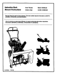
Owner's
Manual
FOUR
WHE
STEER
LAWN
tRACTORS
Thank
you for purchasing
Ill
*
" O
an American-built
IIII
product.
II
MBLY
ON
* MAINTENANCE
IMPORTANT:
Read Safety Rules and
Instructions Carefully
Model Numbers
131754F
131784G
WARNING: This unit is equipped with an internal combustion engine and should not be used on or near any unimproved
forest-covered, brush-covered or grass-covered land unless the engine's exhaust system is equipped with a spark arrester
meeting applicable local or state taws (if any). If a spark arrester is used, it should be maintained in effective working order
by the operator.
in the State of California the above is required by law (Section 4442 of the California Public Resources Code). Other states
may have similar laws. Federal laws apply on federal lands. A spark arrester for the muffler is available through your nearest
engine authorized service dealer.
PRINTED IN U.S.A.
FORM NO. 770-7545F
IMPORTANT
'_THIS
RULESFORSAFEOPERATION
THISSYMBOL
POINTS
OUTIMPORTANT
SAFETY
INSTRUCTIONS
WHICH,tFNOTFOLLOWED,
COULD
ENDANGER
THEPERSONAL
SAFETY
AND/ORPROPERTY
OFYOURSELF
ANDOTHERS.READANDFOLLOW
ALLINSTRUCTIONS
IN THISMANUALBEFORE
ATTEMPTING
TOOPERATE
YOURUNIT.FAILURE
TOCOMPLYWITHTHESEINSTRUCTIONS
MAYRESULT
IN PERSONAL
INJURY.WHENYOUSEE
HEEDITS WARNING.
SYMBOL--&
DANGER:
Yourunitwas builtto be operatedaccordingto the rulesfor safeoperationin thismanual.Aswithany
typeof powerequipment,carelessness
or erroron the partof the operatorcan resultin seriousinjury.
If youviolateany of theserules,you maycauseseriousinjuryto yourselfor others.
1. READTHISOWNER'S
MANUALcarefufly
in itsentiretybeforeattempting
to assemble
or operatethisunit.Keepthis manualin
a safeplace for future and regularreference
and for ordering
replacement
parts.
2. Thisunitisa precisionpieceofpowerequipment,
nota plaything.
Therefore
exerciseextremecautionat all times.
3. Knowthe controls
and howto stopthemachinequickly.
4. Donotallowchildren
under14yearsoldtooperate
vehicle.
Children
14 yearsand overshouldonlyoperateunitundercloseparental
supervision.
Donot allowanyone
tooperateit withoutproperinstruction.
Onlypersonswellacquainted
withtheserulesof safe
operation
shouldbe allowedto use yourmower.
5. Wearsturdy,rough-soled
workshoesandclose-fitting
slacks
and
shirts.Do notwearloosefitting clothesor jewelry.Theycanbe
caught
in movingparts.Neveroperate
a unitinbarefeet,sandals,
or sneakers.
6. To preventinjury,do notcarrypassengersor giverides.Keep
children,petsandbystandersoutof theareawhilemowing.
Only
theoperatorshouldrideon theunitand only ridein the seat.
7. Checkoverheadclearance
carefullybeforedrivingunderpower
lines,guywires,bridges
or low hangingtreebranches,
before
entering
or leavingbuildings,
or in anyothersituation
wherethe
operator
maybestruckorpulledfromtheunit,whichcouldresult
in seriousinjury.
8. Tomaintain
control
oftheunitandreduce
thepossibility
ofupset
orcollision,
operatethetractorsmoothly.
Avoiderraticoperation
andexcessive
speed.
9. Thoroughly
inspecttheareato be mowed.Removeall stones,
sticks,wire,bonesandotherforeignobjects.Keeptheareaof
operation
clearofall persons,particularly
smallchildren
andpets.
Stopenginewhentheyareinthevicinity
ofyourmower.
Although
theareaof operation
shouldbecompletely
cleared
offoreignobjects,a smallobjectmayhavebeenoverlooked
andcouldbeaccidentty
thrownbythe mowerin anydirection
andcauseinjury
toyouora bystander.
Planyourmowingpattern
to avoid
discharge
ofmaterial
towardroads,sidewalks,
bystanders,
petsandthelike.
10. Always
wearsafetyolassesoreyeshieids
duringoperation
or white
performingan adjustment
or repair,to protecteyesfromforeign
objectsthatmay bethrownfromthe machine
in anydirection.
11. Stoptheblade(s)whencrossing
graveldrives,walksor roads.
12. Disengage
allattachmentclutches,
thoroughly
depress
thebrake
pedal,andshiftintoneutralbeforeattempting
to startengine.
13. Beforeleavingtheoperator's
position,disengage
blade(s),place
shiftleverin neutral,engageparkingbrake,shutengineoff and
removekey.
14. Donotput handsorfeet nearor underrotatingparts.Keepclear
ofthedischarge
opening
at alltimesastherotatingblade(s)can
causeinjury.
15. Disengage
powerto attachment(s)
andstopenginebeforemakinganyrepairsor adjustments.
Disconnect
the sparkplug wire
andkeepthewireawayfromtheplugtoprevent
accidental
starting.
16. Beforeattempting
to unclog
themoweror discharge
chute,stop
theengine.
Themowerblade(s)
maycontinue
torotatefor a few
seconds
aftertheengineisshutoff.Therefore,
besuretheblade(s)
havestopped
completely.
Disconnect
thesparkplugwireandkeep
thewire awayfrom theplug to preventaccidental
starting.
17. Disengage
powertoattachment(s)
whentransporting
ornotinuse.
2
!8. Foryoursafety,usetheslope
gaugeincluded
aspartofthismanual
to measureslopesbeforeoperatingthis unit ona slopedor hilly
area.if theslopeisgreaterthan15oasshownontheslopegauge,
do notoperatethis uniton thatareaor seriousinjurycouldresult.
19. Donot stopor startsuddenlywhengoinguphillor downhill.Mow
up and downface of steepslopes;neveracrossthe face. Use
extremecautionifit isnecessaryto drivethetractorupan incline
or backthetractordownan inclinebecausethefront of thetractor couldlift and rapidlyflip overbackwardwhichcould cause
seriousinjury.
20. Reducespeedon slopesandin sharpturnsto prevent
tippingor
loss of control.Alwayskeepthe tractorin low gearwhengoing
downsteephillsto takeadvantage
of engine
braking
action.Choose
a low enoughgearso thatyouwill nothaveto stopor shiftwhile
on the slope.
21. Stayalertfor holesin terrainandotherhiddenhazardswhichmay
causethe unit to tip over.
22. Use carewhenpullingloadsor usingheavyequipment.
A. Useonly approveddrawbarhitch points.
B. Limit loadsto those you cansafelycontrol.
C. Do not turn sharply.Usecare whenbacking.
D. Use counterweight(s)
or wheelweightswhensuggestedin
owner'smanual.
23. Watchout for traffic whencrossing
or near roadways.
24. Whenusinganyattachments,
neverdirectdischarge
of material
towardbystanders
norallowanyone
nearvehicle
whileinoperation.
25. Handlegasoline
withcare.It is highlyflammable.
A. Extinguish
cigarettes,
cigars,pipesandall othersources
of
ignition.
B. Useapproved
gasoline
container.
C. Neverremovecapor addgasoline
toa runningor hotengine
or fill fueltankindoors.
Allowtocoolat least2 minutes
before
refilling.Wipeup spilledgasoline.Alwaysuseoriginaltype
ventedcap.
D. Opendoorsif engineis runin garage.Exhaustfumes are
dangerous.
Do notrunengineindoors.
26. Neverstorethemachine
withfuelinthefueltankinsidea building
wherefumesmayreachan openflameorspark,suchashotwater
andspaceheaters,
clothesdryers,andthelike.Allowtheengine
to coolbeforestoringin anyenclosure.
27. Toreduce
fire hazard,keepengineandcuttingdeckfreeofgrass,
leavesor excessive
greaseor oil.
28. Keepthe vehicleand attachments
in goodoperating
condition,
and keepsafetydevicesin place. Useguardsas instructed
in
operator's
manual.
Donotoperate
thisunitunless
thechutedeflector, guards,andsafetyinterlocksystemareinstalledandfunctioningproperly.
29. Keepall nuts,bolts, andscrewstightto besurethe equipment
is in safeworkingcondition.
30. Thevehicle
andattachments
should
bestopped
andinspected
for
damageafterstrikinga foreignobject.The damageshouldbe
repairedbeforerestarting
andoperating
theequipment.
31. Do notchangetheenginegovernorsettingsor overspeed
the
engine.
RULESFORSAFEOPERATION(CONTINUED)
32. Whenusingthe vehiclewithmower,proceedas follows:
A. Mow only in daylightor in good artificiallight.
B. Nevermakea cuttingheightadjustment
whileengine
isrunning
if operatormustdismountto do so.
B. Shutthe engineoff an_wa'_tunti_t_tebb_e comesto a completestop beforeremovingthe grasscatcher.
D. Checkblademountingbolts for propertightnessat frequent
intervals.Also, checkbladesfor wearor damage(e.g. bent,
cracked).Replacewith bladewhichmeetsoriginalequipment
specifications.
33. Checkgrasscatcherbagsfrequentlyforwearor deterioration.
For
safetyprotection,replaceonlywithnewbagmeetingoriginalequipment specifications.
gL
iii
III
34. Look behindto makesurethe areais ciearbeforeplacingthe
transmissionin reverseand continue
lookingbehindwhilebacking up.Disengage
bladesbeforeshiftingintoreverseandbacking
up.
35. "fhisun'_tshou)dnotbedrivenup a ramponto a traileror truck
underpower,becausetheunitcouldtip over,causing
seriouspersonalinjury. Theunitmustbe pushed
manuallyto loadproperly.
36. Checkbrakeoperationfrequently.Adjustand serviceaccording
to brakeadjustmentinstructionsin this manual.
37. Muffler,engine,andbeltguardsbecomehotduringoperationand
can causea burn. AUowto cooldown beforetouching.
ii
ASSEMBLY
This owner's manual covers two models of lawn
tractors. Follow only those instructions which pertain to your model lawn tractor.
NOTE: Reference to right or left hand side of the
unit is observed from the driver's seat, facing
forward.
Refer to the separate deck manual for all information concerning the deck.
UNPACKING
IMPORTANT:
This unit is shipped WITHOUT
GASOLINE or OIL; however, a small amount of oit
may be present from the factory. Do not overfill.
After assembly, service engine with gasoline and
oil as instructed in the separate engine manual
packed with your unit.
1. Remove the lawn tractor from the carton as follows.
Open the top flaps. The loose parts (includes the
battery fluid, steering wheel with steering cap attached and chute deflector) may be on the seat and
wrapped in plastic, or may be located in a box.
Remove all loose parts and carton inserts. Cut the
front corners of the carton. Make certain brake is
released, use the relief valve and push the unit out
of the carton.
2. The seat has been mounted backward for shipping
purposes. If the loose parts are on the seat, careful_y cut and remo'_e _he plastic "wTap.
ig Screws
NOTE: On some units, the seat may be packed with
the loose parts. The self-tapping screws will be attached
to the seat. Remove the screws and assemble as instructed.
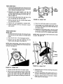
ASSEMBLING THE SEAT
Remove the hex self-tapping screws which secure the
seat to the seat pivot bracket. Turn the seat around and
place in position against the seat pivot bracket_ lining
up the slotted holes in the pivot bracket with the holes
in the seat. Select desired position for the seat, and
secure with hex self-tapping screws. See figure 1.
FIGURE 1.
BATTERY INFORMATION
_WARNING
A. Battery acid must be handled with great care as
contact with it can burn and blister the skin. It is also
advisable to wear protective clothing (goggles, rubber gloves and apron) when working with it.*
B. Should battery acid accidentally splatter into the
eyes or onto the face, rinse the affected area immediately with clean cold water. If there is any
further discomfort, seek prompt medical attention.
C. If acid spills on clothing, first dilute it with clean
water, then neutralize with a solution of ammonia/
water or baking soda/water.
D. Since battery acid is corrosive, do not pour it into
any sink or drain. Before discarding empty electrolyte containers, rinse them with a neutralizing
solution.
E. NEVER connect or disconnect charger clips to battery while charger is turned on as it can cause
sparks.
F. Keep all lighted materials (cigarettes, matches,
lighters) away from the battery as the hydrogen gas
generated during charging can be combustible.
G. As a further precaution, only charge the battery in
a well-ventilated area.
*Always shield eyes, protect skin and clothing
when working near batteries.
Battery
Cover
Battery
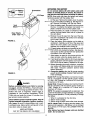
ACTIVATING THE BATTERY
Screwdriver
i ;/
Do not activate battery (fill with battery acid) until
battery is actually placed in service. Be certain to
read previous warnings before activating the battery.
NOTE: Some units may have the battery and battery
hardware packed with the battery fluid.
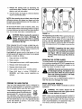
1. Lift the seat. Remove the battery cover by pressing in on the sides and lifting up. See figure 2 inset. Remove the battery from the rear frame.
2. Open the battery pack. Be careful not to puncture
the box. It contains the battery fluid (acid) in a
plastic container and one short plastic tube.
3. Place the battery on a table or workbench. Make
certain the long plastic drain tube is in place on
the vent elbow.
Caps
:
Vent
Clear Plastic
Drain
//
4. Remove the six fill caps from the top of the battery with a screwdriver. Be careful not to damage
the fill caps. See figure 2.
5. Place the battery fluid container on the table or
workbench. Carefully cut off tip of the spout and
attach the short plastic tube provided. Do not
squeeze the container when cutting tip.
6. Fill each battery cell slowly and carefully to the UP"_---PER
LEVEL line marked on battery. See figure 3.
Use caution as the acid level will rise rapidly after
the bottom of the cell is filled.
FIGURE 2.
7. Allow battery to stand for 30 minutes with the fill
caps removed, while the plates absorb acid.
8. If acid level has fallen after the 30 minute standing
period, refill each cell with battery acid to the UPPER LEVEL line on battery. Replace the fill caps.
9. Before discarding the empty container, neutralize
any residue with baking soda and rinse container
with water. Puncture container several times
before discarding.
10. Charge the battery after the 30 minute standing
period. SLOW CHARGE THE BATTERY (DO NOT
FAST CHARGE).
FIGURE 3.
Model 754F: Charge the battery at a maximum bench
rate of 1.4 amperes until the specific gravity reading
is 1.260-1.280. Charge for a minimum of 2 hours and
a maximum of 8 hours.
DANGER
Model 784G: Charge the battery at a maximum bench
rate of 2 amperes until the specific gravity reading is
1.265. Charge for a minimum of 3 hours and a
maximum of 5 hours.
Battery contains sulfuric acid. Refer to warning
on page 3. Antidote: EXTERNAL--Flush with water.
INTERNAL--Drink large quantities of water or milk.
Follow with milk of magnesia, beaten eggs or
vegetable oil. Call physician immediately. EYES:
Flush with cool water for at least 15 minutes, then
get prompt medical attention.
NOTE: This engine is equipped with an alternator. The
current for the battery charger alternator is unregulated.
During normal operation, it is only necessary to charge
the battery:
1. When it is activated for the first time.
2. Before winter storage.
3. Before using the lawn tractor after winter storage.
NOTEIModel
754F: Charging rate after battery has
been put into operation--the
battery is to be charged
for a period of 14-16 hours. NO LONGER THAN 30
HOURS.
After battery has been charged, add only distilled
water. Do not add acid.
Since batteries produce explosive gases, keep all
lighted materials (cigarettes, lighters, matches,
etc.) away. Be sure to charge battery only in wellventilated areas. Make certain venting path of battery (drain tube) is always open.
KEEP BATTERIES
OUT OF THE REACH OF CHILDREN!
4
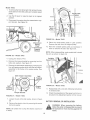
INSTALLING THE BATTERY
Negative
Terminal
¢
1. Raise the seat.
2. Make certain the positive cable (heavy red wire)
and negative cable (heavy black wire) are routed
outside the battery opening.
Positive
al
Battery
Drain
Tube
3. Place the battery inside the opening so that the
positive terminal is toward the front of the unit. See
figure 3. Route the battery drain tube down beside
the battery.
4. Remove the hex bolt from the positive ( + ) terminal.
Place the positive cable on the positive terminal.
-,,-------See
figure 4. Secure with hex bolt. Be careful not
to lose the nut inside the terminal.
5. Secure the negative cable to the negative ( - ) terminal in the same manner. Replace the battery
cover over the positive terminal. Lower the seat.
Red
(Positive)
Cable
;k
(Negative)
Cable
FIGURE 4.
Drain
Tube
Cable
_-
Reinforcement
Bracket
Transaxle
T'_
6. Insert the drain tube through the cable tie which
is attached to the transaxie reinforcement bracket
on the right side of the unit. Be certain drain tube
is routed away from the wheel rim. Pull on end of
cable tie to tighten (do not collapse drain tube).
Tdm excess end of cable tie.
ATTACHING THE CHUTE DEFLECTOR
Attach the chute deflect_ to the deck, f_lle_j
the i_structions in the separate deck manual packed with
your unit.
the chute deflector has been properly inWARNING: Do not operate your unit unless
stalled.
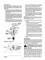
ATTACHING THE STEERING WHEEL
FIGURE 5.
Model 754F On|y:
1. Remove the hex lock nut and cupped washer from
the steering shaft, and remove the steering bellow.
Pry the steering insert off the center of the steering wheel.
Steering Wheel
Insert
Prongs
--
2. Attach one end of steering bellow to the steering
wheel as shown in figure 6A, inset.
3. Position the front wheels of the tractor so they are
pointing straight forward.
4. Place the steering wheel and steering bellow over
the steering shaft, positioning steering wheel as
desired.
Hex Lock Nut
Cupped Washer
FIGURE 6A.--Model
5. Place the washer with the cupped side down over
the steering shaft. Secure with hex lock nut. See
figure 6A.
Steering
Bellow
6. Snap the steering wheel insert over the four spokes
of the steering wheel.
754F
5
tom of the steering wheel (6 o'clock position).
Secure with the cupped washer (cupped side
down) and hex lock nut removed in step 1.
Model 784G Only:
Model 784G is equipped with indicator lights, located
in the steering wheel. The steering wheel must be
assembled as follows for proper operation of the indicator lights.
1. Remove the hex lock nut and cupped washer from
the steering shaft, and remove the steering bellow.
Pry the steering wheel insert off the center of the
steering wheel.
.
Place the indicator wires through the cable tie
located underneath the steering wheel insert. Connect the wires to the same color wire leads in the
steering wheel insert. Tighten the cable tie to hold
the wires securely in position.
.
Snap the steering wheel insert over the four spokes
of the steering wheel, making sure the indicator
lights are positioned at the bottom of the steering
insert (toward the operator).
2. The opening in the steering bellow is wider at one
end than the other. Route the five indicator wires
up through the smaller end of the steering bellow.
Slide steering bellow over steering shaft. Insert the
five indicator wires up through the slot in the steering wheel as shown.
IMPORTANT: Be certain to follow step six exactly to
prevent damage to the indicator lights and wire harness
when using the lawn tractor.
3. Position the front wheels of the tractor so they are
pointing straight forward. Place the steering wheel
over the steering shaft so the wires are at the bot-
.
a. Raise the hood of the tractor, and pull excess
wire down through the dash panel.
Steering
Insert
Oil PTO Clutch
b. Partially tighten the cable tie under the dash
panel so the cable tie is snug, but can still slide
up and down the wire harness. Slide the cable
tie up until it is against the dash panel.
R_ite
c. Turn the steering wheel fully in both directions
(wires will be pulled up into the steering bellow),
then return the steering wheel to the center.
Carefully pull the wires down from the dash
panel, and move cable tie down the wires 1/4
inch.
Black
Hex
Lock
Brownf
Position the cable tie and secure the wire harness
as follows.
\
Green
Cu
Washer
Tighten the cable tie securely. Trim end of cable
tie so at least one inch of the cable tie remains.
Pull bellow up against the bottom of the steering
wheel.
TIRE PRESSURE
Bellow
FIGURE 6B.--Model
The tires on your unit may be over-inflated for shipping
purposes. Reduce the tire pressure before operating
the unit. Recommended operating tire pressure is approximately 12 p.s.i. (check sidewall of tire for tire
manufacturer's recommended pressure).
784G
'Adjustable
Link
_b
J
any circumstances is 30 p.s.i. Equal tire
WARNING: Maximum tire pressure under
pressure should be maintained on all tires.
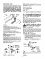
LEVELINGTHE DECK
With unit on hard, level surface, measure the distance
from the bottom edge of the center of the left side of
deck to the ground. Measure the same distance on the
center of the right side of the deck (just behind the
chute area on side discharge units). Or, place the
blades in a straight line, and measure the distance from
the outside edge of the blade tips to the ground.
Adjust the lift link on the left side of the deck as
necessary. See figure 7. Recheck the adjustment.
FIGURE 7.
6
CONTROLS
iiiiiii
iiiiiiiii
iii1,,,11111
i
iiiiii
ii
IGNITION SWITCH
LIGHT SWITCH
The }gnition switch is located
the key to the START position
the engine is running, leave
tion. To stop the engine, turn
tion. See figure 8.
on the dashboard. Turn
to start the engine. When
the key in the ON posithe key to the OFF posi-
The head lamps are operated by pushing the tight
switch located on the dashboard. The head lamps will
only operate when the engine is running. See figure 8.
AMMETER
The ammeter registers the rate of battery charge or
discharge. The ammeter will register on the discharging side with starting the engine. It should register on
the opposite side (charging) when the engine is running in the fast position until the battery is completely
charged. With a fully charged battery or with the engine
idling, the ammeter will not show a charge. See figure 8.
tor when the tractor is not in use to preWARNING: Remove the key from the tracvent accidental starting.
THROTTLE CONTROL
The throttle control is located on the left side of the
dashboard and is used to regulate the engine speed.
See figure 8. The engine should be operated at ful!
throttle (FAST) when operating the mower.
CLUTCH-BRAKE PEDAL
The clutch-brake pedal is located on the left side of the
tractor. See figure 8. Depressing the clutch-brake pedal
partway disengages the clutch. Pressing the pedal all
the way down disengages the clutch and engages the
disc brake.
CHOKE CONTROL
The choke control is located on the right side of the
dashboard and is operated manually. Details for the
choke operation are covered in the separate engine
manual packed with your unit. See figure 8.
NOTE: The clutch.brake pedal must be depressed to
start the engine.
Lift
Lever
Ammeter
SHIFT LEVER
Light
The shift lever is located on the right fender and has
three positions, FORWARD,
NEUTRAL and REVERSE. See figure 9. The clutch-brake pedal must be
depressed and the lawn tractor must not be moving
when shifting gears. Do not force the shift lever.
Release the clutch-brake pedal slightly to line up the
shifting collar in the transmission. Then try to shift
gears.
Control
Clutch-Brakl
Pedal
Shift
Ignition
Switch -Parking f_p
Brake
FIGURE 8A.--Model
754F
Light
Switch
Ammeter
Throttle
FIGURE 9.
Pedal
PARKING BRAKE
To set the parking brake, depress the clutch-brake
pedal, pull up the parking brake knob and release the
clutch-brake pedal. It will stay in the raised position.
To release the parking brake, depress and release the
clutch-brake pedal. See figure 8.
:ch
Parking
Brake
FIGURE 8B.--Model
PTO
Switch
NOTE: The parking brake must be set {f the operator
leaves the seat with the engine running.
784F
7
SPEED CONTROL LEVER
NOTE: The PTO switch must be in OFF position when
starting the engine, when shifting into reverse and ff the
operator leaves the seat.
The speed control lever is located on the left fender.
It allows you to regulate the ground speed of the lawn
tractor. See figure 10. To select the ground speed,
depress clutch pedal. Push speed control lever outward
and move backward to slow lawn tractor, move forward
to increase speed. When desired speed has been obtained, release lever in that position. Whenever clutch
is engaged, unit will automatically go to the pre-set
speed.
CUTTING CONTROLS
A, LIFT LEVER
Model 754F:
The lift lever is used to raise and lower the cutting deck
and to engage and disengage the blades. Pulling it all
the way back and locking it disengages the blades.
Speed
Control
Lever
NOTE: The lift lever must be in the disengaged position when starting the engine, when shiftinginto reverse
and if the operator leaves the seat. See figure 12.
Model 784G:
The lift lever is located on the right side of the lawn tractor. It is used to raise and lower the cutting deck (which
sets the cutting height) and other attachments. Move
the lift lever outward, select the desired cutting height
and release the lever. See figure 12.
FIGURE 10.
when the deck is raised. You must place
WARNING: The blade does not shut off
the PTO switch in the OFF position.
INDICATOR LIGHTS (Model 784G Only)
B. DECK LIFT INDICATOR
Three indicator lights are located in the steering wheel.
If a light illuminates when attempting to start the unit,
proceed as follows.
The deck lift indicator marks the position being used
for the lift lever. Select the lift lever position desired,
press the indicator lever outward, move it to the position immediately below the lift lever and release the indicator lever. See figure 12.
CLUTCH--Depress
the clutch pedal.
PTO--Place
PTO switch in the OFF position.
OIL--Check the crankcase oil level, and add oil as required.
C. SETTING THE CUTTING
POWER TAKE-OFF (PTO) SWITCH
1. Select the position for the lift lever which gives the
desired cutting height. Move the deck lift indicator
so that the lift lever can be returned to the same
position after it is raised,
(Model 784G Only)
The PTO switch is located on the right side of the
dashboard. See figure 11. The PTO switch must be in
the OFF position (down) when starting the engine, when
shifting into reverse and if the operator leaves the seat.
2. Move the deck wheels to the hole location so the
wheels are 1/4to 1/2inch above the ground,
To engage the PTO switch, pull knob out and lift up
to ON position, then release. The knob will return to
RUN position. See figure 11.
Lever
ON Position
F
OFF
Position
<_-_---L__J ON
Position
FIGURE 11.--Model
HEIGHT
RUN Position
OFF Position
RUN
Position
784G Only
FIGURE 12.
8
OPERATION
2 Depress the c_utch@rake _da_ and set the park,°
[ng brake
3, P_ace the sh_ft lever in the NEUTRAL posit on
4
Set the throttle ceetro$ in the FAST post}on.
5
P_s_out the choke contro_ (a warm engne may not
require choking}
6. T_m the gn tion key te the nght to the
o
rice. After the engne s_arts _ebase the key _tw[_
return to the ON position
NOTE Protect dse sta£er Iite by
s d several
_
se
_r m
can damage the
ate
I5
motor,,
7_ Push choke knob in gradually, Move the throttle
contro_ to desired engine speed.
GA$ AND OIL NLL-UP
Se
the engine
Hne and o[_ as inst_l
i_sthe separate engine manua_ packed with your tractor. Read instructions ca_efuHy_
NOTE: YOuTtractor is
small
t d oNmay be
Turn the ignition key to the [eft to the OFF posit on_
Remove the key' to prevent accidenta_ starling
t o_l; howe_er, a
t from the
, Do
_PORTA_T:
If you stdke afo
n
the
angae Re
wire from spark p_ug Ynorough_y
spect the unit fe_ any damage and repair the damage
before restart ng and operat ng the mower
r_ot
WARN_NG:
r fH_ fue_ tank _ndoo_s_
w_th engine mnn_ng or while engine _s hot
_: ff any
ring
_PORTANT:
This unit s equ
with a aafe_y _nter_O¢_ system fer your p
orL The pu
o_the
sdety intedeck system is te p_event the engne from
cranking or starling unless the c_utch.-brake pedal is
depressed and the tilt fever is in the disengaged posi°
t_on (Model 754F} or the PTO swath s _n the OFF postion (Mode 784G) In add rice, the _ifl _ever must be in
the disengaged position (Mode_ 754F) or the PTO
switch must be in the OFF position (Medal 784G}, when
the unit s put eta reverse or the engine will shut off.
If the operater leawss the seat with the lift tever eng
switch eng
(
e_
)
and/o_ w thout
ng the
ing bake Lhe eng r_ewi_
shut off
WA_[NG:
Interlock
because
Do not
_t s _
rate the tra6to_
IS
y dev_ce_
I
Set the des_ed curt ng heght,
2
Stad the eegne as _nst_ueted prevous_y,.
3 Move throttle centre/te full thrett_e to prevent strain
on the engine and to operate
hme_ts
4, P_ace the shfl
fo_
R
I
Mode_ 754_: P_ace the
ENGAGED position
fi
stered, £elet to the
19.
_AR_G:
Before operating
yo_
fo_
_hee_
_ lawn t
r_ be 6eda_n to
the _ext aeetion_"
dng the Lawn Tractook '_ Operate your tractor in an open area
when operating fo_ the first t_me,,
ff the
9ned
are
on
RS£
poe
n either the FOR
P_s£e
the
S
© or
['O_ _eve[
n des red _eit}en Use fi_st speed position when
operating the tracter for the fi_st time_
[ewer n the ©_S
Mode_ 784G: P_ac:e the PTO sw_tch in the OFF
WARN_G:
_ng _p
9
Look 'to the _ear
re back°
r
5. Release the parking brake by depressing the
clutch-brake pedal. Release clutch-brake pedal
slowly to put unit into motion.
6. The lawn tractor is brought to a stop by depressing the clutch-brake pedal.
NOTE: When operating the unit initially, there will be little
difference between the highest two speeds until after
the belts have seated themselves into the pulleys during the break-in period.
Be sure that the lawn is clear of stones, sticks, wire,
or o*,her obiects which could damage _.ractoror eng'me.
For best results and to insure more even grass distribution, do not mow when lawn is excessively wet.
FIGURE 13.
The important point is this: When operating the lawn
tractor beside a wall or fence, against or on top of a
curb, driving around an object, or in any other similar
situation, turn the steering wheel gradually to pull
away from the object or curb so the rear of the tractor
does not swing out and hit the object or go over the
curb.
position for any reason, disengage the
WARNING: Before leaving the operator's
blades, place the shift lever in neutral,
engage the parking brake, shut engine off
and remove the key.
When stopping the unit to empty a grass bag, etc.,
follow the instructions above. This procedure will also
eliminate "browning" the grass, which is caused by hot
exhaust gases from a running engine.
WARNING: If operating this lawn tractor
near a drop-off in the ground, do not make
a sharp turn. The rear wheel turns outward
(see figure 13B) and could lose ground
contact, which could cause the vehicle to
tLp o'_er.
If unit stalls with speed control in high speed, or if unit
will not operate with speed control lever in a low speed
position, proceed as follows.
1. Place shift lever in NEUTRAL.
OPERATING THE CUTTING BLADES
2. Restart engine.
The cutting blades may be engaged while the lawn tractor is moving or standing still. DO NOT engage the cutting blades abruptly as the sudden belt tension on the
pulley may cause the engine to stall.
3. Place speed control lever in HIGH speed position.
4. Release clutch-brake
pedal fully.
5. Depress clutch-brake
pedal.
6. Place speed control lever in desired position.
7. Place shift lever in either
FORWARD
or
REVERSE, and follow normal operating procedures.
_
the discharge opening, the blades or any
WARNING: Keep feet and hands away from
part of the deck. When the unit is used for
other than mowing operations, the blade
drive should be disengaged.
Move the lift lever into the DISENGAGED position to
raise the deck and disengage the blades
STEERING THE LAWN TRACTOR
GRASS COLLECTORAVAILABLE
'(our |our wheel sleet'rag lawn tractor _s des'tgned for
optimum maneuverability. It is important to understand
how it operates before using the lawn tractor.
Grass Collector Model 190063 is available as optional
equipment.
If the wheels are pointing straight forward
4s- 4so
and the steering wheel is turned less than
approximately 45 °, only the front wheels
\V=_/j
turn. See figure 13A. When the steering
wheel is turned sharply (more than approximately 45°),
the rear wheels also turn, but in the opposite direction
as the front wheels to provide a very small turning
radius. See figure 13B.
operated
entireshould
grass catcher
WARNING:without
The the
mower
not be
or chute deflector in place.
NOTE: Under normal usage bag material is subject to
wear, and should be checked periodically. Be sure any
replacement bag complies with the mower manufacturer's recommendations. For replacement bags, use
only factory authorized replacement bag.
10
w
4. Reiease the c_utchobrake pedai completely, then
s_ow_ydepress the pedal aii the way (belt wiil be
aH the way to the outside of the bottom pultey}.
Ho_d the pedal in this position.
ADJUSTMENTS
SEAT AWUSTMENT
T_hoseat may be adiusted to different posiflons_ Refer
to At_acnmg the Seat" in assembly instructions.
5. Turn the engine offl
6. After engine stops completely, re_ease the clutchbrake pedal.
DECK LEVEUN_ ADJUSTMENT
_f a.n _ neven cut is obtainea. _ne deck may be leveled
by IoHowing instr_Jctions at end of sssemMy section.
7_ Unscrew the parking brake knob. Remove the
transmission cover by removing two truss head
screws.
CUTT_N8 DECK ENGAGEMENT ABJUST_IENT
Th _ cutting dock engagement may be adiusted to make
cer:a_n aec_ s a_sengaged dnen _ift _ever is in the
a_senga{aed sos_t_on, or _o obtain more drive in the
cutting positions. Correct adjustment as follows.
8. Disconnect the speed selector rod from the
vadaMe speed pulley by removing the cotter pin
and flat washer and Iiffing rod off the 3/8" pin. See
figure 15.
With the engine off, place the _ift lever in the highest
cutting
position (first position). Remove the cotter pin
and fiat washer which secure the disengagement rod
to the stabilizer shaft assembly_ See figure 14. Shorten
the rod by threading it in until the ferrule is against the
back of the s_ot in the _ift shaft assembly, and the rod
tines up with the ho_e in the stabilizer shaft. For more
be_t tension the disengagement rod must be _ength..
ened_ To decrease belt tension the disengagement rod
must be shortened_
Check the adiustment by placing the iift iever in the
disengaged position° The deck should move up and forward, allowing the be_t to become _oose. Start and test
for disengagement. Repeat procedure as necessary.
FIGURE 15.
9. Disconnect the speed control _inkfrom the variable
speed torque bracket by removing the cotter pin
and fiat washer. See figure 16.
@
SPEED CONTROL ABJ_$T_E_T
_OTE: When operating the unit in/tinily or at,_r replac ._
ing the brits, there wifl be Htt_edifference between the
highest two ,speeds until a£er the belts have gone
t,ffrough a bmakqn period and have seated themselves
into the pufleys°
To adjust the speed control, proceed as fellows..
1 Start the engine.
2. Place the shift lever in _eutral
3. P_ace the speed
position.
contro_ _ever in high speed
F_GU_E l_o_Viewed
11
From Beneath
Tractor
10. Placespeedcontrolleverin first speedposition.
Adjustspeedselectorrodas follows.
a. Pushrodtowardtherearofthetractor,against
the endof the slot in the speedcontrollever
assembly,
b. Turnrodintooroutoftheferruleuntilitfitsfreelyoverthe3/8"pinonthevariablespeedpulley
(turnclockwiseto shortenrod, counterclockwiseto lengthenrod).
c. Afterrod is adjustedto fit overpin, thenturn
rodfour (4) full turns counterclockwise. Move
speed control lever to second positioh. Attach
rod to pin on variable speed torque bracket, using the flat washer and cotter pin.
Q
Hex Nut
Lock Washer Tie Rod
End
Dimension "B" should be approximately 1/8" less than
Dimension "A." See figure 19. To increase Dimension
"B," screw tie rod into tie rod end. To decrease Dimension "B," unscrew tie rod from tie rod end. Reassemble tie rod. Check dimensions. Readjust if necessary.
Castle Nut
Cotter Pin
_'_
Hex
Nut
FIGURE 18.
11. Adjust the brake by removing the cotter pin.
Tighten the nut by hand until the brake lever locks
against the bracket on the transaxle. See figure !7.
_
Tie
Rod
Bracket
On Transaxle
,............
I , i
Q
Front
Brake
Lever
-
I-
FIGURE 17.
B ........
,(118" less than A)
==l
FIGURE 19.
12. Push clutch-brake pedal forward until resistance
is felt. Adjust the speed control link in or out until
it fits over the pin on the torque bracket. Then
shorten two full turns. Secure to pin on torque
bracket using flat washer and cotter pin.
If any further adjustment of the front or rear wheel steering mechanism is needed, the adjustment should be
performed by your authorized service dealer.
13. Back the castle nut on the brake off ! or 2 notches,
till the hole in the brake mounting pin aligns with
a slot in the castle nut. Secure with cotter pin.
CARBURETORADJUSTMENT
WARNING: If any adjustments are made to
the engine while the engine is running
(e.g. carburetor), disengage all clutches
and blades. Keep clear of all moving parts.
Be careful of heated surfaces and muffler.
WHEEL ADJUSTMENT
The caster (forward slant of the king pin) and the
camber (tilt of the wheels out at the top) require no adjustment, Automotive steering principles have been
used to determine the caster and camber on the tractor. The front wheels should toe-in 1/8 inch,
Minor carburetor adjustment may be required to
compensate for differences in fuel, temperature,
altitude and load. To adjust the carburetor, refer to the
separate engine manual packed with your unit.
To adjust the toe-in, follow these steps.
1. Remove the hex nut and lock washer, and drop
the tie rod end from the axle bracket. See figure 18.
NOTE: A dirty air cleaner will cause an engine to run
rough. Be certain air cleaner is clean and attached to
the carburetor before adjusting carburetor. Refer to the
separate engine manual
2. Loosen the hex jam nut on tie rod.
3. Adjust the tie rod assembly for correct toe-in.
12
The steering box assembly has a grease fitting.
However,
it should not require
lubrication.
If
disassembled for any reason, lubricate with 4 oz. of
#251 E.P. grease, part number 737-3007,
BRAKE ADJUSTMENT
During normal operation of this machine, the brake is
subject to wear and will require periodic examination
and adjustment.
The steering shaft should be lubricated with light oil at
least once a season,
_
ARNING:
Do not the
have
the engine running
when
you adjust
brake.
If brake adjustment is required, refer to step numbers
11, 12 and 13 of the Speed Control Adjustment section.
i
iii1,,,
i
m
ill
LUBRICATION
iiiiiiiiiiiiiiiiii
iiii
il
iiiii
disconnect spark plug wire before cleanWARNING:
Always stop engine and
ing, lubricating or doing any kind of work
on lawn tractor.
_
Steering Gears
FRONTWHEELS
FIGURE 21.
The front wheels are provided with grease fittings.
Lubricate front wheels at least once a season with
automotive multi-purpose grease.
TRANSAXLE
The transaxle is lubricated at the factory and does not
require checking, if disassembled for any reasor_,
lubricate with 32 oz. of Shell grease, part number
737-0148.
REAR WHEELS AND U-JOINTS
There are grease fittings provided on the rear wheel
bearing housings and U-joints. Lubricate every 25
hours of operation using automotive multi-purpose
grease. See figure 20. The rear tie rod ends have
service-free inserts. Do not oil or grease the ball joints.
PIVOT POINTS
Lubricate all pivot points with light oil at least once a
season.
NOTE: Figure 20 is shown with rear wheel removed.
MAIN'rENANCE
•,
_ik
Do
_,
i
ill
and ground against the engine before per.
WARNING: Disconnect the spark p_g w_re
forming any repairs or maintenance.
TROUBLE SHOOTING
Grease
Ball Joints
Refer to page 19 of this manual for trouble shooting
_n_ormation.
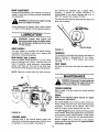
ENGINE
Refer to the separate engine manual for engine
maintenance instructions,
Service air cleaner every 10 hours under normal conditions. Clean every few hours under extremely dusty
conditions. To service the air cleaner, refer to the
separate engine manual packed with your unit.
Grease
Fittings
STEERING GEARS
The spark plug(s) should be cleaned and the gap reset
once a season. Spark plug replacement is recommended at the start of each mo_NinO,_
se_s_; cSeck e_3_e
manual for correct plug type and gap specifications.
Lubricate teeth of the external steering gears with
automotive multi-purpose grease after every 25 hours
of operation or once a season. See figure 21.
Maintain engine oil as instructed in the separate
engine manual packed with your unit. Read and follow
instructions carefully.
FIGURE 20.
13
On Modet 784G on_y, the engine is provided with a
drain hose for your convenience in draining oil from the
crankcase. A clamp secures the drain hose to the side
of the engine_ See figure 22 To drain the oi_, remove
the hose flgm the c_amp and remove the drain plug
from the end of the hose° Be ceAain to replace the drain
p_ug and to use the clamp to secure hose to the engine
before operating,
When sharpening the blades, follow the original angle
of grind as a guide. It is extremely impo_ant that each
cutting edge receives an equa_ amount of grinding to
prevent an unbalanced btade. An unbalanced blade win
cause excessive vibration when rotating at high speeds,
may cause damage to the mower and could break_
causing persona_ injury,
The blade can be tested for balance by balancing it on
a round shaft screwddver_ Remove metal from the
heavy side until it balances evenly.
NOTEs It is recommended that the blade always be
removed fkom the adapter for the best test of balance_
C. Reassembly
Before reassembling the blade and the blade adapter
to the unit, lubricate the spindle and the inner surface
of the blade adapter with Hght oil_ Lubricating the bo_t
holes, botts and inner surface of the nuts with _ight oil
is also recommended A 4 oz, plastic bottle of Hght oii
_ubdcant is avai_aMe Order part number 737_0170,
Engine oil may also be used.
Brain
Drain
............... Hose
FIGURE 22o--Mode[
When replacing blades, be sure to instail the b_ade wth
the side of the blade marked 'Bottom"
(or with part
number) facing the ground when the mower is in the
operating position,
Blade Mounting
784G Only
0LEAN#4G EHG[NE AN# #EOK
To insure safe operation of your unit, ALL nuts and bolts
must be checked periodically for correct tightness.
Any fue_ or oi_ spilled on the machine should be wiped
off promptly Grass, leaves, and other dirt must not be
te_ to accumulate around the cooling fins of _he engine
or on any part of the machine.
Clean the underside
Refer to separate engine
maintenance procedures.
of the deck after each mowing.
CUTTINGBLA#ES
Ao Remova! for Sharpening
Torque
3/8" Da. Boit 375 in Ib. min, 450 in. lb. max.
5/t6" Dia. Bo_t 150 in. _b. rain. 250 in_ lb. max.
manua_ for sit
FUELFILTER
or Replacement
Your unit is equipped with a replaceable [nqine fue_
filter
filter whenever
contamination
or
discoloration
is noticed_ Order replacement filter
through your engine authorized service dea_er,
WARNING: Be sure to disconnect
and
ground the spark phi 9 wire and remove
ignition key before working on the cutting
blade to prevent accidental engine staAo
ingo Protect hands by using heavy g_oves
or a rag to grasp the cutting Madeso
BELT REMOVAL AN# REPLACEMENT
WARNING: Disconnect the spark piu9 wire
a_d ground it against the e_gine_ B_ock the
whee_s of the unit°
1_ Remove the large bo_t and lock washer which holds
the blade and adapter to the blade spindte_
NOT_: Figures 23 through 25 and 27 through 29 are
shown with the unit tipped up _or clarity,, /t is not
necessary to dp the unit to remove the brits.
2_ Remove the Made and adapter from the spindle.
3,, if the blade or blade adapter needs replacing,
remove the two small bo_ts, lock washers and nuts
which hold the biade to the adapter_
However, if tipping the unit is desired, remove the bat,°
tery from the uniL To prevent gasoline leakage, drain
the gasoline, or remove the fue_ tank cap, place a thin
piece of p_astic over the neck of the fuei tank and sc_ew
on the cap. Be certain to remove the p_astic when
finished changing the belts° Block unit securely.
B° Sharpening
Remove the cutting blades by following the directions
of the preceding section.
14
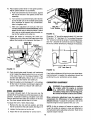
REAR DRIVE BELT
1. U
the
tr_
head
cover.
_ake k_.
_ic.h _ure
th_
_¢er.
the _o
is_n
2. Disconnect the _
rod from the
variable _
pulley by ren'_ving the co_er _n
and fiat
r arid lifting _ off the 3/8" pin.
Refer to figure 15.
Belt Guard
3. Push the idler pulley toward the right side of the
unff. Lift the Wit over the idler pulley.
FIGURE 24.--Model
754F
4. Remove the belt from the variable speed pulley
and transmission pulley.
5. Re_ace
belt, and reassemble
in reverse order.
6. Place the clutch-brake ped_ in park posltion.
6. Adjust: the speed control as instructed in adjustment _ion.
7. Push
on the
the belt off the e_ine
the engine pulley.
8.
DRIVE
_'el
754F:
1. To remove the front drive belt, first
the rear
dr_e belt from t,he idler pulley and variable
2. Place the lift lever in the di_ngaged
e
puffey, and lift
and remove the belt from
the clutch-brake _aL
tO _ve the va
|ift the b_t up and off the
NOTE: When
make
the p/ns. _
U_ng the pedal
_
,
speed pu|ley.
belt is
25,
_sltion.
3. Remove the hex boffs (belt k
from the
engine pu|ley _lt guard. _
figure 23.
Va_able
NOTE: When
make certain hex bolts are
in the same locations from which they were
figure 23_
_x
Bolts
O
A
FIGURE 25.--Model
FIGURE 23.--Model
4_
7_F
754F
9.
Unhook the deck belt from the engine pulley.
5. Rem_ovethe _ _
ng scre_ on each
of the _ame which h._d the engine pulley
guard to the frame. _
figure 24. R
e_ine
belt guard by s|ipping it
in
side
belt
the
and
ble with a new belt, foffowingin
order.
10. Check the adj
of the
in the Adj_tment _=tion
11.
the
merit
15
_
of this manual.
s
_ im
of this manual.
in _ust-
Model784G:
1 Toremovethefrontdrivebelt,firstremovetherear
drivebeltfromtheidJerpulleyandvariablespeed
2, Usethe liA _everto raisethe deckto its highest
3, Disconnect
thespringfromthetransmission
sup_
portbracket.Seefigure2&
FIGURE 28.--Modem 784G
9. Ptace the clutch-brake peda_ in park position
Remove the belt from the engine pulley.
10. Move the vadable speed pulley as necessary
order to remove the beit See figure 29.
in
Bracket
NOTE: When reassembling, make certain belt is inside
the pins as shown in figure 29.
FIGURE26,--Model784G
4. Unplugthe e_ectdcPTO,,
5, Removethetorquebracketby removingtwo hex
boltsandwashers.Seefigure27.
6 Removethebeltkeeperassemblybyremoving
the
fourseff,
otapping screws which ho_dthe be_tkeeper
assembly to the frame at the engine pulley
figure 27,
See
F_GURE 29o_Mode_
784G
11. Reassemble with a new belt, fo!iowing
Torque
Bracket
12_ Check the adjustment of the Speed control as ino
structed in the Adiustment section of this manual
F_GURE 27o--Mode_ 784G
7_
8_
Loosen the pin at the idler putley_ shown in figure
28.
BATTERY REMOVAL OR _NSTALLAT_ON
Remove the electric dutch by removing the center
bolt and washer.
WARNING: When removing the battery_
follow this order of disassembly to prevent
the screwdriver from sho_ing against the
frame°
NOTE: Be careful not to drop the electric ctutch as ff
is heavy.
16
1. Removethe
COMMONCAUSESFORBATTERYFAILUREARE:
Negative cable.
1.
2.
3.
4.
5.
2. Remove the Positive cable,
To install a battery:
1. Attach the Positive cable.
2. Attach the Negative cable;
6. Battery electrolyte substitutes
7. Freezing of electrolyte
JUMP STARTING
1. Attach the first jumper cable from the Positive terminal of the good battery to the Positive terminal
of the dead battery.
NOTE: THESE FAILURES
WARRANTY.
2. Attach the second jumper cable from the Negative
terminal of the good battery to the FRAME OF THE
UNIT WITH THE DEAD BATTERY.
DO NOT CONSTITUTE
TIRES
Recommended operating tire pressure is approximately
12 p.s.i. (check sidewall of tire for tire manutacturer's
recommended pressure). Maximum tire pressure under
any circumstances is 30 p.s.i. Equal tire pressure
should be maintained on all tires,
cedure could cause sparking, and the gas
WARNING: Failure to use this starting proin either battery could exptode.
_
Overcharging
Undercharging
Lack of water
Loose holds downs andlor corroded conrteCtior_s
Excessive loads
When installing a tire to the rim, be certain rim is clean
and free of rust. Lubricate both the tire and rim
generously. Never inflate to over 30 p.s,i, to seat beads,
BATTERY MAINTENANCE
1. Check periodically (every two weeks or before and
after charging) to be sure electrolyte level is above
the lowest line on battery. Add only distilled water
or a good quality drinking water. NEVER add additional acid or other chemicals to battery after initial activation.
_
2. The battery should be checked with a hydrometer
after every 25 hours of operation. If the specific
gravity is less than 1.225, remove battery and
recharge.
p.s.i.) when seating beads may cause
ARNING: Excessive pressure (over 30
tire/rim assembly to burst with force sufficient to cause serious injury.
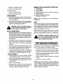
OFF-SEASON
STORAGE
i
3. Coat the terminals and exposed wiring with a thin
coat of grease or petroleum jelly ior longer service
and protection against electrolyte corrosion.
If the machine is to be inoperative for a period longer
than 30 days, prepare for storage as follows.
4. The battery should be kept clean. Any deposits of
acid should be neutralized with soda and water.
Be careful not to get this solution in the cells.
2. Lubricate all lubrication points. Wipe the entire
machine with an oiled rag to protect the surfaces.
1. Clean the engine and the entire unit thoroughly.
3. Refer to the separate engine manual for correct
engine storage instructions.
tATTERY STORAGE
1. Charge battery using normal methods. NEVER
store discharged battery as it will not recover.
4. Refer to battery storage instructions
column.
2. When storing battery for extended periods, disconnect battery cables. Removing battery from unit is
recommended.
,
in previous
5. Store unit in a clean, dry area.
NOTE: When storing any type of power equipment in
an unventilated or metal storage shed, care should be
taken to rustproof the equipment. Using a light oil or
silicone, coat the equipment, especially any chains,
springs, bearings and cables.
Store in cold, dry place.
4. Recharge battery whenever the specific gravity is
less than 1.225, before returning to service, or
every two months, whichever occurs first.
17
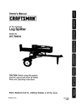
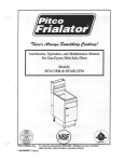
USE THIS SHEET AS A GUIDE TO DETERMINE
SLOPES
WHERE YOU MAY NOT OPERATE
SAFELY.
SIGHT AND HOLD THIS LEVEL WITH A VERTICAL TREE
A POWER POLE
-._{--
A CORNER OF A BUILDING
,_
I
,,d,
CO
I
I
O
I
I
I
WARNING
Do not mow on inclines with a slope in excess of 15 degrees (a rise of approximately 2z/'=feet every 10
feet). A riding mower could overturn and cause serious injury. If operating a walk-behind mower on such
a slope, it is extremely difficult to maintain your footing and you could slip, resulting in serious injury.
Operate RIDING mowers up and down slopes, never across the face of slopes.
Operate WALK-BEHIND
mowers across the face of s_oes,
never up and down slopes.
iiiiii
iii i i
i
,,,,,|,
i
iii
i
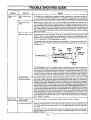
TROUBLE SHOOTING
mli i i i
lllmmllllll
TROUBLE
i i
i
iii
u • m
LOOK FOR
.........
Engine will not
crank
llll
iiii
GUIDE
i
mii i
REMEDY
,, ,,
,,,,
Battery installed incorrectly
The battery must be installed with the negative terminal, identified at the terminal post by (Neg, N
or -), grounded. The positive terminal (Pos, P or +) attaches to the large cable from the solenoid,
The small red wire from the fuse holder or circuit breaker is also attached to the positive terminal.
Blown fuse or circuit
breaker
Replace fuse with 71/2amp. fuse V4x 11/4- Ig, Circuit breaker will reset itself when it cools off. Fuses
or circuit breakers seldom open or fail without a reason. The problem must be corrected. Check for
loose connections in the fuse holder, Replace fuse holder if necessary. A dead short may be in the
cranking or charging circuit where the insulation may have rubbed through and exposed the bare
wire. Replace the wire or repair with electrician's tape if the wire strands have not been damaged.
Note: Look for a wire pinched between body panels, burned by the exhaust pipe or muffler or rubbed
a_Daie_sta m_
p_rt.
Battery is dead or weak
Use a hydrometer to check the condition of the battery. The Specific Gravity (s.g.) should be 1.265
at 80°F. (1.2!5 s.g, minimum needed for cranking engine). The reason for the battery failing must
be determined. (1) Defective battery. Battery will not accept or hold a full charge. (2) Short circuit.
Check for grounded wire. (3) Charging system not working.
,,,,,,,,,,,,,,,,,,,,,,,,,
.......
,, ,
,,,,,,,
,,
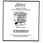
The charging system is an alternator located under the flywheel. It is unregulated and rated 3 amp.
at 3600 r.p.m. A diode (rectifier) is located in the output lead just before the wire harness plug on
the engine side.
Red
Wire
.
_
_- .....
3 AMP DC
(Batt.)
Shrink
Diode
_----====_
To Alternator 0--
Tuble j_---_i/7
:-2___
Black
Wire
AMP AC
(Lamps)
_:_
_'_
Polarized
Plug
The diode changes A.C. to D.C. to charge the battery. A bad diode can either fail to charge the battery or discharge the battery if the alternator is shorted as well as the diode. TO test: (1) Disconnect
charger lead from the battery (small red wire)+ (2) Connect 12 V small test lamp between the 3 amp.
D.C. charge lead and the positive terminal of the battery. (3) With the engine off, the lamp should
not light. If it does, the diode and possibly the alternator should be replaced. (4) Start the engine.
The tamp should light. If it does not, the alternator (stator) or lead wire is bad and should be replaced.
,,,,,,,,
Mechanical
failure
(Wires and switches)
......................
The interlock system includes
two mechanical
activated
switches
which are wired in series in the
circuit used to energize the starter solenoid. While testing the interlock system, you will make the
mower temporarily unsafe by permitting the engine to be started with the blade and clutch engaged.
WARNING: While testing, disengage the clutch, shut off the blade control, set the parking brake and
place the gear shift lever in neutral. Attach a wire (minimum 18 gauge) to the positive terminal of the
bat_ery and t_uch the _ther end t_ the sma__termina_ _n the s__en__d__f the eng_ne d_e_ n_t crank: (1)
There is a loose connection or poor ground. (2) The solenoid may be bad. The solenoid can be checked
by using a heavy wire (#8 gauge minimum) and jumping between the two large terminals. If the engine
cranks, the solenoid is bad. (3) if the engine does not crank when you jump the solenoid, have the
starter motor tested by an authorized engine dealer, if the engine does crank, the problem is with
one of the safety switches, ignition switch or the wire between the fuse holder (or circuit breaker) and
the small termir_al _r_ the soter_(d. N_te: L_k _ e, _-_ _¢tl_
_t t_,e s_t_'_
oT a 6ef_'_ive
switch. Replace if necessary.
.....
,,,,,,,,,,,,,,,,,
,,,,
Engine cranks
but will not start
Throttle
starting
or choke not in
position
....
No spark to spark plug
\
I
Check owner's
guide for correct
,,,,
position for throttle control and choke for starting.
, ,,
Spark plug lead disconnected+ Connect lead. Hold spark plug lead away from engine block about
118". Crank engine. There should be a spark, tf not, have engine repaired at authorized engine service dealer.
Faulty spark plug. To test, remove spark plug. Attach spark plug lead to spark plug. Ground the spark
plug body against the engine block. Crank the engine. The spark plug should fire at the electrode.
Replace if it does not.
19
i
I
TROUBLE
i i
i
i,iiiiii,
iii
TROUBLE SHOOTING
III I II III
III
GUIDE (Continued)
I
LOOK FOR
I
II
REMEDY
....................
No fuel to the carburetor
,,
,,,, ,,,, ,,,,,,,,,,,,,,,,,,,,,,,
Gasoline tank empty. Fill.
Fuel line or in-line fuel filter plugged. Remove and clean fuel line. Replace filter if necessary.
......................................................
Air filter dirty
, ,, ,, ,,,,,,
,,,,,,,,,
If the air cleaner is dirty, the engine may not start. Clean or replace as recommended by the engine
manufacturer,
..........................
, ,,,,,,,
Enginesmokes
Engineloses crankcase Dipsticknotseatedor broken.Replacedefectivepart.
vacuum
Enginebreatherdefective.Replace,
Excessive
Bent or damaged blade
Stop
vibration
spindle
anddamage.Tightenor replaceanydamagedparts.
engine
immediately.
Check all pulleys, blade adapters,
keys and bolts for tightness
,,,,,,,,,,,,,
...........
,,, , ,,,,,,,,,
Bent blade
Stop engine immediately.
Replace damaged blade. Only use original equipment blades,
Engine speed low
Transmission selection
Blades short or dull
Throttle must be set between 3t4 and full throttle.
Use lower transmission speed. The slower your ground speed, the better the quality
Sharpen or replace blades (uncut strip problem only).
.......
Mower will not
discharge
grass or leaves
, ,, ,,,,,,,,,,,,,,
uncut strips
TWO YEAR LIMITED
WARRANTY
For two years from the date of original retail purchase, YaRD-MaN
or replace, at its option, free of charge, F.O.B. factory or authorized
found to be defective in material or workmanship. Transportation
any power equipment unit or attachment are the responsibility of
charges for any parts submitted for replacement under this warranty
unless such return is requested by YaRD-MaN COMPANY.
COMPANY will either repair
service firm, any part or parts
charges for the movement of
the purchaser. Transportation
must be paid by the purchaser
This warranty will not apply to any part which has become inoperative due to misuse, excessive
use, accident, neglect, improper maintenance, alterations, or if the unit has not been operated
and maintained in accordance with the instructions furnished. This warranty does not apply to
the engine, Peerless components, motor, battery (except as noted below) or component parts
thereof. Please refer to the applicable manufacturer's warranty on these items.
A battery which proves defective within ninety (90) days will be replaced without charge. After
90 days but within one hundred twenty (120) days of purchase, YaRD-MaN COMPANY will replace
the defective battery for a charge of 1/2 of the current retail price of the battery in effect at the
date of return.
Warranty on units used commercially
is limited to sixty (60) days.
Warranty service is available through your local authorized service deater or distributor. If you
do not know the dealer or distributor in your area, please write to the Customer Service Department of YaRD-MaN.
The return of a complete unit will not be accepted by the factory unless prior written permission
has been extended by YaRD-MaN.
This express limited warranty is in lieu of all other warranties, express or implied, including any
implied warranty of merchantability. The remedy of replacement is the sole and exclusive remedy
for YaRD-MaN obligations arising from the sale of its products. In no case will YaRD-MaN be
liable for incidental or consequential loss or damage.
This warranty gives you specific legal rights. You may also have other rights which vary from state
to state.
YaRD-MaN
COMPANY • P.O. BOX 360940 • CLEVELAND, OHIO 44136
o! cut.