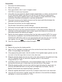
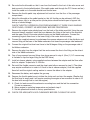
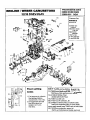
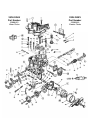
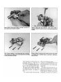
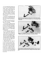
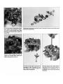
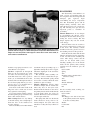
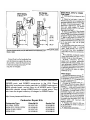
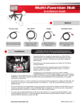
1
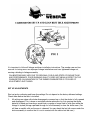
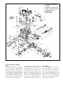
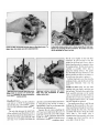
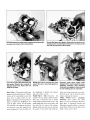
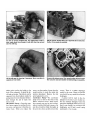
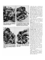
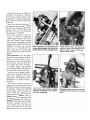
READ AND UNDERSTAND ALL STEPS OF THESE INSTRUCTIONS
BEFORE BEGINNING THIS INSTALLATION.
SUZUKI SAMURAI
For kit no. K600
using (1) Weber 32 DGAV
(Legal in California ONLY for racing vehicles which may NEVER be used upon a highway.)
Tools and equipment needed:
Combination, box or open end wrenches
(metric)
Socket set with 12mm socket
Screwdriver (regular and phillips)
Pliers
Gasket scraper
Cleaning solvent and rags
Knife
Gasket sealer
Parts supplied with installation kit:
1- 32 DGAV Weber Carburetor
1- Manifold Adapter
1- Air Cleaner Adapter
1- Cable Bracket
1- Hardware Kit
Tune-Up Specifications
All tune-up specifications for the Weber Carburetor remain the same as those specified by the
Factory for the original unit. Emissions tune-up should be carried out by a suitably qualified dealer
or independent garage, using infrared gas analyzing equipment.
NOTE: late model vehicles fitted with Emission Control Systems have many vacuum lines and
electrical connections in their fuel systems. It is essential when dismantling, that disconnected lines
be identified with a corresponding number tag or label system. To establish function, locate and
identify the source of each line. Use the under hood emissions diagram, or the factory service
manual for reference when identifying hoses.
Disassembly
1.
Disconnect the vehicle’s battery.
2.
Remove the gas cap.
3.
Drain approximately one (1) quart of engine coolant.
CAUTION: Hot water may be present.
4.
Using either the map inside the vehicle’s engine compartment, or a factory service manual
for your year/make vehicle: tag each hose, vacuum line and electrical wire/connector
attached to the original carburetor and air filter assembly for proper identification during
reassembly. Disconnect all connections once they are identified.
5.
Disconnect and remove the flexible connector and the sheet metal elbow between the
carburetor and the air cleaner housing.
6.
Disconnect the fuel line from the original carburetor.
Plug the end of the fuel line to prevent leakage.
7.
Disconnect the throttle cable from the throttle lever and the cable bracket.
8.
Remove the four (4) nuts that secure the carburetor to the intake manifold. Remove the
carburetor and the spacer/gasket. Insert a clean rag into the intake ports to prevent dirt
and gasket material from entering the engine.
9.
Remove the stock carburetor mounting studs from the intake manifold. NOTE: For correct
stud removal or installation, use stud removal/installation tool or the “double-nut” method.
DOUBLE-NUT METHOD: Install two nuts approximately half way down the stud. Lock the
nuts together. Turn the lower nut for removal and the upper nut for installation.
10. Clean the intake manifold flange surface thoroughly.
ASSEMBLY
11. Remove the rag from the intake manifold.
12. Apply Loc-Tite (supplied) to the 8mm end of the stud into the two holes of the manifold
closer to the passenger side fenderwell.
13. Using appropriate gasket sealer, slide the smaller of the supplied adapter gaskets over the
two studs so that the larger hole is closer to the valve cover.
14. Slide the manifold adapter over the two studs in the same manner as the gasket and using
Loc-Tite (supplied) on the tow allen bolts supplied secure it to the manifold.
Torque the bolts to 7 ft/lbs.
15. Install 8mm studs into threaded holes of the manifold adapter (apply Loc-Tite to the studs)
insuring that the studs go no further than flush with the bottom of the adapter.
16. Slide the remaining gasket over the studs (with the large hole facing the valve cover), followed by the Weber carburetor (insuring that the linkage faces the firewall). The AntiBackfire Valve bracket may require bending for clearance.
17. Slide the supplied cable bracket over the two (2) adapter studs closer to the valve cover.
18. Using the nuts and washers supplied, secure the carburetor to the manifold and adapter;
and tighten, in a criss-cross fashion to 7 ft/lbs.
19. Re-route the throttle cable so that it runs from the firewall to the front of the valve cover and
back around to the installed bracket. (Run cable under and through the PCV hoses and tee.)
Install the cable on to the cable bracket and throttle lever.
20. Remove the throttle pedal stop adjustment bolt and nut from the floor of the passenger
compartment.
21. Adjust throttle cable at the cable bracket so that full throttle can be achieved, AND, the
throttle returns fully to an idle position (choke plates should be held open to bypass idle
kick-up of choke linkage).
CHECK THROTTLE OPERATION FOR FREE MOVEMENT. IF THERE IS ANY BINDING
OR STICKING, CORRECT AS NECESSARY BEFORE PROCEEDING.
22. Remove the original water choke hose from the back of the intake manifold. Using the new
hose and clamps supplied, install the hose between the fitting at the back of the manifold
and the upper fitting of the water choke housing on the Weber carburetor. Connect the
remaining original water hose to the lower fitting of the water choke housing.
23. Connect the supplied vacuum hose between the vacuum advance unit of the distributor and
vacuum fitting on the base of the Weber carburetor that faces the passenger side fenderwell.
24. Connect the original float bowl vent hose to the 90 degree fitting on the passenger side of
the Weber carburetor.
25. Remove the plug from the original fuel line and connect the line to the fitting on the driver’s
side of the Weber carburetor.
26. Cap off any exposed vacuum fittings from hose removal in step 4. (One (1) 1/4” vacuum cap
is included to cap the larger fitting on the EGR Valve.)
27. Install air cleaner adapter using supplied washers between the adapter and the 5mm allen
bolts for adapter. Torque bolts to 10 in/lbs.
28. Re-install the flexible connector and the sheet metal elbow removed in step 5. (The elbow
may require modification in order to fit flush to the air cleaner adapter.) Use the supplied
6mm bolt and the original sealing washer to secure the elbow to the adapter.
29. Reconnect the battery and replace the gas cap.
30. Depress the throttle pedal once to initiate the choke unit and start the engine. (Realize that
the float bowl is empty and it will require cranking the engine a few moments in order to fill
the bowl with enough fuel to start the engine.)
31. A. Check for leaks around the carburetor mounting base and the fuel line connection.
Correct as necessary.
B. Warm engine to operating temperature and recheck step A.
C. Set idle speed and mixture to factory specifications.
32. CHECK FOR ADEQUATE HOOD CLEARANCE BEFORE CLOSING THE HOOD.
REDLINE WEBER
TYPICAL DGV CARB INSTALL VIEWS
These views may vary depending on application. For general assembly assistance only.
32/36 DGAV
Part Number
32/36 DGEV
Part Number
22680.051
Water Choke
22680.033
Electric Choke
It is important to follow all linkage and lever installation instructions. The number one and two
reasons for tuning errors are improper linkage installations and over tightened linkage nut,
causing a binding in linkage assembly.
CALIBRATIONS MAY VARY DUE TO REGIONAL FUELS AND STATE OF ENGINE TUNE
AND PERFORMANCE. POOR RUNNING QUALITY DOES NOT MEAN A DEFECT IN THE
CARBURETOR. AN ADVANTAGE OF THE WEBER CARBURETOR IS ITS EASE OF
ADJUSTMENT AND TUNING.
SET UP ADJUSTMENTS
Start set up by confirming carb base line settings. Do not depend on the factory delivered settings.
Check them before the carb is installed.
1.
All settings are done with choke disengaged or warmed up so that the choke is fully opened
and disengaged. This is done on automatic choke carburetors by first opening the choke
butterfly by hand and inserting a wood block or wedge of some kind to hold open while the
linkage is cycled (linkage operated through its full movement) to clear the choke cam. (You
will hear a metallic click as the cam is released. You can check the fast idle screw under the
choke assembly to confirm that it is not in contact with the choke fast idle cam.)
2.
Set the Idle stop screw (speed screw see fig 1)
by backing out the Idle speed screw until it is
not in contact with the throttle stop lever. Cycle
the linkage again to be sure that the linkage
comes to close without any assistance.
(Checking for linkage bind) Now bring screw
back into contact with the lever and continue
to open or screwing in 1 turn no more than
1 1/2 turns.
3.
Set the mixture screw (see fig 1) by first
screwing in until the screw stops, bottoms out.
DO NOT FORCE OR BIND AS THIS WILL
CAUSE DAMAGE TO THE SCREW AND IT’S
SEAT IN THE BODY OF CARBURETOR.
Back out the screw 2 full turns.
4.
TUNING
BE SURE TO FOLLOW THE NEXT INSTRUCTIONS IN THE PROPER SEQUENCE,
DEVIATION WILL CAUSE THE CARBURETOR TO NOT FUNCTION TO ITS IDEAL
SPECIFICATIONS AND MAY NOT PROVIDE THE PERFORMANCE AND FUEL
ECONOMY AS DESIGNED.
4a Start the engine, the engine will run very slowly more like a tractor. As long as the engine
stays running idle speed is not important at this point.
4b The first thing to do is not set up the idle speed, but to set the idle mixture screw to lean
best idle setting. First, turn in the mixture screw until the engine dies or runs worse, then
back out the screw (recommend turning 1/4 to 1/2 turn at a time). The engine should pick up
speed and begin to smooth out. Back out 1/2 turn more, or until the screw does nothing or
runs worse then turn back to the point where it ran its best. Use your ear, not a scope or
tuning instruments at this point. You want to tune the engine by sound. Adjust to best, fastest
and smoothest running point.
4c Now that the mixture screw is at its best running location, you can adjust the idle speed with
the screw. The screw will be sensitive and should only take 1/4 to 1/2 turns to achieve the
idle speed you like.
Check and set idle to your driving preference. put the car in gear and apply slight load, (AC
on) and set the Idle as you like it. Don’t set it too high, as this will cause excessive clutch
and brake wear. The Idle only needs to be 700 to 900 RPMs with light load or AC on.
5.
Recheck timing and vacuum hook ups. Recheck mixture screw to lean best idle again. If all
is still best and smoothest idle, then confirm and note the final settings.
To confirm settings with the engine running: Start by screwing in the mixture screw and
count the number of turns it takes to bottom out and note if the engine dies. If Idle Mixture
screws are with in 1/2 turn of base line setting then all is well and have fun. Also check the
speed screw and note how many total turns from initial contact. You may have opened
(turned in) the speed screw. Your final setting should be under 2 full turns. Reset the screws
(back in) to the best final settings (per your notes) and go on a test drive and have fun. If the
settings are other than described then you may want to recalibrate the idle circuit (low
speed circuit) to your engines needs. This is done by following the rule of thumb below.
(see next page...)
Simple Rules for low speed calibration
If the mixture screw is more than 2 1/2 turns out, then the idle jet is too lean (too small). When
the mixture screw is less than 1 1/2 turns, then the idle jet is too rich (too large). These assumptions
are based on the fact that the speed screw setting is not opened more than 1 1/2 turns. If the
speed screw has to be opened 2 or more turns then this is also an indication of a lean condition
usually requiring greater change. At times it may appear to be showing signs of richness or
flooding it is really a lean condition. See pictures and notes in the tech 2 article supplied in the
kit instructions, view and please understand the need to keep throttle plate as near to closed as
possible so as not to prematurely expose the transition holes. This is what causes the visible rich
condition, and confirms the need to increase the jet size. JET KITS are available if needed.
EXAMPLE: With the speed screw set at no more than two (2) turns in after contact with the stop
lever; and the best idle occurring with the mixture screw set at 3 turns from bottom, indicates the
need for a larger Idle jet. Achieving the best idle at under 2 turns indicates the need for a smaller
idle jet.
The secret to understanding the critical nature of the carburetor set up and the advantages of a
WEBER over the other carburetors is the idle circuit. Referred to as the low speed circuit by
Weber, this circuit is responsible for 80% of the driving operation. This is the reason that the
Weber should give a fuel economy improvement over most factory carbs along with significant
performance gains. In the worst case you should not see a significant fuel economy loss over
stock, while improving HP and drivability.
The Weber Carburetor is a sequentially timed device to the motor like the distributor. Time taken
in the setup will provide more fun later.
1.
2.
3.
4.
5.
6.
7.
Carburetor-cover assembly
Stud bolt
Carburetor-cover fixing screw
Choke shaft-&-lever assembly
Starting throttle valve
Retaining ring
Dust-seal plate
32/36 DGAV. Drawing courtesy Redline, Inc.
DUAL-DOWNDRAFT REPAIR:
DGAV
The DGAV carburetor is representative of the family of downdraft Weber
carburetors with two venturis and two
parallel throttle shafts. The dual-venturi,
vertical carburetor is standard equipment
on most Italian cars that do not use horizontal Webers such as the DCOE. It is a
favorite conversion carburetor for every
vehicle from Austin to Volkswagen.
The DGAV uses a progressive linkage
from the primary throttle shaft to operate
the secondary throttle, and there is an
automatic choke, power enrichment valve
and accelerator pump to enrich the fuel
mixture as needed. The main casting
includes the two venturis and carries all
the jets and their drilled passages. The
float bowl cover casting carries the power
enrichment valve and float assembly.
DISASSEMBLY
See the sidebar, page 45, for information on special Weber tools. It’s not practical to disassemble this carburetor completely just to fix one part, because you
can do more accidental damage than
could ever result form normal wear. A
little extra time spent diagnosing the
problem can save the grief of breaking a
good part during disassembly.
REASSEMBLY
Shaking throttle-shaft screws requires that you support throttle shaft. End of screw
presents itself at an angle, so a dead-center punch is impossible. Note hammer used
weighs less than five pounds. Shaft support is drive side of 1/4-in. drive socket, or
short section of solid metal rod.
should its long spring be broken or corroded. Renew it as required.
Jets–Blow compressed air through the
main jets, the air-correction jets, emulsion tubes and accelerator-pump jet to
clean them. Never use a wire to probe or
clean a jet; it will disturb the flow characteristics. Blow air through both sides of
the accelerator-pump delivery jet. It is a
one-way valve, so you should be able to
blow through it only one way.
Press down on the center needle of the
full-power valve to make sure it moves
freely against its return spring.
If you removed the auxiliary venturis,
blow through the passage and remove any
burrs or dirt on their surfaces.
Main Casting–Check for any damage
to the main casting. Use a straightedge to
check the base of the carburetor for
excessive warpage.
Remove the idle jets from their holders
and check each jet by holding it up to a
light. Blow through the jet if it’s clogged.
Check the diaphragm of the accelerator
pump for damage.
The automatic choke assembly contains a lot of levers. Check that all operate freely. The bimetallic spring should
not be bent or broken. Check the water
chamber for signs of leakage.
Throttle Shafts–The throttle shafts
should be straight, with no visible wear
where they bear on the nylon seals.
Double-check the threads on the end of
the primary throttle shaft and the threads
on both shafts where the valves are
attached. The throttle valves should have
smooth edges and be flat.
The springs that slide onto the throttle
shafts should be strong and not deformed. Replace the nylon shaft seals
whether or not they show any evidence of
wear.
The disassembly of the DGAV is, in
itself, a lesson on reassembly. After all
the components have been inspected and
damaged
parts
replaced,
begin
reassembling the major components
first. The disassembly photos will be
helpful during assembly. Start with
either the float bowl cover or main casting. The following notes give the most
important points to remember in
reassembly.
Throttle Shafts–There are two dangers
in reassembling the throttle valves;
bending the throttle shafts and not positioning the valves correctly. The first
danger requires only care; the second,
some strategy.
The holes in the valves are oversize so
they can be positioned for a perfect seat
in the bores. The auxiliary venturis
should be removed to give free access to
the attaching screws for this operation.
Install the throttle shafts with all their
linkages and springs in place, then tighten the end nuts before installing the
valves. This strategy assures that the
valves are not moved while you’re
installing anything else on the throttle
shafts. On the primary shaft, working
outward from the innermost part, the
order is:
Nylon washer
Spring
Arm
Shoulder washer, shoulder side to
carburetor casting
Arm
Washer
Throttle bellcrank
Lock tab
Nut
On the secondary shaft, working outward, the order is:
Nylon washer
Spring
Arm–Engage arm with slotted arm
on the primary shaft before slipping
it onto the secondary shaft.
Washer
Lock washer
Nut
Pierce Manifolds is the largest distributor of WEBER carburetors,
WEBER parts, and WEBER conversions in the USA. Pierce
Manifolds manufactures intake manifolds for WEBER carburators,
MGB cylinder heads, and air filters for all WEBER carbs. Pierce
Manifolds rebuilds vintage WEBER carbs to original specs. They
also have the largest inventory of linkages for WEBER carbs.
http://www.piercemanifolds.com
Carburetor Repair Kits
Carburetor Type
32 DGAV, DGEV
32/36 DFV, DFAV, DFEV
32/36 DGAV, DGEV
32/36 DGV
Rebuild Kit
92.3237.05
92.3230.05
92.3237.05
92.3238.05
Gasket Set
92.0108.05
92.0073.05
92.0108.05
92.0108.05
Suzuki Samurai SJ413 General Specifications (stock)
Vehicle type
Vehicle class
Powertrain layout
Body structure
Body material
Seating capacity
Suspension (Front and Rear):
Shock Absorber Specifications
Two-door, hard and soft top
Sport / utility
Front engine, four-wheel drive
Body with chassis frame
Steel
Four
Leaf spring solid axle
Stock Samurai front replacement shocks measure 10.125” collapsed and
15.25” extended, the rear measures 11.75” collapsed and 18.” extended.
Steering
Turning radius
Toe in
Caster angle
King pin angle
Brakes
Front
Rear
Parking brake
16.7 ft. (5.1 m)
0.08 - 0.24 in. (2 - 6 mm)
3° 30'
9° 00'
Type: Power-assisted hydraulic
Disc, floating caliper
Drum leading and trailing
Lever-hand operated
Wheels and Tires
Tire type
Tire size
Front hubs
15 x 5" Steel Wheels (381 x 127 mm)
All-season, steel-belted radial
P205/70R15 (Full-size Spare)
JA and JX: Manual/Automatic
Restraint System
Safety belts: Front and rear lap / shoulder belts
Fuel Economy (EPA Estimates)
City: 23 MPG
Highway: 25 MPG
Engine Type
The engine is an aluminum-block, steel-sleeve 1.3L (81 c.i.) four-cylinder, in-line, 8-valve OHC,
weighs about 200lbs. and generates 64 hp and 74 ft. lbs. of torque.
Bore x Stroke
2.91 in. x 3.03 in. (74 mm x 77 mm)
Displacement
80.8 cu. in. (1.3 liter)
Compression ratio
8.9:1
Induction system
2bbl Carburetor
Horsepower (SAE net)
60 hp @ 6500 rpm (45 kw)
Torque (SAE net)
74 lb.-ft. @ 3500 rpm
Manual Transmission
Clutch
Gear ratios
1st
2nd
3rd
4th
5th
Reverse
Capacities / Calculated Data
Engine oil
Fuel tank
Engine coolant
Transmission oil
Differential gear oil Front
Differential gear oil Rear
Transfer gear box oil
Five-speed, all synchromesh
Dry, single disc, diaphragm spring
3.652
1.947
1.423
1.000
0.795
3.466
Transfer gear ratios
Low (4WD)
High
Differential ratio
373:1
3.7 qts (7.4 U.S. pt.) (3.5 liters)
10.6 U.S. gal. (40.3 liters)
1.34 gal (10.69 U.S. pt.) (5 liters)
Manual (4WD) 2.76 U.S. pt. (1.3 liters)
4.2 U.S. pt. (2.0 liters)
3.2 U.S. pt. (1.5 liters)
1.7 U.S. pt. (0.8 liter)
2.268
1.409
373:1
Samurai VIN # Codes:
first 3 characters = manufacturer's ID (JS4)
next character = car line
next character = series, chassis and restraint system type
next character = engine type
next character = design sequence
next character = body type
next character = "check digit" (tells you what city the vehicle was originally sent to to be sold.)
10th character = model year (G=86, H=87, J=88, K=89, L=90, M=91, N=92, P=93, R=94, S=95)
next character = assembly plant
next six digits = sequential number
Replace the plugs at least every 30,000 miles. Gap them to .028-.032
Timing: 10 degrees BTDC.
Firing order is 1-3-4-2
Wiper blades are 12”
Idle speed should be 750-850 rpm
Exterior Dimensions
Wheelbase
Tread width Front
Tread width Rear
Overall Length
Overall Width (Body)
Overall Height
Interior Dimensions - Rear cargo
Length = 32.5 in (826 mm)
Width = 50.0 in. (1270 mm)
Height = 40.2 in (1021 mm)
79.9 in. (2030 mm)
51.2 in. (1300 mm)
51.6 in. (1310 mm)
135.0 in. (3430 mm)
60.2 in. (1530 mm)
65.6 in. (1665 mm)
Suzuki Parts & Supplies (Web pages / Phone numbers)
1
Asian Auto Parts of Arizona
1-877-885-9341
http://asianautopartsofaz.com
2
Calmini
http://www.calmini.com
3
Hawk Suzuki Parts
1-888-SAMURAI (1-888-726-8724)
http://www.hawksuzukiparts.com/index.html
[email protected]
4
5
6
7
8
North Coast OffRoad
1-866-4X4PART (1-800-494-7278)
http://www.northcoastoffroad.com
PetroWorks Off-Road Products
1-800-952-8915
http://www.petroworks.com
Pierce Manifolds (Source for Weber Carb parts)
http://www.piercemanifolds.com
Roadless Gear (formerly Giri Trading Co.)
1-208-660-6905
http://www.roadlessgear.com
Rocky Road Outfitters
1-888-801-7271
http://www.rocky-road.com/suzuki.html
9
Rod's Samurai Parts
Rod Reyerson - Marshalltown, Iowa
Email: [email protected]
Phone: 641-751-2468 or 641-752-2150
http://www.izook.com/spy/rods/rods.htm
10 Sky Manufacturing
1-541-736-3743
http://www.sky-manufacturing.com
11 Spidertrax
http://www.spidertrax.com/index.html
12 Suzuki John
http://suzukijohn.hypermart.net/index.html
[email protected]
13 Trail Tough
1-877-SUZUKIS (1-877-789-8547)
http://www.trailtough.com
14 Wheeler’s Off-Road
1-541-474-2879
http://www.wheelersoffroad.com
15 Zuki South Samurai parts
http://www.zukisouth.com