1
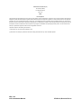
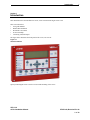
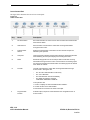
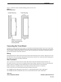
eView Installation Manual
VES, LLC
eView Installation Manual
VF3510-00, Revision E01.06
Issue Date: 10/16/2009
Revision History
Revision
Date
Status
Description
E01.00
08/26/2008
Initial release
Modify original from parent company.
E01.01
09/08/2008
internal edits
Added part number to manual. Change name of remote annunciator from “VES Information
Display” to “eView””. Change contact information from “Central Time” to “Eastern Standard
Time”. Global change of eLITE to Elite Panel. Remove reference to eView without a control
keyswitch. Remove reference to items included with the eView packaging. Global change
from DIL to DIP. Add US units of measurement to metric. Add reference for configuring with
Loop Explorer and eSP Discovery. Change from Syncro and Syncro AS to eLAN and Elite.
Update VES part numbering. Increased font-size of title and centered image on front-cover.
E01.02
09/16/2008
Internal edits
Added RMA and warranty return process in Introduction, Section 1. Added “location security”
to step one of “To complete the installation:”, Installation, Section 3. Identify correct values for
Specifications, Appendix A. Added step#2 to Installation, Section 3, “Remove AC and battery
power to the eLAN or Elite Panel”.
E01.03
11/20/2008
Content changes
under UL project
08CA27859.
Removed VESNet, eNET and firmware reference from first paragraph of Section 2,
Overview. Re-drafted this paragraph to include reference to the buzzer annunciation and
silence, the front-panel controls, the use of level 2 and the RS485 connection. Added low
temperature, high temperature and relative humidity to the Operating Environment section of
Appendix A, Specifications.
Changed document revision on all footers from E01.02 to E01.03.
E01.04
01/14/2009
Content changes
under UL project
08CA27859.
Added maximum input rating of 24 VDC @ 110 mA to Appendix A, Specifications, Electrical.
Changed the range of wire sizes from “18 through 24 AWG” to “14 through 24 AWG” on page
10 of 16 in Section 3, Installation, Before You Begin. This change was performed to be
consistent with terminal block information provided in Appendix A, Specifications Electrical.
Replaced VES logo header on cover. Corrected header spacing. Removed page count from
back cover. Page count changed from 17 to 16. Changed inconsistent header spacing to
consistent spacing throughout document. Corrected spelling.
Changed the document revision on all footers from E01.03 to E01.04.
E01.06
02/05/2009
Non-content
changes
Updated photo on front cover and in Section 1, Introduction. Changed dimensions from
metric to US standard in Section 3, Installation, Mounting. Replaced VES logo on legal page.
E01.06
10/16/2009
Non-content
changes
Added RS panel illustration to Section 3, Installation.
VES, LLC
eView Installation Manual
VF3510-00, Revision E01.06
Underwriters Laboratories (UL)
File number (S 8485)
Fire Alarm Equipment
VES, LCC
NFPA
FCC Compliance
This equipment has been tested and found to comply with the limits for a Class A digital device, pursuant to Part 15 of the FCC Rules. These limits are
designed to provide reasonable protection against harmful interference when the equipment is operated in a commercial environment. This equipment
generates, uses, and can radiate radio frequency energy and, if not installed and used in accordance with the Installation Manual, may cause harmful
interference to radio communications. Operation of this equipment in a residential area is likely to cause harmful interference in which case the user will
be required to correct the interference at his own expense. Any changes or modifications not expressly approved by VES, LCC could void the user’s
authority to operate this equipment under the rules and regulations of the FCC.
Operation is subject to the following two conditions:
(1) This device may not cause harmful interference, and
(2) This device must accept any interference received, including interference that may cause undesired operation.
VES, LLC
eView Installation Manual
VF3510-00, Revision E01.06
Copyright © 2009 by VES, LLC
All rights reserved
VES is a registered trademark of VES, LLC.
All other product or service names are the property of their respective owners.
VES, LLC
eView Installation Manual
VF3510-00, Revision E01.06
i
Contents
Section 1
Introduction
Using This Manual . . . . . . . . . . . . . . . . . . . . . . . . . . . . . . . . . . . . . . . . . . . . . . . . . . . . . . . . . . . . 2
Related Documentation . . . . . . . . . . . . . . . . . . . . . . . . . . . . . . . . . . . . . . . . . . . . . . . . . . . . . . . . 2
Document Conventions . . . . . . . . . . . . . . . . . . . . . . . . . . . . . . . . . . . . . . . . . . . . . . . . . . . . . . . . 2
Part Numbers . . . . . . . . . . . . . . . . . . . . . . . . . . . . . . . . . . . . . . . . . . . . . . . . . . . . . . . . . . . . . . 2
Writing styles . . . . . . . . . . . . . . . . . . . . . . . . . . . . . . . . . . . . . . . . . . . . . . . . . . . . . . . . . . . . . . . 2
If You Need Help . . . . . . . . . . . . . . . . . . . . . . . . . . . . . . . . . . . . . . . . . . . . . . . . . . . . . . . . . . . . . . 3
Contacting VES Tech Support . . . . . . . . . . . . . . . . . . . . . . . . . . . . . . . . . . . . . . . . . . . . . . . . . . . 3
RMA Returns Required . . . . . . . . . . . . . . . . . . . . . . . . . . . . . . . . . . . . . . . . . . . . . . . . . . . . . . . 3
Warranty Returns . . . . . . . . . . . . . . . . . . . . . . . . . . . . . . . . . . . . . . . . . . . . . . . . . . . . . . . . . . . 3
Advanced Replacements . . . . . . . . . . . . . . . . . . . . . . . . . . . . . . . . . . . . . . . . . . . . . . . . . . . . . 4
Suspect-Product Testing . . . . . . . . . . . . . . . . . . . . . . . . . . . . . . . . . . . . . . . . . . . . . . . . . . . . . . 4
Product Return Address . . . . . . . . . . . . . . . . . . . . . . . . . . . . . . . . . . . . . . . . . . . . . . . . . . . . . . . 4
Section 2
Overview
Controls and Indicators . . . . . . . . . . . . . . . . . . . . . . . . . . . . . . . . . . . . . . . . . . . . . . . . . . . . . . . . 6
Controls . . . . . . . . . . . . . . . . . . . . . . . . . . . . . . . . . . . . . . . . . . . . . . . . . . . . . . . . . . . . . . . . . . . 7
Indicators . . . . . . . . . . . . . . . . . . . . . . . . . . . . . . . . . . . . . . . . . . . . . . . . . . . . . . . . . . . . . . . . . 9
Section 3
Installation
Before You Begin . . . . . . . . . . . . . . . . . . . . . . . . . . . . . . . . . . . . . . . . . . . . . . . . . . . . . . . . . . . . 10
Mounting . . . . . . . . . . . . . . . . . . . . . . . . . . . . . . . . . . . . . . . . . . . . . . . . . . . . . . . . . . . . . . . . . . . 10
Connecting the Circuit Board . . . . . . . . . . . . . . . . . . . . . . . . . . . . . . . . . . . . . . . . . . . . . . . . . . 11
Wiring . . . . . . . . . . . . . . . . . . . . . . . . . . . . . . . . . . . . . . . . . . . . . . . . . . . . . . . . . . . . . . . . . . . 11
Data Termination . . . . . . . . . . . . . . . . . . . . . . . . . . . . . . . . . . . . . . . . . . . . . . . . . . . . . . . . . . 11
Connecting to the eLAN or Elite Panel . . . . . . . . . . . . . . . . . . . . . . . . . . . . . . . . . . . . . . . . . . 12
Connecting to the eLAN-RS or Elite-RS Panel . . . . . . . . . . . . . . . . . . . . . . . . . . . . . . . . . . . . 12
Connecting to the eView . . . . . . . . . . . . . . . . . . . . . . . . . . . . . . . . . . . . . . . . . . . . . . . . . . . . . 13
Testing the Installation . . . . . . . . . . . . . . . . . . . . . . . . . . . . . . . . . . . . . . . . . . . . . . . . . . . . . . . . 14
Processor and Watchdog Reset . . . . . . . . . . . . . . . . . . . . . . . . . . . . . . . . . . . . . . . . . . . . . . . . 15
VES, LLC
eView Installation Manual
VF3510-00, Revision E01.06
ii
Contents
Appendix A
Specifications
Electrical . . . . . . . . . . . . . . . . . . . . . . . . . . . . . . . . . . . . . . . . . . . . . . . . . . . . . . . . . . . . . . . . . . . 16
Communications . . . . . . . . . . . . . . . . . . . . . . . . . . . . . . . . . . . . . . . . . . . . . . . . . . . . . . . . . . . . 16
Operating Environment . . . . . . . . . . . . . . . . . . . . . . . . . . . . . . . . . . . . . . . . . . . . . . . . . . . . . . . 16
Physical Specifications . . . . . . . . . . . . . . . . . . . . . . . . . . . . . . . . . . . . . . . . . . . . . . . . . . . . . . . 16
VES, LLC
eView Installation Manual
VF3510-00, Revision E01.06
iii
Contents
This page intentionally left blank.
VES, LLC
eView Installation Manual
VF3510-00, Revision E01.06
Introduction
1
Section 1
Introduction
This manual describes the installation of eView, VF1172-00 and trim ring kit VF1173-00.
This section describes:
• Using This Manual
• Related Documentation
• Document Conventions
• If You Need Help
• Contacting VES For Repair
The figure below illustrates the front-panel of the eView, VF1172-00:
Figure 1-1
eView Front-Panel
Specify Trim Ring Kit VF1173-00 for recessed-wall-mounting of the eView.
VES, LLC
eView Installation Manual
VF3510-00, Revision E01.06
1 of 16
Introduction
1
Using This Manual
The following sections provide instructions for installing, testing and troubleshooting the eView:
Section 1
Introduction provides document conventions, the technical help-line, repair and return
information.
Section 2
Overview provides a summary features of the eView.
Section 3
Installation describes how to install, configure and troubleshoot the eView.
Appendix A
Specifications provides operating characteristics of the eView.
Related Documentation
The following documents shall be used to provide additional information for installing the eView:
• eLAN H Installation Manual With Releasing VF1615-00, Rev.E05.XX
• eLAN A Installation Manual With Releasing VF1635-00, Rev.E02.XX
• Elite H Installation Manual, VF3515-00, Rev.E02.XX
• Elite A Installation Manual, VF3514-00, Rev.E02.XX
• eMatrix Installation Manual VF3513-00, Rev.E01.XX
Document Conventions
This document contains conventions for part numbers and writing style.
Part Numbers
Part numbers are provided in Section 1 and Appendix B of this manual. Refer to Appendix B, Equipment List for a
complete list of part numbers required for completing this installation.
Writing styles
Before you begin using this installation manual, familiarize yourself with the following stylistic conventions:
Bold type
Indicates text that you must type exactly as it appears or indicates a default value.
Italic type
Denotes a displayed variable, a variable that you must type, or is used for emphasis.
Courier font
Indicates text displayed on a computer screen.
VES, LLC
eView Installation Manual
VF3510-00, Revision E01.06
2 of 16
Introduction
1
If You Need Help
If you need technical support contact VES at (800) 274 - 9514 or email [email protected].
VES technical support is available Monday through Friday, 8:00 AM to 6:00 PM, Eastern Standard Time.
Contacting VES Tech Support
On-site technicians familiar with the product issue should contact VES Tech Support and include the:
• Product part number
• Purchase order or VES order number
• Product serial number
• Current function of the product
• Expected function of the product
• Installation of the product
RMA Returns Required
A Return Material Authorization (RMA) must be assigned to all products returning to VES. VES Tech Support will
assign an RMA to a returning product after recording information collected from the on-site technician. VES cannot
not accept product-returns that do not include an accompanying RMA number.
An RMA number is assigned when:
• A product issue is acknowledged by a VES Tech Support representative
• A product was damaged during shipping
• An order was placed using an incorrect part number *
• An order was placed using an incorrect part quantity *
• An order is no longer required *
* Restocking fees may apply.
Warranty Returns
VES Tech Support can replace a defective product when the original purchase is within the warranty period defined
in the sales contract. Check your sales-contract for more information or contact your VES sales representative about
the warranty period described in your sales-contract.
Warranty products that have been placed in service will be repaired or replaced by VES.
Warranty products that have not been placed in service will be returned to VES stock and an equivalent credit will be
provided to the contractor.
VES, LLC
eView Installation Manual
VF3510-00, Revision E01.06
3 of 16
Introduction
1
Advanced Replacements
Suspect-products that fail to operate in the field can be replaced quickly using the advanced replacement process.
The advanced replacement process is available to all contractors who maintain an acceptable line of credit with VES.
Initiate the advanced replacement process by requesting an RMA number from a VES Tech Support representative.
Advanced replacements can be shipped to your location when the suspect-product is covered under warranty and
when a replacement product is in stock. All advanced replacement products are shipped UPS ground.
Expedited Replacements
Advanced replacements can be expedited at the request of the contractor. Shipping costs associated with this
process are the responsibility of the contractor.
Returning Products
Suspect products returning to VES using the advanced replacement process must be received 30 days from the RMA
issue-date. Contractors can be billed for returning products received following this 30 day period.
Suspect-Product Testing
Suspect-products returned to VES are tested to confirm operating failures experienced in the field.
If the suspect-product is found to be functional, contractors must absorb the following expenses:
• Shipping of the advanced replacement product
• Return-shipping of the suspect-product
• Cost of the advanced replacement product
Product Return Address
Prominently display the RMA number on all packages sent to VES for return.
Ship all return products to:
Attention: RMA # _____________
VES, LLC
620 Allendale Road, Suite 175
King of Prussia, PA. 19406
VES, LLC
eView Installation Manual
VF3510-00, Revision E01.06
4 of 16
Introduction
1
This page intentionally left blank.
VES, LLC
eView Installation Manual
VF3510-00, Revision E01.06
5 of 16
Overview
2
Section 2
Overview
The eView provides annunciation and control while operating on the COMMS ( + , - ) terminals of the eLAN and
Elite Panel. The COMMS ( +, - ) terminals provide an RS485 communication path to devices such as the VES eView.
Front-panel controls and indicators of the eView are identical to those provided on the eLAN and Elite Panel.
Operate Access Level 2 on the eView exactly as performed on the eLAN and Elite Panel.
The RS485 communication path does not support the simultaneous operation of Level 2 on multiple eViews.
Operate Level 2 on one eView at a time when multiple eViews are connected on the RS485 communication path.
The buzzer of the eView can annunciate and silence in unison with the eLAN and the Elite Panel. The buzzer can also
annunciate or silence locally using the front-panel controls of the eView.
Controls and Indicators
The figure below illustrates controls and indicators of the VES eView:
Figure 2-1
Controls and Indicators
13:30 Friday 12 May 2008
AUTO CONFIGURED PANEL
Enable
Access
USE ARROW KEYS TO ENABLE PANEL
PRESS ? FOR HELP
1 2 3
4 5 6
Key
Description
1
LCD display
2
Left-panel-indicators
3
Upper-control-pad
4
Lower-control-pad
5
Right-panel-indicators
6
Access level keyswitch
VES, LLC
eView Installation Manual
VF3510-00, Revision E01.06
6 of 16
Overview
2
Controls
The VES eView contains upper-panel and lower-panel control-pads.
Upper-Control-Pad
The figure below illustrates the eView upper-control-pad:
Figure 2-2
Upper-Control-Pad
Key
Name
Description
1
Central keypad number four
Navigates menu selections to the left.
2
More Fire Events
Displays the number of alarms present on the
eView and overrides the display provided by menu navigation.
3
Exit
Cancels the current menu selection.
4
Central keypad question mark
Provides a “help screen” for the current menu display and also displays status. For example, recommendations are displayed during
alarm or fault conditions. If a menu function is accessed then help
relating to that function will be displayed.
5
Central keypad number three
Navigates menu selections down.
6
Enter
Enables the menu selection.
7
More Events
Displays the number of events present and overrides menu navigation. Provides event status for Fire, Pre-Alarm, Trouble,
Disablements and Other.
8
Central keypad number two
Navigates menu selections to the right.
9
Central keypad number one
Navigates menu selections up.
VES, LLC
eView Installation Manual
VF3510-00, Revision E01.06
7 of 16
Overview
2
Lower-Control-Pad
The figure below illustrates the eView lower-control-pad:
Figure 2-3
Lower-Control-Pad
Key
Name
Description
1
Re-Sound Alarm
Re-sounds the alarm in Access Level 2 when sounders are muted with the
Alarm Silence button.
2
Alarm Silence
Silences NACs connected to the eView after receiving authorization
through Access Level 2.
3
Panel Sounder
Silence
Mutes the internal buzzer of the eView. No other sounder outputs are
affected by this operation.
4
Lamp Test
Tests front-panel indicators and the internal buzzer by illuminating all LEDs
while darkening the front-panel display and sounding the buzzer.
5
Reset
Resets latching inputs such as fire and pre-alarm events after receiving
authorization through Access Level 2. Fault events are non-latching inputs
and cannot be cleared by the Reset button. Non-latching inputs are cleared
when faults are cleared.
6
Fire Drill
Provides a fire drill for the eView after receiving authorization through
Access Level 2. During the drill:
•
•
•
•
The “On Test” LED illuminates continuously
The “Fire” LEDs blink
The internal buzzer sounds intermittently
The display provides the message,
“FIRE DRILL:FIRE DRILL ZONE 00*
To stop the fire drill:
1 Press 4 to display the “SET ACCESS LEVEL 2 MENU”.
2 Provide Access Level 2 authorization.
3 Press Reset or Fire Drill on the lower-control-pad.
7
Programmable
Function
VES, LLC
eView Installation Manual
Activates inputs, outputs or actions defined in the configuration when in
Access Level 2.
VF3510-00, Revision E01.06
8 of 16
Overview
2
Indicators
The VES eView contains left and right panel-indicators.
Left-Panel-Indicators
The figure below illustrates left-panel-indicators:
Figure 2-4
Left-Panel-Indicators
Key
LED
Color
1
Fire, NAC Output State
- Flashing = NACs Activated
- ON Continuous = NACs silenced
- OFF = Panel and NACs Reset
Red
2
Fire, NAC Output State
- Flashing = NACs Activated
- ON Continuous = NACs silenced
- OFF = Panel and NACs Reset
Red
3
AC Power On
Green
4
Pre Alarm
Yellow
5
Fire Output Active
Red
6
On Test
Yellow
7
Panel Sounder Silenced
Yellow
8
Delay Active
Yellow
9
More Events
Yellow
10
Point Bypassed
Yellow
Key
Description
Color
1
1
General Trouble
Yellow
2
2
Power Trouble
Yellow
3
System Trouble
Yellow
4
NAC Trouble
Yellow
5
Supervisory Alarm
Yellow
1
2
3
4
5
6
7
8
9
10
Right Panel Indicators
The figure below illustrates right panel indicators:
Figure 2-5
Right Panel Indicators
3
4
5
VES, LLC
eView Installation Manual
VF3510-00, Revision E01.06
9 of 16
Installation
3
Section 3
Installation
This section provides instructions for connecting cables, mounting and testing the eView.
To complete the installation:
1
Notify the monitoring center and local security that the eLAN or Elite Panel will be temporarily out of service
when installing the eView.
2
Remove the eView from its packaging and check its contents.
3
Mount the eView and connect cabling for power and communication.
4
Applying power to the eView.
5
Configure the eView using eSP Discovery when networking eLAN Panels on the VESNet or configure the
eView using Loop Explorer when networking Elite Panels on the eNet.
Install this product in accordance with NFPA 72, the National Electrical Code and all local codes.
Before You Begin
Before you begin the installation, take a few minutes to review the installation information, gather the required items,
and complete the tasks listed below to make the installation as quick and easy as possible.
Acquire the following items that are not included with the eView, but may be required for the installation:
Item
Quantity
Description
Communication Cabling
1
Specify required lengths of 14 through 24 AWG.
Power Cabling
1
Specify required lengths of 14 through 24 AWG.
Ground Strap
1
A ground strap is required for handling circuit boards.
The ground strap is not provided in the packaging of the eView.
Mounting
Determine the best location for the eView before mounting it. Surface mounting devices should be mounted on a dry,
flat surface. Position the device for mounting so that it is at eye height and level.
Secure the eView to a mounting location using four-screws that are 1/64” in diameter.
The eView should not be mounted in the proximity of heat sources or placed inside enclosures that do not have adequate ventilation.
Cables should be connected using suitable cable connections. If additional cable entry points are required, all debris
caused by drilling of additional cable entries must be cleared before power is applied.
VES, LLC
eView Installation Manual
VF3510-00, Revision E01.06
10 of 16
Installation
3
Figure 3-1 illustrates surface and flush-mounting positions of the eView:
Figure 3-1
Mounting Positions
Secure the eView to a flat
surface using suitable wall
mounting hardware.
Connecting the Circuit Board
Terminate all wiring connections at the single row of terminals located along the bottom of the eView circuit board.
Shielded fire alarm cable such as FP200 and metal-cable-connectors must be used for all connections. The resistance
of any conductor of the data cable must not exceed 25 ohms. The shield of the cable must be connected securely to
the enclosure and to the metal-cable-connector.
Wiring
Wiring should enter the cabinet at the knockouts provided at the back and top of the enclosure. Wiring must not cross
the front of the eView circuit board. Wiring must be dressed away from the eView circuit board when cabling enters
the enclosure at locations other than the knockouts.
Data Termination
Up to 15 devices can be connected to an eLAN or Elite Panel. In and out terminals for data and 24V DC are
provided on each device. All devices are supplied with a push-on-jumper at position J3 on the left of the PCB. This
jumper connects a terminating resistor which needs to be in place for the last device on the data-line.
Remove all jumpers except the last device on the data-line if more than one device is connected.
If there is only one device connected then the jumper should be left in place.
The COMMS LED will flash quickly when a device is communicating with the eLAN or Elite Panel.
The COMMS LED will not illuminate when a device is disconnected on the eLAN or Elite Panel.
VES, LLC
eView Installation Manual
VF3510-00, Revision E01.06
11 of 16
Installation
3
Connecting to the eLAN or Elite Panel
Figure 3-2 illustrates connections to the eLAN or Elite Panel:
Figure 3-2
eLAN or Elite Panel Connections
1 2 3
4
5 6 7 8
9 10 11 12 13 14 15 16 17 18 19 20 21 22 23 24 25 26 27 28 29 30 31 32 33 34 35 36 37 38 39
Key Description
+ - + - + - + - + - + NC C NO NC C NO NC C NO NC C NO NC C NO NAC 1 NAC 2 NAC 3 NAC 4
- + - +
- + - +
- + - +
NO 1
OUT- + IN
- + OUT- + IN- + OUT- + IN - +OUT- + IN NC CFIRE
TROUBLE FIRE 2 SUPERVISORY AUXILARY
OUT
IN
LOOP
4
FIRE +
ROUTING TROUBLE +
ROUTING -
WARNING!
DO NOT PLUG OR UNPLUG RIBBON CABLES WHILE
BOARD IS POWERED.
STATIC SENSITIVE CIRCUITS. OBSERVE STATIC
HANDLING PROCEDURES AT ALL TIMES
1
2
3
4
5
PROGRAMMABLE +
OUTPUT 1. TBL
1.
2. RES
TBL
REMOTE 3. INT
3.
CONTROLINT4. CNT
REMOT
AND
AUX. 4.5. SIL
E
CONTRO
CNT
LINPUT
5. SIL 0V
0
6.
PR1
V
6.
7. PR2
PR1
7.
8. PR3
PR2
6
7
8
9
10
11
12
13
NETWORK
IN
14
15
16
17
18
19
20
21
NETWORK
OUT
22
23
COMMS
AUX
24V
l
l +
ADDITIONAL
I/O BOARDS
l +
IN
LOOP
3
l + l
l + l +
IN
LOOP
2 OUT
TO DISPLAY
IN
LOOP
1OUT
D
C
B
A
A
Connects to COMM IN
+ terminal of eView.
B
Connects to COMM IN
- terminal of eView.
C
Connects to IN 24V
terminal of eView.
D
Connects to IN 0V
terminal of eView.
24VDC
- - + +
BATTERY DISCONNECT
BATTERY LOW
AC POWER FAILURE
GROUND FAULT
CHARGER TROUBLE
REMOTE PSU
Connecting to the eLAN-RS or Elite-RS Panel
Figure 3-3 illustrates connections to the eLAN-RS or Elite-RS Panel:
Figure 3-3
eLAN-RS or Elite-RS Panel Connections
Key Description
B
A
D
C
A
Connects to IN 24V
terminal of eView.
B
Connects to IN 0V
terminal of eView.
38 39 40Connects
41
to COMM IN
C
8 9 10
11 12 13 14
P2T
P2R
L2R
+
-
+
-
24V OUT AUX 24V
15 16 17 18
+
-
NAC 1
+
-
NAC2
19 20 21 22
+
-
+
-
SLC1 OUT SLC1 IN
23 24 25
NC
C
NO
TROUBLE
26 27 28
NC
C
FIRE
NO
29 30 31
NC
C
NO
32 33 34 35
+
-
+
-
SUPERVISORY NET OUT NET IN
+ terminal of eView.
36 37
+
-
COMMS
D+
-
Connects
to COMM IN
- terminal of eView.
+
SLC2 OUT SLC2 IN
More Events
1
General
Disablement
General Trouble
Power Trouble
4
?
2
3
Supervisory
VES, LLC
eView Installation Manual
VF3510-00, Revision E01.06
12 of 16
Installation
3
Connecting to the eView
The eView provides connections for RS485 communication and 24 VDC power.
To provide these connections on the eView:
1
Remove four screws from the front-panel of the eView.
2
Remove the rear cover.
3
Connect RS485 communication to the terminals of COMM1.
4
Connect 24 VDC power to terminals of 0V and +24V.
Figure 3-4 below illustrates eView terminal connections on the Control Unit Board:
Figure 3-1
Device Connections
1
2
3
0V
COMM1
RESET W/DOG
RESET
ADDRESS
ON
1
PF
- +
- +
+24V
COMM2
- +
- +
FIT JUMPER
FOR END OF LINE
COMM2
3
4
K6017 ISS.04
COMM1
KS
2
COMMS
ACTIVE
S1
Key
Name
Description
1
COMM1
Input terminals for RS485 serial bus communication.
2
0V
Negative power terminal ( - ) for 24 VDC return.
3
+24V
Positive power terminal (+) for 24 VDC.
VES, LLC
eView Installation Manual
SERIAL NUMBER
S579US -113290-40
VF3510-00, Revision E01.06
13 of 16
Installation
3
Testing the Installation
Devices connected to the eLAN or Elite Panel must be allocated addresses so that the control panel can identify the
integrity of the circuit path. The address switch should never be set with all switches in the off position.
Provide an address on the switch by setting a binary number from 1 to 15 on the 4 way, DIP switch located at the bottom of the PCB. The order of the addresses is not important but each device must be allocated a different address.
The switch settings for each of the addresses are shown below.
Figure 3-5 illustrates binary addresses 1 to 15 on the eView:
Figure 3-5
Binary Addresses
The black portion of the DIP identifies the switch actuator. An address of 7 is set when actuators of the DIP switch are
“up” on positions 1, 2 and 3.
These settings identify:
•
20 for switch position 1, where 20 = 1
•
21 for switch position 2, where 21 = 2
• 22 for switch position 3, where 22 = 4
The binary address for this DIP is 1 + 2 + 4 = 7
Figure 3-6 illustrates settings for an address of 7 on the DIP switch of the eView:
Figure 3-6
DIP Switch Settings
ON
1
2
3
4
The arrow in the figure above identifies the on position of the DIP when the switch actuator is in the “up” position.
VES, LLC
eView Installation Manual
VF3510-00, Revision E01.06
14 of 16
Installation
3
Processor and Watchdog Reset
The eView is controlled by a microprocessor, which will re-start itself and continue to run if it stops for any reason
due to severe electrical interference such as an electrical storm.
A watchdog (W/DOG) LED indicator latches-on and a fault signal is provided to the eLAN or Elite Panel when the
eView is being subjected to continuous interference.
Press the W//DOG RESET button on the bottom of the PCB if a processor re-start occurs. This resets the
latched fault condition.A switch is also provided to manually re-start the processor PROC RESET.
This switch can be used to ensure that devices begin communicating with the eLAN or Elite Panel in a controlled
manner.
Figure 3-7 illustrates switch settings for addressing, processor reset and watchdog reset:
Figure 3-7
Switch Settings
VES, LLC
eView Installation Manual
VF3510-00, Revision E01.06
15 of 16
Specifications
A
Appendix A
Specifications
This appendix provides specifications for the eView:
Electrical
MAXIMUM INPUT RATING
24 VDC @ 110 mA
STANDBY CURRENT
30 mA
CONNECTOR TERMINALS
Terminals accepts 14 - 24 AWG wire.
MAXIMUM NUMBER OF UNITS
The eLAN and Elite Panel can each power a maximum of four eViews from
the Aux 24V terminals.
Communications
RS485 SERIAL BUS
RS485 two-wire
Maximum distance from control panel: 3900 feet (1200 meters)
Specify Belden 9271 cable.
MAXIMUM NUMBER OF UNITS
The eLAN and Elite can each support a maximum of 15 eViews on the
485 Serial Bus.
Operating Environment
LOW TEMPERATURE
32 +/- 3oF (0 +/- 2oC)
Dry indoor use only
HIGH TEMPERATURE
120+/- 3oF (49 +/- 2oC)
Dry indoor use only
RELATIVE HUMIDITY
93% +/- 2% @ 90 +/- 3oF
(32 +/- 2oC)
This device functions in an
atmosphere of relative humidity up
to 93 percent, non-condensing.
Physical Specifications
ENCLOSURE DIMENSIONS
Shell: 1811/16 “ x 145/16 ” x 33/4 ”
Door: 183/4 ” x 147/16 ” x 11/16”
WEIGHT
11lbs. (5 Kg) maximum
VES, LLC
eView Installation Manual
VF3510-00, Revision E01.06
16 of 16
VES, LLC
eView Installation Manual
VF3510-00, Revision E01.06
16