1
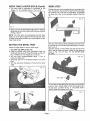
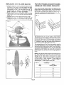
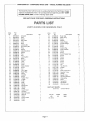
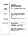
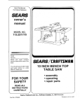
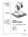
OWNERS
MANUAL
MODEL NO.
900.233550
CAUTION:
Read Rules for
Safe Operation
and instructions
Carefully
8"1/4in. OO___POUNDMITER SAW
Introduction
Operation
Maintenance
Repair Parts
sold by SEARS, ROEBUCK AND CO,, Chicago, IL 60684 USA°
Form No, 875437
Printed in W Germany
Product Made in W Germany
FULL ONE YEAR WARRANTY ON CRAFTSMAN PORTABLE ELECTRIC SAWS
1
if this CRAFTSMAN Saw fails to give complete satisfaction within one year from date of purchase, return it to the nearest
Sears store throughout the U.S Sears wilt repair it, free, If this CRAFTSMAN Saw is used for commercial or rental purposes warranty applies only for 90 days from date of purchase
t
.R
t_
1
THIS WARRANTY GIVES YOU SPECIFIC LEGAL RIGHTS AND YOU MAY ALSO HAVE OTHER RIGHTS WHICH VARY
FROM STATE TO STATE.
...........
!
SEARS, ROEBUCK AND CO,, DEPT, 698/731 A, SEARS TOWER, CHICAGO, IL 60684
t
INTIODUOTION
"(our new 1114in. Compound liter
Saw is a rugged, dependable tool that will miter wood and other materials with
accuracy and repeatability Easy to operate, its the ideal saw for the serious Do-it-Yourselfer
Please take the time to read this Owner's Manual thoroughly Pay particular attention to the safety rules provided
with a thorough understanding of your Miter Saw will you be able to utilize its full potential
Only
SAFETY RULES:
1,
2.
21.
22
23
KEEP GUARDS IN PLACE and in working order,,
REtVlOVE ADJUSTING KEYS AND WRENCHES, Form a habit of checking to see that keys and adjusting wrenches
are removed from tool before turning it on.
KEEP WORK AREA CLEAN. Cluttered areas and benches invite accidents,.
DON'T USE IN DANGEROUS ENVIRONMENT. Don't use power tools in damp or wet locations, or' expose them to
rain. Keep work area well tighted_
KEEP CHILDREN AWAY. All visitors should be kept a safe distance away from work area.
MAKE WORKSHOP KID PROOF with padlocks, master switches, or by removing starter keys,
DON'T FORCE TOOL. It will do the job b_tter and be safer at the rate for which it was designed,
USE RIGHT TOOL. Don't force tool or attachment to do a job for which it was not designed.
WEAR PROPER APPAREL. No loose clothing, gloves, neckties, rings, bracelets, or other jewelry to get caught in
moving parts. Nonslip footwear is recommended Wear protective hair covering to contain long hair.
ALWAYS USE SAFETY GLASSES° Also use face or dust mask if cutting operation is dusty, Everyday eyeglasses
only have impact resistant lenses, they are NOT safety glasses
SECURE WORK, Use clamps or vise to hold work when practical It's safer than using your hand and it frees both
hands to operate tool.
DON'T OVERREACH. Keep proper footing and balance at all times,
MAINTAIN TOOLS WITH CARE. Keep tools sharp and clean for best and safest performance, Follow instructions
for lubricating and changing accessories,
DISCONNECT TOOLS before servicing; when changing accessories such as blades, bits, cutters, etc
REDUCE THE RISK OF UNINTENTIONAL STARTING. Make sure switch is in OFF position before plugging in,
USE RECOMMENDED ACCESSORIES. Consul the Owner's Manual fo[ recommended accessories,. The use of
improper accessories may cause risk of injury to persons,,
NEVER STAND ON TOOL. Serious injury could occur if the tool is tipped or if the cutting tool is unintentionally
contacted
CHECK DAfVtAGED PARTS. Before further use of the tool, a guard or other part that is damaged should be carefully
checked to determine that it will operate properly and perform its intended function_check
for alignment of moving
parts, binding of moving parts, breakage of parts, mounting, and any other conditions that may affect its operation. A
guard or other part that is damaged should be properly repaired or replaced.
NEVER LEAVE TOOL RUNNING UNATTENDED. TURN POWER OFF. Don't leave tool until it comes to a complete
stop
DO NOT OPERATE ELECTRIC TOOLS NEAR FLAMMABLE LIQUIDS OR IN GASEOUS OR EXPLOSIVE
ATMOSPHERES, Motors in these tools may spark and ignite fumes
For your own safety, read instruction manual before operating miter saw,.
KEEP HANDS OUT OF PATH OF SAW BLADE.
DO NOT ATTEMPT ANY FREE HAND CUTTING with this saw
24.
25,
NEVER REACH around or behind saw btade.
SHUT OFF POWER AND WAIT FOR SAW BLADE TO STOP before servicing or adjusting the saw
3,
4.
5,
6
7
8,
9.
10.
I1,
12.
13.
14
15
16,
17
18,
19,
20,
ADDITIONAL
1,
2.
SAFETY RULES FOR THE POWER MITER SAW'
DO--Protect line with at least a 15 ampere time
delay fuse,
DO--Make
certain the blade rotates in the correct
direction,,
DO--Be sure all clamp handles are tight before
starting any operation.
Page 2
ADDmTIONAL SAFETY RULES (Cont'd)
4.
DO--Be sure blade and arbor collars are clean and
recessed side of collars are against blade. Tighten
arbor nut securely
5, DO--Keep saw blade sharp and properly set.
6. DO--Keep motor air slots clean and free of chips,
7. DO--Use both upper and lower blade guards at all
times°
8, DO--Operate
only on designated voltage and
frequency
9 DO--Tighten all clamps before operating
10o DO--Use blades of recommended size only
11 DO--Hold motor shaft/saw blade only as instructed
in this manual.
12, DO--Operate in dry environment only
,13, DO--Allow motor to reach full speed before cutting
14. DO--Keep visitors clear.
!5. DO--Keep hands clear of blade area when saw is
plugged in.
16. DO--Use
blades recommended for operation at
greater than 3600 RPM only
NOTE: This saw should not be used to cut ferrous metals
or masonry°
NOTE: This saw should never be used to recut small
pieces.
improved insulation system is for added protection against
injury resulting from a possible electrical insulation failure
within the tool.
This tool is intended for residential use only.
CAUTION: When servicing Double-Insulated
Tools,
USE ONLY IDENTICAL REPLACEMENT PARTS. Replace
or repair damaged cords.
NOTE: The lower the wire size number, the heavier the
wire, and the farther it will carry current without a
significant voltage drop.
EXTENSION
CORDS
When using the tool at a considerable distance from the
power source, an extension cord of adequate size must
be used for safety, and to prevent loss of power and
overheating Use the table below to determine minimum
wire size required.
Before using cords, inspect them for loose or exposed
wires and damaged insulation.. Make any needed repairs
or replacement before using your power tool.
CHART FOR M_NtMUM WIRE SIZE (AWG) OF EXTENSION
TOTAL EXTENSION
25
50
t 20 Vol| Tools
ELECTRRCAL CONNECTION
Be sure your power supply agrees with the nameplate
marking. 120 Volts, 60 Hz or '_,C only" means your tool
must be operated only with alternating current and NEVER
with direct current. A voltage decrease of more than 10%
will cause loss of power and overheating All Sears tools
are factory tested; if this tool does not operate, check the
power supply
DOUBLE=INSULATION
Your tool is Double4nsulated
to give you added safety.
This means that it is constructed throughout with TWO
separate "layers" of electrical insulation of one DOUBLE
thickness of insulation between you and the tool's electrical system
Tools built with this improved insulation system are not
intended tobe grounded.. As a result, your toot is equipped
with a two-prong plug which permits you to use any
conventional 120 volt electrical outlet without concern for
maintaining a ground connection.
t6
CORDS
CORD LENGTH--FEET
75
100
14
12
10
NOTE: The lower the wire size number, the heavier the
wire, and the farther it will carry current without a
significant voltage drop,,
OPERATUON
UNPACKING
YOUR SAW
Inspect the contents of your saw carton. In addition to this
Owner's Manual, you should find the following: (See
Fig, 1)
1,, One Compound Miter Saw
2, One 8V4" Crosscut saw blade
3, One Work Stop Assembly consisting of:
a One square metal rod (approx, 193/4") packed loose
in box
b One plastic bag containing the rest of the parts for
the Work Stop Assembfy
4 One plastic wing knob, packed loose in box
NOTE: Double-Insulation
does not take the place of
normal safety precautions when operating this tool. The
FIG
1
, (PACKED NEXT TO THE BLADE INSIDE
THE CARDBOARD
Page 3
FILLER BLOCK)
SET UP
GUARD RELEASE
I. Familiarization
Place the Miter Saw on a flat, strong and level surface
and examine it to become familiar with the terminology
used to describe its various parts, (See Figs,,2 and
LOWER
BLADE GUARD
PIVOT ARM,
FIG. 2
MITER
TABLE
LOCK PIN
MITER
SCALE
BEVEL POST
MITER
FIG 3
GUARD RELEASE
SWITCH HANDLE
LOCK PIN
LOWER BLADE GUARD
MITER
CLAMP KNOB
MITER
CLAMP KNOB
X
FE
MITER TABLE
MITER POINTER
Page 4
WORK
STOP
II. Unlocking
BENCH MOUNTING
the Pivot Arm
Your saw was shipped from the factory with the pivot arm
in the locked down position. This position is used to
facilitate packaging and for storage,
(Cont'd)
An alternate mounting method that will enhance the saw's
portability is to mount the saw on a piece of W' or thicker
plywood, The saw can then be taken to remote locations
and the plywood clamped in place with a couple of large
"C" clamps.
MITER TABLE AND MITER SCALE
The miter table and miter scale permit you to set accurate
miters up to 45 ° left or right
Setting
the Miter Table
Follow the steps below to set any miter angle,
t, Turn OFF and UNPLUG the saw.
2,, Loosen the two miter clamp knobs shown in Fig. 6,
(About V,_turn counterclockwise,,)
3 Push in the miter latch, shown in Fig, 7 and, using
the switch handle as a grip, rotate the saw around until
the miter pointer (Fig, 7) aligns with the desired
setting on the miter scale, also shown in Fig° 7,
To release the pivot arm, remove the cardboard filler bEock
and grasp'the switch handle with one hand and the end of
the lock pin with the other, as shown in Fig 5, (the
cardboard filler block you removed contains the wing
knob°) Push down on the switch handle lightly and pull out
on lock pin, When the pin is out as far as it wifl go, raise
the pivot arm to its full height., (The saw wilt look like the
picture on the front cover of this manual )
FiG 6
MITER
CLAMP
KNOBS
BENCH MOUNTING
Before using your miter saw, it must be firmly mounted to
your workbench or other rigid frame, Four holes are
provided in the base of the saw for this purpose.
To mount the saw, position it as desired (don't forget about
the availability of an electrical outlet), and mark the
positions of the four holes in the saw Remove the saw and
drill four pilot holes in the places you marked, Reposition
the saw over the holes and secure it to the workbench
using 1/4" x 13/4
" wood screws, as shown in Fig. 5, (Do
not overtighten,)
FIG 7
,/
SCREW
MITER
POINTER
Page 5
WORK STOP
MITER TABLE & MITER SCALE (Cont'd)
4_ The miter scale is graduated in increments of one
degree (1°) The example shown in Fig 8 is 35 °.
Packed with your saw in a plastic bag is a convenient work
stop This device, used to limit the travel of the work piece,
for repetitive cuts, must first be assembled To assemble
the work stop, refer to the exploded diagram (See Fig.
10).
FIG 10
FIG 8
5 When you have set thedesired angle, l_ck it in place by
tightening the two miter clamp knobs that you loosened
in Step 2 above
NOTE: The miter latch will automatically lock the miter
table at 0 °, 221/2° left and right and 45 ° left and right. Even
in these locked miter positions, you should tighen the two
miter clamp knobs.
SETTING THE BEVEL
POST
Follow the steps below to set any bevel angle
1. Turn OFF and UNPLUG the saw.
2 install the plastic wing knob (packaged inside the
cardboard filler block) on the splined shaft, as shown in
Fig 9. (Make sure it is straight up, as shown)
3 Turn the knob counterclockwise
about !/4 turn to
unlock the bevel post
4. Swing the saw arm to the desired angle on the bevel
post..
5. Turn the wing knob clockwise to firmly tock the bevel
angle..
Once your work stop has been assembled, you can mount
it in the saw in one of several ways depending on how you
wish to use it
Insert the square nut from plastic bag into the slot in the
side of the bar clamp as shown. Insert the bar clamp as
shown in Fig. 10A (IT WILL FIT ON EITHER SIDE
OF SAW.)
FIG
10A
SET
ANGLE
HERE
BAR CLAMP "-___
The first step in assembling the work stop to the saw is to
insert the t93/4" square metal rod into the square hole in
the saw base, as shown in Fig. 11_ The plastic knob is
used to clamp the square rod in place
UNLOCK
LOCK
FIG 11
Page 6
CUTTING TiPS
WORK STOP (Cont'd)
Attach the assembled work stop by sliding it over the
protruding end of the rod, as shown in Fig. 12.
As you work with the saw, you'll discover that the work
stop can be used many ways. WHENEVER USING THE
WORK STOP, BE SURE THAT IT IS FIRMLY TIGHTENED AND CLAMPED IN PLACE BEFORE TURNING
THE SAW ON.
FIG 12
(Wear Eye Protection)
'The smoothness of any cut depends on a number of
variables, Things like material being cut, blade type, bIade
,sharpnessand rate of cut all combine to affect the quality
of the cuL
When cutting framing lumber or other types of lumber
where cut smoothness is not a point of concern, high
cutting rate coupled with a sharp general purpose blade
will produce satisfactory results.
When smoother cuts are desired, a sharp blade designed
for smooth cuts and'a slow even cutting rate will produce
the desired quality of cuL
The blade shipped with your Miter Saw is a 100 tooth
crosscut type.. For varied cutting applications, refer to the
list of recommended accessories for your saw and select
the blade that best fits your needs
OPERATION
(Wear Eye Protection)
GUARD RELEASE
In order to lower the pivot arm to make a cut, the guard
release shown in Fig.. 13, must be released.. To release
the guard, push the button in fully as you lower the pivot
arm. The lower blade guard will retract automatically as
tou lower the arm.
FIG
13
GUARD
RELEASE
To cut a piece of wood, first determine that it's the right
size for the saw. Place the wood on the saw table and hold
it firmly against the fence_ if the piece you're working with
is smaller than 6" long and would cause your hand to be
within 6" of the saw blade, TURN OFF and UNPLUG the
saw and clamp the wood to the fence before cutting it,
Do not attempt to hold small pieces_ NEVER ATTEMPT
ANY FREE HAND CUTTING WITH THIS SAW, (Free
hand cutting is cutting wood that is not held firmly
against the fence and the saw table,)
REPLACING
SAW BLADES
Follow the steps below to replace a saw blade,
1._Turn OFF and UNPLUG the saw.
2. Allow the saw arm to raise to its full height.
3 Using the hex wrench located in the saw table, shown
in Figr 15, loosen hex screw '_A" in Fig 16 four full
turns counterclockwise.
4. Press the guard release button and manually raise the
lower blade guard°
SWITCH
To turn the too] ON, squeeze and hold the trigger switch,
as shown in Fig. 14.
To turn the saw OFF, release the trigger switch.
,
,,,,,,,,,,,i......
.,
-FIG
14
FIG
15
FIG 16
I
TRIGGER
SWITCH
W
Page 7
REPLACING
BLADES
(Cont'd)
5., Using the same he× wrencfl, loosen the arbor screw in
the center' of the blade (Left hand thread; turn clockwise to loosens) NOTE: Place a screwdriver or a large
nail through the hole in the saw blade (see Fig. 17)
to hold it while you tighten or loosen the screw. BE
SURE TO REi_,']OVE_T WHEN YOU FINISH: .......
6. Remove the old blade and install the new one taking
care to orient the two blade washers carefully, as shown
in Fig. 18.
7. Manually lower the blade guard as far as it will go..
8. Tighten hex screw "A" clockwise until tight, (Do not"
overtighten..) Replace the hex wrench in the saw table
FIG
PICTURE FRAMES, SHADOW BOXES
& SiMiLAR FOUR SIDED PROJECTS
For a more thorough understanding, we suggest that you
perform these cuts using scrap wood.. Your new saw is the
perfect tool for making closed objects where it's necessary to join wood sides and construct corners,. Fig_19
shows two typical types of mitered corners
FIG
t9
17
A
B
The example in Fig.. A is a joint made by using the bevel
adjustment to bevel the edges of the boards (at 45 ° each)
to form a 90 ° miter corner. For this operation, set the bevel
post adjustment of 45 ° and the miter table adjustment at
0°, Position the wood with the broad flat side against the
table and the narrow edge against the fence,
FIG. 18
The example shown in Fig, B is a joint made by using the
miter table adjustrnent to miter the width of the board (at
45 ° each) to form a miter corner of 90°. For this operation,
set the bevel post adjustment at 0 ° and the miter table
adjustment at 45 °. Position the wood with the broad flat
surface against the table and the narrow edge against the
fence.,
NOTE: The examples shown and discussed above are for
four sided figures only The chart in Fig 20 shows the
settings for the miter table or bevel post for several
different shapes. Observe that the angle of cut decreases
as the number of sides increases. These angtes are
derived from the formula: 180 ° + number of sides in
desired object = miter angle for each joint
FIG 20
_ EXAMPLES-NO,
SIDES
Page 8
ANGLE
MITER OR BEVEL
4
45 °
5
36 °
6
30"
7
25 7"
8
22 5"
9
20 °
10
18°
10
CRAFTSMAN
81/4"COMPOUND
MITER
SAW-
MODEL NUMBER 900.233550
The Model Number will be found on a plate attached tothe Field Case Always
mention the Model Number in all correspondence
regarding
your81/4" COMPOUND MITER SAW or when ordering
repair parts
SEE BACK
PAGE
FOR
PARTS
ORDERING
INSTRUCTIONS
PARTS LUST
(PARTS
Index
No
t
2
3
4
5
6
7
8
10
!t
12
t3
15
t6
17
I9
2O
2t
22
23
24
25
26
27
28
30
31
32
33
_4
35
36
37
38
4O
42
43
44
46
47
48
49
50
51
Part
No
873t66-00
873 t 95-00
879741-00
874312-00
91 t784-00
870091-00
911794-00
911984-00
9t !891-00
9t 1946_00
870057-00
870049-00
911826_00
9I 1825-00
91 t960-00
879747-00
879743-00
9 t 1959-00
911879-00
870056-00
916105-00
911281-00
9It018-00
870968-00
873296*00
873275-00
911888-00
91 t880-00
911972-00
911936-00
870007_00
870008-00
871676_00
918405-00
873277-02
879777-00
879778_00
87328t_02
872448-00
9 !6243-00
911276-00
873826-00
872544_00
9H]558_00
SHOWN
FOR
REFERENCE
index
Description
Qty
ONLY)
Part
No
No
Description
1
52
872386-00
Brush
Field
Guard
1
I
53
54
914632-00
911246,-00
Safety
Screw
1
55
910623_00
Washer
Lever
1
56
873298400
Inside
Rivet
Locking
1
1
57
59
911795-00
874177-00
Outside
Screw
1
60
911485-00
Screw
1
1
6t
62
873294_00
916968-00
Cord
Cord
!
2
64
66
910556-00
9115!5_00
Clamp
Screw
2
1
67
68
874184-00
873169-00
Switch
Switch
1
1
69
71
9t t026-00
911325-0b
Screw
Screw
Bracket
!
72
911059-00
Screw
2
Lever
1
73
911300_00
Screw
2
Screw
1
74
911878-00
Screw
2
Insert
1
75
911521_00
Nut
3
4
77
81
914080-00
873112-00
Hex Wrench
Rubber
5
1
4
82
918909-00
Fan
Gear
Case
Bar
De-Locking
Bar
Ring
Spring
Adjustin
Spring
9 Screw
Rod
Rod
Locking
Btock
Bolt
Safety
Screw
Washer
Nut
Turn
Table
t
87
871760_00
Miter
Base
PI'ate
Cap
Qty
2
Armature
1
Ring
3
2
!
Flange
4
!
& Plug
Protector
I
1
6
Spacer
Cap
9
1
1
Fence
P_e¢_
1
88
870077-00
Adjuster
I
2
89
90
870076_00
870080-00
Wedge
Square
Screw
2
9t
870081-00
Adjusting
4
t
92
94
918504-00
870062-00
Wing
Block
t
I
95
97
875436-00
875439_00
Nameplate
Saw Blade
1
2
98
875438-00
Warning
Label
Handle
1
PARTS
Guard
Guard
1
1
Owners
Manual
Foot
Knob
Slide
Spring
Square
Nut
Cover
Housing
Bearing
NOT
Screw
Tube
Bracket
Screw
4
Holder
1
Bearing
1
VOLTS
AMPS
RPM
Screw
1
120
8 0
3600
Brush
Brush
Insert
Holder
2
2
AC
2
Page 11
Only
!
t
1
1
1
1
t
1
1
SHOWN:
875437_00
1
t
4
Fence
Adjuster
Rubber
Trigger
1
Flange
1
®
OWNERS
MANUAL
81/4 ino COMPOUND
SERVICE
Now that you have purchased your Saw, should a
need ever exist for repair parts or service, simply
contact any Sears Service Center and most Sears,
Roebuck and Co. stores.
Be sure to provide all pertinent facts when you call or
visit.
MODEL NO.
900.233550
HOW TO ORDER
_EPAIR PARTS
MUTER SAW
The model number of your Saw will be found on the
plate attached to the field case.
WHEN ORDERING REPAIR PARTS, ALWAYS GIVE THE
FOLLOWING INFORMATION:
e PART NUMBER
e MODEL NUMBER
900.233550
All parts
SERVICE
e PART DESCRIPTION
e NAME OF ITEM
Miter Saw
listed may be ordered from any SEARS
CENTER and most SEARS stores. If the
parts you need are not stocked locally, your order will
be electronically
transmitted
to a Sears Repair Parts
Distribution Center for Handling.
sold by SEARS, ROEBUCK AND CO, Chicago, IL 60684 USA°