1
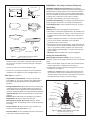
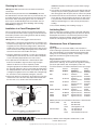
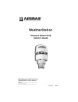
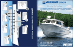
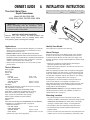
OWNER’S GUIDE
& INSTALLATION INSTRUCTIONS
Thru-Hull, Metal Stem
Depth Transducer
Record the information found on the cable tag for future reference.
PN:___________________Date___________Frequency________kHz
Models: B45, B46, B258, B260,
SS258, SS260, SS261, SS270W, SS505, SS560
Standard
Fairing
17-008-05 rev. 11
01/07
B45
IMPORTANT: Please read the instructions completely
before proceeding with the installation. These
instructions supersede any other instructions in your
instrument manual if they differ.
CAUTION: NEVER USE SOLVENTS!
Cleaners, fuel, paint, sealants, and other products may
contain strong solvents, such as acetone, which attack
many plastics greatly reducing their strength.
High-Performance
Fairing
Applications
Identify Your Model
• Bronze transducer recommended for fiberglass or wood hulls.
Never mount a bronze transducer in a metal hull, because
electrolytic corrosion will occur.
• Stainless steel transducer compatible with all hull materials.
Recommended for aluminum hulls to prevent electrolytic corrosion
provided the stainless steel transducer is isolated from the metal hull.
Caution: Installation requires using a fairing kit to isolate the
stainless steel transducer from a metal hull.
• Never install a metal transducer on a vessel with a positive
ground system.
The model name is printed on the cable tag.
Tools & Materials
Safety goggles
Dust mask
Electric drill
Drill bits:
Pilot hole
3mm or 1/8"
B45, B46, SS505
22mm or 7/8"
B260, SS260, SS261,
SS270W, SS560
33mm or 1-5/16"
B258, SS258
30mm or 1-3/16"
Sandpaper
Mild household detergent or weak solvent (such as alcohol)
File (installation in a metal hull)
Fairing (MANDATORY FOR SS261 AND SS560)
Angle finder or digital level (installation with a fairing)
Band saw or hand saw (installation with a fairing)
Rasp or power tool (installation with a fairing)
Marine sealant (suitable for below waterline)
Slip-joint pliers
Zip-ties
Water-based antifouling paint (MANDATORY IN SALT WATER)
Installation in a cored fiberglass hull: (see page 4)
Drill bit for hull interior:
B45, B46, SS505
35mm or 1-3/8"
B260, SS260, SS261,
SS270W, SS560
42mm or 1-5/8"
B258, SS258
40mm, 41mm, or 1-5/8"
Cylinder, wax, tape, and casting epoxy
About Fairings
Nearly all vessels have some deadrise angle at the mounting
location. If the transducer is mounted directly to the hull, the
sound beam will be tilted to the side at the same angle as the
deadrise. A fairing is strongly recommended if the deadrise angle
exceeds 10°.
• Orients the sound beam straight down by mounting the
transducer parallel to the water surface.
• Mounts the transducer deeper in the water for clean flow over
the transducer’s face.
Made of a high-impact polymer with an integrated cutting guide,
an Airmar fairing is safer and easier to cut with a band saw and
shape with hand tools than custom fairings. It can be shaped to
accommodate a deadrise angle of up to about 25°. (For fairing
part numbers, see “Replacement Parts” on page 4.)
A backing block is mounted inside the hull to provide a level
surface for the hull nut to seat against (see Figure 2). It is
fabricated matching the interior deadrise angle of the boat. After
cutting an Airmar fairing, use the remaining section with the
cutting guide for the backing block.
High-Performance Fairing has a long streamlined shape for
excellent performance above 15kn (18MPH). (To order see
“Replacement Parts” on page 4.)
Mounting Location
• The water flowing across the hull must be smooth with a
minimum of bubbles and turbulence (especially at high speeds).
Caution: DO NOT MOUNT near water intake or discharge
openings or behind strakes, fittings, or hull irregularities.
• The transducer must be continuously immersed in water.
• The transducer beam must be unobstructed by the keel or
propeller shaft(s).
• Choose a location away from interference caused by power and
radiation sources such as: the propeller(s) and shaft(s), other
Installation—No fairing or Standard Fairing only
pressure waves
1/3 aft
LWL
(Load Waterline Length)
150-300mm
(6-12")
displacement hull
WARNING: A High-Performance Fairing must be installed
following the Installation Instructions that come with the fairing. The
High-Performance Fairing requires an anti-rotation bolt. Failure to
install the anti-rotation bolt may result in the fairing rotating while
the boat is underway. The effect may be violent movement and loss
of steering. This could result in serious injury or death to
passengers and/or damage to the boat or other property.
Installation with NO fairing—If installing a transducer without a
fairing, disregard all references to a fairing and backing block.
Cored fiberglass hull—Follow separate instructions on page 4.
Hole Drilling
outboard and I/O
planing hulls
inboard
stepped hull
fin keel sailboat
full keel sailboat
Figure 1.
Best location for the transducer
Copyright © 2005 Airmar Technology Corp.
machinery, other echosounders, and other cables. The lower
the noise level, the higher the echosounder gain setting that
can be used.
• Choose a location with a minimum deadrise angle.
• Choose an accessible spot inside the vessel with adequate
headroom for the height of the stem and tightening the nut.
Boat Types (see Figure 1)
• Displacement hull powerboat—Locate 1/3 aft LWL and
150–300mm (6–12") off the centerline. The starboard side of
the hull where the propeller blades are moving downward is
preferred.
• Planing hull powerboat—Mount well aft near the centerline and
well inboard of the first set of lifting strakes to insure that it is in
contact with the water at high speeds. The starboard side of the
hull where the propeller blades are moving downward is preferred.
Outboard and I/O—Mount just forward and to the side of the
engine(s).
Inboard—Mount well ahead of the propeller(s) and shaft(s).
Stepped hull—Mount just ahead of the first step.
Boat capable of speeds above 25kn (29MPH)—Review
transducer location and operating results of similar boats before
proceeding.
• Fin keel sailboat—Mount to the side of the centerline and
forward of the fin keel 300–600mm (1–2').
• Full keel sailboat—Locate amidships and away from the keel
at the point of minimum deadrise angle.
2
Warning: Always wear safety goggles and a dust mask.
1. Drill a 3mm or 1/8" pilot hole perpendicular to the waterline from
inside the hull (see Figure 2). If there is a rib, strut or other hull
irregularity near the selected mounting location, drill from the
outside.
2. Using the appropriate size drill bit, cut a hole from outside the
hull. Be sure to hold the drill plumb, so the hole will be
perpendicular to the water surface.
3. Sand and clean the area around the hole, inside and outside, to
ensure that the marine sealant will adhere properly to the hull. If
there is any petroleum residue inside the hull, remove it with
either a mild household detergent or a weak solvent (alcohol)
before sanding.
Metal hull—Remove all burrs with a file and sandpaper.
Cutting the Standard Fairing
Warning: High-Performance Fairing—For your safety it is
mandatory to follow the Installation Instructions that come with the
fairing.
1. Measure the deadrise angle of the hull at the selected location
using an angle finder or a digital level (see Figure 2)
2. Tilt the band saw table to the measured angle and secure the
cutting fence (see Figure 3).
Caution: The ARROW always points forward toward the bow.
(A symmetrical fairing can be oriented either way.) Be sure to
orient the fairing on the band saw so the angle cut matches the
intended side of the hull and not the mirror image.
cable
Aft View
stem
hull nut
hull (metal)
backing block
slope of hull
isolation sleeve
deadrise
angle
fairing thickness
6–12mm (1/4–1/2")
parallel to
waterline
transducer
Standard Fairing
marine
sealant
Figure 2. Bedding and installing in a metal hull
(B45 with Standard Fairing shown)
Copyright © 2005, 2007 Airmar Technology Corp.
Installing
band saw
table
cutting
guide
deadrise
angle
fence
arrow end
for installation
on port side
Figure 3. Cutting a Standard Fairing
Copyright © 2005 Airmar Technology Corp.
3. Place the fairing on the table so the cutting guide rests against
the fence. The arrow will be pointing toward you for installation
on the port side and away from you for installation on the
starboard side of the boat (see Figures 3 and 4).
4. Adjust the cutting fence. The fairing must be between
6–12mm (1/4–1/2") at its thinnest dimension (see Figure 2).
Warning: Always wear safety goggles and a dust mask.
5. Recheck steps 1 through 4. Then cut the fairing.
6. Shape the fairing to the hull as precisely as possible with a rasp
or power tool.
7. Use the remaining section of the fairing for the backing block.
Bedding
Caution: Never pull, carry, or hold the transducer by the cable as
this may sever internal connections.
Caution: A stainless steel transducer/stem must be isolated from
a metal hull to prevent electrolytic corrosion.
Warning: SS261 or SS560—A fairing is mandatory for strength.
1. Remove the hull nut (see Figure 5).
2. Thread the transducer cable through the fairing (if used).
3. Apply a 2mm (1/16") thick layer of marine sealant around the
sides of the transducer that will contact the hull/fairing and up the
stem. The sealant must extend 6mm (1/4") higher than the
combined thickness of the hull, fairing and backing block (if
used), and the hull nut. This will ensure there is marine sealant in
the threads to seal the hull and hold the hull nut securely in place.
Also apply a 2mm (1/16") thick layer of marine sealant to the side
of the hull nut that will contact the hull.
Stainless steel transducer/stem in a metal hull—Slide the
isolation sleeve over the bedded transducer stem as far down as
possible (see Figure 2). Apply a 2mm (1/16") thick layer of the
marine sealant to the outside of the sleeving.
Standard Fairing—If a fairing is being used, seat the transducer
firmly in/against the fairing with a pushing twisting motion. Apply
a 2mm (1/16") thick layer of marine sealant to the surface of the
fairing that will contact the hull and the surface of the backing
block that will contact the hull (see Figure 5).
B45
B46
(symmetrical)
B258
SS258
Caution: Never strike the transducer.
1. From outside the hull, thread the cable through the mounting
hole. Then push the stem of the transducer through the hole
using a twisting motion to squeeze out excess sealant. Take care
to align the transducer with the blunt end facing the bow and the
long side parallel to the centerline of the boat (see Figure 4).
Standard Fairing—The arrow points forward toward the bow.
(A symmetrical fairing can be oriented either way.)
Stainless steel transducer/ stem in a metal hull—Be sure the
isolation sleeve is between the transducer stem and the hull (see
Figure 2). However, the top of the isolation sleeve must be below
the top of the hull nut or the backing block to prevent the sleeving
from interfering with tightening the hull nut.
2. From inside the hull, slide the backing block (if installing with a
fairing) and hull nut onto the cable. Seat the backing block
against the hull. Screw the hull nut in place and tighten it with
slip-joint pliers (see Figure 2 or 5).
Wood hull—Allow for the wood to swell.
Cored fiberglass hull—Do not over-tighten crushing the hull.
3. Remove any excess marine sealant on the outside of the hull/
fairing to ensure smooth water flow over the transducer.
Caution: If the transducer came with a connector, do not
remove it to ease cable routing. If the cable must be cut and
spliced, use Airmar’s splash-proof Junction Box No. 33-035 and
follow the instructions provided. Removing the water-proof
connector or cutting the cable except when using Airmar’s
junction box, will void the transducer warranty.
4. Route the cable to the instrument being careful not to tear the
cable jacket when passing it through the bulkhead(s) and other
parts of the boat. To reduce electrical interference, separate the
transducer cable from other electrical wiring and the engine.
Coil any excess cable and secure it in place with zip-ties to
prevent damage.
5. Refer to the instrument owner’s manual to connect the
transducer to the instrument.
cable
BOW ➤
stem
hull nut
backing
block
hull
fairing
transducer
marine
sealant
Figure 5. Bedding and installing (SS260 with Std. Fairing shown)
Copyright © 2005, 2007 Airmar Technology Corp.
B260
SS260, SS270W, SS560
Figure 4. Transducer and Standard Fairing orientation (blunt end toward bow)
SS505
BOW ➤
Copyright © 2005, 2007 Airmar Technology Corp.
3
Checking for Leaks
When the boat is placed in the water, immediately check the
thru-hull transducer for leaks. Note that very small leaks may not
be readily observed. Do not leave the boat in the water for more
than 3 hours before checking it again. If there is a small leak,
there may be considerable bilge water accumulation after 24
hours. If a leak is observed, repeat “Bedding” and “Installing”
immediately (see page 3).
Caution: Completely seal the hull to prevent water seepage
into the core.
5. Coat a hollow or solid cylinder of the correct diameter with wax
and tape it in place. Fill the gap between the cylinder and hull
with casting epoxy. After the epoxy has set, remove the cylinder.
6. Sand and clean the area around the hole, inside and outside, to
ensure that the sealant will adhere properly to the hull. If there
is any petroleum residue inside the hull, remove it with either
mild household detergent or a weak solvent (alcohol) before
sanding.
7. Proceed with “Bedding” and “Installing” on page 3.
Installation in a Cored Fiberglass Hull
Antifouling Paint
The core (wood or foam) must be cut and sealed carefully. The
core must be protected from water seepage, and the hull must be
reinforced to prevent it from crushing under the hull nut allowing
the transducer to become loose.
Surfaces exposed to salt water must be coated with antifouling
paint. Use water-based antifouling paint only. Never use ketonebased paint since ketones can attack many plastics possibly
damaging the transducer. Reapply antifouling paint every 6
months or at the beginning of each boating season.
Warning: DO NOT leave the boat in the water unchecked for
several days.
Warning: Always wear safety goggles and a dust mask.
1. Drill a 3mm or 1/8" pilot hole perpendicular to the waterline from
inside the hull (see Figure 6). If there is a rib, strut, or other hull
irregularity near the selected mounting location, drill from the
outside. If the hole is drilled in the wrong location, drill a second
hole in a better location. Apply masking tape to the outside of the
hull over the incorrect hole and fill it with epoxy.
2. Using the appropriate size drill bit, cut a hole from outside the
hull through the outer skin only. Be sure to hold the drill plumb,
so the hole will be perpendicular to the water surface.
3. The optimal interior hole diameter is affected by the hull’s
thickness and deadrise angle. It must be large enough in
diameter to allow the core to be completely sealed.
Using the appropriate size drill bit for the hull interior, cut through
the inner skin and most of the core from inside the hull keeping
the drill perpendicular to the hull. The core material can be very
soft. Apply only light pressure to the drill bit after cutting through
the inner skin to avoid accidentally cutting the outer skin.
4. Remove the plug of core material so the inside of the outer skin
and the inner core of the hull is fully exposed. Sand and clean
the inner skin, core, and the outer skin around the hole.
dimension equal to
the thickness of the
hull’s outer skin to
ensure adequate
clearance
Maintenance, Parts & Replacement
Cleaning
Aquatic growth can accumulate rapidly on the transducer’s
surface reducing its performance within weeks. Clean the surface
with a Scotch-Brite® scour pad and mild household detergent
taking care to avoid making scratches. If the fouling is severe,
lightly wet sand with fine grade wet/dry paper.
Replacement Parts
The information needed to order a replacement transducer is
printed on the cable tag. Do not remove this tag. When ordering,
specify the part number, date, and frequency in kHz. For
convenient reference, record this information on the top of page 1.
Model
B45
Hull Nut
02-031-3
B46
02-031-3
B258
02-222-03
SS258
02-539-01
B260
02-036-2
SS260, SS270W
02-036-03
SS261
SS505
SS560
02-036-03
02-111-01
03-169
inner skin
pour in
casting
epoxy
core
Fairing Type
Standard
High-Performance
Standard
High-Performance
Standard
High-Performance
Standard
High-Performance
Standard
High-Performance
Standard
High-Performance
High-Performance
High-Performance
High-Performance
Fairing
33-351-01
33-352-02
33-020
33-359-01
33-226-01
33-523-01
33-226-01
33-523-01
33-030
33-391-01
33-030
33-391-01
04-645-02
33-355-01
33-466-01
Obtain parts from your instrument manufacturer or marine dealer.
hull
outer skin
solid or hollow
cylinder
Gemeco (USA)
Airmar Europe
Figure 6. Preparing a cored fiberglass hull
Copyright © 2005 Airmar Technology Corp.
AIRMAR
Tel:
Fax:
email:
Tel:
Fax:
email:
843.394.3565
843.394.3736
[email protected]
+45.45.81.04.18
+45.45.81.04.93
[email protected]
®
35 Meadowbrook Drive, Milford, New Hampshire 03055-4613, USA
TECHNOLOGY CORPORATION
www.airmar.com
4
■
Copyright © 2003, 2005, 2007 Airmar Technology Corp. All rights reserved.