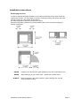
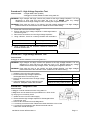
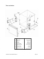
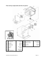
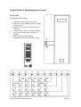
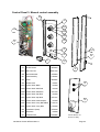
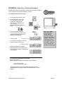
1
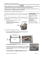
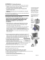
Mealstream 400
SERIES
SERVICE
MANUAL
Part No. 32Z3769 Issue No. 1
For all 400 Series models manufactured from February 2009
SERVICE MANUAL
Merrychef
CAUTION MICROWAVE EMISSIONS
DO NOT BECOME EXPOSED TO EMISSIONS FROM THE MICROWAVE
GENERATOR OR PARTS CONDUCTING MICROWAVE ENERGY
400 Series Ovens 32Z3769 Issue 1
Page 1
Table of Contents
Safety Code ...................................................................................................3
Product Specifications ...................................................................................4
Installation Instructions ..................................................................................5
Electrical Installation ......................................................................................6
Error Codes and Diagnostics.........................................................................7
Main Features ................................................................................................8
Electronic Controls.........................................................................................9
Power Output Testing to EN 60335-2-90.....................................................10
Power Transformer Test ..............................................................................10
High Voltage Capacitor Test........................................................................11
High Voltage Rectifier Test ..........................................................................11
Magnetron Test............................................................................................11
Door Interlock Operation........................................................................ 12-14
Casework .....................................................................................................15
Door Mechanism..........................................................................................16
Oven Cavity Components & Hot Air System ...............................................17
Oven Door Assembly...................................................................................18
Door Interlock RHS, Magnetron & Stirrer motor ..........................................19
Principal components LHS & Rear View .....................................................20
Principal components RHS 1: Models _EE5, _XE5 [CD2] ..........................21
Principal components RHS 2: Models _EE5, _XE5 [CD2] ..........................22
Principal components RHS 3: Models _XX5, _XX52...................................23
Input Wiring, Filters and Fuses 1 .................................................................24
Input Wiring, Filters and Fuses 2 .................................................................25
Control Panel 1: Electronic Controls............................................................26
Control Panel 2: Membrane Panel circuit ....................................................27
Control Panel 3: Manual Control assembly .................................................28
Part No. Identification ........................................................................... 29-30
Appendix 1 MenuKey Download Procedure ................................................31
Appendix 2 Cleaning Procedure ..................................................................32
Recommended Parts List (Spares)........................................................34334
Circuit Diagrams .................................................................................... 35-38
For Service contact:
Merrychef Limited,
Station Road West,
Ash Vale, Aldershot
Hampshire GU12 5XA
United Kingdom
Tel: +44 (0)1252 371000 Fax: +44 (0)1252 371007
Internet address: http://www.merrychef.com
E-mail: [email protected] or [email protected]
Merrychef and MenuKey™ are registered Trademarks of Merrychef Ltd.
400 Series Ovens 32Z3769 Issue 1
Page 2
SAFETY CODE
This manual is designed to assist engineers who have been on a recognised product familiarisation
and training course run by Merrychef Limited. It has been prepared to offer technical guidance for the
Merrychef Mealstream 400 range of Combination Microwave Ovens.
Please remember that it is wiser not to attempt a service task if you are unsure of being able to
complete it competently, quickly, and above all safely.
To avoid injury to yourself, and to protect the appliance from possible damage, please follow this
Safety Code when servicing these ovens.
Before attempting to repair the oven, check it for microwave leakage.
Check that the oven is not emitting microwaves, even when supposedly not
in operation.
Check that the oven is not operating continuously, whether the display
indicates cooking or not.
Always discharge the HT capacitors before working on the oven using a
suitably insulated 10 MΩ Resistor
Before removing the rear cover from the oven ensure you do the following:
•
•
Switch off the mains supply and remove the plug from the wall socket.
or
If the oven is hard wired, ensure that the power is turned off at the isolator switch.
Note: the On/Off switch on the oven is not adequate protection against electric shock, as it does
not isolate all of the internal wiring from the Electrical Supply.
Upon completion of a service on a Mealstream 401/403 oven, or before reconnecting the appliance
to the mains supply for testing, check all of the following points:
•
•
•
•
•
•
•
•
All internal electrical connections are correct.
All wiring insulation is correct and is not touching a sharp edge.
All Earth connections are electrically and mechanically secure.
All four door safety interlocks are secure and mechanically sound.
The door operation is smooth, and the arms run freely in the slots.
The door activates all four of the door interlock switches in the correct order.
All fuse-holder safety covers are correctly fitted.
The temperature sensor is correctly connected to the Power PCB.
Before finishing the service call, recheck the following points:
•
•
•
•
•
All of the electronics are functioning correctly, and all of the touch pads are working.
The turntable is rotating correctly.
The power output of the oven is correct (see pages 12 & 13 ).
Microwave emission is below permissible limit - 5 mW/cm² (see BS EN 60335-2-90).
Oven has correct 50mm air gap all round and 150mm above.
Air flow should not be restricted.
400 Series Ovens 32Z3769 Issue 1
Page 3
Product specifications: Mealstream 401 & 403 models
ELECTRONIC CONTROLS: ( EC401 & EC403 models )
Model No.: 1003 + Voltage + Frequency + Current + Controls
+ Phase + MenuKey + Catalytic converter
For example:
Model
prefix
1003
100345XE52MK
230-240V, 50Hz, 30A, Series 5 Controls, Twin Phase, MenuKey
Voltage
Frequency
Current
2 = 220-230V a.c. 5 = 50 Hz EE = 13A
4 = 230-240V a.c. 6 = 60 Hz
XE = 30A
Control Supply MenuKey Catalytic
converter*
Type
Phase
5=
Series 5
controls
2=
Twin
Phase
MK
C
XX = 30A
* A Catalytic converter is fitted to Mealstream 403 models only
MANUAL CONTROLS ( CD & XD models )
Model No.: 1003 + Voltage + Frequency + Current
Model prefix
1003
Voltage
Frequency
2 = 220-230V a.c.
4 = 230-240V a.c.
Power
Requirements
5 = 50 Hz
6 = 60 Hz
Current
CD2 = 13amp
XD2 = 30amp
See RATING PLATE on rear of oven
Power Output
(IEC 705)
Microwave 100%
Convection
Combination
700W
3000W
700W
700W
1000W
(_EE, _XE)
(_XX5 )
+ 1500W ( _EE )
+ 3000W ( _XE )
+ 3000W ( _XX5 )
External
Dimensions
Height
Width
Depth
530 mm (Plus 150 mm minimum clearance above)
550 mm (Plus 50 mm minimum clearance each side)
575 mm (Plus 50 mm clearance behind)
Internal
Dimensions
Height
Width
Depth
Turntable
Capacity
315 mm
330 mm
330 mm
300 mm Diameter
34.3 litres
Weight
Nett
Gross packed
All models except XX5 45kg,
All models except XX5 58kg,
Construction
Cavity
Casework
Stainless Steel
304 Stainless Steel
Anodised Aluminium Extrusions
Settings
Microwave
Temperature
Timer
100%,75%,50%,25%, Convection only
Off, 175°C, 200°C, 225°C, 250°C, 275°C
Up to 30 minutes
XX5 55kg
XX5 68kg
Up to 3 cooking stages of up to 30 minutes each
(Programmed)
400 Series Ovens 32Z3769 Issue 1
Page 4
Installation instructions
Positioning the Oven
In order to maintain adequate ventilation for air intake and exhaust, and to allow access for
cleaning the air filters, you must allow a minimum of 50mm(2 inches) clearance at the sides
and rear of the oven, and at least 150mm above.
Air intake temperature should not exceed 35°C (95°F).
Excessive temperature will lead to reduced operating duty cycle or premature ageing of
internal components.
NEVER
Install an oven above fryers, grills, griddles or any other major heat source.
NEVER
Stack machines on top of each other - always use a double stand.
ALWAYS
Place containers in the cavity carefully - impact damage may chip the
vitreous enamel coating.
400 Series Ovens 32Z3769 Issue 1
Page 5
Electrical installation:
WARNING: This appliance must be earthed.
Failure to do so may result in electric shock and death
All models ( 30A ) must be connected to a separate electrical supply rated at
WARNING 30 Amps by a qualified and approved electrician. A suitable 30 amp rated
isolating switch with a 3mm contact gap on both poles should be fitted for each
oven installed.
Establishments with standard ( Type ‘B’ ) circuit breakers are sensitive to ‘surges’ which occur
on switching on freezers, refrigerators and other catering equipment, including microwave
ovens. Because of this, we strongly recommend that a separate Type ‘C’ circuit breaker
( designed specifically for this type of equipment ) must be fitted. An individual, suitably rated
circuit breaker should be fitted for each oven installed.
Models 1003__EE5, 1003__CD2
The power outlet used must be individually fused. It
is essential that the socket is properly installed and
earthed. It should be fed from a circuit which is
suitable for high power electrical appliances and it is
important that this circuit is not overloaded.
Where an approved and fitted moulded plug is
supplied we strongly recommend that this plug is
never removed.
However certain establishments may require a
different plug to be fitted. In this case, the wiring
instructions shown should be observed.
Diagram 1
Models 1003__XE5, 1003__XD, 1003__XX5
When supplied, single phase models are fitted with a
Blue 32Amp Plug approved to BS4343. Wiring cable
colours as shown in Diagram 1
The Circuit Breaker should be rated at 45A (TypeC).
TWIN PHASE
Models 1003__XE52, 1003__XX52
The Mealstream 401 oven Twin Phase models
should be connected as shown in Diagram 2.
The Circuit Breaker should be rated at 20A per phase
(TypeC).
Simplified loading Diagram
400 Series Ovens 32Z3769 Issue 1
Diagram 2
Page 6
Error codes and diagnostics
Electronic Control Models
The control panel will identify some of the most common problems by flashing an error
message code in the time display window.
Possible Cause
Service
1
Door not fully shut
Close door fully.
2
Possible electrical fault
Check Microswitch Door Circuit
Check Microswitch Connection to PCB
Check Ribbon Cable
Check Relay PCB & Logic PCB
1
2
3
4
No time has been set
Invalid time has been set
Invalid program has been set
Number pad failure
Error Message
5
Set a time
Set a valid time
Use call-back to check program
(Menukey: no key downloaded)
Membrane key short circuit
Memory Failure running a Program Re-Program Pad,
if fault repeats replace Logic PCB
1
Oven is not at correct temperature
to start program
Allow oven to reach correct
Programmed temperature
1
MenuKey removed before the
download is complete
or the process has been
interrupted
Switch oven off and begin the MenuKey
download again
1
Magnetron overheated
Air inlet on rear of machine being obstructed.
High air inlet temperature.
Slow running cooling fan, jammed turntable or
broken gearbox
(cooling fan also drives turntable _XE5 models)
Faulty magnetron overheat ‘stat or associated
wiring.
1
Jumper installed incorrectly on
PCB logic board
Check Jumper position
1
2
Magnetron has overheated but
has now recovered
Internal diagnostic fault
Check that magnetron cooling fan and turntable
are working correctly
Check installation, air inlet temperature and air
filters
1
Oven control area is overheating
Check air filters.
Check axial fan
Check installation for hot air intake
EPS= External Program System
[Service]
[Air Filter blocked]
Error Light Operation
The “Air Filter Blocked” light and “Service” light are triggered by the internal circuitry. If the magnetron
overheats, the error code “E:7” or “E:8” is displayed on the front panel, and both the “Air Filter Blocked”
and the “Service” indicators will light. Once the magnetron has cooled sufficiently to allow the oven to
restart, the “Service” light will remain illuminated until the oven is turned off.
This fault may have been triggered by one of the following causes:
- Air inlet on rear of machine being obstructed.
- High air inlet temperature.
- Slow running cooling fan, jammed turntable or broken gearbox
(note: cooling fan also drives turntable on EE5, CD2 and XE5 models).
- Faulty magnetron overheat ‘stat or associated wiring.
Note that the customer may not have noticed that the oven displayed “E:7” or “E:8”, and so the
reported fault may be misleading.
400 Series Ovens 32Z3769 Issue 1
Page 7
Main features
b
d
c
e
p
g
f
h
q
n
j
l
rear view of Oven
k
m
b VENTS
c TRAY HANDLE RESTS
There is one on each side of the oven for
convenient storage of the tray handle.
d BAFFLE PLATE
Forms the inside rear of the oven and covers the
hot air circulation fan. Removable for cleaning by
unscrewing the four wing nuts which hold it in
place. This must be cleaned on a regular basis,
and kept free of debris.
CATALYTIC CONVERTOR
Allows extraction free cooking. Should be
removed regularly for cleaning. ( Do not spray/
put caustic cleaner directly into the catalytic
converter as this will cause permanent damage )
e RUNNERS
These mounted on each side of the oven cavity
to support the rectangular racks or oven trays,
and are for use in CONVECTION MODE ONLY.
f HOT AIR FAN
Situated behind the baffle plate, and circulates
the hot air through the baffle plate, over the
heating element, and around the edge of the
baffle plate back into the cavity.
h TURNTABLE TRAY
The vitreous enamelled turntable tray fits onto the
turntable disc in the bottom of the oven cavity,
and rotates during cooking to ensure an even
distribution of microwave energy so that the food
is cooked evenly.
j RATING PLATE
The rating plate is situated on the rear of the
oven, and states the Model, Serial Number,
Electrical Ratings and Manufacturers Tel no.
k DOOR
The door consists of a thermally insulated inner
section, and an additional air gap provided by a
twin skinned door front to lower the surface
temperature.
l ON/OFF SWITCH
This is used to turn the oven On or Off.
IT DOES NOT ISOLATE INTERNAL WIRING
FROM THE ELECTRICAL SUPPLY.
n ELECTRICAL SUPPLY LEAD
p AIR FILTER
Main intake for cooling air for internal
components. Must be clear of obstructions.
q MenuKey
g OVEN CAVITY
The oven cavity is stainless steel. It must be kept
clean See CLEANING.
400 Series Ovens 32Z3769 Issue 1
Page 8
Electronic controls:
a
Stage LED's
b
Service Indicator
a
c
Air Filter Block Indicator
b
e
Program Display
c
f
Temperature Set Pads
g
Time / Program Number Pads
h
Cancel/ Callback Pad
i
Program Pad
j
Convection Pad
k
Microwave power Pads
l
On/Off switch
e
m
f
MenuKey socket
g
i
h
j
k
l
400 Series Ovens 32Z3769 Issue 1
m
Page 9
Procedure B - Simplified Power Output Test for Field Service Use
You will need:
A thermometer capable of reading to ±0.1°C.
A Polypropylene tray approximately 200 mm x 200 mm.
A measuring jug.
A calculator.
Water which is at a temperature of 10°C ± 2°C.
1
2
3
4
5
6
7
8
Procedure A - Power Output Test In accordance
with BS EN 60335-2-90 is not used in the field please
Engineers Procedure B.
Measure 1 litre of cold water into the tray using the measuring jug.
Measure the water temperature, and record it as T[s].
Place the tray on the turntable in the oven and close the door.
Turn the oven on.
Set the timer to 1:02. ( For Manual controls use a stopwatch set to 1 minute 2 seconds )
Press the “100%” power pad.
When the oven bleeps, open the door and remove the tray.
Stir the water thoroughly, and measure its temperature. Record this as T[e].
Calculation:
1
2
T[r] = T[e] - T[s].
Power = 70 x T[r]. Power is in Watts.
The power given by the above test should be within ±10% of the rated power.
Procedure C - Power Transformer Test
You will need:
A Digital Multi-meter (D.M.M.)
A Megger or similar resistance meter using 500V d.c.
1 Isolate the oven from the mains supply.
WARNING: High voltages and large currents are present at the secondary winding and filament
winding of the Power Transformer. It is very dangerous to work near this part when the
oven is on. NEVER make any voltage measurements at the High Voltage circuits,
including the magnetron filament.
WARNING: Even when the oven is not cooking, the Power Transformer has High Voltages present
because of the Soft Start circuit. Isolate the oven before testing.
2
3
4
Ensure that the High Voltage Capacitor is discharged before commencing work.
Remove all connections from the Power Transformer.
Using a D.M.M., check the continuity of the windings. Results should be as follows:
a
Mains winding between tags
b
High Voltage winding
c
Filament winding
between terminals
5
Using a Megger, test the insulation resistance between:
Approx. 1.3 Ω
c
Approx. 50-100 Ω
b
Less than 1 Ω
Primary winding and chassis
Pass if over 10 MΩ
Filament winding and chassis
Pass if over 10 MΩ
a
One end of the High Voltage winding is connected to the
chassis, so this is not tested.
400 Series Ovens 32Z3769 Issue 1
Page 10
Procedure D - High Voltage Capacitor Test
You will need:
A Digital Multi-meter (D.M.M.)
A Megger or similar resistance meter using 500V d.c.
WARNING: High voltages and large currents are present at the High Voltage Capacitor. It is very
dangerous to work near this part when the oven is on. NEVER make any voltage
measurements at the High Voltage circuits, including the magnetron filament .
WARNING: Even when the oven is not cooking, the High Voltage Capacitor has High Voltages
present because of the Soft Start circuit. Isolate the oven before testing.
1. Isolate the oven from the mains supply.
2. Ensure that the High Voltage Capacitor is discharged before
commencing work.
3. Remove all connections from the High Voltage Capacitor.
4. Using a D.M.M., check for continuity between the terminals &
Between Terminals
Pass if approximately 10 MΩ
Between Terminals and Case
Pass if open circuit
5. Using a Megger, test the insulation resistance between the
terminals and the case.
Between Terminals and Case
Pass if over 100 MΩ
Procedure E - High Voltage Rectifier Test
You will need:
A Megger or similar resistance meter using 500V d.c.
WARNING: High voltages and large currents are present at the High Voltage Rectifier. It is very
dangerous to work near this part when the oven is on. NEVER make any voltage
measurements at the High Voltage circuits, including the magnetron filament .
WARNING: Even when the oven is not cooking, the High Voltage Rectifier has High Voltages
present because of the Soft Start circuit. Isolate the oven before testing.
1. Isolate the oven from the mains supply.
2. Ensure that the High Voltage Capacitor is
discharged before commencing work.
3. Remove all connections from the High Voltage
Rectifier.
4. Using the Megger, test for continuity in both
directions. Compare results with the table.
Open Circuit both ways
FAIL
Conducts one way only
PASS
Short Circuit both ways
FAIL
Conducts one way, leaks the other
FAIL
Procedure F - Magnetron Test
You will need:
A Megger or similar resistance meter using 500V d.c.
A Magnetron can be tested for an open filament or a short circuit
by carrying out a continuity check.
1. Isolate the oven from the mains supply.
2. Ensure that the High Voltage Capacitor is discharged before
commencing work.
3. Remove all connections from the Magnetron.
4. A continuity check across the Filament terminals should be 1ohm or less
5. A continuity check between each filament terminal and the
metal outer should read open.
400 Series Ovens 32Z3769 Issue 1
Page 11
Door interlock operation
The door on the oven is monitored by five microswitches. Three of these are used in the
conventional “Primary, Secondary and Monitor” switch arrangement shown below, while the fourth
is a low-voltage switch linked directly to the control circuitry and the fifth switches the power to the
convection motor.The switches operate as follows:
Door open position
LHS
SW3 Secondary
SW2 Primary
Fused
Live
SW1 Monitor
Output
Neutral
RHS
SW4
Live
Convection Fan
Neutral
SW5
Control PCB
SW2 Primary Interlock— located on the left hand side of the oven. Directly disconnects
the supply to the microwave generating circuit and thereby cuts off the microwave emissions
from the oven when the door is opened.
SW1 Monitored switch—located on the same assembly as the primary. The Monitor
switch will produce a short circuit across the mains supply if the Primary interlock switch is
faulty, thus blowing the microwave fuse and rendering the oven inoperative.
SW3 The Secondary interlock—located on the left hand side of the oven and like the
primary switch will cut off the microwave emission and will do so even if the primary and
monitored interlock have failed open circuit.
Note: If operation of the Monitor switch has caused the Microwave Fuse to blow, the
Primary and Monitor microswitches must be changed, as they may have been
damaged by the high short-circuit currents involved.
SW4 Convection fan switch—located on the same bracket as the control switch.
This switch is wired in series with the convection motor supply and will disconnect when
the door is opened.
SW5 Control switch—located on the top right behind the display connects to the
logic control PCB on a black and white twisted pair of wires. It is this signal that is used by
the control circuit to determine the door position. A closed contact indicates a closed door.
400 Series Ovens 32Z3769 Issue 1
Page 12
Procedure for Door Interlock and test:
WARNING
Before adjusting the microswitch assemblies ensure that the oven has been
isolated from the electrical supply and discharge the HT Capacitors.
Please note the terminals on the microswitches remain live when the oven is
switched off, so complete isolation is essential.
Tools Required: Door Spacer Kit P10H0129, Multimeter
The purpose of this procedure is to set the interlock so that when the
door is opened more than 3mm the Oven microwave circuit is switched
OFF.
The door closed position [Microwave circuit ON] is actually set with a
1mm opening to allow for heat expansion when the oven is operating at
full temperature.
1
The three interlock Microswitches are located
on the LHS of the oven.
Release the 2 screws retaining each
microswitch assembly just enough to allow
the assembly to move.
SW1 & SW2
Five Microswitches:
SW1, SW2 & SW3 door
interlock Microswitches are
located on the LHS of the
oven.
SW4 & SW5 are located on
the RHS of oven behind the
control panel.
SW4 switches off the
convection fan
SW5 sends a ‘door open‘
signal to the Control Board
SW3
2
Position the door open with a 3mm gap:
Place the two 3mm Spacers over the door seal at the top of the
door on each side at the corner and carefully close the door
ensuring the spacer is on the door seal.
3mm Spacers
Door
Seal
Door
To set Microswitches SW1 & SW2 and SW3 to OPEN [OFF] at a
door opening with a 3mm gap:
Slide forward Microswitch assembly to set SW2 to just click CLOSED
and then allow the assembly to move slightly approx. 0.05– 0.10 Inch
(1-2mm) to just allow the switch to return to the OPEN position and
tighten both screws.
Repeat for SW3 rotating clockwise to CLOSED until it just opens then
anti-clockwise slightly to the OPEN position and tighten screws.
400 Series Ovens 32Z3769 Issue 1
Page 13
3
Remove the 3mm spacers and open and close
the door 2 or 3 times to allow the parts to work
together.
Set a Multimeter Resistance [ Ω ] and connect
the meter to the microswitch terminals 37 &
29.
Replace the 3mm spacers on the door and over
the corners of the seal as before.
3mm Spacers
Open Circuit
Door
Seal
Door
The meter should now read open circuit,
if not repeat steps 1 & 2 adjusting the switch assemblies slightly
upwards, ensuring the Microswitches are in the OPEN [OFF]
position.
4
To confirm the oven operates at a 1mm door open position.
Replace the 3mm spacers with the two 1mm Spacers.
1mm Spacers
Door
Seal
0.1
Door
Check that microswitches SW1,SW2 and SW3 are in the CLOSED [ON]
position and the Multimeter reads a minimal resistance.
If the meter reads Open Circuit, remove the 1mm spacers and repeat steps 14 moving the switch assemblies very slightly further down.
This procedure may need to be repeated several times to achieve a
satisfactory arrangement.
400 Series Ovens 32Z3769 Issue 1
Page 14
Principal components: casework
4
3
2
6
1
7
104
2
96
8
12
9
105
11
140
MC3134
9
Handle Hanger
RMC6773
11
Front Lower Panel
MC3047
MC3120MC
12
Lower Trim
MC3122
RMC6759EMC
96
PCB Retainer
40H0084
MC3769MC
104
Side Trim LH
MC3789MC
105
Side Trim RH
MC3121
140
Rubber Base seal long
Rubber Base seal short
40H0259
40H0260
1
Side Panel (L/H)
2
Ferrite
3
Upper Trim
4
Top Plate
6
Rear Panel
7
Air Filter
MC3155
8
Side Panel (R/H)
MC3145
400 Series Ovens 32Z3769 Issue 1
RCK6319
Page 15
Door mechanism
13
Door Stay (R/H)
14
Hinge Body
15
Hook (A)
RMC66171
16
Hook (B)
RMC66172
17
Door Spring (B)
18
Hinge Body (L/H)
19
Door Spring (A)
MC3067
20
Door Stay (L/H)
MC3046
22
Solid Door Assy Silver
400 Series Ovens 32Z3769 Issue 1
MC3040
MC30121X02
MC3068X01
MC30122X01
MC3230MCX02
Page 16
Oven cavity components and hot air system
Catalytic Converter
137
136A
135
25
23
Turntable Disc
RMC7340X01
34
Motor Bracket
RMC7307X01
24
Baffle Plate Bolt
CP30326
37
Convection Motor
MC3730MOD
25
Baffle Plate
MC3018
135
Catalytic Converter
26
Fan Fixing Cap
RCK7617
27
Convection Fan
MC3111
30
Oven Body
31
Gearbox
32
Shaft
33
Motor Cooling Fan
136A Vent Plate
137
Thumb nut
31Z1245
40H0236
31Z4031
MC3750MC
MC3216
RMC7391X01
400 Series Ovens 32Z3769 Issue 1
RMC7310
Page 17
Oven door assembly
49
22
Solid Door Assy.
38
Door Handle Silver
40
Door Cover Outer
40H0080
41
Inner Panel
40H0081
42
Door Reinforcement
43
Door Frame (B)
MC3055
44
Insulation Wrap
32Z0001
46
Door Base Silver
MC3031X05
47
Door Cover
MC3064X01
48
Plate - Door Switch RHS
MC3056
49
Plate - Door Switch LHS
MC0562MC
52
Packing (B)
MC3065
53
Door Rear Plate
MC3229
400 Series Ovens 32Z3769 Issue 1
MC3230MCX02
RBR1285048
RMC70722
Page 18
Door Interlock RHS, Magnetron & Stirrer Motor
129
133
54 Door Switch Bracket
40H0023
61
Foam Tape
31Z0042
55 Microswitch SW4
30Z0240
63
Magnetron
30Z1349
56 Microswitch SW5
30Z0240
64
Magnetron Thermal trip
30Z0088
59 Microswitch Insulator
31Z0115
129
Turntable Motor
11H0110
60 Outlet Duct
MC3037
400 Series Ovens 32Z3769 Issue 1
Page 19
Principal Components LHS & Rear view:
Microswitches
138
139
57
117
57
Secondary Microswitch SW3
30Z0240
117
Axial fan
11H0075
138
Primary Microswitch SW2
30Z1396
139
Monitor Microswitch SW1
30Z1395
142
55
56
74
73
143
37
37
Hot Air Motor
55
Microswitch SW4
30Z0240
56
Microswitch SW5
30Z0240
69
Thermal cut-out switch
30Z1024
73
Heater Element 240V
40H0009
74
Temperature Sensor
30Z1419
142
Exhaust steam pipe
143
MC3730MOD
Note:
1. The 270Ω Resistor is required to
drop the supply voltage to the
Convection Fan Motor to 208V.
MC3773
1
Motor Resistor Assembly
400 Series Ovens 32Z3769 Issue 1
11H0122
Page 20
69
Principal Components RHS 1 : Models _ EE5, _ XE5, [CD2]
71
70
60
90
128
76
76A
117
60
Outlet Duct
70
Bridge Rectifier
71
No. 8 Screw
31Z3107
76
HT Capacitor 0.75uF 2500V
30Z1329
76A Capacitor Clip
MC3037
341520
30Z1261
90
Transformer 208-240 50Hz
30Z1233
117
Axial Fan
11H0075
128
Cooling Fan 240V 50Hz
11H0091
400 Series Ovens 32Z3769 Issue 1
Page 21
Principle components RHS 2: _ EE5, _ XE5
75
HV Diode Assembly
76
HT Capacitor 0.75uF 2500V
30Z1329
88
HT Transformer Top Bracket
MC3127
89
HV Lead Assembly, Ferrite
11H0025
90
Transformer 208-240V 50Hz
30Z1233
91
HT Transformer Bottom Bracket
40H0070
92
Capacitor Band
93
Filter Bracket
40H0065
94
HT Transformer Support Bracket
MC3024
400 Series Ovens 32Z3769 Issue 1
11H0010
RMC7215
Page 22
Principle components RHS 3: _ XX5, _XX52
140
130
128
90
117
90
76
76A
76
HT Capacitor 0.75uF 2500V
76A Capacitor Clip
30Z1329
30Z1261
90
Transformer 208-240 60Hz
30Z1233
117
Axial Fan
11H0075
128
Cooling Fan 208V 50Hz
30Z1128
130
Diode Board
11H0058
140
Potentiometer
1
11H0058
Note:
1. The Potentiometer adjusts the cavity set point temperature
400 Series Ovens 32Z3769 Issue 1
Page 23
Input wiring, filters and fuses 1
Model 1003__XE5, XD5
Model 1003__EE5, CD2
Green / Yellow
Green / Yellow
Blue
Blue
Brown
111
112
112a
115
111
116
Model:
UK
113
Cable
Assembly
111
Mains Input Block
31Z0328
113
_ EE, _CD2
10H0012
112
Cable Gland
31Z1070
113
_XE5 [Single phase]
10H0011
112A Cable Gland Nut
115
XE5 Input Cable Assembly
116
Strain Relief Grommet
31Z1082
302030
Europe
113
_XE5 [Single phase]
10H0064
31Z1036
82
78
79
81
77
80
79
81
77 Microwave Mains Filter 16A
30Z1340
78 Heater Mains Filter 16A
30Z1340
79 Fuse Cover
20Z1080
80 Fuse 10A HRC
30Z0217
81 Fuse Holder 1”
30Z0231
82 Fuse 13A
30Z0456
400 Series Ovens 32Z3769 Issue 1
Page 24
Input wiring, filters and fuses 2
Model RMC1003__XX5, XX52
Green / Yellow
Green / Yellow
Blue
Blue
Brown
L2
L1
111
112
112a
115
111
Model:
UK
115
Cable
Assembly
111
Mains Input Block
31Z0328
115
_ XX5 [Single phase]
10H0046
112
Cable Gland
31Z1070
115
_XX52 [Twin phase]
10H0039
112A Cable Gland Nut
31Z1082
Europe
113
Input Cable Assembly
31Z0220
115
_XE5 [Single phase]
10H0065
116
Strain Relief Grommet
31Z1036
115
_XX52 [Twin phase]
10H0063
78
77
82
81
80
81
77 Microwave Mains Filter 16A
30Z1340
78 Heater Mains Filter 16A
30Z1340
80 Fuse 10A HRC
30Z0217
81 Fuse Holder 1”
30Z0231
82 Fuse 13A
30Z0456
400 Series Ovens 32Z3769 Issue 1
Page 25
Control Panel 1: Electronic controls assembly
100
102
110
99
101
98
107
95
108
103
107
109
110
97
98
131
97
95
95
Membrane Assy
See table
97
On/Off Switch
30Z0503
Model
98
Logic Assy.
See table
EE5, XE5, XX5
11H0060
99
Support Shield
40H0075
XX5 Starbucks
11H0024
100 M3 x 5 Screw
31Z3106
EE5, XE5, XX5
Menukey
11H0067
101 No. 4 x 3/8” Screw
31Z3112
102 220R 50W Resistor
30Z0235
Membrane Assy
98
103
103 Relay Assy
See table
Model
Logic PCB
Relay PCB
107 PCB Stand-off
31Z7010
EE5,
11H0066
11C0286
108 15 Way Ribbon Connector
11Z0298
CD2, XD2
N/A
11H0027
309610
XE5, XX5
11H0066
11H0077
109 Single 0.25” Blade Tag Connector
110 M3 Nylon Support
31Z0206
131 Menukey Assembly
10H0081
400 Series Ovens 32Z3769 Issue 1
Page 26
Control Panel 2: Membrane panel circuit
You will need:
A Digital Multi-meter (D.M.M.)
1. Isolate the oven from the mains supply.
2. Remove the Logic Assembly from the Control
Panel Housing.
3. Unplug the membrane “tail” from the Logic
PCB Assy.
4. Using a D.M.M., check for continuity between
the correct terminals when the pads are
pressed.
5. When the panel has been tested,
re-assemble and re-test the control housing.
525°
400°
480°
400 Series Ovens 32Z3769 Issue 1
440°
350°
Page 27
Control Panel 3: Manual control assembly
96
123
124A
121
124B
124C
124D
122
125
105A
126
97
123
96
PCB Retainer LH
40H0084
97
On/Off Switch
30Z0503
105A Side Trim RH
MC31212
106
M5 Flat Washer
31Z5004
121
PCB Assembly
11H0027
122
Timer
30Z0991
123
Amber Neon
316031
124A Control Knob Black
313020
124B Control Knob Skirt Red
313160
124B Control Knob Skirt Blue
31Z1216
124C Control Knob Cap Red
313220
124C Control Knob Cap Blue
31Z1217
124D Control Knob Shaft Adaptor
11C0173
124E Control Knob Assy Blue
11C0406
Pushbutton (Start)
126
Red Neon
127
Potentiometer
400 Series Ovens 32Z3769 Issue 1
96
127
122
313030
124E Control Knob Assy Black/Red
125
106
31Z0349
316030
40C0892
Control Board not
shown for clarity
Page 28
Part number identification chart 1
1
SIDE PANEL (L/H)
MC3134
41
INNER INSULATION PANEL
2
FERRITE
3
UPPER TRIM
4
TOP PLATE
6
REAR PANEL
7
RMC6773
42
DOOR REINFORCEMENT
MC3120MC
43
DOOR FRAME (B)
MC3055
RMC6759EMC
44
INSULATION WRAP
32Z0001
MC3769MC
46
DOOR BASE SILVER
MC3031X05
AIR FILTER
MC3155
47
DOOR COVER
MC3064X01
8
SIDE PANEL (R/H)
MC3145
48
PLATE - DOOR SWITCH RHS
MC3056
9
HANDLE HANGER
RCK6319
49
PLATE - DOOR SWITCH LHS
MC0562MC
11
FRONT LOWER PANEL
MC3047
52
PACKING (B)
MC3065
12
LOWER TRIM
MC3122
53
DOOR REAR PLATE
MC3229
13
DOOR STAY (R/H)
MC3040
54
DOOR SWITCH BRACKET
40H0023
14
HINGE BODY
15
HOOK (A)
RMC66171
CONVECTION MOTOR
MICROSWITCH SW4
30Z0240
16
HOOK (B)
RMC66172
56
30Z0240
17
DOOR SPRING (B)
MC3068X01
LOW VOLTAGE
MICROSWITCH SW5
18
HINGE BODY (L/H)
MC30122X01
57
SECONDARY MICROSWITCH SW3
30Z0240
19
DOOR SPRING (A)
MC3067
59
MICROSWITCH INSULATOR
31Z0115
20
DOOR STAY (L/H)
MC3046
60
OUTLET DUCT
MC3037
22
SOLID DOOR ASSY
61
FOAM TAPE
31Z0042
23
TURNTABLE DISC
63
MAGNETRON
30Z1349
24
BAFFLE PLATE BOLT
64
MAGNETRON THERMAL TRIP
30Z0088
25
BAFFLE PLATE
69
THERMAL CUT OUT SWITCH
30Z1031
26
FAN FIXING CAP
RCK7617
70
BRIDGE RECTIFIER
27
FAN
MC3111
71
NO. 8 SCREW
30
OVEN BODY
MC3750MC
72
M5 SCREW
31
GEARBOX
MC3216
73
240V HEATING ELEMENT
40H0009
32
SHAFT
RMC7391X01
74
TEMPERATURE SENSOR
30Z1419
33
COOLING FAN
RMC7310
76
HT CAPACITOR 0.75μF
30Z1329
34
MOTOR BRACKET
RMC7307X01
37
HOT AIR MOTOR
MC3730MOD
38
DOOR HANDLE SILVER
RBR1285048
40
DOOR OUTER
MC30121X02
MC3230MCX02
RMC7340X01
CP30326
MC3018
400 Series Ovens 32Z3769 Issue 1
55
76A CAPACITOR CLIP
40H0081
RMC70722
341520
31Z3107
101825
31Z1261
40H0082
Page 29
Part number identification chart 2
77
M’WAVE MAINS FILTER 16A
78
MAINS FILTER 16A
81
FUSE HOLDER
30Z1178
104
PCB Retainer RH
40H0084
82
FUSE 20A
30Z1177
121
PCB Assembly
11H0027
90
TRANSFORMER 208-240V 50Hz
30Z1233
122
Timer
30Z0991
95
MEMBRANE ASSEMBLY
See table
123
Amber Neon
316031
96
PCB RETAINER
40H0084
97
ON/OFF SWITCH
30Z0503
124A
Control Knob Black
313020
98
LOGIC ASSY.
124B
Control Knob Skirt Red
313160
99
SUPPORT SHIELD
40H0075
124B
Control Knob Skirt Blue
31Z1216
100
M3 X 5 SCREW
31Z3106
124C
Control Knob Cap Red
313220
101
NO. 4 X 3/8” SCREW
31Z3112
124C
Control Knob Cap Blue
31Z1217
102
220R 50W GOLD RESISTOR
30Z0235
124D
Control Knob Shaft Adaptor
103
RELAY PCB ASSY
See Table
124E
Control Knob Assy Black/Red
11C0173
104
SIDE TRIM LH
MC3789MC
124E
Control Knob Assy Blue
11C0406
105
SIDE TRIM RH
MC3121
125
Pushbutton (Start)
31Z0349
106
M4 FLAT WASHER
31Z5004
126
Red Neon
107
PCB STAND-OFF
31Z7010
127
Potentiometer
108
15 WAY RIBBON CONNECTOR
11Z0298
109
SINGLE 0.25” CONNECTOR
110
M3 NYLON SUPPORT
31Z0206
111
MAINS INPUT BLOCK
31Z0328
112
CABLE GLAND
31Z1070
CABLE GLAND NUT
31Z1082
EE5,
113
POWER CABLE ASSEMBLY
11H0115
116
STRAIN RELIEF GROMMET
31Z1036
117
80MM AXIAL FAN
11H0075
128
COOLING FAN 208V 50HZ
30Z1128
Model
129
TURNTABLE MOTOR
11H0110
EE5, XE5, XX5
11H0060
130
DIODE BOARD
11H0058
XX5 Starbucks
11H0024
131
MENUKEY ASSEMBLY
10H0081
11H0067
133
INLET DUCT
MC3793
EE5, XE5, XX5
Menukey
135
CATALYTIC CONVERTER
31Z1245
136A
VENT PLATE
40H0221
137
THUMB NUT
31Z4031
138
PRIMARY MICROSWITCH SW2
30Z1396
139
MONITOR MICROSWITCH SW1
30Z1395
140
RUBBER BASE SEAL LONG
RUBBER BASE SEAL SHORT
40H0259
40H0260
141
POTENTIOMETER
11H0058
142
EXHAUST STEAM PIPE
MC3773
143
MOTOR RESISTOR ASSY
11H0122
112A
400 Series Ovens 32Z3769 Issue 1
30Z1340
See Table
CD2 Models
313030
316030
40C0892
309610
Model
98
Logic PCB
103
Relay PCB
11H0066
11C0286
CD2, XD2
N/A
11H0027
XE5, XX5
11H0066
11H0077
95
Membrane Assy
Page 30
APPENDIX 1: MenuKey™ Download Procedure
The MenuKey System automatically changes all the cooking programs
on the numbered icon pads with the turn of a key.
To change the menus on the oven:
1
Ensure the power switch is off.
2
Lift the MenuKey cover in the
front panel of the oven and
put the key in the keyhole
Turn the key clockwise to the
stop ( ¼ turn ).
Do not remove the key at this
stage.
3
Switch the power switch on.
The oven will now go through the
program download sequence by
displaying the following:
The Key Code
example: Key C02
The number of programs and each
program number on the key.
example: 27 Programs
EPS - FAIL - REDO
External Program
System ERROR.
If the key is removed
before the download is
complete or the process is
interrupted the display
shows “EPS” then “FAIL”
then “REDO”. Switch the
oven off and begin the
MenuKey download again.
When the display shows 00:00
remove the key and close the cover.
The oven is now ready to use with the
new programs.
To confirm the download is successful
Switch off the oven.
Switch on and the display briefly will show the following:
1. The new key code
2. 00:00 (oven ready to use)
If the download is not successful the key number will not be
displayed and if the program pads are pressed an E3 error will
display.
400 Series Ovens 32Z3769 Issue 1
Page 31
APPENDIX 2: Cleaning Procedure
Follow the SAFETY INSTRUCTIONS at the beginning of this manual.
• ALWAYS switch off at the electrical supply and allow oven to
cool for at least 20 minutes before cleaning
Faults arising from neglect
or misuse, including use
without clean filters in
place, are not covered by
the guarantee. Service
visits as a result of such
faults will be chargeable.
• As required, remove carousel and wipe out spillages with
disposable paper wipes
• NEVER use steel wool, knives or harsh abrasives on any part
of the oven
As with all electrical appliances, it is wise to have the electrical
connections inspected periodically.
Merrychef recommends the use
of approved Merrychef Oven
Cleaner and Merrychef Oven
Protector.
Cleaning the air filter oven cavity, and door
DO NOT SPRAY ANY CLEANING FLUID DIRECTLY INTO
THE CATALYTIC CONVERTER VENT HOLES AT THE
REAR OF THE OVEN CAVITY, THIS WOULD CAUSE
PERMANENT DAMAGE TO THE CATALYTIC
CONVERTER
DO NOT
USE THE
OVEN
WITHOUT A
CLEAN AIR
FILTER IN
POSITION
1. Remove trays, racks, turntable and turntable disc from the oven
cavity and air filter ( on the rear panel) . Clean using non-caustic
oven cleaner. Wash off using a clean cloth and plenty of clean,
warm water. Dry using a fresh, clean cloth.
To remove the catalytic converter at the rear of the cavity undo the
three thumb nuts to release the cover plate and carefully lift out.
Wash the catalytic converter in CLEAN HOT WATER only, do not
use cleaning products which could cause permanent damage to the
filter. Leave to dry.
Clean the cover plate in non-caustic oven cleaner and dry using a
fresh clean cloth.
2. Remove food particles from between the inside edge of the door and
the front of the oven floor using a clean, dry brush ( Location A ).
Apply non-caustic oven cleaner to interior surfaces except door seals
and leave for the recommended time. Wash off using a clean cloth
and plenty of clean, warm water. Dry using a fresh, clean cloth.
3. Wipe hinges with a clean, damp cloth.
If the door seals are
DO NOT apply lubricating oil to hinges.
damaged ,the oven
4. Wipe door seals carefully with a clean damp cloth. must be repaired by
Examine for signs of wear or damage.
an approved
5. Replace the Catalytic Converter and cover plate
Service Engineer
ensuring the face of the converter with the spacing
edge is facing outwards to allow air to pass efficiently through the
filter.Tighten up the three thumb nuts.
6. Replace all the parts and ensure the clean air filter is in place
rear of
oven cavity
Thumb
Nut x3
Catalytic converter
A
spacing
edge
Cleaning the control panel and exterior surfaces
Wipe down regularly with a damp cloth.
Hints and Tips for stubborn stains in the oven cavity
1.
2.
3.
4.
Switch on oven with microwave power only (without heat).
Place a container of water 2.5 Pints (1.5 litres) into the centre of the oven cavity.
Set microwave power to 100%.
Set timer to 30 minutes and press start button.
At end of steam cycle, wipe out cavity with a clean cloth.
400 Series Ovens 32Z3769 Issue 1
Page 32
RECOMMENDED PARTS LIST: 240V 50Hz Models _EE5, _XE5, CD2,
400 Series Ovens 32Z3769 Issue 1
Page 33
RECOMMENDED PARTS LIST: 240V 50Hz Models _XX5, XX52
400 Series Ovens 32Z3769 Issue 1
Page 34
400 Series Ovens 32Z3769 Issue 1
NEUT
N(3)
L(1)
10 AMP
FUSE 1
FUSE 2
13 AMP
N(3)
L(1)
FILTER
2
14
U(4)
U(2)
33
pb
AC
AC
12
1
SW1
LHS TOP REAR MONITOR
30
BLOWER
ASSY
JP2
29
HOT
AIR
FAN
28
2
18
JP1
64
1
RL1
SOFT
MAGNETRON CUT-OUT
SHORTING LINK
19
SW3
LHS BOTTOM BACK SECONDARY
CAVITY oh
LOW
VOLTAGE
TRANSFORMER
240
N
FULL/HALF
RL7
11
4
SW2
LHS TOP FRONT PRIMARY
36
RL6
MAINS
SWITCH
35
HEATER
34
RL5
13
3
2
XE VERSION USE CN13
1
EE VERSION USE BRIDGE AND CN11
RHS TOP MOTOR SWITCH
LIVE
EARTH
U(2)
FILTER
U(4)
HEATER ELEMENT
3
ALL HEATER CIRCUIT
USES RED WIRE 31Z0425
AND STEEL CRIMPS 2787324
20
RL2
MICRO
-WAVE
21
3 4
SOFT START
RESISTOR
470 R GOLD
JP3
T
74
CAVITY
SENSOR
22
T1
56
TOP RIGHT
DOOR SWITCH
8 6 5
23
7
pb
10
AXIAL
FAN
AXIAL
FAN
11C0286
CON 2
LOGIC BOARD
95
MEMBRANE
24
25
Circuit Diagram: Models _ EE5
Issue 10
Page 35
NEUT
LIVE
LIVE
2
EARTH
Or
2 Ph
1 Ph
400 Series Ovens 32Z3769 Issue 1
U(2)
FUSE 1
L(1)
FILTER
N(3)
U(4)
N(3)
L(1)
FUSE 2
FILTER
U(4)
U(2)
2
14
RL6
34 35
HEATER
MAINS
SWITCH
33
RL5
N
DOOR
OPEN
POSITION
SW3
240
SW2
LOW
VOLTAGE
TRANSFORMER
13
19 30
RHS TOP MOTOR SWITCH
MAG
COOL
FAN
36
28
18
1
RL1
SOFT
2
HOT
AIR
FAN
1
RESISTOR 270 OHMS
CAVITY OVERHEAT SWITCH
29
JP1
MAGNETRON
CUT-OUT
64
3
HEATER
ELEMENT
20
RL2
SOFT
START
470 R GOLD
MICRO
-WAVE
JP3
T
CAVITY
SENSOR
74
21
56
22
T1
TOP
RIGHT
DOOR
SWITCH
8 6
5 23 7
11H0077
AXIAL
FAN X2
CON 2
LOGIC
BOARD
95
MEMBRANE
10
24
25
Circuit Diagram: Models _ XE5
Issue 11
LHS BOTTOM BACK SECONDARY
LHS TOP REAR MONITOR
SW1
LHS TOP FRONT PRIMARY
Page 36
400 Series Ovens 32Z3769 Issue 1
2
COOKING
2
M
POWER
2
RESISTOR 270 OHM
TOP RIGHT
NEUTRAL
LIVE
NEUTRAL
LIVE
RETURN
NEUTRAL
CAVITY OVERHEAT SWITCH
MAINS SWITCH
1
NEUTRAL
LIVE
NEUTRAL
MOTOR SWITCH
TIMER
LIVE
12
7
13
5
8
19
14
10
1
2
3
15
3
6
17
18
16
RETURN
RL4
2
9
25
24
22
1
20
21
29
30
RL6
HALF
28
RL5
HEAT
EARTH
RL3
FULL
RL2
SOFT
1
2
26
J2 CAVITY TEMP
80mm AXIAL FAN
11
START
OPTO
RL1
START
LIVE
J1 DOOR
VR2
1
2
3
22
VR1
1
2
3
LIVE
NEUTRAL
27
4
11H0027 CD2 CONTROL PCB
LIVE
CONVECTION FAN
LHS TOP REAR MONITOR
LHS BOTTOM BACK SEC
LHS TOP PRIMARY
TOP RIGHT
DOOR
1
S?
SW PUSHBUTTON
DOOR MICROSWITCHES
1
MAG STAT
START
POWER SET
TEMP SET
HEATER ON
2
COOLING FAN /
T/TABLE MOTOR
BRIDGE FOR 13A
EARTH
NEUTRAL
LIVE
RETURN
LIVE
470R
Not used post feb 2009
NEUTRAL
LIVE
LIVE
LIVE
2
t
3
HT1
4
1
1
CAVITY SENSOR
LINK FOR 30A
NEUTRAL
HEATER
U(4)
U(2)
U(4)
U(2)
N(3)
L(1)
N(3)
L(1)
ALL HEATER CIRCUIT
USES RED WIRE
31Z0425
AND STEEL CRIMPS
31Z0511
EARTH
NEUTRAL
LIVE
Circuit Diagram: Models CD2
Issue 06
AC
AC
Page 37
NEUT
LIVE
LIVE 2
EARTH
Or
2 Ph
1 Ph
400 Series Ovens 32Z3769 Issue 1
U(2)
10 AMP
FUSE 1
L(1)
FILTER
N(3)
U(4)
N(3)
L(1)
FUSE 2
13 AMP
FILTER
U(4)
U(2)
2
14
MAINS
SWITCH
RL6
34 35
HEATER
33 33A
RL5
N
SW3
19 30
36
T/TABLE
MOTOR
RHS TOP MOTOR SWITCH
LHS TOP FRONT PRIMARY
MAG
COOL
FAN
DOOR OPEN
POSITION
SW2
240
LOW
VOLTAGE
TRANSFORMER
13
28
18
1
SOFT
RL1
2
HOT
AIR
FAN
1
RESISTOR 270 OHMS
CAVITY OVERHEAT SWITCH
29
JP1
MAGNETRON CUT-OUT
64
3
HEATER ELEMENT
20
RL2
SOFT
START
470 R GOLD
SOFT
START
470 R GOLD
MICRO
-WAVE
JP3
T
CAVITY
SENSOR
74
21
T1
T2
22
56
TOP RIGHT
DOOR SWITCH
8 6
5 23 7
11H0077
AXIAL
FAN X2
CON 2
LOGIC BOARD
95
MEMBRANE
26
10
24
25
9
Circuit Diagram: Models _ XX5, _XX52
Issue 05
LHS BOTTOM BACK SECONDARY
LHS TOP REAR MONITOR
SW1
Page 38