1
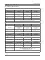
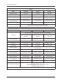
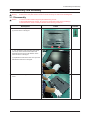
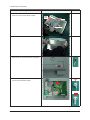
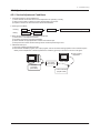
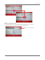
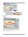
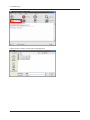
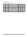
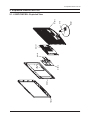
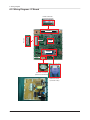
LCD-Monitor Chassis :LPU16YS LPU17NS LPU19YS / LPU19NS LPU20YS LPU22YS Model :B1630N B1730NW B1930N / B1930NW B2030N B2230N SERVICE TFT-LCD Monitor Manual Contens 1. Precautions 2. Product specifications 3. Disassembly and Reassemble 4. Troubleshooting 5. Exploded View & Part List 6. Wiring Diagram B1630N / B1730NW / B1930N B1930NW / B2030N / B2230N Refer to the service manual in the GSPN (see the rear cover) for the more information. Contents 1. Precautions 1-1. Safety Precautions.......................................................................................................... 1-1 1-2. Servicing Precautions...................................................................................................... 1-2 1-3. Static Electricity Precautions........................................................................................... 1-2 1-4. Installation Precautions................................................................................................... 1-3 2. Product specifications 2-1. Feature & Specifications.................................................................................................. 2-1 2-2. Spec Comparison to the Old Models............................................................................... 2-3 2-3. Accessories..................................................................................................................... 2-5 3. Disassembly and Assembly 3-1. Disassembly.................................................................................................................... 3-1 4. Troubleshooting 4-1. Troubleshooting............................................................................................................... 4-1 4-2. When the Power Does Not Turn On................................................................................ 4-2 4-3. When the screen is blank................................................................................................ 4-4 4-4. Error Examples and Actions............................................................................................ 4-8 4-5. Adjustment....................................................................................................................... 4-9 5. Exploded View & Part List 5-1. Exploded View................................................................................................................. 5-1 5-2. Parts List (B1630N)......................................................................................................... 5-2 5-3. Parts List (B1730NW)...................................................................................................... 5-7 5-4. Parts List (B1930N)....................................................................................................... 5-10 5-5. Parts List (B1930NW).................................................................................................... 5-15 5-6. Parts List (B2030N)....................................................................................................... 5-20 5-7. Parts List (B2230N)....................................................................................................... 5-23 6. Wiring Diagram 6-1. Wiring Diagram - Main Board.......................................................................................... 6-1 6-2. Wiring Diagram - IP Board............................................................................................... 6-4 6-3. Connector Functions....................................................................................................... 6-5 6-4. Cables............................................................................................................................. 6-5 GSPN (Global Service Partner Network) Area Web Site North America http://service.samsungportal.com Latin America http://latin.samsungportal.com CIS http://cis.samsungportal.com Europe http://europe.samsungportal.com China http://china.samsungportal.com Asia http://asia.samsungportal.com Mideast & Africa http://mea.samsungportal.com This Service Manual is a property of Samsung Electronics Co.,Ltd. Any unauthorized use of Manual can be punished under applicable International and/or domestic law. © 2009 Samsung Electronics Co.,Ltd. All rights reserved. Printed in Korea P/N: BN82-00841A-00 1. Precautions 1. Precautions 1-1. Safety Precautions Follow these safety, servicing and ESD precautions to prevent damage and to protect against potential hazards such as electrical shock. 1-1-1. Warnings 1. For continued safety, do not attempt to modify the circuit board. 2. Disconnect the AC power and DC power jack before servicing. 1-1-2. Servicing the LCD Monitor 1. When servicing the LCD Monitor, Disconnect the AC line cord from the AC outlet. 2. It is essential that service technicians have an accurate voltage meter available at all times. Check the calibration of this meter periodically. 1-1-3. Fire and Shock Hazard Before returning the monitor to the user, perform the following safety checks: 1. Inspect each lead dress to make certain that the leads are not pinched or that hardware is not lodged between the chassis and other metal parts in the monitor. 2. Inspect all protective devices such as nonmetallic control knobs, insulating materials, cabinet backs, adjustment and compartment covers or shields, isolation resistorcapacitor networks, mechanical insulators, etc. 3. Leakage Current Hot Check (Figure 1-1): WARNING : Do not use an isolation transformer during this test. Use a leakage current tester or a metering system that complies with American National Standards Institute (ANSI C101.1, Leakage Current for Appliances), and Underwriters Laboratories (UL Publication UL1410, 59.7). (READING SHOULD) NOT BE ABOVE 0.5mA LEAKAGE CURRENT TESTER DEVICE UNDER TEST TEST ALL EXPOSED METAL SURFACES 2-WIRE CORD *ALSO TEST WITH PLUG REVERSED (USING AC ADAPTER PLUG AS REQUIRED) EARTH GROUND Figure 1-1. Leakage Current Test Circuit 4. With the unit completely reassembled, plug the AC line cord directly into a 120V AC outlet. With the unit’s AC switch first in the ON position and then OFF, measure the current between a known earth ground (metal water pipe, conduit, etc.) and all exposed metal parts, including: metal cabinets, screwheads and control shafts. The current measured should not exceed 0.5 milliamp. Reverse the power-plug prongs in the AC outlet and repeat the test. 1-1-4. Product Safety Notices Some electrical and mechanical parts have special safetyrelated characteristics which are often not evident from visual inspection. The protection they give may not be obtained by replacing them with components rated for higher voltage, wattage, etc. Parts that have special safety characteristics are identified by on schematics and parts lists. A substitute replacement that does not have the same safety characteristics as the recommended replacement part might create shock, fire and/or other hazards. Product safety is under review continuously and new instructions are issued whenever appropriate. 1-1 1. Precautions 1-2. Servicing Precautions WARNING: An electrolytic capacitor installed with the wrong polarity might explode. Caution: Before servicing units covered by this service manual, read and follow the Safety Precautions section of this manual. Note: If unforeseen circumstances create conflict between the following servicing precautions and any of the safety precautions, always follow the safety precautions. 1-2-1 General Servicing Precautions 1. Always unplug the unit’s AC power cord from the AC power source and disconnect the DC Power Jack before attempting to: (a) remove or reinstall any component or assembly, (b) disconnect PCB plugs or connectors, (c) connect a test component in parallel with an electrolytic capacitor. 2. Some components are raised above the printed circuit board for safety. An insulation tube or tape is sometimes used. The internal wiring is sometimes clamped to prevent contact with thermally hot components. Reinstall all such elements to their original position. 3. After servicing, always check that the screws, components and wiring have been correctly reinstalled. Make sure that the area around the serviced part has not been damaged. 4. Check the insulation between the blades of the AC plug and accessible conductive parts (examples: metal panels, input terminals and earphone jacks). 5. Insulation Checking Procedure: Disconnect the power cord from the AC source and turn the power switch ON. Connect an insulation resistance meter (500 V) to theblades of the AC plug. The insulation resistance between each blade of the AC plug and accessible conductive parts (see above) should be greater than 1 megohm. 6. Always connect a test instrument’s ground lead to the instrument chassis ground before connecting the positive lead; always remove the instrument’s ground lead last. 1-3. Static Electricity Precautions Some semiconductor (solid state) devices can be easily damaged by static electricity. Such components are commonly called Electrostatically Sensitive Devices (ESD). Examples of typical ESD are integrated circuits and some field-effect transistors. The following techniques will reduce the incidence of component damage caused by static electricity. 1. Immediately before handling any semiconductor components or assemblies, drain the electrostatic charge from your body by touching a known earth ground. Alternatively, wear a discharging wrist-strap device. To avoid a shock hazard, be sure to remove the wrist strap before applying power to the monitor. 2. After removing an ESD-equipped assembly, place it on a conductive surface such as aluminum foil to prevent accumulation of an electrostatic charge. 3. Do not use freon-propelled chemicals. These can generate electrical charges sufficient to damage ESDs. 4. Use only a grounded-tip soldering iron to solder or desolder ESDs. 5. Use only an anti-static solder removal device. Some solder removal devices not classified as “anti-static” can generate electrical charges sufficient to damage ESDs. 6. Do not remove a replacement ESD from its protective package until you are ready to install it. Most replacement ESDs are packaged with leads that are electrically shorted together by conductive foam, aluminum foil or other conductive materials. 7. Immediately before removing the protective material from the leads of a replacement ESD, touch the protective material to the chassis or circuit assembly into which the device will be installed. Caution: Be sure no power is applied to the chassis or circuit and observe all other safety precautions. 8. Minimize body motions when handling unpackaged replacement ESDs. Motions such as brushing clothes together, or lifting your foot from a carpeted floor can generate enough static electricity to damage an ESD. 1-2 1. Precautions 1-4. Installation Precautions 1. For safety reasons, more than two people are required for carrying the product. 2. Keep the power cord away from any heat emitting devices, as a melted covering may cause fire or electric shock. 3. Do not place the product in areas with poor ventilation such as a bookshelf or closet. The increased internal temperature may cause fire. 4. Bend the external antenna cable when connecting it to the product. This is a measure to protect it from being exposed to moisture. Otherwise, it may cause a fire or electric shock. 5. Make sure to turn the power off and unplug the power cord from the outlet before repositioning the product. Also check the antenna cable or the external connectors if they are fully unplugged. Damage to the cord may cause fire or electric shock. 6. Keep the antenna far away from any high-voltage cables and install it firmly. Contact with the highvoltage cable or the antenna falling over may cause fire or electric shock. 7. When installing the product, leave enough space (10cm) between the product and the wall for ventilation purposes. A rise in temperature within the product may cause fire. 1-3 1. Precautions Memo 1-4 2. Product specifications 2. Product specifications 2-1. Feature & Specifications Feature Model B1630N B1730NW B1930N Brightness(Typical) 250 cd/m2 250 cd/m2 250 cd/m2 Response Time(Typical) 5ms 5ms 5ms Contrast Ratio(Typical) DC 50000:1 (Typ.500:1) DC 50000:1 (Typ.600:1) DC 50000:1 (Typ. 1000:1) Viewing Angle (Horizontal/Vertical) 90˚/ 65˚ (CR>10) 160˚/150˚ (CR>10) 170˚/160˚ (CR>10) Stand by Power(DPMS) <0.3W <0.3W <0.3W Special Features MagicBright3, MagicEco, MagicAngle, Off timer, Image Size, Color Effect,Customized key, Windows Vista Basic Specifications Model B1630N B1730NW B1930N TFT-LCD panel, RGB vertical stripe, normally white transmissive LCD Panel Scanning Frequency 15.6”Wide 0.252 mm(H) x 0.252 mm(V) pixel pitch 17”Wide 0.255 mm(H) x 0.255 mm(V) pixel pitch 18.5”Wide 0.3 mm(H) x 0.3 mm(V) pixel pitch Horizontal:30 ~ 61 kHz Vertical:56 ~ 75 Hz Horizontal:30 ~ 81 kHz Vertical:56 ~ 75 Hz Horizontal:31 ~ 80 kHz Vertical:56 ~ 75 Hz Color Supported 16.7M Resolution 1360 x 768 1440 x 900 1360 x 768 Input Signal 15.6” Analog 17” Analog 18.5” Analog Input Sync. Signal Separate H/V sync, Composite H/V, Sync-on-Green Level:TTL level Maximum Pixel Clock 90 MHz 136.75 MHz 89 MHz Active Display (Horizontal/Vertical) 344.232(H) x 193.536(V) 367.2(H) x 229.5(V) 409.8(H) x 230.4(V) AC power voltage & Frequency AC 110~130V, 60Hz & AC 200~240V, 50Hz Power consumption Less than 22W Less than 22W Dimension Set (W x H x D) 388 x 338 x 178mm 413 x 375 x 178mm Weight 2.65kg 2.9kg Environmental Considerations Less than 22W 455.6 x 375 x 178mm 3.55kg Operating Temperature: 10˚C ~ 40˚C(50˚F ~ 104˚F) Operating Humidity : 10% ~ 80% Operating Temperature: -25˚C ~ 45˚C(-13˚F ~ 113˚F) Operating Humidity: 5% ~ 90% Note: Designs and specifications are subject to change without prior notice. 2-1 2. Product specifications Feature Model B1930NW B2030N B2230N Brightness(Typical) 300 cd/m2 250 cd/m2 300 cd/m2 Response Time(Typical) 5ms 5ms 5ms Contrast Ratio(Typical) DC 70000:1 (Typ. 1000:1) DC 50000:1 (Typ. 1000:1) DC 70000:1 (Typ. 1000:1) Viewing Angle (Horizontal/Vertical) 160˚/160˚ (CR>10) 170˚/160˚ (CR>10) 170˚/160˚ (CR>10) Stand by Power(DPMS) <0.3W <0.3W <0.3W Special Features MagicBright3, MagicEco, MagicAngle, Off timer, Image Size, Color Effect,Customized key, Windows Vista Basic Specifications Model B1930NW B2030N B2230N TFT-LCD panel, RGB vertical stripe, normally white transmissive LCD Panel Scanning Frequency 19”Wide 20” Wide 0.2835 mm(H) x 0.2835 mm(V) 0.2768 mm(H) x 0.2768 mm(V) pixel pitch pixel pitch Horizontal:30 ~ 81 kHz Vertical:56 ~ 75 Hz Color Supported Horizontal:30 ~ 81 kHz Vertical:56 ~ 75 Hz Horizontal:31 ~ 80 kHz Vertical:50 ~ 75 Hz 16.7M Resolution 1440 x 900 1600 x 900 1920 x1 080 Input Signal 19” Analog 20” Analog 21.5” Analog Input Sync. Signal Separate H/V sync, Composite H/V, Sync-on-Green Level:TTL level Maximum Pixel Clock 137 MHz 150 MHz 162 MHz Active Display (Horizontal/Vertical) 408.24(H) x 255.15(V) 442.8(H) x 249.075(V) 476.64(H) x 268.11(V) AC power voltage & Frequency AC 110~130V, 60Hz & AC 200~240V, 50Hz Power consumption Less than 39W Less than 28W Less than 50W Dimension Set (W x H x D) 458 x 402 x 178mm 492 x 396 x 178mm 523.4 x 400 x 197mm Weight 3.95kg 4.1kg 4.35kg Environmental Considerations Operating Temperature: 10˚C ~ 40˚C(50˚F ~ 104˚F) Operating Humidity : 10% ~ 80% Operating Temperature: -25˚C ~ 45˚C(-13˚F ~ 113˚F) Operating Humidity: 5% ~ 90% Note: Designs and specifications are subject to change without prior notice. 2-2 21.5” Wide 0.24825 mm(H) x 0.24825 mm(V) pixel pitch 2. Product specifications 2-2. Spec Comparison to the Old Models Model B1630N / B1730NW / B1930N / B1930NW / B2030N / B2230N 633NW / 733NW / 933SN / 933NW / 2033SN / 2233SN 1360 x 768 (B1630N/B1930N) 1360 x 768 (633NW/933SN) 1440 x 900 (B1730NW/B1930NW) 1440 x 900 (733NW/933NW) 1600 x 900 (B2030N) 1600 x 900 (2033SN) 1920 x 1080 (B2230N) 1920 x 1080 (2233SN) Analog Analog 5ms 5ms 90/65(CR>10) (B1630N) 90/65(CR>10) (633NW) 160/150(CR>10) (B1730NW) 160/150(CR>10) (733NW) 160/160(CR>10) (B1930NW) 160/160(CR>10) (933NW) 170/160(CR>10) (B1930N/B2030N/B2230N) 170/160(CR>10) (933SN/2033SN/2233SN) 250 m² (B1630N/B1730NW/B1930N/B2030N) 250 m² (633NW/733NW/933SN/2033SN) 300 m² (B1930NW/B2230N) 300 cm² (933NW/2233SN) Design Resolution Input Response Time Viewing Angle Brightness Contrast MagicBright Feature 50,000:1(DC) (B1630N/B1730NW/B1930N/B2030N) 70,000:1(DC) (B1930NW/B2230N) 12,000:1(DC) (633NW) 15,000:1(DC) (733NW) 50,000:1(DC) (933SN/933NW/2033SN/2233SN) 4 Step 7 step MagicBright3 MagicEco MagicAngle Off timer Image Size Color Effect MagicBright3 Off timer Image Size Color Effect 2-3 2. Product specifications *Color Effect - Grey scale: Images are displayed in a grey tone on the screen. - Green: Images are displayed in a green tone on the screen. - Aqua: Images are displayed in a blue tone on the screen. - Sepia: Images are displayed in a brown tone on the screen. Image Size : If the resolution is not wide resolution, this option allows the screen size to be selected as normal or wide. *MagicAngle - Lean Back Mode1: Select when viewing from a slightly lower angle. - Lean Back Mode2: Select when viewing from the bottom. - Standing Mode: Select when viewing from the top. - Side Mode: Select when viewing from the left or right. - Custom: When <Custom> is selected, settings for <Lean Back Mode 1> is applied by default. User can set suitable picture quality as needed. *MagicEco - 100%: the power consumption is 100% of Default Setting. - 75%: the power consumption is 75% of Default Setting. - 50%: the power consumption is 50% of Default Setting. 2-4 2. Product specifications 2-3. Accessories Product Description Ccde. No Quick Setup Guide BN68-02480A Warranty Card (Not available in all locations) BN68-00226R User’s Guide, Monitor Driver, Natural Color Pro Software BN59-00982A D-sub Cable 1,500mm(1.5M) BN39-00244G Power Cord 1,830mm(1.8M) 3903-000452 Cleaning Cloth 160mm x 120mm BN63-02368B Remark Samsung Electronics Service center 2-5 2. Product specifications Memo 2-6 3. Disassembly and Assembly 3. Disassembly and Assembly This section describes the disassembly and reassembly sequences for this monitor. Warning:As this monitor has parts that are sensitive to static electricity, be careful when handling them. 3-1. Disassembly Caution: 1. Turn the monitor off before beginning the disassembly process. 2. When disassembling the monitor, do not use any metal tools except for the provided jig. 3. Disassemble the monitor carefully as directed in the following procedures. Description Photo Screws 1. Remove the stand body and then remove the two (2) screws shown in the figure. 2. ① Turn the monitor over and insert your hands into the top of the monitor at the center and separate the front cover in the direction of the arrow as shown in the figure. ② Separate the sides of the front cover up to the directed line as shown in the figure. 3. Turn the monitor over again to remove the back cover. 3-1 3. Disassembly and Assembly Description 4. Remove the LVDS, LAMP wire and FUNCTION cable then remove the SHIELD-COVER. Photo Screws LAMP WIRE LVDS FUNCTION 5. Remove the LCD panel. 6. Remove the two (2) screws shown in the figure. 7. Remove the four (4) screws shown in the figure and remove the Bracket support. 3-2 3. Disassembly and Assembly Description 8. Remove the main PCB and IP boards from the SHIELD-cover. Photo Screws IP-BOARD MAIN-BOARD ※The assembly is in the reverse order of disassembly. 3-3 3. Disassembly and Assembly Memo 3-4 4. Troubleshooting 4. Troubleshooting 4-1. Troubleshooting 1. Set custom mode as follows before beginning a repair. B1630N/B1930N B1730NW/B1930NW B2030N B2230N Resolution:1360x768 Resolution:1440x900 Resolution:1600x900 Resolution:1920 x 1080 V-frequency:60Hz V-frequency:75Hz V-frequency:60Hz V-frequency:60Hz H-frequency:47.7kHz H-frequency:70.6kHz H-frequency:60kHz H-frequency:67.5kHz 2. If the screen is blank, check whether the power cord is connected correctly. 3. The circuits to check: • When the raster does not appear: The Function PCB, Main PCB, I/P PBA • When 5V is generated but a blank screen is displayed: Main PCB • When 5V is not generated: I/P PBA 4. “Press the MENU button and hold down the, “ factory mode. (Enter, Source)” button for more than five (5) seconds to return the monitor to 4-1 4. Troubleshooting 4-2. When the Power Does Not Turn On Symptom -W hen turning on the Power button after connecting the power cable, the LED at the front of the monitor does not operate. -W hen turning on the Power button after connecting the power cable, the LED at the front of the monitor does not operate. Major checkpoints - Check the IP board power fuse and the IP board output power. - Check the connections for the IP board and the Main board inside the monitor. - Check the Main board power part and also check whether there is any abnormal output at any of the other output terminals. IC601 IC602 Diagnostics Yes 1 Is DC 5V measured at pins 6, 7 of the CN600 connector when pins 3, 4, 5 are 0V? Yes 2 Is DC 3.3V measured at pin 5 of IC601 when pin 4 is DC 5V? Check the connection status for the function assy. No Replace the IP board. No Check the circuits related to IC601. No Check the circuits related to IC602. Yes 3 Is DC 1.8V measured at pin 5 of IC602 when pin 4 is DC 5V? Yes Check and replace the IP board. Caution 4-2 Make sure to disconnect the power before working on the IP board. 4. Troubleshooting 4-2-1. Circuit diagrams when the power does not turn on 1 2 3 4-3 4. Troubleshooting 4-3. When the screen is blank Symptom - Even though the LED power turns on, the screen is blank when connecting the VGA cable. - Even though the LED power turns on, the screen is blank when connecting the VGA cable. Major checkpoints - Check the D-sub cable connections. - Check whether the LVDS cable is connected correctly to the panel. - Check whether the lamp connector of the panel is connected correctly to the IP board. CN400 X400 IC400 Check the signal cables and their connections. Diagnostics Yes 1 Is X400 oscillating correctly? No Check and replace the circuits related to X400. No Check the R204, R207, and R211 input terminals. No Check the circuits related to IC400. No Check the circuits related to CN400. No Check the +5V_Panel signal and the BL_EN signal. Yes 2 Do the RGB inputs appear at R204, R207, and R211? Yes Do the 3 Hsync and 4 Vsync waveforms appear at pins 14, 15 of IC400, respectively? Yes Do output signals appear at pins 8 to 30 of CN400? Yes Is DC 5V measured at pins 1, 2, and 3 of the CN400? Yes Check and replace the panel. Caution 4-4 Make sure to disconnect the power before working on the IP board. 4. Troubleshooting 4-3-1. When a blank screen is displayed 2 3 1 4 4-5 4. Troubleshooting B1730NW / B1930NW / B2030N / B2230N B1630N / B1930N 4-6 4. Troubleshooting 4-3-2. Waveforms when no screen is displayed 1 3 4 4-7 4. Troubleshooting 4-4. Error Examples and Actions Error Appearance 4-8 Symptoms and Actions Remarks Symptom:A full white screen is displayed regardless of the signals when turning on the monitor. * A Full White pattern is a feature of a TN panel when no video signals are supplied. Cause: This error occurs when only lamp power is supplied and the video signals are not input to the panel due to an LVDS cable connection error. Action: Replace the LVDS cable or connect the cable correctly so that the video signals can be supplied to the panel. 4. Troubleshooting 4-5. Adjustment 4-5-1. Service Adjustment Conditions 1. Precautions before a Service Adjustment 1) Check whether the devices for the service adjustment are operating normally. 2) Secure a space that is sufficiently wide for disassembling the monitor. 3) Prepare a soft mat on which the monitor will be disassembled. 2. Entering Service Mode Entering: Exiting: Menu Power OFF Brightness 0 Contrast 0 Hold down the Enter button for five (5) seconds. Power ON 3. Basic Service Items to Perform after Replacing a Board 1) Check the PC color adjustment status. 2) Input DDC (input both of Analog and Digital). 3) Check whether the appropriate MCU code for the model is input. 4) Hard power the monitor off after entering service mode and performing a reset. 4. DDC EDIT Data Input 1) Use when updating the AD board code. 2) Download the WinDDC program, DDC Input program, and Hex and DDC files appropriate to the model through the Quality Control department of Samsung Electronics. Install the jig and input the data, as shown in the figure. Monitor needing adjustment Parallel Connector (25P Cable) MTI-2055 DDC Manger Connect Monitor (Signal Cable) 4-9 4. Troubleshooting 4-5-2. Service Function Specifications Checking the Code Version 1. Check the MCU code version and checksum after entering SVC Mode. 2. E ntering SVC Mode - Adjust the Brightness and Contrast values to 0. - Hold down the Enter button for five (5) seconds. - The SVC Function OSD is displayed. - To exit the SVC Function, turn the power off. 3. S afe Mode - When the input signal is higher than the supported frequency of the product, safe mode gives users some time (one minute) to change the video card settings to the Recommended Mode settings. Panel information Select the Auto Auto option Select the PixelShift option. Country Scaler Vender Micom version Micom checksum Service Mode (Moving around) 1. Press the - button to move to other items. 4-10 4. Troubleshooting 2. Press the - button to change the setting to On or Off. When replacing the panel After replacing the panel, move to the Panel item and hold down the Menu button for five (5) seconds. The Ch. No is incremented by 1 and then both the On Time and Cycle are set to 0. This number is incremented by 1. 4-11 4. Troubleshooting Inputting the DDC Data 1 2 3 4 5 Use the DDC Manager MTI-2050 version or later. 1) Click the Open [F5] icon. 2) Select a port. 3) Open a DDC file. 4) Select a date and click the OK [Save] button. 5) Click the Next [OK] button. 6 6) Enter the serial number and then press the Enter button ※When inputting digital data after inputting analog data, repeat steps 2 to 5. 4-12 4. Troubleshooting Inputting the MCU Data 1) Check the following options after open the “Easywriter” - Option: Setup ISP tool 1 - LPT Port Offset: 378 - ISP Jig type Selection: SAMSUNG - Auto detect - Confirm Change 4-13 4. Troubleshooting 2) Click the Load File button. 2 3) Select an MCU code file, and then click the Open[O] button. 4-14 4. Troubleshooting 4) Click the Auto button. 4 5) When programming and verification are complete, hard power the monitor off and then on again. 4-15 4. Troubleshooting Memo 4-16 5. Exploded View & Part List 5. Exploded View & Part List M0027 STD T0003 M0215 M0014 M0174 M0107 M0013 5-1. LS20PUYKF/EN - Exploded View 5-1 5. Exploded View & Part List 5-1-1. LS20PUYKF/EN - Parts List Location No. Code No. Description & Specification Q’ty SA/SNA M0013 BN96-12499B ASSY COVER P-REAR;PLUM 20 analog,HIPS,HB 1 SA M0014 BN94-03228H ASSY PCB MAIN;LS20PUYKF/EN 1 SA M0027 BN96-12486A ASSY STAND P-BASE;PLUM 15~20,ABS+PMMA(SF 1 SA STD BN96-12487A ASSY STAND P-BODY;PLUM 23,ABS+PMMA(SF-09 1 SA M0107 BN63-06352B SHIELD-COVER;PLUM 20 analog,SECC,T0.8 1 SNA M0174 BN44-00327C IP BOARD;IP-29155A,PLUM20"w(2Lamp),0.7~1 1 SA M0215 BN07-00624A LCD-PANEL;LTM200KT03,SSUTTT,6Bit + Hi-FR 1 SA T0003 BN96-12497A ASSY COVER P-FRONT;PLUM 20,ABS+PMMA,HB,B 1 SA 5-2 Remark 5. Exploded View & Part List 5-2. LS20PUYKF/EN - Parts List Service Bom (SA: SERVICE AVAILABLE, SNA: SERVICE NOT AVAILABLE) Level Location No. 0.1 Code No. Description & Specification Q’ty SA/SNA Remark BN90-02395A ASSY COVER FRONT;B2030,H/GLOSSY 1 SNA 1 SA 2 SA ..2 T0003 BN96-12497A ASSY COVER P-FRONT;PLUM 20,ABS+PMMA,HB,B ...3 W392 6003-000282 SCREW-TAPTYPE;BH,+,-,B,M3,L8,ZPC(BLK),SW BN61-05972A GUIDE-PANEL;PLUM 23,SECC,T0.8 1 SNA ...3 CCM1 BN63-02183D COVER-SHEET;Rhcm,PE Vinyl,T0.04,680mm,20 0.45 SNA ...3 M0112 BN63-06350A COVER-FRONT;PLUM 20,PMMA+ABS,HB,BK23,SF- 1 SNA ...3 ...3 BN64-01234A DECORATION;PLUM 20,PC,CLEAR 1 SNA ...3 AL093 BN67-00280A LENS-LED;PLUM23'',PC CLEAR,TP26 1 SNA ...3 T0527 BN68-00798D LABEL-ENERGY,STAR;L/M,W/W,PET,T0.05,9.3, 1 SNA ...3 M0175 BN96-12804B ASSY BOARD P-TOUCH FUNCTION;plum (all mo 1 SA BN94-03258A ASSY PCB FUNCTION-BN9612804B;PLUM,BN96- 1 SNA BN39-01164C LEAD CONNECTOR;plum,UL1061#28,5P,80mm ,12 1 SA .....5 BN61-05967A HOLDER-CONTROL;plum23",ABS HB,WH12 1 SNA .....5 BN97-03998A ASSY SMD-BN96-12804B;PLUM,BN96-12804B 1 SNA ......6 0406-001253 DIODE-TVS;VESD05A1-02V,6.0/6.8/7.5V,SOD- 2 SNA 0601-002642 LED;SMD(SIDE VIEW),BLUE,475nm,3.8x1.0x0. 1 SNA 1209-001890 IC-SENSOR;CT1N07B,MLF,24P,4x4mm,PLAST IC, 1 SA ....4 .....5 ......6 M2893 L0405 ......6 ......6 HDR7 2007-000139 R-CHIP;220ohm,5%,1/16W,TP,1005 6 SNA ......6 MR306 2007-000141 R-CHIP;2.2Kohm,5%,1/16W,TP,1005 2 SNA ......6 R111 2007-000171 R-CHIP;0ohm,5%,1/16W,TP,1005 2 SNA 2007-001329 R-CHIP;7.5Kohm,5%,1/16W,TP,1005 2 SA 2203-006399 C-CER,CHIP;1000nF,10%,6.3V,X5R,1005 1 SA 3711-007275 CONNECTORHEADER;BOX,5P,1R,1.25mm,SMD-S, 1 SA BN41-01342A PCB SUB-TOUCH FUNCTION;Plum(all),FR-4,2, 1 SNA .....5 BN74-00057A TAPE-FUNCTION;DOUBLE FACE TAPE,Polyester 1 SNA .....5 BN74-00058A TAPE-FUNCTION;DOUBLE FACE TAPE,Polyester 2 SNA 6003-000115 SCREW-TAPTYPE;BH,+,B,M3,L6,ZPC(BLK),SW RC 2 SNA BN68-02526A LABEL-MONITOR-POP;Plum POP,WW,PET,T0.05, 1 SNA BN90-02396B ASSY COVER REAR;B2030N,HIGH GLOSSY 1 SNA 2 SA ......6 ......6 ......6 AD480 CN906 ......6 ...3 M0081 ..2 0.1 M0002 ..2 W391 6003-000275 SCREW-TAPTYPE;BH,+,B,M3,L10,ZPC(BLK),S WR ..2 M0013 BN96-12499B ASSY COVER P-REAR;PLUM 20 analog,HIPS,HB 1 SA ...3 M0081 6003-001001 SCREW-TAPTYPE;FH,+,B,M3,L8,ZPC(BLK),SW RC 1 SNA ...3 M0081 6003-001239 SCREW-TAPTYPE;FH,+,B,M4,L10,ZPC(WHT),S WR 2 SNA ...3 M0113 BN61-01581A BRACKET-VESA;BI17/19BS,SECC,T1.0 2 SNA ...3 T0060 BN61-05091A SPRING ETC-STAND;ECOFIT 23",SK5,T0.3 1 SNA ...3 T0060 BN61-05968A SPRING ETC;PLUM 23,SK5,T0.6,BLACK 1 SNA ...3 CIS4 BN61-05971A HOLDER-STAND;PLUM 23,POM,WHITE,ACETAL 1 SNA 5-3 5. Exploded View & Part List Level Location No. Code No. Description & Specification Q’ty ...3 M0111 BN63-06314A COVERSTAND;PLUM23,ABS+PMMA,HB,BK23,H/GL 1 SNA ...3 M0006 BN63-06351B COVER-REAR;PLUM 20 analog,HIPS,HB,BK23 1 SNA BN63-06357A SHIELD-LAMP;PLUM 20'',SPTE,T0.3 1 SNA ...3 ...3 M0131 0.1 BP63-00786A GASKET;HLS6187WX/XAA,Conductive Adhesive 1 SNA BN91-03053B ASSY LCD-STZ;LS20MY* 1 SNA ..2 M0215 BN07-00624A LCD-PANEL;LTM200KT03,SSUTTT,6Bit + Hi-FR 1 SA 0.1 M0017 BN91-04660H ASSY CHASSIS;LS20PUYKF/EN 1 SNA ..2 M0081 6003-000264 SCREW-TAPTYPE;PWH,+,,B,M3,L6,ZPC(WHT),S 2 SA ..2 M0174 BN44-00327C IP BOARD;IP-29155A,PLUM20"w(2Lamp),0.7~1 1 SA ..2 T0527 BN68-00931A LABEL;ALL,S.MARINA,PREMIUM TRANSFER,T 0. 1 SNA ..2 M0014 BN94-03228H ASSY PCB MAIN;LS20PUYKF/EN 1 SA ...3 0202-001463 SOLDER-WIRE;LFC2-W3.0,-,D3,99.79Sn/0.2Cu 1.814 SNA ...3 0202-001521 SOLDER-WIRE FLUX;ECO SOLDER RMA98 SUP,D1 0.003 SNA ...3 0204-003399 FLUX;AGF-780 DS-AA15,13.0% 2.259 SNA ...3 0204-003403 ISOPROPYL ALCOHOL;FLUX REDUCER #5080,GRA 3.47 SNA ...3 3701-001510 CONNECTOR-DSUB;15P,3R,FEMAIL,STAMPED PIN 1 SNA ...3 CN906 3711-005847 CONNECTORHEADER;BOX,9P,1R,2MM,ANGLE,SN, 1 SNA ...3 T0527 BN68-00795A LABEL-IC MICOM;MATISSE,GOYA,ART PAPER(10 1 SNA ...3 T0174 BN97-03933H ASSY SMD;LS20PUYKF/EN 1 SNA ....4 0202-001477 SOLDER-CREAM;LST309M,D20~45um,96.5Sn/3A 0.462 SNA ....4 0401-001056 DIODE-SWITCHING;MMBD4148SE,100V,200m A,SO 3 SA ....4 MZD1 ....4 5-4 SA/SNA Remark 0403-001411 DIODE-ZENER;5.49-5.73V,200mW,SOD-323,TP 8 SA 0403-001712 DIODE-ZENER;QZX363C6V8,6.47/7.14V,200mW, 1 SNA ....4 PQ02 0501-002080 TR-SMALL SIGNAL;2SC2412K,NPN,200mW,SC-59 1 SA ....4 Q409 0505-001165 FET-SILICON;Si3443CDV,P,-20V,+-4.4A,65mo 1 SA ....4 IC112 1103-000129 IC-EEPROM;24C02,2Kbit,256x8,SOP,8P,5x4mm 1 SA ....4 IC112 1103-001410 IC-EEPROM;S-24CS08AFJ-TB-1GE,8Kbit,1Kx8, 1 SA ....4 IC109 1205-003895 IC-LCD CONTROLLER;SE919LMNT,QFP,64P,7x7 1 SA ....4 DR1 2007-000043 R-CHIP;1Kohm,1%,1/10W,TP,1608 6 SA ....4 CER02 2007-000071 R-CHIP;22ohm,5%,1/10W,TP,1608 2 SNA ....4 AR30 2007-000074 R-CHIP;100ohm,5%,1/10W,TP,1608 20 SA ....4 AVR51 2007-000083 R-CHIP;3Kohm,5%,1/10W,TP,1608 1 SNA ....4 CER04 2007-000084 R-CHIP;4.7Kohm,5%,1/10W,TP,1608 2 SA ....4 MROP1 2007-000090 R-CHIP;10Kohm,5%,1/10W,TP,1608 12 SA ....4 AR108 2007-000097 R-CHIP;47Kohm,5%,1/10W,TP,1608 5 SA ....4 ARR2 2007-000102 R-CHIP;100Kohm,5%,1/10W,TP,1608 2 SA ....4 ZR24 2007-000109 R-CHIP;1Mohm,5%,1/10W,TP,1608 1 SNA ....4 KAR11 2007-000124 R-CHIP;2.2Kohm,5%,1/10W,TP,1608 3 SNA ....4 HR13 2007-000821 R-CHIP;390ohm,1%,1/10W,TP,1608 1 SNA ....4 ZR10 2007-001164 R-CHIP;75ohm,1%,1/10W,TP,1608 3 SNA ....4 R1 2007-002425 R-CHIP;1ohm,5%,1/10W,TP,1608 6 SNA ....4 C134 2203-000257 C-CER,CHIP;10nF,10%,50V,X7R,TP,1608 1 SA 5. Exploded View & Part List Level Location No. Code No. Description & Specification Q’ty ....4 C409 ....4 ZC14 ....4 DC108 ....4 PC11 ....4 C125 SA/SNA Remark 2203-000292 C-CER,CHIP;0.01nF,5%,50V,C0G,1608 2 SA 2203-000626 C-CER,CHIP;0.022nF,5%,50V,C0G,1608 1 SNA 2203-005005 C-CER,CHIP;100nF,10%,16V,X7R,1608 25 SC 2203-006141 C-CER,CHIP;1000nF,10%,16V,X5R,1608 2 SNA 2203-006361 C-CER,CHIP;10000nF,10%,10V,X5R,TP,2012 18 SC 1 SA ....4 X202 2801-003773 CRYSTAL-SMD;12MHz,30ppm,28AAN,20pF,50oh ....4 T0568 3301-001407 BEAD-SMD;30ohm,1608,300mA,TP,,,0.4ohm 2 SNA ....4 AC510 3708-001150 CONNECTOR-FPC/FFC/PIC;30P,1mm,SMDA,SN,Y 1 SA 3711-005743 HEADER-BOARD TO CABLE;BOX,5P,1R,1.25mm,A 1 SA ....4 ....4 T0077 BN41-01310A PCB MAIN;PLUM B2230N,CEM-3,2,MP1.0,1.6,5 1 SNA ....4 T0527 BN68-00931A LABEL;ALL,S.MARINA,PREMIUM TRANSFER,T 0. 1 SNA ....4 M0018 BN97-03932H ASSY MICOM;B2030N 1 SNA .....5 IC115 1107-001580 IC-FLASH MEMORY;MX25L4005,4Mbit,512Kx8,S 1 SNA 0402-001614 DIODE-RECTIFIER;S1G,400V,1A,DO-214AC,TP 1 SA 3301-001145 BEAD-SMD;60ohm,4516,TP,70ohm/45MHz,82o hm 4 SNA ....4 ....4 L2011 ....4 T0087 1203-006118 IC-POSI.FIXED REG.;S-1172B18-U5T1G,SOT-8 1 SA ....4 T0087 1203-006141 IC-POSI.FIXED REG.;S-1172B33-U5T1G,SOT-8 1 SA ....4 6MC22 2203-000975 C-CER,CHIP;47nF,10%,25V,X7R,TP,1608,- 6 SNA ....4 C3 2203-000384 C-CER,CHIP;0.015nF,5%,50V,C0G,1608 1 SNA ..2 M0006 BN96-12500B ASSY SHIELD P-COVER;PLUM 20 analog,SECC, 1 SNA BN61-05973A STUD-PEM;PLUM23'',M4,D8,L20 2 SNA ...3 ...3 M0107 BN63-06352B SHIELD-COVER;PLUM 20 analog,SECC,T0.8 1 SNA ...3 M0131 BN63-00049A GASKET;RB17AS,Conductive Fabric,1.5MM,10 1 SNA ...3 M0131 BN63-03474A GASKET;HUBBLE 27",Polyurethane+Polyester 4 SNA 2 SA ..2 T0081 6001-002408 SCREW-MACHINE;BH,+,WT,M4,L12,ZPC(WHT ),SW ..2 M0214 BN96-02854W ASSY CABLE P-FLAT CABLE;MCKINLEY,FLAT CA 1 SA ..2 T0527 BN68-00513A LABEL-E,PASS;ALL MODEL,YUPO(110G),50X15, 1 SNA BN91-04672A ASSY SHIELD;B2030 1 SNA 0.1 ..2 CIS1 0203-001598 TAPE-FILAMENT;#8915,0.15,12,55000,CLR 0.24 SNA BN92-05472M ASSY BOX;LS20PUYKF/EN 1 SNA BH68-00329D LABEL BAR CODE-02;NO CE,NO WT`Y,MPRII,LA 1 SNA ..2 BH68-00656A LABEL BOX-00;ALL MODEL,MOJO 90G,90,95,WH 1 SNA ..2 BN69-04365A BOX-02,SET;B2030,CB,A-01,SW2, ECT 40,YEL 1 SNA 0.1 BN92-05473A ASSY P/MATERIAL;LS20PUZKFV/ZC 1 SNA 0203-001100 TAPE-OPP MASKING;OPP/W75/ CLR,T0.075,W75, 1.41 SNA 6902-000061 BAG AIR;LDPE,T0.2,W500,L1000,TRP,370.000 1 SNA 6902-000241 BAG PE;HDPE/NITRON,T0.5/T0.012,W600,L600 1 SNA ..2 6902-000379 BAG AIR;LDPE,T0.2,W1000,L1800,TRP,1260.0 1 SNA ..2 6902-000604 BAG WRAPPING;LDPE,T0.02,W500,L10000,TRP, 2.04 SNA ..2 6902-000609 BAG ROLL;LDPE,T0.05,W2400,L1000,TRP,30.0 0.02 SNA BH68-40364A LABEL-SUMMARY;G52,G72,ART,100G,WHT,BL K,W 1 SNA BH69-00457C PACKING INNER-00,PAD;COMM,T3.0,880,1320, 1 SNA BN68-00129A LABEL SHIPPING-00;LABEL SHIPPING,ART-PAP 1 SNA BN69-00391P PAD-ANGLE;T4,50,2200,YEL,56g 1 SNA 0.1 ..2 ..2 T0077 S.N.A ..2 ..2 ..2 T0524 T0527 ..2 ..2 ..2 T0527 5-5 5. Exploded View & Part List Level Location No. ..2 ..2 Description & Specification Q’ty SA/SNA Remark BN69-03093A PALLETWOOD;2033SW,WOOD,L1135,W815,H120, 1 SNA BN69-03565T PAD-PLATE;B2030,CB,SW,YEL,W1100,D780 1 SNA ..2 T0246 BN69-04302A CUSHION-SET;PLUM 20,EPS,WHITE 1 SNA 0.1 M0045 BN92-05474L ASSY ACCESSORY;LS20PUYKF/EN 1 SNA 1 SA ..2 T0268 3903-000452 CBF-POWER CORD;DT,EU/KR,CP3,IEC320 C13,2 ..2 M0114 BN39-00244G CBF SIGNAL;D-sub cable,15P/15P,20276N,15 1 SA ..2 M0027 BN96-12486A ASSY STAND P-BASE;PLUM 15~20,ABS+PMMA(SF 1 SA ...3 T0524 6902-000109 BAG PE;HDPE,T0.015,W350,L430,TRP,28,2,4. 1 SNA ...3 CIS4 BN61-01717A HOLDER-STAND;BIZET,NI PLT,CH,+,M4,L11(5) 1 SNA ...3 CCM1 BN63-02183K COVER-SHEET;Rhcm,PE Vinyl,T 0.04,250MM,2 0.3 SNA ...3 BN63-06315A COVER-STAND BASE;PLUM 20,ABS+PMMA(SF-095 1 SNA ...3 BN68-02482A MANUAL FLYER-STAND;Plum,Mojo 80g,148,210 1 SNA BN73-00077A RUBBER FOOT;MATISSE,BUMPON,#13.5,T2.0 ,60 4 SNA BN68-02466A LABEL-STICKER;PLUM,ALL,ART PAPER,50,10,S 1 SNA 1 SA ...3 AR011 ...3 ..2 STD BN96-12487A ASSY STAND P-BODY;PLUM 23,ABS+PMMA(SF-09 ...3 T0524 6902-000023 BAG PE;LDPE,T0.08,W150,L120,TRP,1.650g 1 SNA ...3 BN61-05969A STAND-BAR;PLUM 23,ABS+PMMA(SF0950),BK23 1 SNA ....4 BN61-05970A STAND-BAR IN;PLUM 23,ABS+PMMA(SF0950),B 1 SNA .....5 BN61-02932E BRACKET-STOPPER NUT;ECOFIT 20,M4,D8,L12, 1 SNA BN63-02183C COVER-SHEET;Rhcm,PE Vinyl,T0.04,200mm,20 0.1 SNA BN68-02466C LABEL-STICKER;PLUM,ALL,ART PAPER,50,10,S 1 SNA BN96-12572E ASSY ACCESSORY;LS20PUYKF/EN 1 SA ...3 CCM1 ...3 ..2 M0045 ...3 PE BAG 6902-000009 BAG PE;HDPE,T0.03,W240,L400,TRP,8,2,-,5. 1 SNA ...3 M0019 BH68-70448A CARD-01;TFT LCD,SRC,RUSSIA,S/W,120,W210* 1 SNA BN59-00982A S/W DRIVER-03,IB;PLUM Project,W/W,SyncMa 1 SNA M9889 BN63-02368B CLOTH-CLEAN;cloth,120,160,sea blue,ToC 1 SNA ...3 BN68-00226R MANUAL FLYER-03,WARRANTY CARD;comm,Samsu 1 SNA ...3 BN68-00907F MANUAL FLYER00,WEE;comm,Samsung,23Lang, 1 SNA ...3 BN68-01925G MANUAL FLYER-WARRANTY CARD;comm,Samsung, 1 SNA ...3 BN68-02480A MANUAL FLYER-QSG,02;PLUM Project MODELS, 1 SNA ...3 BN68-02462B LABEL-STICKER;CIS,T0.05,93,40,TV-MONITOR 1 SNA 0.1 BN92-05486A ASSY LABEL;PLUM , BLACK,W/W 1 SNA BN68-01570A LABEL RATING;ALL,SS,PE,T0.05,90,45,Dark 1 SNA ...3 ...3 ..2 5-6 Code No. CCM1 5. Exploded View & Part List 5. Exploded View & Part List M0027 STD T0003 M0215 M0014 M0174 M0107 M0013 5-1. LS20PUYKF/EN - Exploded View 5-1 5. Exploded View & Part List 5-1-1. LS20PUYKF/EN - Parts List Location No. Code No. Description & Specification Q’ty SA/SNA M0013 BN96-12499B ASSY COVER P-REAR;PLUM 20 analog,HIPS,HB 1 SA M0014 BN94-03228H ASSY PCB MAIN;LS20PUYKF/EN 1 SA M0027 BN96-12486A ASSY STAND P-BASE;PLUM 15~20,ABS+PMMA(SF 1 SA STD BN96-12487A ASSY STAND P-BODY;PLUM 23,ABS+PMMA(SF-09 1 SA M0107 BN63-06352B SHIELD-COVER;PLUM 20 analog,SECC,T0.8 1 SNA M0174 BN44-00327C IP BOARD;IP-29155A,PLUM20"w(2Lamp),0.7~1 1 SA M0215 BN07-00624A LCD-PANEL;LTM200KT03,SSUTTT,6Bit + Hi-FR 1 SA T0003 BN96-12497A ASSY COVER P-FRONT;PLUM 20,ABS+PMMA,HB,B 1 SA 5-2 Remark 5. Exploded View & Part List 5-2. LS20PUYKF/EN - Parts List Service Bom (SA: SERVICE AVAILABLE, SNA: SERVICE NOT AVAILABLE) Level Location No. 0.1 Code No. Description & Specification Q’ty SA/SNA Remark BN90-02395A ASSY COVER FRONT;B2030,H/GLOSSY 1 SNA 1 SA 2 SA ..2 T0003 BN96-12497A ASSY COVER P-FRONT;PLUM 20,ABS+PMMA,HB,B ...3 W392 6003-000282 SCREW-TAPTYPE;BH,+,-,B,M3,L8,ZPC(BLK),SW BN61-05972A GUIDE-PANEL;PLUM 23,SECC,T0.8 1 SNA ...3 CCM1 BN63-02183D COVER-SHEET;Rhcm,PE Vinyl,T0.04,680mm,20 0.45 SNA ...3 M0112 BN63-06350A COVER-FRONT;PLUM 20,PMMA+ABS,HB,BK23,SF- 1 SNA ...3 ...3 BN64-01234A DECORATION;PLUM 20,PC,CLEAR 1 SNA ...3 AL093 BN67-00280A LENS-LED;PLUM23'',PC CLEAR,TP26 1 SNA ...3 T0527 BN68-00798D LABEL-ENERGY,STAR;L/M,W/W,PET,T0.05,9.3, 1 SNA ...3 M0175 BN96-12804B ASSY BOARD P-TOUCH FUNCTION;plum (all mo 1 SA BN94-03258A ASSY PCB FUNCTION-BN9612804B;PLUM,BN96- 1 SNA BN39-01164C LEAD CONNECTOR;plum,UL1061#28,5P,80mm ,12 1 SA .....5 BN61-05967A HOLDER-CONTROL;plum23",ABS HB,WH12 1 SNA .....5 BN97-03998A ASSY SMD-BN96-12804B;PLUM,BN96-12804B 1 SNA ......6 0406-001253 DIODE-TVS;VESD05A1-02V,6.0/6.8/7.5V,SOD- 2 SNA 0601-002642 LED;SMD(SIDE VIEW),BLUE,475nm,3.8x1.0x0. 1 SNA 1209-001890 IC-SENSOR;CT1N07B,MLF,24P,4x4mm,PLAST IC, 1 SA ....4 .....5 ......6 M2893 L0405 ......6 ......6 HDR7 2007-000139 R-CHIP;220ohm,5%,1/16W,TP,1005 6 SNA ......6 MR306 2007-000141 R-CHIP;2.2Kohm,5%,1/16W,TP,1005 2 SNA ......6 R111 2007-000171 R-CHIP;0ohm,5%,1/16W,TP,1005 2 SNA 2007-001329 R-CHIP;7.5Kohm,5%,1/16W,TP,1005 2 SA 2203-006399 C-CER,CHIP;1000nF,10%,6.3V,X5R,1005 1 SA 3711-007275 CONNECTORHEADER;BOX,5P,1R,1.25mm,SMD-S, 1 SA BN41-01342A PCB SUB-TOUCH FUNCTION;Plum(all),FR-4,2, 1 SNA .....5 BN74-00057A TAPE-FUNCTION;DOUBLE FACE TAPE,Polyester 1 SNA .....5 BN74-00058A TAPE-FUNCTION;DOUBLE FACE TAPE,Polyester 2 SNA 6003-000115 SCREW-TAPTYPE;BH,+,B,M3,L6,ZPC(BLK),SW RC 2 SNA BN68-02526A LABEL-MONITOR-POP;Plum POP,WW,PET,T0.05, 1 SNA BN90-02396B ASSY COVER REAR;B2030N,HIGH GLOSSY 1 SNA 2 SA ......6 ......6 ......6 AD480 CN906 ......6 ...3 M0081 ..2 0.1 M0002 ..2 W391 6003-000275 SCREW-TAPTYPE;BH,+,B,M3,L10,ZPC(BLK),S WR ..2 M0013 BN96-12499B ASSY COVER P-REAR;PLUM 20 analog,HIPS,HB 1 SA ...3 M0081 6003-001001 SCREW-TAPTYPE;FH,+,B,M3,L8,ZPC(BLK),SW RC 1 SNA ...3 M0081 6003-001239 SCREW-TAPTYPE;FH,+,B,M4,L10,ZPC(WHT),S WR 2 SNA ...3 M0113 BN61-01581A BRACKET-VESA;BI17/19BS,SECC,T1.0 2 SNA ...3 T0060 BN61-05091A SPRING ETC-STAND;ECOFIT 23",SK5,T0.3 1 SNA ...3 T0060 BN61-05968A SPRING ETC;PLUM 23,SK5,T0.6,BLACK 1 SNA ...3 CIS4 BN61-05971A HOLDER-STAND;PLUM 23,POM,WHITE,ACETAL 1 SNA 5-3 5. Exploded View & Part List Level Location No. Code No. Description & Specification Q’ty ...3 M0111 BN63-06314A COVERSTAND;PLUM23,ABS+PMMA,HB,BK23,H/GL 1 SNA ...3 M0006 BN63-06351B COVER-REAR;PLUM 20 analog,HIPS,HB,BK23 1 SNA BN63-06357A SHIELD-LAMP;PLUM 20'',SPTE,T0.3 1 SNA ...3 ...3 M0131 0.1 BP63-00786A GASKET;HLS6187WX/XAA,Conductive Adhesive 1 SNA BN91-03053B ASSY LCD-STZ;LS20MY* 1 SNA ..2 M0215 BN07-00624A LCD-PANEL;LTM200KT03,SSUTTT,6Bit + Hi-FR 1 SA 0.1 M0017 BN91-04660H ASSY CHASSIS;LS20PUYKF/EN 1 SNA ..2 M0081 6003-000264 SCREW-TAPTYPE;PWH,+,,B,M3,L6,ZPC(WHT),S 2 SA ..2 M0174 BN44-00327C IP BOARD;IP-29155A,PLUM20"w(2Lamp),0.7~1 1 SA ..2 T0527 BN68-00931A LABEL;ALL,S.MARINA,PREMIUM TRANSFER,T 0. 1 SNA ..2 M0014 BN94-03228H ASSY PCB MAIN;LS20PUYKF/EN 1 SA ...3 0202-001463 SOLDER-WIRE;LFC2-W3.0,-,D3,99.79Sn/0.2Cu 1.814 SNA ...3 0202-001521 SOLDER-WIRE FLUX;ECO SOLDER RMA98 SUP,D1 0.003 SNA ...3 0204-003399 FLUX;AGF-780 DS-AA15,13.0% 2.259 SNA ...3 0204-003403 ISOPROPYL ALCOHOL;FLUX REDUCER #5080,GRA 3.47 SNA ...3 3701-001510 CONNECTOR-DSUB;15P,3R,FEMAIL,STAMPED PIN 1 SNA ...3 CN906 3711-005847 CONNECTORHEADER;BOX,9P,1R,2MM,ANGLE,SN, 1 SNA ...3 T0527 BN68-00795A LABEL-IC MICOM;MATISSE,GOYA,ART PAPER(10 1 SNA ...3 T0174 BN97-03933H ASSY SMD;LS20PUYKF/EN 1 SNA ....4 0202-001477 SOLDER-CREAM;LST309M,D20~45um,96.5Sn/3A 0.462 SNA ....4 0401-001056 DIODE-SWITCHING;MMBD4148SE,100V,200m A,SO 3 SA ....4 MZD1 ....4 5-4 SA/SNA Remark 0403-001411 DIODE-ZENER;5.49-5.73V,200mW,SOD-323,TP 8 SA 0403-001712 DIODE-ZENER;QZX363C6V8,6.47/7.14V,200mW, 1 SNA ....4 PQ02 0501-002080 TR-SMALL SIGNAL;2SC2412K,NPN,200mW,SC-59 1 SA ....4 Q409 0505-001165 FET-SILICON;Si3443CDV,P,-20V,+-4.4A,65mo 1 SA ....4 IC112 1103-000129 IC-EEPROM;24C02,2Kbit,256x8,SOP,8P,5x4mm 1 SA ....4 IC112 1103-001410 IC-EEPROM;S-24CS08AFJ-TB-1GE,8Kbit,1Kx8, 1 SA ....4 IC109 1205-003895 IC-LCD CONTROLLER;SE919LMNT,QFP,64P,7x7 1 SA ....4 DR1 2007-000043 R-CHIP;1Kohm,1%,1/10W,TP,1608 6 SA ....4 CER02 2007-000071 R-CHIP;22ohm,5%,1/10W,TP,1608 2 SNA ....4 AR30 2007-000074 R-CHIP;100ohm,5%,1/10W,TP,1608 20 SA ....4 AVR51 2007-000083 R-CHIP;3Kohm,5%,1/10W,TP,1608 1 SNA ....4 CER04 2007-000084 R-CHIP;4.7Kohm,5%,1/10W,TP,1608 2 SA ....4 MROP1 2007-000090 R-CHIP;10Kohm,5%,1/10W,TP,1608 12 SA ....4 AR108 2007-000097 R-CHIP;47Kohm,5%,1/10W,TP,1608 5 SA ....4 ARR2 2007-000102 R-CHIP;100Kohm,5%,1/10W,TP,1608 2 SA ....4 ZR24 2007-000109 R-CHIP;1Mohm,5%,1/10W,TP,1608 1 SNA ....4 KAR11 2007-000124 R-CHIP;2.2Kohm,5%,1/10W,TP,1608 3 SNA ....4 HR13 2007-000821 R-CHIP;390ohm,1%,1/10W,TP,1608 1 SNA ....4 ZR10 2007-001164 R-CHIP;75ohm,1%,1/10W,TP,1608 3 SNA ....4 R1 2007-002425 R-CHIP;1ohm,5%,1/10W,TP,1608 6 SNA ....4 C134 2203-000257 C-CER,CHIP;10nF,10%,50V,X7R,TP,1608 1 SA 5. Exploded View & Part List Level Location No. Code No. Description & Specification Q’ty ....4 C409 ....4 ZC14 ....4 DC108 ....4 PC11 ....4 C125 SA/SNA Remark 2203-000292 C-CER,CHIP;0.01nF,5%,50V,C0G,1608 2 SA 2203-000626 C-CER,CHIP;0.022nF,5%,50V,C0G,1608 1 SNA 2203-005005 C-CER,CHIP;100nF,10%,16V,X7R,1608 25 SC 2203-006141 C-CER,CHIP;1000nF,10%,16V,X5R,1608 2 SNA 2203-006361 C-CER,CHIP;10000nF,10%,10V,X5R,TP,2012 18 SC 1 SA ....4 X202 2801-003773 CRYSTAL-SMD;12MHz,30ppm,28AAN,20pF,50oh ....4 T0568 3301-001407 BEAD-SMD;30ohm,1608,300mA,TP,,,0.4ohm 2 SNA ....4 AC510 3708-001150 CONNECTOR-FPC/FFC/PIC;30P,1mm,SMDA,SN,Y 1 SA 3711-005743 HEADER-BOARD TO CABLE;BOX,5P,1R,1.25mm,A 1 SA ....4 ....4 T0077 BN41-01310A PCB MAIN;PLUM B2230N,CEM-3,2,MP1.0,1.6,5 1 SNA ....4 T0527 BN68-00931A LABEL;ALL,S.MARINA,PREMIUM TRANSFER,T 0. 1 SNA ....4 M0018 BN97-03932H ASSY MICOM;B2030N 1 SNA .....5 IC115 1107-001580 IC-FLASH MEMORY;MX25L4005,4Mbit,512Kx8,S 1 SNA 0402-001614 DIODE-RECTIFIER;S1G,400V,1A,DO-214AC,TP 1 SA 3301-001145 BEAD-SMD;60ohm,4516,TP,70ohm/45MHz,82o hm 4 SNA ....4 ....4 L2011 ....4 T0087 1203-006118 IC-POSI.FIXED REG.;S-1172B18-U5T1G,SOT-8 1 SA ....4 T0087 1203-006141 IC-POSI.FIXED REG.;S-1172B33-U5T1G,SOT-8 1 SA ....4 6MC22 2203-000975 C-CER,CHIP;47nF,10%,25V,X7R,TP,1608,- 6 SNA ....4 C3 2203-000384 C-CER,CHIP;0.015nF,5%,50V,C0G,1608 1 SNA ..2 M0006 BN96-12500B ASSY SHIELD P-COVER;PLUM 20 analog,SECC, 1 SNA BN61-05973A STUD-PEM;PLUM23'',M4,D8,L20 2 SNA ...3 ...3 M0107 BN63-06352B SHIELD-COVER;PLUM 20 analog,SECC,T0.8 1 SNA ...3 M0131 BN63-00049A GASKET;RB17AS,Conductive Fabric,1.5MM,10 1 SNA ...3 M0131 BN63-03474A GASKET;HUBBLE 27",Polyurethane+Polyester 4 SNA 2 SA ..2 T0081 6001-002408 SCREW-MACHINE;BH,+,WT,M4,L12,ZPC(WHT ),SW ..2 M0214 BN96-02854W ASSY CABLE P-FLAT CABLE;MCKINLEY,FLAT CA 1 SA ..2 T0527 BN68-00513A LABEL-E,PASS;ALL MODEL,YUPO(110G),50X15, 1 SNA BN91-04672A ASSY SHIELD;B2030 1 SNA 0.1 ..2 CIS1 0203-001598 TAPE-FILAMENT;#8915,0.15,12,55000,CLR 0.24 SNA BN92-05472M ASSY BOX;LS20PUYKF/EN 1 SNA BH68-00329D LABEL BAR CODE-02;NO CE,NO WT`Y,MPRII,LA 1 SNA ..2 BH68-00656A LABEL BOX-00;ALL MODEL,MOJO 90G,90,95,WH 1 SNA ..2 BN69-04365A BOX-02,SET;B2030,CB,A-01,SW2, ECT 40,YEL 1 SNA 0.1 BN92-05473A ASSY P/MATERIAL;LS20PUZKFV/ZC 1 SNA 0203-001100 TAPE-OPP MASKING;OPP/W75/ CLR,T0.075,W75, 1.41 SNA 6902-000061 BAG AIR;LDPE,T0.2,W500,L1000,TRP,370.000 1 SNA 6902-000241 BAG PE;HDPE/NITRON,T0.5/T0.012,W600,L600 1 SNA ..2 6902-000379 BAG AIR;LDPE,T0.2,W1000,L1800,TRP,1260.0 1 SNA ..2 6902-000604 BAG WRAPPING;LDPE,T0.02,W500,L10000,TRP, 2.04 SNA ..2 6902-000609 BAG ROLL;LDPE,T0.05,W2400,L1000,TRP,30.0 0.02 SNA BH68-40364A LABEL-SUMMARY;G52,G72,ART,100G,WHT,BL K,W 1 SNA BH69-00457C PACKING INNER-00,PAD;COMM,T3.0,880,1320, 1 SNA BN68-00129A LABEL SHIPPING-00;LABEL SHIPPING,ART-PAP 1 SNA BN69-00391P PAD-ANGLE;T4,50,2200,YEL,56g 1 SNA 0.1 ..2 ..2 T0077 S.N.A ..2 ..2 ..2 T0524 T0527 ..2 ..2 ..2 T0527 5-5 5. Exploded View & Part List Level Location No. ..2 ..2 Description & Specification Q’ty SA/SNA Remark BN69-03093A PALLETWOOD;2033SW,WOOD,L1135,W815,H120, 1 SNA BN69-03565T PAD-PLATE;B2030,CB,SW,YEL,W1100,D780 1 SNA ..2 T0246 BN69-04302A CUSHION-SET;PLUM 20,EPS,WHITE 1 SNA 0.1 M0045 BN92-05474L ASSY ACCESSORY;LS20PUYKF/EN 1 SNA 1 SA ..2 T0268 3903-000452 CBF-POWER CORD;DT,EU/KR,CP3,IEC320 C13,2 ..2 M0114 BN39-00244G CBF SIGNAL;D-sub cable,15P/15P,20276N,15 1 SA ..2 M0027 BN96-12486A ASSY STAND P-BASE;PLUM 15~20,ABS+PMMA(SF 1 SA ...3 T0524 6902-000109 BAG PE;HDPE,T0.015,W350,L430,TRP,28,2,4. 1 SNA ...3 CIS4 BN61-01717A HOLDER-STAND;BIZET,NI PLT,CH,+,M4,L11(5) 1 SNA ...3 CCM1 BN63-02183K COVER-SHEET;Rhcm,PE Vinyl,T 0.04,250MM,2 0.3 SNA ...3 BN63-06315A COVER-STAND BASE;PLUM 20,ABS+PMMA(SF-095 1 SNA ...3 BN68-02482A MANUAL FLYER-STAND;Plum,Mojo 80g,148,210 1 SNA BN73-00077A RUBBER FOOT;MATISSE,BUMPON,#13.5,T2.0 ,60 4 SNA BN68-02466A LABEL-STICKER;PLUM,ALL,ART PAPER,50,10,S 1 SNA 1 SA ...3 AR011 ...3 ..2 STD BN96-12487A ASSY STAND P-BODY;PLUM 23,ABS+PMMA(SF-09 ...3 T0524 6902-000023 BAG PE;LDPE,T0.08,W150,L120,TRP,1.650g 1 SNA ...3 BN61-05969A STAND-BAR;PLUM 23,ABS+PMMA(SF0950),BK23 1 SNA ....4 BN61-05970A STAND-BAR IN;PLUM 23,ABS+PMMA(SF0950),B 1 SNA .....5 BN61-02932E BRACKET-STOPPER NUT;ECOFIT 20,M4,D8,L12, 1 SNA BN63-02183C COVER-SHEET;Rhcm,PE Vinyl,T0.04,200mm,20 0.1 SNA BN68-02466C LABEL-STICKER;PLUM,ALL,ART PAPER,50,10,S 1 SNA BN96-12572E ASSY ACCESSORY;LS20PUYKF/EN 1 SA ...3 CCM1 ...3 ..2 M0045 ...3 PE BAG 6902-000009 BAG PE;HDPE,T0.03,W240,L400,TRP,8,2,-,5. 1 SNA ...3 M0019 BH68-70448A CARD-01;TFT LCD,SRC,RUSSIA,S/W,120,W210* 1 SNA BN59-00982A S/W DRIVER-03,IB;PLUM Project,W/W,SyncMa 1 SNA M9889 BN63-02368B CLOTH-CLEAN;cloth,120,160,sea blue,ToC 1 SNA ...3 BN68-00226R MANUAL FLYER-03,WARRANTY CARD;comm,Samsu 1 SNA ...3 BN68-00907F MANUAL FLYER00,WEE;comm,Samsung,23Lang, 1 SNA ...3 BN68-01925G MANUAL FLYER-WARRANTY CARD;comm,Samsung, 1 SNA ...3 BN68-02480A MANUAL FLYER-QSG,02;PLUM Project MODELS, 1 SNA ...3 BN68-02462B LABEL-STICKER;CIS,T0.05,93,40,TV-MONITOR 1 SNA 0.1 BN92-05486A ASSY LABEL;PLUM , BLACK,W/W 1 SNA BN68-01570A LABEL RATING;ALL,SS,PE,T0.05,90,45,Dark 1 SNA ...3 ...3 ..2 5-6 Code No. CCM1 6. Wiring Diagram 6. Wiring Diagram 6-1. Wiring Diagram - Main Board 6-1 6. Wiring Diagram 6-2 6. Wiring Diagram NO Block 1 Scaler IC200 2 Role Description The ADC, TMDS, Scaling and Controller are integrated on a single chip. Remarks SE919LM-NT FLASH MEMORY Stores the firmware for the Scaler. The information can be IC401 updated. 3 EEPROM IC402 Stores the OSD, Timing etc. 4 EEPROM IC202 Stores the EDID data. 5 Regulator IC601, IC602 The IC for a stable DC power supply. NVRAM 24C08 24C02 S-1172B33-U5T1G S-1172B18-U5T1G 6-3 6. Wiring Diagram 6-2. Wiring Diagram - IP Board LVDS Connector (Connect to Panel) IP board CN400 CN600 IC400 CN200 CN401 Function Connector (Connect to IP-Board) RGB Connector (Connect to PC) 6-4 6. Wiring Diagram 6-3. Connector Functions Connector CN802 CN600 Functions Supplies 5V from the power board to the main board and transmits the PWM output from the power board to the inverter. *When a problem occurs: The No Power and Blank Screen errors may occur. CN1 ~ CN4 In Transmits the lamp current (6mA ~ 7mA) generated in the inverter to the lamp of the panel. * When a problem occurs: The Blank Screen error may occur. CN200 VGA signal input terminal * When a problem occurs: The No RGB output error may occur. CN400 Transmits the LVDS signals from the main board to the panel. * When a problem occurs: The Blank screen and No Power errors may occur. 6-4. Cables Use LVDS 30P FFC cable Code BN96-07252P (B1630N) Photo Code BN96-02854W (B1730NW / B1930NW / B2030N Photo Code BN96-07252U (B1930N) Photo Code BN96-07252X (B2230N) Photo 6-5 6. Wiring Diagram Memo 6-6