1
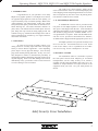
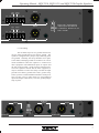
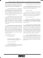
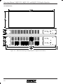
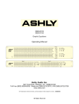
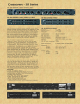
MQX-2310 MQX-1310 MQX-2150 Graphic Equalizer Operating Manual 20 25 31.5 40 50 63 80 100 125 160 200 250 315 400 500 630 800 1K 1.25K 1.6K 2K 2.5K 3.15K 4K 5K 6.3K 8K 10K 12.5K 16K Gain 20K +15(+6) +6 +10 +4 +2 +5 -5 0 -3 -10 -9 0 MQX 2310 Stereo 31 Band Graphic Equalizer Channel 1 EQ Range 40Hz In Out ±6dB ±15dB In Out EQ Range 40Hz In Out ±6dB ±15dB In Out Sig. Clip - -15(-6) Power dB +10 +6 +4 +5 +2 0 0 -3 -9 +15(+6) -5 -10 - -15(-6) 20 25 31.5 40 50 63 80 100 125 160 200 250 315 400 500 630 800 1K 1.25K 1.6K 2K 2.5K 3.15K 4K 5K 6.3K 8K 10K 12.5K 16K 20K 20 25 31.5 40 50 63 80 100 125 160 200 250 315 400 500 630 800 1K 1.25K 1.6K 2K 2.5K 3.15K 4K 5K 6.3K 8K 10K 12.5K 16K 20K Channel 2 Gain Gain Power +6 +4 +2 +15(+6) +10 +5 EQ -5 -10 Range 40Hz Sig. Clip 0 -3 -9 0 MQX 1310 31 Band Graphic Equalizer Sig. Clip In Out ±6dB ±15dB In Out - -15(-6) dB 25 40 63 100 160 250 400 630 1K 1.6K 2.5K 4K 6.3K 10K Gain 16K +5 MQX 2150 Stereo 15 Band Graphic Equalizer 25 +6 +4 +2 +15 +10 0 -10 0 -3 -9 -15 - -5 dB 40 63 100 160 250 400 630 EQ Range Sig. Clip In Out ±6dB ±15dB Channel 1 1K 1.6K 2.5K 4K 6.3K 10K Power Gain 16K + 6 EQ Range +4 Sig. Clip +2 +15 +10 +5 0 0 -3 -9 -5 -10 -15 In Out ±6dB ±15dB dB Channel 2 ASHLY AUDIO INC. 847 Holt Road Webster, NY 14580-9103 Phone: (716) 872-0010 Toll-Free: (800) 828-6308 Fax: (716) 872-0739 Internet: http://www.ashly.com/ Operating Manual - MQX-2310, MQX-1310, and MQX-2150 Graphic Equalizer Table Of Contents 1 INTRODUCTION . . . . . . . . . . . . . . . . . . . . . . . . . . . . . . . . . . . . . . . . . . . . . . . . . . . . . . . 3 2 UNPACKING . . . . . . . . . . . . . . . . . . . . . . . . . . . . . . . . . . . . . . . . . . . . . . . . . . . . . . . . . . . . 3 3 AC POWER REQUIREMENTS . . . . . . . . . . . . . . . . . . . . . . . . . . . . . . . . . . . . . . . . . . . 3 4 SECURITY COVERS . . . . . . . . . . . . . . . . . . . . . . . . . . . . . . . . . . . . . . . . . . . . . . . . . . . . 3 5 CONTROLS . . . . . . . . . . . . . . . . . . . . . . . . . . . . . . . . . . . . . . . . . . . . . . . . . . . . . . . . . . . . . 5.1 Equalization . . . . . . . . . . . . . . . . . . . . . . . . . . . . . . . . . . . . . . . . . . . . . . . . . . . . . . . . . 5.2 Gain . . . . . . . . . . . . . . . . . . . . . . . . . . . . . . . . . . . . . . . . . . . . . . . . . . . . . . . . . . . . . . . . 5.3 EQ In Out Switch . . . . . . . . . . . . . . . . . . . . . . . . . . . . . . . . . . . . . . . . . . . . . . . . . . . . . 5.4 Range Switch . . . . . . . . . . . . . . . . . . . . . . . . . . . . . . . . . . . . . . . . . . . . . . . . . . . . . . . . 5.5 High Pass Filter . . . . . . . . . . . . . . . . . . . . . . . . . . . . . . . . . . . . . . . . . . . . . . . . . . . . . . 5.6 Signal Present Indicator . . . . . . . . . . . . . . . . . . . . . . . . . . . . . . . . . . . . . . . . . . . . . . . 5.7 Clip Indicator . . . . . . . . . . . . . . . . . . . . . . . . . . . . . . . . . . . . . . . . . . . . . . . . . . . . . . . . 5.8 Power Switch . . . . . . . . . . . . . . . . . . . . . . . . . . . . . . . . . . . . . . . . . . . . . . . . . . . . . . . . 6 6 6 6 6 6 6 6 6 6 CONNECTIONS AND CABLES . . . . . . . . . . . . . . . . . . . . . . . . . . . . . . . . . . . . . . . . . . 6.1 Balanced vs Unbalanced Connections . . . . . . . . . . . . . . . . . . . . . . . . . . . . . . . . . . . 6.2 Inputs and Outputs . . . . . . . . . . . . . . . . . . . . . . . . . . . . . . . . . . . . . . . . . . . . . . . . . . . . 6.3 Grounding . . . . . . . . . . . . . . . . . . . . . . . . . . . . . . . . . . . . . . . . . . . . . . . . . . . . . . . . . . . 4 4 4 5 7 TYPICAL APPLICATIONS . . . . . . . . . . . . . . . . . . . . . . . . . . . . . . . . . . . . . . . . . . . . . . 7.1 General Tone Control . . . . . . . . . . . . . . . . . . . . . . . . . . . . . . . . . . . . . . . . . . . . . . . . . 7.2 Feedback Control . . . . . . . . . . . . . . . . . . . . . . . . . . . . . . . . . . . . . . . . . . . . . . . . . . . . . 7.3 Console Channel Equalization . . . . . . . . . . . . . . . . . . . . . . . . . . . . . . . . . . . . . . . . . . 7.4 Large Room Equalization . . . . . . . . . . . . . . . . . . . . . . . . . . . . . . . . . . . . . . . . . . . . . . 6 6 7 7 7 8 DESIGN THEORY . . . . . . . . . . . . . . . . . . . . . . . . . . . . . . . . . . . . . . . . . . . . . . . . . . . . . . . 8 9 TROUBLESHOOTING TIPS . . . . . . . . . . . . . . . . . . . . . . . . . . . . . . . . . . . . . . . . . . . . 10 10 DIMENSIONS . . . . . . . . . . . . . . . . . . . . . . . . . . . . . . . . . . . . . . . . . . . . . . . . . . . . . . . . . . 10 11 SPECIFICATIONS . . . . . . . . . . . . . . . . . . . . . . . . . . . . . . . . . . . . . . . . . . . . . . . . . . . . . 11 12 WARRANTY INFORMATION . . . . . . . . . . . . . . . . . . . . . . . . . . . . . . . . . . . . . . . . . . . 11 13 SCHEMATICS . . . . . . . . . . . . . . . . . . . . . . . . . . . . . . . . . . . . . . . . . . . . . . . . . . . . . . . . . 12 2 Operating Manual - MQX-2310, MQX-1310, and MQX-2150 Graphic Equalizer 1. INTRODUCTION Congratulations on your purchase of an Ashly MQX series graphic equalizer. The MQX series follows our popular GQX equalizers with the same quality you expect from Ashly, only in a smaller package. Where most “mini-equalizers” use 20mm faders, Ashly uses custom built professional quality 25mm faders for maximum resolution and long life. The audio connectors include 1/4" jacks, XLR, and terminal block on both inputs and outputs, along with a provision for lifting input ground. We continue using “Q” enhanced Wein bridge filters and interleaved summing for constant “Q”, low ripple, and minimum filter interaction. The right to any claim against a public carrier can be forfeited if the carrier is not notified promptly and if the shipping carton and packing materials are not available for inspection by the carrier. Save all packing materials until the claim has been settled. 3. AC POWER REQUIREMENTS A standard IEC-320 AC inlet is provided on the rear panel of each MQX equalizer to accept the detachable power cord shipped with the unit. Units distributed within the United States are preselected for 120VAC, 60Hz and should be plugged into a standard NEMA 5-15 3wire grounded AC receptacle. Most units distributed outside the US are preselected and labeled for 240VAC, 50-60Hz and are shipped with the appropriate power cord. 2. UNPACKING As a part of our system of quality control, every Ashly product is carefully inspected before leaving the factory to ensure flawless appearance. After unpacking, please inspect for any physical damage. Save the shipping carton and all packing materials , as they were carefully designed to reduce to minimum the possibility of transportation damage should the unit again require packing and shipping. In the event that damage has occurred, immediately notify your dealer so that a written claim to cover the damages can be initiated. All MQX equalizers will perform normally from 95 to 125 volts AC. An internal line fuse is used. In the event of fuse failure, refer to a qualified service technician for servicing. Power consumption is 18 watts. 4. SECURITY COVERS For installations where it is desirable to protect the front panel controls from tampering or accidental misadjustment, use the Ashly security cover, which is available in both single and double rack space sizes. Installation is simple and does not require removal of the equipment from your rack. See your Ashly dealer for details. Ashly Security Cover Installation 3 Operating Manual - MQX-2310, MQX-1310, and MQX-2150 Graphic Equalizer 20 25 31.5 40 50 63 80 100 125 160 200 250 315 400 500 630 800 1K 1.25K 1.6K 2K 2.5K 20 25 31.5 40 50 63 80 100 125 160 200 250 315 400 500 630 800 1K 1.25K 1.6K 2K 2.5K MQX 2310 Stereo 31 Band Graphic Equalizer 5.3 EQ In/Out Switch 5. CONTROLS 5.1 Equalization The individual equalization faders adjust the boost or cut at each filter frequency. There are 31 of these faders per channel on the MQX-1310 and MQX2310 third octave models, and 15 faders per channel on the MQX-2150 two-thirds octave model. By adjusting a combination of faders, an overall frequency response can be developed and the physical position of the faders will give an approximate visual indication of this response. 5.2 Gain This switches the Graphic Equalization and Gain adjustments. This way, the effect of any equalization can be compared to a “flat” response. This switch does not defeat the High-pass filter. 5.4 Range Switch This switch selects the operating range of the individual equalization faders to either ±15dB or ±6dB. The ±15dB settings should be used when much equalization is needed. The ±6dB setting allows finer resolution on the fader settings. The gain control adjusts the overall gain of the equalizer when the EQ switch is “in”. It is generally used to compensate for level changes due to the equalization process, but can also allow the equalizer to adjust overall system level and gain structure. Overall gain with this control is from +6dB to -∞. 25 40 63 100 160 250 400 630 1K 1.6K 2.5K 4K 6.3K 10K Gain 16K +6 +4 +2 +15 +10 +5 MQX 2150 Stereo 15 Band Graphic Equalizer 0 -10 0 -3 -9 -15 - -5 dB 4 EQ Range Sig. Clip In Out ±6dB ±15dB Channel 1 Operating Manual - MQX-2310, MQX-1310, and MQX-2150 Graphic Equalizer 3.15K 4K 5K 6.3K 8K 10K 12.5K 16K Gain 20K +15(+6) +6 +10 +4 +2 +5 -5 0 -3 -10 -9 0 Channel 1 EQ Range 40Hz Sig. Clip In Out ±6dB ±15dB In Out - -15(-6) Power dB +15(+6) +6 +10 +4 +2 +5 -5 -10 6.3K 8K 10K 12.5K 16K 40Hz In Out ±6dB ±15dB In Out - -15(-6) 5K Range Sig. Clip 0 -3 -9 0 3.15K 4K EQ Gain 20K Channel 2 5.7 Clip Indicator 5.5 High-Pass Filter The red Clip LED turns on when any signal within the audio path exceeds +19dBu. Clipping can be detected at the input stage, gain stage, or at the equalizer output. The high-pass filter can be used to supplement the frequency response achieved by the bandpass filters. It’s function is to “roll off” low end response to eliminate subsonic interference like wind noise, floor rumble, and boomy microphone pops. The high-pass frequency on the 31-band models is fixed at 40Hz with an 18dB/octave slope. The MQX-2150 has an internally switched 20Hz high-pass filter which can be disabled by a qualified service technician. 5.8 Power Switch This front-panel push-button switches the AC power to the unit. The adjacent yellow LED indicates when the unit is powered on. If the yellow LED does not light, check to see if the unit is plugged into a live outlet. If there is still no light, refer the unit to a qualified service technician for possible fuse replacement. 5.6 Signal Present Indicator A green LED indicates when input signal to the equalizer is above -20dBu. EQ or Gain settings have no effect on this indicator, as it only tells you the level of signal applied to the equalizer. 25 40 63 100 160 250 400 630 1K 1.6K 2.5K 4K 6.3K 10K Power Gain 16K +6 +4 +2 +15 +10 +5 0 -3 -9 0 -5 -10 -15 EQ Range Sig. Clip In Out ±6dB ±15dB dB Channel 2 5 Operating Manual - MQX-2310, MQX-1310, and MQX-2150 Graphic Equalizer Balanced Inp Ashly Audio Inc. Made In USA Model MQX-2310 TO REDUCE THE RISK OF ELECTRIC SHOCK DO NOT REMOVE COV ER. NO USER SERVICEABLE PARTS INSIDE. REFER SERVICING TO QUALIFIED SERVICE PERSONNEL. TO REDUCE THE RISK OF FIRE OR EL ECTRIC SHOCK DO NOT EXPOSE THIS EQUIP MENT TO RAIN OR MOI STURE. Balanced Inp AVIS: RISQUE DE CHOC ELECTRIQUE NE PAS OUVRIR. 100-120VAC 50-60Hz 15W 6. CONNECTIONS AND CABLES 6.2 Inputs and Outputs 6.1 Balanced vs. Unbalanced Audio Connections Balanced signal connections are preferred in pro audio applications because of their improved immunity to induced hum and noise. A properly shielded and wired balanced input stage on any product will by design reject most unwanted noise picked up by the cable as well as minimize ground loop problems. Therefore it is always advantageous to use balanced connections when running signal more than ten or fifteen feet, although particularly noisy environments (high RFI, EMI, etc.) may require that even short cabling be balanced. Unbalanced connections are used mostly for short distance, high level signals (0dBu nominal). Most external EMI noise pick-up will be masked under the noise floor of the signal, assuming there is little or no gain following the unbalanced signal. If a gain stage does follow a signal, or if externally sourced noise persists, use balanced connectors. The main advantage of unbalanced connectors is cost, as an unbalanced (tip-sleeve) plug costs less and is easier to wire than a balanced (TRS) plug. Your MQX equalizer is provided with three different connector types. 1/4" TRS (tip-ring-sleeve) phone jacks, three pin XLR connectors, and screw terminals will allow interfacing to most professional audio products. Ashly TRS balanced connections use the tip as (+) and the ring as (-) signal, with sleeve used for ground. Ashly XLR connectors use pin 2 (+) and pin 3 (-) with pin 1 ground. Inputs are active balanced using precision 1% metal film resistors. Outputs are "pseudo-balanced", which means they have balanced impedance with a singleended signal source, and can be wired balanced or unbalanced. When possible, we recommend balanced connections between all components in your system. If inputs are used unbalanced, the signal should be on the (+) connection and the (-) connection must be tied to ground, or signal loss will result. While a mono phone plug used as an unbalanced connection will automatically ground the (-) ring of the jack, XLR and screw terminals will not automatically do this so attention must be given to proper wiring. Balanced Input Ashly Audio Inc. Made In USA Model MQX-2150 100-120VAC 50-60Hz 15W 6 No User Serviceable Parts Inside. To Reduce The Risk Of Fire Or Electric Shock, Do Not Expose This Equipment To Rain Or Moisture Operating Manual - MQX-2310, MQX-1310, and MQX-2150 Graphic Equalizer Output Input Ground (-) Chassis Ground (+) (-) (+) 3 2 1 Channel One Output Input Ground (-) Chassis Ground (+) (-) (+) (-) (+) Input is 20K Ω active balanced. Output may be wired balanced or unbalanced. Maximum in/out level is +22dBu. Channel Two 6.3 Grounding The terminal strip has two ground connections, one for input ground and one for chassis ground. The equalizer is shipped with a jumper strap connecting these two grounds. Normally, this strap should be left in place so the chassis and input grounds are connected. In a rackmount installation where the equalizer is connected to other equipment with unbalanced inputs or outputs and the rack itself provides a good electrical connection between the equalizer chassis and the other equipment, it may be desirable to remove this strap to isolate the input ground from chassis ground and avoid a ground loop. Unless you have such an installation and have a hum problem you can’t solve by other means (ie: using balanced input and output connections), leave the ground jumper strap in place. Output Balanced Input 3 2 Output 1 (+) (-) hannel One Channel Two 7 Operating Manual - MQX-2310, MQX-1310, and MQX-2150 Graphic Equalizer 7. TYPICAL APPLICATIONS 7.1General Tone Control The graphic equalizer is a very useful device for general tone shaping because it is intuitive and easy to adjust. The visual reference provided by the slider position gives an approximate idea of the frequency response generated, with the lower frequencies on the left and higher frequencies on the right. To use the power of an equalizer effectively, you need to translate your idea of the tone you want to produce into a range of numerical frequencies. This is simple after a little practise. Here are a few references which are useful for starting points: Very low bass (the “wind” in a kick drum, almost felt as much as heard -40Hz-80Hz. The low register of a male voice - 200Hz The low register of a female voice - 350Hz Lower midrange (“warmth” frequencies) 400Hz-1KHz Upper midrange (“harshness”, snare drum “bite”, “hot” sound) -2.5KHz-4KHz. Sibilance (“sss” sounds, cymbal “sizzle”) - 8KHz- The combination of a graphic equalizer for tone control and a parametric equalizer (such as the Ashly PQX-571 or PQX-572) for feedback control is highly recommended. 7.3 Console Channel Equalization Many mixing consoles provide only simple equalization for individual channels. If your console has channel inserts, you can patch your graphic equalizer into a channel that’s being used for something important and use it to tailor the sound of this channel exactly the way you want. 7.4 Large Room Equalization Large rooms tend to suffer from multiple reflections with long time delays, long reverberation times, and “ring-modes”, all of which lead to reduced intelligibility and a generally “muddy” sound. As sound travels long distances through the air, high frequencies are attenuated more than low frequencies. In general, large rooms benefit from some low frequency roll-off, high frequency boost, and attenuation of ring mode frequencies. As in the case of feedback control, a graphic equalizer can help reduce an isolated ring-mode or two, but a tunable narrow-band equalizer such as a parametric is more effective here. 8. DESIGN THEORY 15KHz. Try using these starting points as a guide when you want more or less of these types of sounds. Adjust by ear from there. It is always a good idea to remember that a little equalization usually works out much better than a lot, and that there are many audio problems which can not be solved with equalization alone. 7.2 Feedback Control A graphic equalizer can be used to provide some control over moderate feedback problems, but does not have enough flexibility or resolution to handle severe situations. You will achieve the best results when you can eliminate one or two feedback points by setting one or two sliders for no more than a 6dB cut. Often you can find a feedback point by boosting sliders in succession to determine which frequency ranges contain the feedback modes, and then cutting those ranges. Be very careful in this process to avoid explosive feedback and possible system and hearing damage! If you find feedback points with many equalizer bands, remember that cutting every band may not help (all you will do is reduce system gain). 8 While most graphic equalizers look very much the same, there are several important differences in the circuitry used to implement various designs. Perhaps the major differences are in the filters. Some equalizers use a filter made of a capacitor, an inductor, and a resistor, or “RLC” filter. The advantage here is simplicity, but the real disadvantage is the inductor itself. An inductor is a coil of wire with a core of some sort. Inductors are susceptible to hum fields and they are large and expensive. Other equalizers use the same basic approach, but replace the inductor with a “simulated inductor”, which is actually a circuit comprised of an amplifier, a capacitor, and a couple of resistors. This adds parts but is less expensive than a real inductor. The problem with this approach is that simulation is less than ideal; it produces an inductor with high resistive loss resulting in poor curve shape when used in a filter. Another problem with “RLC” designs is that large capacitors must be used for the lower frequency filters, limiting the choice to large, expensive non-polar types or electrolytic capacitors with poor audio performance. Also, Operating Manual - MQX-2310, MQX-1310, and MQX-2150 Graphic Equalizer when this filter type is combined with a potentiometer to adjust the equalization, the resistance of this pot affects the “Q” of the filter so that a little equalization produces a much broader curve than a lot of equalization. The other filter approach is a true bandpass filter. This can be made with no inductors and more practical sized capacitors; the “Q” is easily set and remains constant, and the parts count is reasonable. there are several types of bandpass filters suitable for this job. Ashly uses a “Q” enhanced Wein-bridge filter. Because it is a symmetrical design using matched tuning components, the “Q” is easily set and is very stable. In designing a graphic equalizer, a selection of filter sharpness must be made. More sharpness (higher Q) produces less filter overlap and tighter control over an individual band, but also causes ripple in the frequency response when many filters are boost or cut together to produce a flat response. We feel that the graphic equalizer’s primary use is for “voicing” and tone control, and have set our filter sharpness to produce a maximum of 1dB ripple. The summing system in a graphic equalizer is also important. Since there are a number of filters which combine to produce the overall response, it is important that the filters not interact (they WILL overlap, but the response of one filter should not modify the response of another). Ashly uses an “interleaved” summing system where every other filter uses the same summing amplifier so that adjacent filters never share the same drive and feedback signals. This allows the filters to maintain their natural response. 9. TROUBLESHOOTING TIPS 9.1 No Audio Output Check AC power - is the pilot light on? Check in/out connections - are they reversed? Are you sure you have an input signal? 9.3 Peak Light Flashes or Stays On All the Time If the peak light flashes, the signal level to the equalizer is too high. Turn down the gain. If it is on all the time, disconnect the input and output cables. If it is still on, the unit must be returned for service. 9.4 Distorted Sound This will only be caused by too much signal which will show on the Clip LED. If the LED is not flashing, there is an overload somewhere else in the signal path. Adjust the relative gain of each component in your chain to keep everything at a comfortable level. 9.5 Excessive Hum or Noise Hum will usually be caused by a ground loop between components. Try using the suggested balanced input and output hook-ups if the other pieces of equipment used in conjunction with your equalizer have balanced inputs and outputs. Noise (excessive hiss) can be caused by insufficient drive signal. Make sure you are sending a nominal 0 dBu line level signal to the equalizer. Most noise problems occur because gain is applied to audio signals too late in the chain. For best performance, apply gain to individual source signals as early as possible, like at the mixer input section. As gain increases, it also boosts the noise content of that signal. Any cumulative noise built up in a mixed signal will only be increased by using an equalizer as a gain device, so make every attempt to operate the equalizer with as little gain as possible. Note: Unshielded cables, improperly wired connections, and cable with broken strands (shorts, etc.) are the most common problems. Make sure you use good quality cable with connectors soldered firmly on the correct pin. When in doubt, get in touch with your Ashly dealer, or call the Ashly service department at 800-8286308 ext.125. 9.2 EQ Controls Do Nothing Is the master EQ switch in? The lowest and highest frequency sliders may be beyond the range of the program material or speakers and may produce little or no audible effect. 9 Operating Manual - MQX-2310, MQX-1310, and MQX-2150 Graphic Equalizer 10. DIMENSIONS Figure 10.1: Dimensional Drawings for MQX Equalizers (MQX-2150 Not Shown) 10 Operating Manual - MQX-2310, MQX-1310, and MQX-2150 Graphic Equalizer 11. SPECIFICATIONS Model MQX2150 MQX1310 MQX2310 Input Type . . . . . . . . . . . . . . . . Active Balanced . . . . . . . . . .Active Balanced . . . . . . . . . . Active Balanced Impedance . . . . . . . . . . . . . . . . 20KΩ Balanced . . . . . . . . . . .20KΩ Balanced . . . . . . . . . . 20KΩ Balanced 10KΩ Unbalanced . . . . . . . .10KΩ Unbalanced . . . . . . . . 10KΩ Unbalanced Max. Level . . . . . . . . . . . . . . . . +23dBu . . . . . . . . . . . . . . . . . .+23dBu . . . . . . . . . . . . . . . . . +23dBu Connectors . . . . . . . . . . . . . . . . 1/4" Phone Jack, XLR & Barrier Strip . . . . . . . . . . . . . . . . . . . . . . . . . . . . . . . . Output Type . . . . . . . . . . . . . . . Pseudo-Balanced . . . . . . . . . .Pseudo-Balanced . . . . . . . . . Pseudo-Balanced Impedance . . . . . . . . . . . . . . . . 200Ω Balanced . . . . . . . . . . .200Ω Balanced . . . . . . . . . . . 200Ω Balanced 100Ω Unbalanced . . . . . . . .100Ω Unbalanced . . . . . . . . . 100Ω Unbalanced Max Level . . . . . . . . . . . . . . . . +23dBu . . . . . . . . . . . . . . . . . .+23dBu . . . . . . . . . . . . . . . . . +23dBu Connectors . . . . . . . . . . . . . . . . 1/4" Phone Jack, XLR & Barrier Strip . . . . . . . . . . . . . . . . . . . . . . . . . . . . . . . . . Frequency Response . . . . . . . . ±.25dB 20Hz-20kHz . . . . . . .±.25dB 20Hz-20kHz . . . . . . ±.25dB 20Hz-20kHz THD (20Hz-20KHz) . . . . . . . . <.01%@+20dBu . . . . . . . . . .<.01%@+20dBu . . . . . . . . . . <.01%@+20dBu IM Distortion (SMPTE) . . . . . <.01%@+20dBu . . . . . . . . . .<.01%@+20dBu . . . . . . . . . . <.01%@+20dBu Output Noise (20Hz-20KHz) . <96dBu (unweighted) . . . . . .<-92dBu (unweighted) . . . . . <-92dBu (unweighted) Crosstalk (20Hz-20KHz) . . . . <-90dB . . . . . . . . . . . . . . . . . .NA . . . . . . . . . . . . . . . . . . . . . <-80dB Gain Control . . . . . . . . . . . . . . −∞ to +6dB . . . . . . . . . . . . . .-∞ to +6dB . . . . . . . . . . . . . . . -∞ to +6dB (EQ in, all faders flat, 20Hz-20KHz) Filter Type . . . . . . . . . . . . . . . . Number . . . . . . . . . . . . . . . . . . Bandwidth . . . . . . . . . . . . . . . . Tolerance . . . . . . . . . . . . . . . . . Range . . . . . . . . . . . . . . . . . . . . Constant Q/Wein Bridge . . .Constant Q/Wein Bridge . . . Constant Q/Wein Bridge 2 x 15 . . . . . . . . . . . . . . . . . . .1 x 31 . . . . . . . . . . . . . . . . . . . 2 x 31 2/3 octave . . . . . . . . . . . . . . .1/3 octave . . . . . . . . . . . . . . . 1/3 octave ±3% . . . . . . . . . . . . . . . . . . . .±3% . . . . . . . . . . . . . . . . . . . . ±3% ±6 or ±15dB . . . . . . . . . . . . .±6 or ±15 dB . . . . . . . . . . . . . ±6 or ±15 dB Subsonic Filter . . . . . . . . . . . . 18dB/octave @20Hz . . . . . . .18dB/octave @40Hz . . . . . . 18dB/octave @40Hz (Internally Switchable) AC Voltage Requirements . . . . (240 Available) Power Consumption . . . . . . . . Shipping Weight . . . . . . . . . . . Dimensions . . . . . . . . . . . . . . . 90-125VAC, 50-60Hz . . . . . . 90-125VAC, 50-60Hz . . . . . 95-125VAC, 50-60Hz Notes: 0dBu = 0.775 Vrms - 10W . . . . . . . . . . . . . . . . . . . .10W . . . . . . . . . . . . . . . . . . . . 13W 9 lbs . . . . . . . . . . . . . . . . . . . .9 lbs . . . . . . . . . . . . . . . . . . . . 11 lbs 19"Lx1.75"Hx6"D . . . . . . . .19"Lx1.75"Hx6"D . . . . . . . . 19"Lx3.5"Hx6"D Pseudo-Balanced Output has balanced output impedance with single ended signal 11 Operating Manual - MQX-2310, MQX-1310, and MQX-2150 Graphic Equalizer 12. WARRANTY INFORMATION Thank you for your expression of confidence in Ashly products. The unit you have just purchased is protected by a five-year warranty. To establish the warranty, be sure to fill out and mail the warranty card attached to your product. Fill out the information below for your records. Model Number _______________________________________________________________________________ Serial Number Dealer _________________________________________________________________________ Date of Purchase _____________________________________________________________________________ Dealer’s Address ______________________________________________________________________________ Dealer’s Phone _______________________________________________________________________________ Salesperson __________________________________________________________________________________ 12 Operating Manual - MQX-2310, MQX-1310, and MQX-2150 Graphic Equalizer Schematic Diagram: MQX-2150 13. SCHEMATICS 13 Schematic Diagram: MQX-1310, MQX-2310 Operating Manual - MQX-2310, MQX-1310, and MQX-2150 Graphic Equalizer 14 Operating Manual - MQX-2310, MQX-1310, and MQX-2150 Graphic Equalizer 15 Operating Manual - MQX-2310, MQX-1310, and MQX-2150 Graphic Equalizer ASHLY AUDIO INC. 847 Holt Road Webster, NY 14580-9103 Phone: (716) 872-0010 Fax: (716) 872-0739 Toll Free (800) 828-6308 Internet: http://www.ashly.com/ 1997 by Ashly Audio Corporation. All rights reserved worldwide. Printed in USA 1/97 MQX Rev 1