1
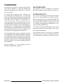
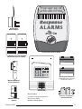
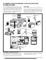
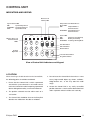
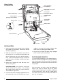
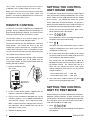
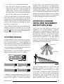
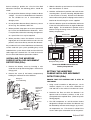
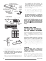
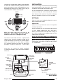
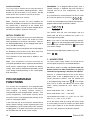
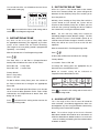
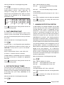
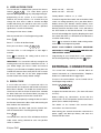
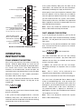
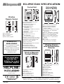
E400 Wirefree
Alarm System
Installation & Operating
Manual
FOREWORD
Your decision to purchase an Eclipse E400 Wirefree
Alarm System represents a major and sensible step
towards total protection of your premises, its contents
and its occupants.
IMPORTANT NOTE
The E400 Wirefree Alarm System complies with
the requirements of BS6799 Class 3 for Wire-Free
Alarms. All components are designed and manufactured
to provide a high standard of security protection and
long, reliable service. In addition, the radio devices are
tested and approved by the Radio Regulatory Division
of the Department of Trade and Industry (DTI) to ensure
that they will not interfere with other radio equipment.
No radio license is required, however, the approved
radio frequency is not protected from interference and
may be withdrawn from use at any time subject to the
DTI giving users an appropriate notice period.
SYSTEM SECURITY
The E400 Wirefree Alarm System is purposely designed
for installation by non-experienced people using only
conventional domestic tools. However, it is essential that
the installer reads and fully understands the advice and
procedures contained in this manual before proceeding
with the installation. This manual should be retained for
future reference.
All components, with the exception of the External
Solar Siren & Strobe, are only suitable for internal use.
This system has been designed to both detect intruders
and act as a strong deterrent to would-be intruders.
Please remember that, given adequate knowledge and
time, it is possible to overcome any alarm system and
we therefore recommend that an Intruder Alarm is used
in conjunction with good physical protection such as
security window and door locks.
The system may be operated remotely from one or
more Remote Controls, or by entering an Access Code
at the Control Unit Keypad.
Care should be taken to ensure that your Remote
Control Unit(s) are not lost as the finder could Disarm
your alarm before you are able to re-code the system.
During installation, it is also important that the
procedures are followed in sequence.
Response
E400 Wirefree Alarm System
CONTENTS
Page No.
FOREWORD
Inside Front Cover
INTRODUCTION AND OVERVIEW
2
PLANNING AND EXTENDING YOUR E400
WIREFREE ALARM SYSTEM
4
CONTROL UNIT
Indicators and Keypad
Location
Installation
Programme Memory
Mains Adaptor and Back-up Battery
5
5
6
6
7
SYSTEM HOUSE CODE
7
REMOTE CONTROL
8
SETTING THE CONTROL UNIT
HOUSE CODE
8
SETTING THE CONTROL UNIT
TO TEST MODE
SYSTEM ZONING
WIREFREE PASSIVE INFRA RED
MOVEMENT DETECTOR(S)
Installation
Setting
WIREFREE MAGNETIC CONTACT
DETECTOR
INSTALLING AND SETTING THE EXTERNAL
SOLAR WIREFREE SIREN & STROBE
Location
Installation
Settings
Initial Power-Up
Page No.
PROGRAMMABLE FUNCTIONS
House Code
Instant/Delay Zone
Exit/Entry Delay Time
Alarm Autostop Time
Part Arm/Zone Omit
Exit/Entry Delay Tones
Jamming Detection System
User Access Code
Siren Code
14
15
15
15
16
16
16
17
17
EXTERNAL CONNECTIONS
17
OPERATING INSTRUCTIONS
Fully Arming the System
Part Arming the System
Disarming the System
Disarming After an Intrusion
Personal Attack Alarm
Battery Monitoring
18
18
19
19
19
19
TESTING THE SYSTEM
20
MAINTENANCE
Control Unit
Solar Siren & Strobe
Rechargeable Batteries
Detectors and Remote Controls
20
20
21
21
ALARM RECORD
21
TROUBLE SHOOTING
22
EXTENDING YOUR E400 WIREFREE
INTRUDER ALARM SYSTEM
24
ACCESSORIES
24
8
9
9
10
10
11
13
13
13
14
YOUR GUARANTEE
E400 SPECIFICATION
Eclipse E400
Inside Back Cover
Back Cover
1
INTRODUCTION AND
OVERVIEW
The E400 Wirefree Alarm System is designed to
allow flexibility in configuring and using the system.
The detectors can be set to operate on any one of
4 Zones, to give an instant alarm or a timed entry
delay. There is no limit to the number of detectors that
can be installed per Zone.
A normally closed, Hard-wired Zone input is also
available on Zone 5.
Part Arm allows only selected detection Zones to be
Armed. For example, for night time protection you can
‘Arm’ the downstairs areas, garage and outbuildings,
whilst allowing you free access to the upstairs areas
without activating your alarm.
The Control Unit is programmed and operated via its
integral keypad. A User Access Code allows general
operation and full access to the programming menu.
Wired output facilities are available for connection to a
Telephone Dialler or Communicator or Hard wired
External Siren & Strobe.
The Control Unit also incorporates a sophisticated
Jamming Detection Circuit with pre-alarm indication.
The E400 Intruder Alarm package contains all the
components necessary to install a complete Intruder
2
Alarm System within your premises. You can increase
your protection by adding additional Wirefree Passive
Infra Red Movement Detectors and Wirefree
Magnetic Contact Detectors either at the time of
initial installation or at a future date. You may also
wish to purchase additional Remote Control Unit(s)
for use by other members of your household. Full
details of other accessories to extend your system
are given on page 24.
The items included in your E400 package are shown
opposite.
EXTENDING THE ECLIPSE
E400 SYSTEM
The following additional accessories are available to
enhance your system and provide further protection
and a higher level of security where required.
Part No
Description
CA2000P
Wirefree Passive Infra Red Detector
CA2000M
Wirefree Magnetic Contact Detector
CA2000R
Remote Control Unit
E100D
Dummy External Siren
Eclipse E400
Control Unit
Mains Adaptor
External Solar Siren & Strobe
2 x Wirefree Passive Infra Red
Movement Detectors (PIRs)
WP1.2-6
ZONE
1
2
3
4
1
2
3
4
5
6
7
8
9
ON
WP1.2-12
0
Rechargeable Batteries
(Supplied fitted in the Control Unit
and Solar Siren & Strobe)
Wirefree Magnetic
Contact Detector
PANIC
ON
OFF
Wirefree Remote
Control
Eclipse E400
Control Unit
Also included:
Installation and Operating Manual
All necessary fixings
Window warning stickers
Detector and Remote
Control Batteries
3
PLANNING AND EXTENDING YOUR ECLIPSE E400
ALARM SYSTEM
For even greater protection you can install as many
Passive Infra Red Movement Detectors and Magnetic
Contact Detectors as and when you require. The E400
Alarm System is designed to give you protection for a
three bedroomed house. Just add additional detectors
where further protection is needed.
PART ARM
Protect either all of your home or just the areas you
choose. For example, for night time protection you can
have downstairs plus the garage and shed ‘ON’ whilst
upstairs is ‘OFF’. This allows you to occupy upstairs
areas without activating your alarm.
Magnetic Contact
Detector
External Solar
Siren & Strobe
PIR Movement
Detector
PIR Movement
Detector
Remote
Control
Magnetic Contact
Detector
ZONE
1
2
3
4
1
2
3
4
5
6
7
8
9
ON
SHED
0
ZONE 4
Control Unit
PIR
Movement
Detector
Back Door
LOUNGE
KITCHEN
ZONE 2
PIR
Movement
Detector
DINNING
ROOM
ZONE 3
ZONE 1
ZONE 2
HALL
ZONE 2
GROUND FLOOR
GARAGE
Magnetic Contact
Detector
PIR Movement
Detector
PLANNING YOUR INSTALLATION
Before attempting to install your E400 Alarm System it is
important to study your security requirements and plan
your installation, including Zoning and Entry/Exit routes.
4
Each property will have its own layout, the diagrams
shown are intended only as a guide.
Eclipse E400
CONTROL UNIT
INDICATORS AND KEYPAD
Detector Low
Battery LED
Tamper/Personal Attack/Zone 5
Alarm LED:
ON:Tamper/PA Zone
Alarm Activation
System Status LED:
ON:System Fully Armed
FLASHING:- System Part Armed
OFF:System Disarmed
FLASHING:- Hard-wired Zone 5
Alarm Activation
ZONE
1
Wirefree Zones 1-4
Alarm Activated
LED's
2
1
3
2
4
ON
Power LED:
ON:Adaptor Power (Normal)
OFF:Battery Power Only
FLASHING:- Test/Programming Mode
3
Part Arm Button
4
5
6
7
8
9
Keypad
Digits 0-9
Full Arm Button
Disarm Button
0
Personal Attack Button
Programme Button
View of Control Unit Indicators and Keypad
LOCATION
When choosing a suitable location for the Control Unit,
the following points should be considered.
1. Ensure that the Control Unit is within a protected
area with the system Armed, ie. an intruder cannot
reach the Control Unit without opening a protected
door or being detected by a movement detector.
2. The position selected must be within reach of a
13A socket.
4. Do not locate the Control Unit closer than 1 metre
to any large metallic object eg. mirrors, radiators,
fridge-freezers etc., as this may affect the radio
range.
5. Locate the Control Unit in any easily accessible
position, between 1.5 and 2 metres above floor level
and in a position where it will be seen each day.
3. The Control Unit should be close to the Entry/Exit
door but not visible from the door or windows.
Eclipse E400
5
View of Inside
of Control Unit
Back-up Battery
Compartment
Hard-wired Siren Tamper
Return Link
Power Jack Socket
Terminal Block
(See page 18 for details)
Memory Link
Control Unit
Anti-Tamper Switch
PCB Protection
Cover
Control Unit
Siren Plug
Ribbon Cable
ON
Control Unit Siren
Screw Cover
Plugs
INSTALLATION
1. Undo the two front cover retaining screws and hinge
the Control Unit cover down. Remove the Control
Unit Back-up Battery.
2. Hold the Control Unit in position and mark the
four fixing holes. A small spirit level placed on top
of the Control Unit will ensure that the panel is
level. Note that the bottom fixings are keyhole
type so the holes should be marked at the top of
the keyhole.
3. Remove the Control Unit and drill four, 4mm
diameter fixing holes.
IMPORTANT NOTE: Do not drill the fixing holes
with the Control Unit in position, as the resulting
dust could seriously affect the system electronics
and invalidate the guarantee.
4. Fully insert the plastic wall plugs supplied and screw
the Control Unit to the wall using the four screws
6
supplied. Be careful when fitting the bottom right
hand screw not to damage the ribbon cable.
5. Ensure that the Control Unit Siren Plug is plugged
into the socket on the circuit board.
PROGRAMME MEMORY
The Control Unit incorporates a ‘Non Volatile Memory’,
which will memorise all programme settings indefinitely
even when all power has been removed. To enable this
facility to operate, the memory link must be set to the
‘ON’ position.
If, for any reason, you wish to erase the programme
memory and reset the Control Unit to the factory
settings, remove all power (mains and Back-up Battery),
set the memory link to ‘OFF’ and then re-apply power.
In all other circumstances the memory link should be
left in the ‘ON’ position.
Eclipse E400
MAINS ADAPTOR AND BACK-UP
BATTERY
Cable Track
7. Close the Control Unit cover and hold it firmly closed
whilst securing the two retaining screws. Fit the screw
cover plugs supplied to cover the retaining screws.
Note: if you accidently trigger the Control Unit AntiTamper Switch whilst closing the cover,
1
Enter
WP1.2-12
2
3 4
to cancel the alarm.
EXTERNAL CONNECTIONS
The Control Unit incorporates a terminal block to
facilitate external connection of a Hard Wired Siren,
Telephone Dialler or a Hard Wired Zone 5 Trigger input.
Alternative Cable
Entry Knockout
Power Supply
Jack Socket
12 Volt 1.2 Ahr
Rechargeable
Back-up Battery
A DC Mains Adaptor and cable and 1.2Ahr rechargeable
Back-up Battery are supplied with the E400 equipment.
The purpose of the battery is to supply emergency
power to the Control Unit in the event of a failure of the
mains supply. The Back-up Battery is capable of
providing emergency power to the Control Unit for a
period of approximately 24 hours and will automatically
recharge on restoration of the supply. To fit the mains
adaptor and battery, proceed as follows.
1. Lead the cable along the cable track or pass the
cable through the knockout in the rear of the casing.
2. Plug the jack plug into the jack socket on the printed
circuit board as shown.
3. Plug the adaptor into a 13A socket.
4. The Control Unit will emit a bleep and the green
power indicator will now illuminate steadily,
indicating that the Control Unit is powered from the
mains supply. (It is normal for the mains adaptor to
appear warm to the touch when in use).
5. To fit the Back-up Battery, place the battery in the
compartment provided and connect the battery
leads red to red (+) and black to black (-).
If any Hard-wired connections are to be made at the
Control Unit it is recommended that these are made
AFTER the initial installation and programming of the
Control Unit.
For details of making external connections to the
Control Unit, see page 17.
SYSTEM HOUSE CODE
In order to prevent any unauthorised attempt to activate
or disarm your system, you must set your system to
accept encrypted radio signals only from your own
detector(s) and Remote Control Unit(s). This is done by
setting a series of two position miniature switches in the
detectors and Remote Control Unit(s) to a special
combination (House Code) selected by yourself and
programming the Control Unit to recognise only this
House Code combination.
IMPORTANT: In order for all detectors, Remote
Control Unit(s) and accessories to communicate
with the Control Unit, it is essential that the same
House Code combination is used for all components.
(Except the Solar Siren & Strobe which has a separate
Siren Code).
ON
6. In the event of mains failure the green power
indicator will now extinguish warning that the
Control Unit is powered by battery only.
Note: pressing any button on the Control Unit
Keypad, or Arming/Disarming from the Remote
Control will cause the power indicator to reilluminate for approximately 10 seconds and then
extinguish whilst on Back-up Battery power.
Eclipse E400
e.g.
1
2
3
4
5
6
7
8
9
10
Switch 1
set to the
ON position
House Code
(Always change from
the factory setting)
Note: Miniature switches 9 and 10 control the system
zones and DO NOT form part of the House Code
Inside your Remote Control(s) and detectors you will
find a series of two position miniature switches. Your
7
House Code is set up by moving each of the first 8 switches
(numbered 1-8) to a random sequence of ‘ON’ or ‘OFF’.
Note: when setting the miniature switches in each item
of equipment, ensure that each switch ‘clicks’ into
position. Use the tip of a ball point pen or a small screw
driver to move each switch in turn.
REMOTE CONTROL
One Remote Control Unit is supplied in the standard E400
package. However, additional Remote Control Unit(s) can
be purchased separately, if required. The Remote Control
Unit(s) are used to Fully Arm or Disarm the system.
The Remote Control is also used to initially set the
Control Unit’s House Code and Siren Code.
The Remote Control Unit also incorporates a personal
attack button. This sounds the alarm at any time
whether the system is Armed or not. Just press ‘Panic’
and the alarm will sound. If this is activated by mistake
you can cancel the alarm by pressing and releasing the
‘OFF’ button on the Remote Control.
Any number of Remote Control Unit(s) can be used with
your system, providing they are all coded with the
system House Code. To set the House Code and fit the
battery, proceed as follows.
1. Remove the battery cover
with a coin.
PANIC
ON
OFF
PANIC
ON
OFF
House Code
Dip Switches
ON
1
2
3
4
5
6
7
To enable the Control Unit to receive the radio signals
from your Remote Control(s) and detectors, the system
House Code must be programmed into the Control
Unit’s memory. The Control Unit learns the system
House Code from the Remote Control. Ensure that a
battery has been fitted and a House Code has been set
in the Remote Control and then proceed as follows:1. Ensure that only the Control Unit’s green mains
power indicator LED is illuminated.
2. Enter
1
2
3 4
The Control Unit is now in Test/Programming mode.
The power LED will now be flashing.
3. Enter
1
The Zones 1-4 LEDs will illuminate (unless a House
Code has already been set in which case the LEDs
will indicate the code set).
4. To set the Control Unit House Code, (or to change
the House Code to the new code) simply press the
‘OFF’ button on your Remote Control.
The Control Unit will acknowledge the signal by
bleeping twice and memorise the House Code set in
the Remote Control. The Control Units row of 8
LEDs will now indicate the House Code switch
setting selected for each switch 1-8 in the Remote
Control as follows:House Code switch ‘ON’ = LED ‘ON’
House Code switch ‘OFF’ = LED ‘OFF’
5. Once the House Code has been set, press
twice to exit Test/Programming mode.
8
2. Fit the 12 Volt Alkaline battery supplied with the
negative (-) towards the battery spring.
3. Using a small screwdriver or ball-point pen, set the
miniature switches 1-8 to a random combination of
‘ON’ and ‘OFF’ settings. This is your House Code.
Make a careful note of the setting of each switch as
this information will be needed when you set up
other items in your system.
4. Replace the battery cover.
8
SETTING THE CONTROL
UNIT HOUSE CODE
SETTING THE CONTROL
UNIT TO TEST MODE
Before installing Passive Infra Red Movement Detectors,
Magnetic Contact Detectors or other accessories you
should set the Control Unit to Test/Programming mode.
This will help to ensure that the correct House Code is
used and to establish the radio range.
1. Enter
1
2
3 4
The Control Unit will emit two bleeps and the power
LED will flash.
Eclipse E400
2. The system is now in Test/Programming mode.
3. Now, each time the Control Unit receives a valid
radio signal from a detector or Remote Control, the
Control Unit will emit a two-tone alarm for
approximately 3 seconds and the associated Zone
LED will illuminate. To clear the Zone LED indicator,
press the ‘OFF’ button on your Remote Control.
To test the radio range of the Control Unit’s receiver,
press and release the ‘Panic’ button on the Remote
Control from in and around the property and from all
locations where you plan to install the detectors and
check that the Control Unit acknowledges the signals
by emitting a two tone alarm.
The Control Unit should be left in Test mode whilst the
detectors and other accessories are set up and
installed. However, if you wish to exit the Test mode,
press the
button. The Unit will emit two bleeps and
the power LED will illuminate steadily.
SYSTEM ZONING
The E400 detectors can be set to operate on any one of
four Zones. There is no limit to the number of detectors
that can be installed on a Zone, although we
recommend that only one detector is installed per Zone
for ease of alarm verification. Alternatively, where more
than four detectors are installed, group all the detectors
in one area or room on the same Zone.
on alarm) circuit. This is referred to as Zone 5 and is
indicated at the Control Unit on the Tamper/Personal
Attack/Zone 5 LED (LED flashing). The Hard-wired Zone
should be wired across terminals 10 and 11 on the
Control Unit terminal block, in place of the factory fitted
link. The Tamper/Personal Attack Zone also monitors the
detector and Control Unit Tamper Circuits, ie. Control
Unit front and rear Tamper switches, Jamming Detection
and, (where fitted), Hard-wired siren tamper return.
WIREFREE PASSIVE
INFRA RED MOVEMENT
DETECTORS (PIRs)
Two Passive Infra Red Movement Detectors are
supplied in the standard package.
However,
additional Passive Infra Red Movement Detectors can
be purchased separately, if required. Passive Infra
Red Movement Detectors are designed to detect
movement within a protected area. The detector
element detects differences in Infra Red radiation
when a person moves within the protected area. If
movement is detected, a radio signal is transmitted to
the Control Unit to activate the alarm.
110° angle
Zone selection is set on each detector using the two
position miniature switches 9 and 10 as follows:-
60° angle
1
2
3
4
5
6
7
8
9
2-2.5m
ON
10
House Code
Zone Code
ON
1
Up to 6m at 110° and 12m at 60°
ON
2
3
4
5
6
7
8
9
10
1
2
3
4
5
6
7
Zone 1
ON
1
8
9
10
Zone 2
ON
2
3
4
5
6
7
8
9
10
Zone 3
1
2
3
4
5
6
7
8
9
10
Zone 4
In addition to a Radio Detection Alarm input on Zones
1-4, facilities are available on the Control Unit terminal
block to also Hard-wire a normally closed (open
Eclipse E400
The recommended position for a Passive Infra Red
Movement Detector is in the corner of a room
mounted between 2 and 2.5 metres from the floor.
At this height, the detector will detect movement up
to 6 metres at 110° and 12 metres at 60° depending
on adjustment. Also, in this position, the 110°/60°
fan-shaped detection patterns can normally offer
greater protection than mounting on a flat wall.
9
Before selecting a position for a Passive Infra Red
Movement Detector the following points should be
noted:
1. Do not position detector facing a window or direct
sunlight. Passive Infra Red Movement Detectors
are not suitable for use in conservatories or
draughty areas.
2. Do not position detector directly above any source
of heat, eg. fire, radiators, boiler etc.
3. Where possible, keep pets out of areas protected
by Passive Infra Red Movement Detectors. If this
is not possible, alternative mounting arrangements
or a special Pet Lens may be required.
4. Where possible, mount the detector so that the
logical path of an intruder would cut across the fan
patterns rather than directly towards the detector.
Any number of Passive Infra Red Movement Detectors
can be used with your system, providing they are all
coded with the system House Code and are within the
radio range of the Control Unit. To install and set the
Passive Infra Red Detector, proceed as follows.
INSTALLING THE WIREFREE
PASSIVE INFRA RED MOVEMENT
DETECTORS (PIRs)
1. Remove the battery cover by inserting a coin
under the cover lip and twisting open. Remove the
fixings pack.
2. Remove the screw (in the battery compartment)
holding the wall bracket to the detector.
TOP
Fixings for
Corner Mounting
TOP
Pulse Count
Detection
Switch on
Side
DOWN = 1
pulse
detection
10
4. Hold the wall bracket in position and mark the two
mounting holes. (If corner mounting, drill pilot holes
in the chamfers as shown). Drill two 4mm diameter
holes and insert the plastic wall plugs and screw the
bracket to the wall using the screws supplied.
5. Offer the detector up to the wall bracket and locate
it into one of the bracket slots to angle the detector
down slightly. Fix the detector in position on the
bracket using the fixing screw at the rear of the
battery compartment.
House Code
Anti
Tamper
Switch
ON
1
2
3
4
5
6
7
8
9
10
ZONE SETTING
Switches 9 + 10
ON
1
2
3
4
5
6
7
8
9
10
Backplate Fixing Screw
SW9 SW10 Zone
ON
ON
1
ON
OFF
2
OFF
ON
3
OFF
OFF
4
View inside PIR Movement Detector
Battery Compartment
SETTING THE WIREFREE
PASSIVE INFRA RED MOVEMENT
DETECTORS (PIRs)
ENSURE THAT THE CONTROL UNIT IS STILL IN
TEST MODE.
UP = 2
pulse
detection
Fixings for
Surface Mounting
3. Slide the bracket up and remove the wall bracket
from the detector as shown.
1. Using a small screwdriver or ball-point pen, set the
miniature switches 1-8 to the same combination of
‘ON’ and ‘OFF’ as the switches in the Remote Control.
2. Determine the Zone on which the detector is to
operate and set miniature switches 9 and 10 to
correspond to the required Zone. (Refer to System
Zoning page 9).
3. The PIR incorporates an anti false-alarm feature
designed to compensate where the detector may
be affected by environmental changes, eg. insects,
air temperature, etc. This feature is called ‘Pulse
Count’ and may be selected for one or two pulses.
Eclipse E400
The recommended Pulse Count is one. In cases of
extreme environmental problems or if unattributable
false alarms are experienced, it may be necessary
to select two Pulse Count detection.
Note: The higher the Pulse Count, the more
paces an intruder will have to move before
triggering the alarm.
To select the required Pulse Count move the switch
on the side of the detector:
UP = Two Pulse Detection
DOWN = One Pulse Detection
4. Fit the 9 Volt Alkaline battery supplied to the battery
terminals, but do not replace the battery cover.
Note: As soon as the battery is connected, a two
tone Alarm will be emitted from the Control Unit
siren for 3 seconds and the Tamper/PA Zone LED
will illuminate. This confirms that the House Code
is correct and that the detector is within radio
range of the Control Unit.
5. After the battery has been connected for approx.
40 seconds, the Infra Red Movement Detector will
become active causing the LED above the
detector window to flash every time movement is
detected. Where two Pulse Count detection has
been selected, the LED will be dim on the first
detection and brighter on the second.
The Control Unit will also emit a 3 second alarm
tone each time the detector senses movement and
the appropriate Zone LED will be illuminated to
confirm the Zone selected.
6. By walking into the protected area the detector will
now be triggered each time the detector senses
movement. If necessary re-adjust the detection
distance by angling the detector up or down on its
wall bracket.
7. Replace the battery cover on the detector.
Note: When the detector is fully installed, ie.
battery cover is refitted, the Unit will not detect
movement for approx. 40 seconds after each
activation. In normal operation, with the battery
cover on, the red LED, above the detector window,
will NOT illuminate upon detection of movement.
Leave the Control Unit in Test mode and proceed to
install your remaining detectors.
Eclipse E400
WIREFREE MAGNETIC
CONTACT DETECTOR
One Magnetic Contact Detector is supplied in E400
package. However, additional Magnetic Contact
Detectors can be purchased separately if required. Any
number of Magnetic Contact Detectors can be used
with your system providing they are all coded with the
system House Code and are within radio range of the
Control Unit. Magnetic Contact Detectors can be fitted
to protect doors or windows, as required.
Before fixing the detector to a metal door/window
check the radio range as previously described. Under
exceptional circumstances it may be necessary to
space the magnet/detector off the metal surface using
a plastic or wooden spacer to achieve the necessary
radio range.
To install the detector, set the House Code and fit the
battery, proceed as follows:
ENSURE THAT THE CONTROL UNIT IS STILL IN
TEST MODE
1. Remove the battery cover by sliding and lifting off.
Do not use a screw driver to lever off.
2. Remove the battery holder by carefully tilting up
the end and sliding the connectors off of the
printed circuit board.
3. Fix the detector and magnet to the opening using
either the double sided tape OR screws provided.
When using the screws ensure that the small
countersunk screw is used within the battery
compartment.
Mount the magnet to the door and the detector to
the door frame (or vice versa, if necessary).
Ensure that the arrows on the magnet and
detector are pointing towards each other and that
the gap between the detector and the magnet is
less than 5mm.
4. Using a ball-point pen, set the miniature switches
1-8 to the same combination of ‘ON’ and ‘OFF’ as
the switches in the Remote Control.
5. Determine the Zone on which the detector is to
operate and set miniature switches 9 and 10 to
correspond to the required Zone. (Refer to system
Zoning page 9).
11
Slide Open and Lift Off
Do Not Use A Screw Driver
Tilt and
remove
battery
holder and
insert two
batteries
Raised Head Screw,
Key-hole Slot Fixing
Double Sided Tape
OR Screw Fixing
Battery
Connector
Small Counter-sunk
Screw Fixing
Location of key-hole
screw (underside)
Hole for mounting
screw
11mm
8mm
Printed
circuit board
Anti-tamper
switch
ON
1
2
3
4
5
6
7
8
9
10
House Code
ZONE SETTING
Switches 9 + 10
SW9 SW10 Zone
Magnet
ON
ON
1
ON
OFF
2
OFF
ON
3
OFF
OFF
4
8. Refit the battery cover by placing it over the
batteries and sliding it on.
9. Test the operation by opening the door/window.
The LED on the detector will light for approx.
1 second and then extinguish each time the magnet
is parted from the detector.
The Control Unit will also emit a 3 second alarm
tone each time the detector is operated and the
appropriate Zone LED will be illuminated to
confirm the Zone selected.
Once you have completed installing all your
detectors, take the Control Unit out of Test mode
by pressing the
button. The Control Unit will
emit 2 bleeps and the Power LED will illuminate
steadily.
INSTALLING AND
SETTING THE EXTERNAL
SOLAR SIREN & STROBE
The Solar Siren & Strobe Unit should be fitted to the
outside of the building in a position that is clearly
visible and at a height which is relatively inaccessible
to an intruder.
Detector
Alternative
Mounting
6. Slide the batteries supplied into the battery holder,
ensuring that the positive (+) side is uppermost on
each battery as it is installed.
7. Carefully refit the battery holder into the detector
ensuring that the spring connectors slide onto
either side of the circuit board.
Note: As soon as the battery holder is connected, the
Control Unit will emit a two tone alarm for 3 seconds
12
and the Tamper/PA Zone LED will illuminate. This
confirms that the House Code is correct and that the
detector is within radio range of the Control Unit.
The Solar Siren & Strobe incorporates a solar panel
which will maintain a charge to the integral 6 Volt
1.2Ahr sealed lead acid rechargeable battery during
daylight hours. During the night, a negligible amount
of energy is released by the rechargeable battery
to operate the Siren & Strobe. The Solar Siren &
Strobe is self maintainable during darkness and
long winter periods.
LOCATION
To provide the optimum amount of daylight to the
Solar Panel, you should ideally mount the Solar Siren
& Strobe on a south facing wall. However, an easterly
or westerly position will suffice.
Although the Solar Siren & Strobe is designed to work on
any aspect wall, for optimum performance you should
refrain from siting the Unit on a north facing wall where
possible. Shadows cast by neighbouring walls, trees and
Eclipse E400
roof overhangs should also be avoided. Where applicable,
the Solar Siren & Strobe should be positioned a minimum
of twice the width of the eaves overhang below the eaves.
Remember that in winter the sun is lower in the sky and you
should avoid winter shadows where possible.
NORTH
Avoid if
possible
INSTALLATION
Remove the holding screw from the base of the housing
and carefully hinge off the front cover. All electronic
components are housed within the front cover.
Use the rear backplate as a template to mark the position
of the four fixing holes on the external wall. Drill four
5mm diameter holes and insert the plastic wall plugs.
Mount the backplate using the four screws provided.
SETTINGS
EAST
WEST
Undo the three screws holding the dip switch cover in
place and remove the cover.
SIREN CODE
Under the cover you will find a series of two position
miniature dip switches.
SOUTH
Note: The Solar Panel does not have to be
mounted in direct sunlight, but does require a
minimum of two hours of daylight each day.
The Solar Siren & Strobe contains a sophisticated
radio receiver. However, reception of radio signals
can be affected by the presence of metallic objects
within the vicinity of the Solar Siren & Strobe.
It is therefore important to mount the Solar Siren
& Strobe a minimum distance of 1 metre radius
Using a ball-point pen set the miniature dip switches
1-8 to a random sequence of ‘ON’s’ and ‘OFF’s’.
Make a note of the Siren Code dip switch settings as
this will be needed when programming the Siren
Code into the Control Unit.
DO NOT SET THE SIREN CODE TO THE HOUSE CODE
USED IN THE DETECTORS/REMOTE CONTROLS.
Note: When the Siren & Strobe is viewed as
shown below (solar panel at top) the dip switches
are ‘upside down’.
Alarm Duration dip switch 9
ON
away from any external or internal metalwork,
ie. external drain pipes, gutters and internal radiators,
mirrors etc.
1
2
3
4
5
6
7
8
9
Siren Code
(Always change from the factory setting)
Solar Panel
Receiver
Aerial
Front cover
locating tabs
Dip switch
cover
Anti-Tamper
switch
P2
P3
3
4
5
6
7
8
9
Eclipse E400
2
Siren
ON
9 Volt PP3 initial
power up battery
1
6 Volt 1.2Ahr
rechargeable
battery
7.5 Volt DC
charging adaptor
input
House Code
dip switches 1-8
Printed circuit
board enclosure
Strobe Lamp
PCB
Alarm duration
dip switch 9
View of inside Solar
Siren & Strobe
13
ALARM DURATION
This is the maximum length of time that the Solar Siren &
Strobe alarm will sound for, following activation. Alarm
duration can be set for either 3 or 15 minutes. Set dip
switch 9 ‘OFF’ for 3 minutes or ‘ON’ for 15 minutes.
Refit the dip switch cover securely.
Note: Following activation into alarm condition the
Solar Siren & Strobe will continue to sound until either
the Control Unit is disarmed, or the Control Unit
Autostop time expires, or until the Siren & Strobe Alarm
Duration Time expires; whichever occurs first.
INITIAL POWER-UP
Once you have completed setting your Siren Code and
Alarm Duration Time, connect the 9 Volt PP3 initial
Power-up Battery to the clip-on connectors. Connect
the Rechargeable Battery to the charging leads red to
red (+) and black to black (-).
Hinge the front cover locating tabs over the top edge of
the backplate, push the base of the Siren cover into
place and secure with the lower fixing screw.
The installation of your Solar Siren & Strobe is now
complete.
Note: Once the batteries have been connected, the
unit will be operational and it is important that the Solar
Panel receives sufficient light to maintain the battery
charge. Also, the Unit should not be repeatedly set into
alarm during installation/testing as this could rapidly
drain the battery.
PROGRAMMABLE
FUNCTIONS
The Control Unit incorporates nine programmable
functions which are selected and set via the Control
Unit’s keypad.
A factory ‘Default’ setting is
incorporated for each programmable function. The
system incorporates a non-volatile memory which
memorises all the user programmable settings in the
event of a total power down.
In the event that you wish to revert the Control Unit to
factory ‘Default’ settings, remove all power (mains and
Back-up Battery), set the memory link to ‘OFF’ and then
re-apply power. In all other circumstances the memory
link should be left ‘ON’ for full system security.
14
IMPORTANT: As all programmable functions have a
‘Default’ setting it is important that each function is
selected and set to your requirements on initial
installation.
The Control Unit has an initial ‘Default’ User Access Code
(the code that operates the system) of 1 2 3 4 .
To enter the Test/Programming mode and change each
programmable function, proceed as follows:
Enter
1
2
3 4
or Current User
Access Code
The Control Unit will emit two bleeps and the
Power LED will flash to indicate the system is in
Test/Programming mode.
Note: If you make an error when entering your settings,
press
once to exit the programming function then
enter the function number followed by
and re-enter
your correct settings.
To exit the Test/Programming mode at any time
Enter
1. HOUSE CODE
The House Code setting enables the Control Unit to
receive signals only from its associated detectors.
The House Code is usually self-learned from the
Remote Control on initial installation (see page 8)
and further programming is therefore not required.
However, if a Remote Control is lost or the House
Code needs to be re-programmed for any other
reason, proceed as follows:- with the Control Unit
in Test/Programming mode enter 1
. The Control
Unit’s row of 8 LEDs will indicate the House Code
switch setting selected for each switch 1-8 as
follows:House Code Switch ‘ON’ = LED ‘ON’
House Code Switch ‘OFF’ = LED ‘OFF’
Factory Default House Code 1, 2, 3, 4, ‘ON’ - 5, 6, 7, 8, ‘OFF’;
LEDs 1, 2, 3, 4, ‘ON’ - 5, 6, 7, 8, ‘OFF’.
To set the House Code (or change the House Code
to a new code), ensure that a battery has been fitted
and a House Code set in the Remote Control then
press the ‘OFF’ button on the Remote Control.
Eclipse E400
The Control Unit LEDs 1-8 will indicate the new House
Code switch setting eg.
ZONE
1
2
3
4
ON
ON
1
2
3
4
5
6
7
1
2
3
4
5
6
7
8
9
8
0
Press
to memorise the House Code setting and to
revert to the Test/Programming mode.
2. INSTANT/DELAY ZONE
Any Zone can be set to give an Entry Delay when
the appropriate detector(s) are triggered, eg. to allow
access to the Control Unit for manual Disarming.
(The length of the entry delay period is programmed
separately - see 3 below).
With the Control Unit in Test/Programming mode
Enter 2
The Zone LEDs 1-4 and Zone 5 (Tamper/Personal
Attack) LED will indicate the status of each Zone:-
3. EXIT/ENTRY DELAY TIME
When the system is Fully Armed either at the Control
Unit or via a Remote Control, the system will ignore all
detectors for the Exit/Entry Delay time, to allow you to
leave the premises.
Similarly, when entering an Entry Delay Zone with the
system Armed or Part Armed, the system will be
inactive for the Exit/Entry Delay time to allow you time
to Disarm the system by entering your Access Code at
the Control Unit, or using the Remote Control.
Note: The Exit and Entry Delay times cannot be
individually programmed to different settings. The Exit
delay when the system is Part Armed is preset to 30
seconds and cannot be changed. However, the Entry
Delay time will be the same as that set for Full Arm
operation.
With the Control Unit in Test/Programming mode
Enter 3
A Zone LED will illuminate to indicate the setting:Factory default:30 seconds - Zone 3 LED ‘ON’
Zone LED ‘ON’ = Delay Zone
Zone LED ‘OFF’ = Instant Zone
To change the setting, press the appropriate key to
illuminate the associated Zone LED:-
Factory default:-
Note: 50 seconds setting will be indicated on
Tamper/Personal Attack/Zone 5 LED.
Zone 1 Entry Delay
Zone 1 LED ‘ON’
To add or delete a Delay Zone, press the number of
the Zone to illuminate or extinguish the appropriate
Zone LED.
Note: The Hard-wired input Zone (Zone 5) can also be
set for instant or delay operation and its status will be
indicated by the Tamper/Personal Attack Zone LED
being ‘ON’ or ‘OFF’.
Press
to memorise the setting and to revert to the
Test/Programming mode.
Press
Exit/Entry
Time
1
2
3
4
5
10s 20s 30s 40s 50s
Enter
to memorise the setting and to revert to the
Test/Programming mode.
4. ALARM AUTOSTOP TIME
This is the length of time that the alarm will sound for
when activated. (If accidently triggered, the alarm can
be stopped at any time using the Remote Control or by
Disarming at the Control Unit keypad).
Note: The maximum length of time that the External
Solar Siren & Strobe will sound for when activated is set
within the Solar Siren & Strobe to either 3 or 15 minutes
- refer to ‘Installing and Setting the External Solar Siren
& Strobe’ for details.
Eclipse E400
15
With the Control Unit in Test/Programming mode
Zone 1 LED will indicate the setting:-
Enter 4
LED ‘ON’ - constant Exit/Intermittent Entry bleep
tone selected
LED ‘OFF’ - semi silent Exit/Entry bleeps selected
A Zone LED will illuminate to indicate the setting:(factory default 3 minutes - Zone 3 LED ‘ON’). To
change the setting press the appropriate key to
illuminate the associated Zone LED:- (Note: 10 minutes
setting will be indicated on the Tamper/Personal
Attack/Zone 5 LED).
Press
Alarm
Time
1
2
3
4
5
1
2
3
5
10
Factory default:Constant Exit/Intermittent Entry bleep tone ‘ON’ - Zone 1
LED ‘ON’
Press
1 as required to select the delay tone required
Press
to memorise the setting and revert to the
Test/Programming mode.
minute minutes minutes minutes minutes
7. JAMMING DETECTION SYSTEM
Press
to memorise the setting and to revert to the
Test/Programming mode.
5. PART ARM/ZONE OMIT
Any of the Zones 1-5 can be omitted (ie. made in-active)
when the system is Part Armed. This will enable you to
Arm only the selected (active) Zones when you Part Arm
the system.
With the Control Unit in Test/Programming mode
Enter 5
The Zone LEDs 1- 4 and Tamper/Personal Attack/Zone
5 LED will illuminate to indicate the Zones which are
OMITTED (in-active) when the system is Part Armed:Factory default:Zones 3 and 4 omitted - Zones 3 and 4 LEDs ‘ON’
(ie. Zones 1, 2 and 5 are Active in Part Arm)
In order to detect any attempts to illegally Jam the radio
channel used with your alarm system a sophisticated
Jamming Detection system is incorporated into the
Control Unit. If this feature is selected and the radio
channel is continuously jammed for more than 30
seconds, when the system is Armed or Part Armed, the
Control Unit sounder will emit a pre-alarm series of
rapid bleeps for 5 seconds. If the Jamming continues
for a further 10 seconds or more, a Full Alarm will occur
indicated by the Internal and External Alarms sounding
and the Tamper/Personal Attack Zone LED illuminating.
The Jamming Detection circuit is designed to scan for
jamming signals. However, it is possible that it may
detect other local radio interference operating legally or
illegally on the same frequency. If it is planned to
operate the jamming detection feature we recommend
that the system is monitored for false jamming alarms
for at least 2 weeks prior to leaving the Jamming Detect
function on permanently.
To add or delete an omitted Zone, press the number of
the Zone to illuminate or extinguish the appropriate
Zone LED.
With the Control Unit in Test/Programming mode
Press
to memorise the setting and to revert to the
Test/Programming mode.
Zone 1 LED will indicate the setting:-
6. EXIT/ENTRY DELAY TONES
During the Exit/Entry delay periods the Control Unit may
be set to either emit a constant Exit/Intermittent Entry
bleep tone or two short bleeps at the beginning and end
of the delay time (semi silent), depending on the
programming.
With the Control Unit in Test/Programming mode
Enter
7
LED ‘OFF’ - Jamming Detection system ‘OFF’
LED ‘ON’ - Jamming Detection system ‘ON’
Factory default:Jamming Detection ‘OFF’, Zone 1 LED ‘OFF’
Press 1 as required to select the Jamming Detection
‘ON’/‘OFF’
Press
to memorise the setting and revert to the
Test/Programming mode.
Enter 6
16
Eclipse E400
8. USER ACCESS CODE
The Control Unit is supplied with a preset User Access
Code of 1 2 3 4 . This code allows general
operation (Arming/Disarming etc) and programming/reprogramming of the system at the Control Unit.
However, for security reasons, it is essential that you
change the User Access Code to another four-digit
number which only you and other users of the system
will know and use (usually a number with a personal
significance is easier to remember).
To change the User Access Code:With the Control Unit in Test/Programming mode
Enter 8
?
Factory default:- switches 1, 3, 5, 7 ‘ON’
To enter/change the Siren Code, refer to the Siren Code
switch 1-8 settings previously set in your Solar Siren &
Strobe, remove your Remote Control’s battery cover
and temporarily reset the miniature switches 1-8 in the
Remote Control to the Siren Code. Press and release
the ‘OFF’ button on the Remote Control. The Control
Unit will acknowledge the signal by bleeping twice and
the Control Unit LEDs 1-8 will illuminate to indicate the
new Siren Code setting.
Press
to memorise the Siren Code setting and to
revert to the Test/Programming mode.
Zones 1 - 4 LEDs will be illuminated.
Enter your new Access Code ?
Switch set ‘ON’ - LED ‘ON’
Switch set ‘OFF’ - LED ‘OFF’
?
?
The Zone LEDs 1-4 will extinguish as each digit is
entered.
RESET YOUR REMOTE CONTROL MINIATURE
SWITCHES TO YOUR HOUSE CODE AND REPLACE
THE BATTERY COVER.
Press
to memorise the setting and to revert to
Test/Programming mode.
Programming of your Control Unit is now complete.
Exit Test/Programming mode by pressing
again.
IMPORTANT: The Control Unit will only recognise the
entering of the new User Access Code from now on. If
you should forget your Access Code and need to
change it, you will need to completely power down the
Control Unit and reset the memory link to ‘OFF’ to revert
the Access Code and all the other programmable
functions back to the factory default settings.
9. SIREN CODE
A small radio transmitter is incorporated within the
E400 Control Unit to operate and control the External
Solar Siren & Strobe. To enable the Control Unit to
communicate with the External Solar Siren & Strobe
the Siren Code set in the External Siren (see page 13)
needs to be programmed into the Control Unit.
This is done by temporarily resetting the House Code in
the Remote Control to the Siren Code and teaching the
Siren Code to the Control Unit.
To programme the Siren Code into the Control Unit,
with the Control Unit in Test/Programming mode
Enter 0
EXTERNAL CONNECTIONS
The Control Unit incorporates a terminal block for
external connection of a Hard-wired Siren, Telephone
Dialler or a Hard-wired Zone 5 trigger input.
To access the terminal block, set the Control Unit to
Test/Programming mode by
Entering ?
?
?
?
Access Code
and open the Control Unit cover. (The alarm will sound
on ‘Test’).
Before making any connections, ensure that the
memory link is in the ’ON’ position and then remove the
power (mains and Back-up Battery).
Full details of the Control Unit terminal block
connections are shown overleaf.
After making your external connections reconnect the
power supply and Back-up Battery and close the
Control Unit front cover.
The Control Unit’s row of 8 LEDs will indicate the Siren
Code switch setting selected for each two position
switch as follows:-
Eclipse E400
17
1
POWER –
2
POWER +
3
N.O.
4
COM
5
N.C.
6
SIREN (+)
7
COM (–)
8
TAMPER
9
COM
10
WIRE ZONE
11
BATTERY –
12
BATTERY +
12 Vold DC
Permanent Supply Output
Latching Relay
Change-over Contacts
12 Volt DC
Output On Alarm
Hard-wired Siren Tamper Circuit/
Negative Tamper Return
(Siren Tamper Return Link must be set to
the 'ON' position when connection made)
Hard-wired Zone 5 Input
(Remove Link and Wire In
Normally Closed Circuit)
Factory
Link
12 Volt DC
Permanent Supply Input
(Not used in the UK)
Details of Control Unit Terminal Block
If the system Exit/Entry Delay tone has been set for
‘Semi Silent’, the Control Unit will emit two bleeps,
followed by two bleeps on expiry of the Exit time.
All occupants must leave the premises before the Exit
time has expired. If for any reason you are unable to
leave the premises before the Exit time has expired,
you will need to Disarm the system, then Re-Arm.
Failure to do so will cause a Full Alarm if any protected
door is opened or movement is detected by a Passive
Infra Red Movement Detector.
Note: When Fully Armed, the Control Unit ‘System
Status’ LED will be constantly illuminated.
PART ARMING THE SYSTEM
If you are remaining in the premises, you may Arm all
the Zones which have not been omitted, by selecting
Part Arm. This will permit free access to the omitted
Zone areas.
The system may only be Part Armed from the Control
Unit. The Part Arm Exit time is preset to 30 seconds.
To Part Arm the system
Enter
OPERATING
INSTRUCTIONS
FULLY ARMING THE SYSTEM
When leaving the premises, the system must be Fully
Armed. However, before doing so, check that all
windows are closed and locked, all protected doors
are closed and Passive Infra Red Movement
Detectors are not obstructed. Ensure that pets are
restricted to areas not protected by Passive Infra Red
Movement Detectors or that suitable precautions
have been taken to allow for pets.
The system may be Fully Armed either at the Control
Unit or using a Remote Control. To Fully Arm at the
Control Unit
Enter ?
?
?
?
Access Code
To Fully Arm the system from a Remote Control simply
press the ‘ON’ button.
If the system has been programmed for a constant
Exit/Entry Delay tone, the Control Unit will emit a
continuous tone for the duration of the Exit time Arming
automatically when the Exit time expires.
18
?
?
?
?
at the Control Unit.
Access Code
The LEDs associated with the Part Arm Zone(s)
will illuminate for 30 seconds. (Any Zone LED not lit
indicates that the Zone has omitted and will not be
active in Part Arm mode).
In addition, the Control Unit will emit two bleeps,
followed by two bleeps on completion of the 30 second
Exit time.
Note: Zone 5 ‘Active’ will be indicated by the
Tamper/Personal Attack/Zone 5 LED illuminating.
After the 30 second Exit time the LEDs will extinguish.
You must leave all protected Zones before expiry
of the 30 second Arming time. If for any reason you
are unable to leave the protected areas within the
Arming time, you will need to Disarm the system then
Re-Arm. Failure to do so will cause a Full Alarm if
any protected door is opened or movement is
detected by a Passive Infra Red Movement Detector
set to operate in Part Arm.
Note: When Part Armed the Control Unit ‘System
Status’ LED will be flashing.
Eclipse E400
DISARMING THE SYSTEM
Upon entering an Entry Delay Zone, the appropriate
Zone LED(s) will illuminate and the Control Unit
sounder will either emit a constant intermittent tone or
two bleeps depending on the Exit/Entry delay tone
programmed.
You may Disarm the system by pressing the ‘OFF’
button on the Remote Control Unit or by proceeding
immediately to the Control Unit and
Entering
?
?
?
?
Access Code
Note: If the system is not Disarmed during the Entry
Delay Period a Full Alarm will occur. When using the
Remote Control Unit, you may be able to Disarm the
system from outside the premises before entering.
Establish the operational range of the Remote Control
Unit before using this method.
DISARMING AFTER AN INTRUSION
A Full Alarm condition (Control Unit Siren and External
Siren & Strobe operating) will be initiated following an
intrusion. This condition will continue until expiry of
the preset Auto Stop and/or Alarm Duration times,
whereby the Control Unit Siren and External Siren &
Strobe respectively will cease. The appropriate Zone
LED(s) will illuminate to indicate the Zone(s) which
triggered the alarm. The Control Unit will now
immediately re-arm itself. In the event of a further
intrusion the Control Unit will once again initiate a Full
Alarm condition and the above process is repeated.
If a Full Alarm condition is initiated accidentally, the
Alarm can be cancelled immediately by pressing the
‘OFF’ button on your Remote Control or by
Entering
?
?
?
?
at the Control Unit.
Access Code
IMPORTANT: Following Remote Control Disarming of the
system after an Alarm activation, make a careful note of
the Zone LED indication(s) to assist with tracing the cause
of the alarm. The Control Unit must then be reset by
threat or danger. To initiate a personal attack alarm
either:
a. press and release the ‘Panic’ button on the
Remote control or
b. press and hold the
for three seconds.
button on the Control Unit
The Control Unit Siren will emit a slow two tone
Tamper/Personal Attack warning, the Tamper/
Personal Attack Zone LED will illuminate and the
External Siren & Strobe will operate. To cancel the
alarm press ‘OFF’ on your Remote Control or
Enter ?
?
?
?
at the Control Unit.
Access Code
BATTERY MONITORING
The system will continuously monitor the battery
condition of all PIR Movement Detector and Magnetic
Contact Detectors. If the voltage level of any battery
falls unacceptably low, a radio signal will automatically
be transmitted to the Control Unit and the low battery
LED will illuminate.
To identify a PIR Movement Detector with a low
battery, leave each protected area for at least
40 seconds. If, when you re-enter the area, the
PIR LED flashes on detection of movement, this
indicates a low battery.
The batteries in the Magnetic Contact Detectors can
be checked by operating the detector (opening and
closing the protected door/window) and observing
the LED on the detector. If the LED is dim or does not
illuminate, the batteries need to be replaced. In the
event of a low battery condition, set the Control Unit
to Test mode, see page 8. Replace the batteries as
required and ensure that the Test alarm is emitted
when the battery holder is refitted. Remember to take
the Control Unit out of Test mode when you have
finished. To clear the low battery warning LED
Enter ?
?
?
?
at the Control Unit.
Access Code
Entering
?
?
?
?
Access Code
PERSONAL ATTACK ALARM
A Full Alarm condition can be initiated by the user at
any time (system Armed or Disarmed) in the event of
Eclipse E400
Note: When replacing PIR Movement Detector
batteries, fit PP3 Alkaline type. Rechargeable batteries
should NOT be fitted. For areas subject to seasonal
low ambient temperatures (eg. garages, sheds etc.) we
recommend the use of PP3 Lithium batteries (order
code 3005B) in PIR Movement Detectors.
19
TESTING THE SYSTEM
MAINTENANCE
You may test your system at any time, however, it is
recommended that the system is tested at regular
intervals not exceeding three months. You cannot
readily test the system using the Remote Control Unit.
To set the Control Unit to Test mode
Your E400 Intruder Alarm system requires very little
maintenance. However, a few simple tasks will ensure
its continued reliability and operation.
Enter ?
The Control Unit requires no maintenance. If cleaning
is required, wipe the outside of the casing with a
soft damp cloth. Do not use aerosols or sprays or
proprietary cleaners. Do not attempt to clean inside
the Unit or allow water to enter the Unit.
?
?
?
Access Code
The Control Unit will emit 2 bleeps and the power LED
will flash.
Before testing areas protected by Passive Infra Red
Movement Detectors, ensure that the area is
completely clear of occupants, including pets. Wait 40
seconds before testing areas protected by Passive
Infra Red Movement Detectors and also allow 40
seconds between tests. Where two Pulse Detection
has been selected, ensure you take two or three paces
within the area to trigger the detector.
When a Passive Infra Red Movement Detector is
activated, or a protected door or window is opened
the Control Unit will emit a 3 second alarm tone and
the associated Zone LED will illuminate.
On completion of testing, return to the normal Disarmed
mode of operation by
Entering
?
?
?
?
at the Control Unit
Access Code
CONTROL UNIT
SOLAR SIREN & STROBE
1. At least once a year, preferably in the Autumn,
the Solar Panel on the top of the siren housing
should be cleaned using a soft, damp cloth. This
operation will ensure that the Solar Panel receives
all the available light. The cleaning operation can
be combined with the general cleaning of the
outside of the house, windows etc. to reduce
maintenance time.
2. The Solar Siren & Strobe incorporates tamper
protection for system security. Should you, for any
reason, have to completely power down the Solar
Siren & Strobe (eg. to move the system to a new
premises) remove the holding screw at the base of
the Siren and hinge off the front cover.
and ensure that the Power LED illuminates steadily.
WARNING - THE SIREN WILL SOUND
To test the External Solar Siren & Strobe, ensure that
the Control Unit is out of Test mode, then press ‘Panic’
on the Remote Control Unit to activate the Control Unit
Siren and External Siren & Strobe. Allow the alarm to
sound for at least 10 seconds then press the ‘OFF’
button on the Remote Control to de-activate. Clear the
Control Unit Tamper/Personal Attack Zone Activated
LED by
Disconnect the rechargeable battery and initial
power up battery and ensure that the Solar Panel
is covered with a light proof material to prevent it
being energised.
Entering
?
?
?
Access Code
20
?
at the Control Unit.
3. The Solar Siren & Strobe should not be left for long
periods with the batteries connected, unless the
unit is able to receive sufficient light to maintain the
battery charging circuit. Failure to maintain charge
to the unit will result in the rechargeable battery
running unacceptably low. Should this occur, the
unit must be recharged from a 240 Volt AC/7.5 Volt
DC mains adaptor (Response order code S100TR).
When re-powering the Solar Siren & Strobe fit a
new 9 Volt PP3 leak proof Alkaline Initial Power-Up
Battery to ensure that the Unit receives sufficient
power until the Solar Panel can recharge the main
battery completely.
Eclipse E400
RECHARGEABLE BATTERIES
DETECTORS AND REMOTE CONTROL
The rechargeable batteries in the Control Unit and
Solar Siren & Strobe have a typical life of 3-4 years
and need no maintenance during this period providing
the batteries are kept charged. The batteries will be
damaged if stored in a discharged state.
The detectors and Remote Control(s) require no
maintenance. Simply replace the batteries once a year or
when a low battery is indicated. The specifications of the
detector and Remote Control batteries are as follows:
The rechargeable batteries should be
taken to a suitable Recycling Centre
at the end of their useful life. DO NOT
dispose of with your normal household
waste. The rechargeable batteries
contain Sulphuric Acid - DO NOT
attempt to open the casing.
Magnetic Contact
Detector(s):
PIR Movement Detectors:
9 Volt PP3 Alkaline
2 x 3 Volt 230mAhr Lithium Cells
(Panasonic CR2032 or equivalent)
Remote Control(s):
Pb
12 Volt 23A Alkaline
Please recycle used batteries were Local Authority
facilities exist. Keep batteries away from children and
do not dispose of in fire.
E400 ALARM RECORD
Complete the following information during installation for future reference.
Zone
Detector Type(s)
Settings
Location(s)
Instant/Delay
Part Arm/Omit
4
7
1
2
3
4
5
Hard-wired
ON
1
ON
2
3
4
5
6
7
8
1
2
3
House Code
6
8
Siren Code
Use the above diagrams to record your House Code and Siren Code, eg.,
Purchase date
5
ON
Installation date
Control Unit serial number
This information is highly confidential and should be kept in a very safe location.
Eclipse E400
21
TROUBLE SHOOTING
Symptom
/ Recommendation
Symptom
/ Recommendation
Control Unit not working. Mains light is off
Control Unit not accepting Access Code
1. Press
key on Control Unit. If mains light illuminates
and then extinguishes after 10 seconds this indicates
the Control Unit is operating on Back-up Battery.
1. Pausing too long between pressing keys. Do not
pause for more than 5 seconds between keys.
2. Check that mains adaptor is plugged in/connected
and switched on.
Full Alarm Occurs when alarm has not been
activated by an intruder
1. Ensure mains adaptor is plugged in/connected and
switched on.
2. Check that battery covers on all detectors are fitted
securely.
3. Ensure that the Control Unit is securely fitted to the
wall and that the front cover is firmly closed.
2. Incorrect code entered. Allow 5 seconds to elapse
before re-entering correct code.
3. Unit has reset to factory default codes/programme.
Fit Memory Link in ‘ON’ position and re-programme
all programmable functions.
Control Unit not responding to detectors
1. Ensure detectors are within radio range of Control
Unit. If not, move detector closer.
2. Ensure that the House Code on the detector is the
same as that set in the Control Unit.
3. Replace detector battery.
4. Check that the Personal Attack Button or Smoke
Detectors (if fitted) have not been operated.
5. Check for Jamming Detection Alarm.
Solar Siren and Strobe sounding but no
alarm at Control Unit
Control Unit ‘Low Battery’ LED illuminated
1. Siren Anti-tamper activated. Check security of
Siren/Strobe fixing to wall and that Siren antitamper switch is fully depressed.
1. Check all PIR Detector(s) for low battery, indicated
by detector LED flashing when movement is
detected - change battery(s) as required.
2. Check all Magnetic Detectors for low battery
indicated by detector LED not illuminating when
detector is opened/closed - change batteries as
required.
3. Check the battery in all Optional Wirefree Smoke
Detectors - a low battery will also cause the Smoke
Detector to bleep every minute - change battery as
required.
Detection Zone has been triggered but no
alarm is sounding
1. Entry Delay Zone triggered - alarm will sound when
delay time has expired.
2. Zone omitted when part armed.
Control Unit will not function
(Sirens are sounding)
1. Disconnect power (including Control Unit Back-up
Battery), for 10 seconds, then re-connect mains
power followed by Back-up Battery. (Remember, all
programmed functions will be retained if the
Memory Link is in the ‘ON’ position).
22
2. Siren & Strobe has not received ‘Stop’ signal.
Press ‘Panic’, wait 15 seconds then press ‘OFF’
on Remote Control to re-transmit ‘Stop’ signal.
Solar Siren and Strobe does not operate
when system is activated
1. Incorrect Siren Code dip switch settings in Solar
Siren & Strobe or Siren Code incorrectly
programmed into Control Unit.
2. Siren duration time timed-out before Control Unit
Autostop time.
3. Disconnect rechargeable and power-up batteries.
Cover solar panel and leave unit for 3-5 minutes.
Re-connect the batteries and then remove the solar
panel cover.
4. Rechargeable battery low. Power down, fit new
initial power up battery and re-power up.
No response from Passive Infra Red
Movement Detector
1. Check battery connections are good.
2. Ensure that House Code is same as that set in
Control Unit.
Eclipse E400
TROUBLE SHOOTING - continued
Symptom
/ Recommendation
Passive Infra Red Movement Detector not
detecting a person’s movement
1. Allow up to one minute for the detector to settle
down and retry.
2. Pulse Count set too high - reset to one Pulse Count
Detection.
3. Ensure that detector is mounted the correct way up
(battery compartment at the bottom except for Pet
Alley).
4. Ensure that the detector is mounted at the correct
height 1.8 - 2 metre from floor, (except Pet Alley).
5. Check that the detector is correctly set-up.
(See Setting Up Infra Red Movement Detectors).
Symptom
/ Recommendation
Remote Control Unit not working
1. Ensure House Code is the same as that set in the
Control Unit.
Red light on Remote Control Unit not
illuminating
1. Ensure battery is connected with correct polarity.
2. Replace battery with alkaline type.
3. Ensure battery connections are good.
Magnetic Contact Detector not working
6. If the detector is mounted upside down for Pet Alley,
check that the mounting height is not greater than
1 metre from the floor, depending on the size of pet.
1. Ensure House Code is the same as that set in the
Control Unit.
Passive Infra Red Movement Detector LED
flashes when you walk past it
Red light on Magnetic Contact Detector not
illuminating or is dim when door or window
is opened
1. Low battery - replace alkaline battery.
1. Ensure batteries are connected with correct polarity.
2. Replace batteries with new.
Passive Infra Red Movement Detector false
alarming
3. Ensure battery connections are good and that
connector is fitted correctly to PCB.
1. Ensure that the detector is not pointing at a source
of heat or a moving object.
Magnetic Contact Detector false alarming
2. Ensure that the detector is not mounted above a
radiator or heater, or in a draughty area.
3. Ensure that the detector is not facing a window or in
direct sunlight.
HELPLINE
If you need help, just dial for
expert technical support
Important
notice
following
alarm
installation
1. Ensure that gap between magnet and detector is
less than 5mm.
2. Tamper switch below battery cover not depressed.
Check battery cover fixing lugs are not broken.
01372 450960
(Lines open 9.00am to 6.00pm, Monday to Friday).
In order to comply with the Code of Practice on Noise from Intruder Alarms 1981 you should carry
out the following procedures within 48 hours of the Intruder Alarm installation.
1. Notify your local police station in writing that an Intruder Alarm System has been installed,
giving names and contact details of at least two persons who know the Access Code or
who have a Remote Control.
2 Inform the Local Environmental Health Authority of the installation and which police station
has been informed.
3 Ensure that all users are aware of the operating procedures.
4 Immediately inform your Local Authority and police station if there is a change to the
persons who have access to the system.
Eclipse E400
23
EXTENDING YOUR ECLIPSE E400 WIREFREE
INTRUDER ALARM SYSTEM
You may add additional Remote Controls, Wirefree Magnetic Contact Detectors and Wirefree PIR Detectors, etc.
from the CA2000 range of accessories as required, to give additional protection where needed. The following
accessories are also available to extend and enhance your system:-
ACCESSORIES
DUMMY EXTERNAL SOLAR SIREN E100D
The Solar Siren & Strobe is available as a dummy design and acts as an excellent
visual deterrent.
E100D
NOTES
24
Eclipse E400
If you need help, just dial the Helpline
for expert technical support:
01372 450960
(Lines open 9.00am to 6.00pm, Monday to Friday).
We can solve most problems quickly over the phone.
GUARANTEE
This product (excluding Alkaline batteries) is guaranteed for one year from
the date of purchase against faulty materials or workmanship. We will
repair or replace any faulty product. No liability can be accepted for any
problems caused by fair wear and tear, buyers negligence, improper
fitting or use, local radio interference, wilful or accidental damage, or any
consequential loss or damage howsoever caused. This guarantee does
not affect your statutory rights and is valid in the UK and Eire only.
If an item develops a fault, please call the Helpline on the above number.
Should you need to return a product, it must be to the address below in
adequate packaging with:
1. A copy of your original invoice/receipt.
2. A full description of the fault.
3. All relevant batteries.
NOTE:
If returning a system, make sure that all batteries are disconnected and
secure and that the unit is adequately packaged to prevent damage in transit.
For security, Recorded or Registered Post is recommended.
17 Church Road, Great Bookham, Surrey KT23 3PG
Telephone: 01372 450960
E-mail: [email protected]
www.wireless-alarms.net
E400 Wirefree Alarm System
Response
ECLIPSE E400 SPECIFICATION
Control Unit
External Solar
Siren & Strobe
ZONE
1
3
2
4
2
3
4
5
6
7
8
9
1
ON
225
mm
0
315
mm
Wirefree
Remote Control
160
mm
60
mm
● Four Wirefree Programmable Zones
● Integral 105dB Siren
PANIC
225
mm
● Two Siren Tones - Intruder and
ON
OFF
Tamper/Personal Attack
78
mm
● Zones programmable for:
●
17
36
●
mm
mm
● Full Arm/Disarm
● Personal Attack Button
● LED confirmation
● Alkaline battery supplied
●
●
●
●
●
●
●
●
RESEARCH &
DEVELOPMENT
●
Our R & D Department is constantly
developing new products.
We practice a policy of continued
improvement and reserve the right
to change specifications
without prior notice.
●
●
●
●
●
●
- Entry Delay
- Part Arm/Zone omit
Entry/Exit Delay - variable 10, 20, 30, 40
or 50 seconds
Alarm duration - variable 1, 2, 3, 5 or
10 minutes
Self learn House Code
Four digit User Access Code
Test mode facility
Front and Rear Anti-Tamper
N.O./N.C. latching change-over contacts
Sophisticated Jamming Detection facility
Individual Zone Alarm activation LEDs
Detector low battery indication
Dialler wiring facilities
Integral Solar Siren & Strobe transmitter
Non volatile memory
Integral Back-up Battery
Hard-wired Zone input facility
Hard-wired Siren connection facility
12 Volt DC Auxiliary output facilities
85
mm
● Case material 3mm polycarbonate
● Dual front and rear Anti-tamper
● Internal Receiver and Aerial UK
frequency 418MHz
● Sealed Lead Acid Battery 6 Volt 1.2AHr
● Solar Panel 7.5 Volt - Charge Rate
typically 60mA
● Time out - switchable 3 or 15 minutes
● Xenon Strobe current 125mA (1 Watt)
● Quiescent current 850µA (typical)
● Piezo Sounder 105dB current 150mA
● Operation time in complete darkness
- 40 days
● Anti-Foam
● Also available as visual deterrent
Dummy Unit (order code E100D)
Wirefree Passive
Infra Red Movement
Detector
Wirefree Magnetic
Contact Detector
141
mm
If you need help,
just dial the
Helpline for expert
technical support
52
mm
125
mm
12
10
mm
mm
62
mm
45
mm
● Detection range: up to 6 metres at 110°
and 12 metres at 60°
15
mm
● Walk test facility
● Pulse Count facility
HELPLINE:
26
mm
01372 450960
● LED Battery confirmation
● Anti-tamper
(Lines open 9.00am to 6.00pm,
Monday to Friday.
● Operating gap 5mm
● Door or window mounting
● Anti-tamper
● Adjustable wall bracket
● Corner or surface mount
● Low Battery indicator
● Lithium batteries supplied
● Pet mount option
● Alkaline battery supplied
● RF immunity
● Low Battery indicator
0359
RADIO DEVICES FOR
USE IN THE UK
WA_08/04
Wireless Alarms. 17 Church Road, Great Bookham, Surrey KT23 3PG
Telephone: 01372 450960 E-mail: [email protected] www.wireless-alarms.net
E400