1
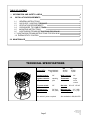
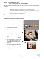
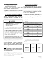
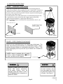
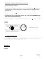
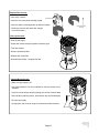
RENTAL
USERS MANUAL
GAS FIRED
INFRA RED
CONSTRUCTION HEATER
MODEL NUMBERS: SCH-90-N / SCH-90-L
SCH-90M-N / SCH-90M-L
CAUTION: Read all instructions before
use. Retain this manual for
further reference.
Page 1
SP-MCH9-BX-02B
SCH-90 Rental Manual
R.D: SEPT, 2004
RL:2
KH
NOTICE:
Schwank Inc., reserves the right to make
changes to equipment and specifications
without obligation or notification.
All codes are current at the time of printing.
This publication, or parts thereof, may not be reproduced in any form, without prior written
consent from Schwank Inc. Unauthorized
use or distribution of this publication
is strictly prohibited.
Schwank Inc.
5285 Bradco Boulevard
Mississauga, Ontario,
L4W 2A6
phone: (905) 712-4766
fax: (905) 712-8336
Schwank Inc.
PO Box 988
Waynesboro,
Georgia,USA 30830
Phone: (706) 554-6191
Technical Support: 1-877-446-3727
Fax: (706) 554 9390
e-mail: [email protected]
http://www.schwankheaters.com
Page 2
SP-MCH9-BX-02B
SCH-90 Rental Manual
R.D: SEPT, 2004
RL:2
KH
TABLE OF CONTENTS
— INFORMATION AND SAFETY LABELS
4
1.0
6
INSTALLATION REQUIREMENTS
6
6
6
6
7
8
8
9
1.1
GENERAL INSTRUCTIONS
1.2
GAS SUPPLY LINE/GAS PRESSURE
1.3
VENTILATION REQUIREMENTS
1.4
CLEARANCES TO COMBUSTIBLES
1.5
MOUNTING INSTRUCTIONS
1.6
LIGHTING/SHUTDOWN INSTRUCTIONS FOR SCH-90
1.7 LIGHTING/SHUTDOWN INSTRUCTIONS FOR SCH-90-M
1.8 THERMOSTATIC CONTROL
2.0 MAINTENANCE
9
TECHNICAL SPECIFICATIONS
Input (BTU) - Normal Altitude:
- High Altitude:
NG
90,000
81,000
LP
87,500
79,545
Height (inches):
36”
Width (inches):
24”
Ignition controls:
standing
pilot
Thermostat:
finger
touch
control
Tip-over switch:
35º
Gas inlet:
Clearances to:
Combustibles
24” (top)
48” (side)
Minimum gas:
6.3” (NG)
Pressure (W.C.) 11.3” (LP)
No electric power required.
Page 3
NG-1/2” LP-3/8”
Also available in 200,000 BTU
SP-MCH9-BX-02B
SCH-90 Rental Manual
R.D: SEPT, 2004
RL:2
KH
For Your Information and Safety …
Please read the following warning labels.
WARNING
WARNING
Failure to comply with the precautions and
instructions provided with this heater can result in
death, serious bodily injury and property loss,
damage from hazards of fire explosion, burn,
asphyxiation / carbon monoxide poisoning.
Only persons who can understand and follow the
instructions should use this heater. Service of this
heater should be performed by a qualified service
person only.
If you need assistance, or heater information such
as an instruction manual, labels, etc. contact your
local dealer.
FOR YOUR SAFETY
DO NOT store or use gasoline or other
flammable vapors and liquids in the vicinity of
this or any other appliance.
WHAT TO DO IF YOU SMELL GAS:
DO NOT try to light any appliance.
DO NOT touch any electrical equipment.
DO NOT use any telephone equipment in the
immediate area.
Immediately call your gas supplier or call the fire
department.
WARNING
Improper assembly, adjustment, alteration, service or maintenance can cause injury, property damage, or
death. For assistance or additional information, refer to this manual, or consult a qualified service agency, or
the gas supplier.
WARNING
Fire, burn, inhalation, and explosion hazard. Keep solid combustibles, such as building materials, paper or
cardboard, a safe distance away from the heater as recommended by the instructions. Never use the heater in
spaces that do or may contain volatile or airborne combustibles, or products such as gasoline, solvents, paint
thinner, dust particles or unknown chemicals.
Page 4
SP-MCH9-BX-02B
SCH-90 Rental Manual
R.D: SEPT, 2004
RL:2
KH
WARNING
DO NOT use heater in living or office areas.
Approved for heating buildings or structures
under construction, alteration or repair.
Use only in well ventilated areas.
Heater must be used exclusively for heating
purposes.
The distance between the heating surface top to
the nearest combustible must be at least 24
inches. The distance from the burner surface, in
a horizontal plane, to the nearest combustible
must be at least 48 inches.
The heater must not be directed towards any LP
gas container within 10 feet.
The fuel supply line must not be placed near the
burner heat zone.
WARNING
DO NOT store or use gasoline or other
flammable vapors or liquids in the vicinity of this
or any other appliance.
DO NOT use this heater if any part has been
under water. Call a professional gas appliance
service person to inspect the heater, and to
replace any part which has been under water.
Any changes to this heater or the heater’s
controls can be very dangerous.
Any part removed must be replaced prior to
operating the heater.
Failure to follow these warnings may result in
property damage, bodily injury or death.
The heater must be installed in such a way that it
is not directly exposed to water spray, rain and or
dripping water.
WARNING
NOT FOR HOME OR
RECREATIONAL VEHICLE USE
This heater is designed and approved for use as
a construction heater per Canadian Standard
2.14 and Ansi Z83.7 –2000.
CHECK WITH YOUR LOCAL FIRE SAFETY
AUTHORITY IF YOU HAVE ANY QUESTIONS
ABOUT APPLICATIONS.
Other standards
govern the use of fuel gases and heat producing
products in specific applications. Your local
authority can advise you about these.
Page 5
HEATER
MUST BE
LEVEL
BEFORE
OPERATING
SP-MCH9-BX-02B
SCH-90 Rental Manual
R.D: SEPT, 2004
RL:2
KH
NOTICE:
IF PILOT DOES NOT LIGHT
THE GAS SUPPLY HOSE MAY REQUIRE PURGING
If the heater pilot does not light within a minute, it may be due to air in the gas supply hose. Air must be purged
from the hose.
According to The Canadian B149.1-00 Natural Gas and Propane Installation Code:
5.23.7 When a piping or tube system is to be purged to the outdoors,
a. The purging line shall not terminate closer that 10 ft (3 m) from either a building or air intake;
b. The purging point shall be under the constant supervision of a competent person who shall control the purge by a
quarter turn lever handle valve within 5 ft (1.5 m) of the purge point. Such a valve shall have an attached operating
handle. No other valve shall be used to control or terminate the purge; and
c. Smoking shall not be permitted, and maximum precautions shall be taken to either remove or shut off any source
or potential source of ignition prior to commencing the purge.
and
5.23.9
When all piping and tubing systems and hose have been purged, the appliance piping shall be purged and the pilot burner
lighted.
A qualified person can purge the gas supply hose as follows:
1. Adhere to all requirements of the B149.1-00
Natural Gas and Propane Installation Code
as listed above.
2. Ensure that the purging of the hose takes
place at least 10 ft (3 m) from a building or
air intake.
3. Attach the hose to the gas supply
4. Open the lever handle valve at the end of the
hose that attaches to the heater
5. Use a ¼” nut driver to depress the valve ‘seat’
located inside the gas quick disconnect on the
end of the hose. (Do not use a screw driver
or other tool that can scratch/damage the
surface of the quick disconnect valve
‘seat’.)
¼” Nut Driver
6. Exert sufficient pressure to depress the valve
`seat’ to allow a flow of air from the hose.
When the smell of gas is apparent, release
the valve seat.
7. Close the lever handle valve on the gas hose.
Attach the hose to the HotTot construction
heater. Follow due diligence by performing
all required leak tests. Follow the directions
to light the pilot.
Page 6
SP-MCH9-BX-02B
SCH-90 Rental Manual
R.D: SEPT, 2004
RL:2
KH
1.0 INSTALLATION REQUIREMENTS
1.3 VENTILATION REQUIREMENTS
1.1 GENERAL INSTRUCTIONS
1. Examine contents for damage or missing parts
before proceeding with these instructions.
2. Installation of heaters must conform to all local codes.
3. Ensure that heater is level before operation.
1.2 GAS SUPPLY & PRESSURE INFORMATION
All piping and hose must be installed according to
local code, and must be of adequate size and
construction.
It has been determined that CO2 levels should not
exceed 5000 PPM (parts per million) and CO should
not exceed 35 PPM for an eight hour continuous exposure.
Combustion of gas fuel requires air. Each SCH-90
heater requires 90 sq.in. of opening for combustion
air. (ex.: 9” x 10” window opening)
To maintain the carbon dioxide content in the air at
or below the concentration mentioned above, the
number of air changes are listed below depending on
the size of the space being heated:
TABLE 1
WARNING
1. Minimum hose length –
Canada fifteen feet (15’) — USA ten feet (10’)
Maximum hose length—fifty feet (50’)
(3/4” inside diameter)
2. LP Gas Cylinder must be located a minimum ten
feet away from heater while heater is in operation.
3. After assembly and every time the heater is
attached to a new gas cylinder or gas meter, check
for leaks with a soap solution or leak tester on all
gas lines and connections. Failure to do so may
result in property damage, bodily injury or death.
DO NOT USE AN OPEN FLAME.
Required room air changes per hour
for each SCH-90 in operation.
Room Volume cu.ft.
No. of air changes /
5000
5
7,500
3
10,000
2.5
15,000
1.5
20,000
1.25
25,000
1
50,000
.5
If high pressure is used to check for leaks, do not
subject this heater’s controls to excessive pressure.
Natural gas models must have the supply line limited
to 14 inches (maximum) water column.
If the line pressure will go above 14 inches water
column at any time, a separate regulator must be
used. The minimum supply line pressure at the inlet to
the heater regulator must in no case be lower than 6.3
inches of water column.
Note: The regulator is an internal component of the
heater and maintains the heater’s manifold pressure;
natural gas is 5.5 inches water column, and LP gas is
10.5 inches water column.
1.4 CLEARANCES TO COMBUSTIBLES
TABLE 2
MODEL
SCH-90-N
SCH-90-L
SCH-90-M-N
SCH-90-M-L
SIDE
( From Radiant
Surface)
TOP
(From Radiant
Surface)
48”
48”
48”
48”
24”
24”
24”
24”
Heaters equipped for LP gas operations must have a
minimum supply line pressure 11.3 inches of water
column at the heater. Maximum line pressure is 1/2
PSI (14 inches water column).
Page 7
SP-MCH9-BX-02B
SCH-90 Rental Manual
R.D: SEPT, 2004
RL:2
KH
FIGURE
FIGURE 1:
1: SUSPENDED
SUSPENDEDFROM
FROMCEILING
CEILHeater may be suspended from ceiling using chain and mounting hardware
available from Schwank. When hanging from joists / beams the 24” clearance to
combustibles must be maintained, and measured from the bottom underside of
the joist or beam as per drawing, and NOT from the suspension anchoring point
of the chain. (See Table 2 page 6)
The Schwank HOT-TOT construction heater is CSA International approved to
be suspended as per these instructions and using the approved Schwank
supplied suspension hardware. (optional part #JH-0910-xx)
Note: Suspending heaters is not allowed in some jurisdictions, check your
local codes.
24” (MINIMUM)
1.5 MOUNTING INSTRUCTIONS
JOIST NO LESS THAN 2” X 6”
3/8” DIAMETER EYEHOOK DRIVE
THREADED PORTION FULLY
INTO JOIST THICKNESS.
2” (MINIMUM)
3/16” DRILL BIT
GAS LINE CONNECTION
FIGURE 2: FREE STANDING FLOOR MOUNT
A steel rod, non-combustible base is an integral part of this heater. The
heater may safely be placed directly on a combustible surface. Always
maintain minimum distance to combustibles as shown in Table 2. Gas
supply hose/piping must lay over the top of bottom rim of heater as
shown here.
NOTE: Heater is equipped with a tilt safety
feature. Heater will automatically shut down
when it is tilted over 900 degrees
WARNING
GAS SUPPLY LINE
CAUTION
Surface of heater will be hot to the
touch. Take proper precautions.
If the heater location must be
changed, allow the heater to cool a
full 15 minutes before attempting to
handle the heater.
On floor mounted units,
the Gas supply line must
lay above the bottom rim
of heater. See Figure 2.
Page 8
SP-MCH9-BX-02B
SCH-90 Rental Manual
R.D: SEPT, 2004
RL:2
KH
1.6 LIGHTING / SHUTDOWN INSTRUCTIONS For SCH 90 N/L
1. Pre-purge gas line prior to lighting.
2. Place knob in the OFF position, rotate knob 1 notch, or “click” counter-clockwise.
Depress and
hold the control knob. Light pilot through porthole. Release knob after sixty seconds. Pilot burns,
main burner is off.
3. Turn knob counter-clockwise
to ignite main burner. Adjust knob to desired heat setting.
4. If burner does not light, turn knob completely clockwise .
knob. Wait five minutes and repeat step two.
Leave in off position without pressing
5. For complete shutdown of burner and pilot, turn knob completely clockwise,
then depress knob.
FIGURE 3
PILOT / VEILLEUSE
PLUS CHAUD
/ WARMER
OFF / ARRÊT
Thermostatic Control Knob
note: this is an Instructional Sticker Only
1.7 THERMOSTATIC CONTROL
Multifunctional gas control with snap acting thermostat, thermo-electric flame-failure safety device, and
a manual ON/OFF function. Thermostat range is 50ºF - 100ºF.
MAINTENANCE
See page 9.
Page 9
SP-MCH9-BX-02B
SCH-90 Rental Manual
R.D: SEPT, 2004
RL:2
KH
1.8 LIGHTING / SHUTDOWN INSTRUCTIONS - For SCH 90-M- N/L
1. Pre-purge gas line prior to lighting.
2. Turn the knob counterclockwise to PILOT position, push the knob down and hold in position. The
pilot valve opens and allows gas to flow to the pilot burner.
3. While holding the knob down, light the pilot burner, continue to hold knob down until a strong flame
is present, continue holding for an additional 60 seconds.
4. Release the knob. The shaft moves upward and engages the safety valve level that opens the
safety valve.
5. Turn the knob counterclockwise to the ON position. On a call-for-heat the main valve opens and
the main burner ignites.
6. To shut off the system, turn the knob clockwise to the OFF position. This action closes the main
gas and safety valves. However the power unit must drop out before the lighting sequence can
begin again. The valve drops out within three minutes.
Thermostat range is 50o F
to 100o F. Turn Thermostat
clockwise to increase the
room temperature.
Turn counter clockwise all
the way to shut off, call for
heat pilot is on for standby.
2.0 MAINTENANCE
This heater should be cleaned at least once annually with a dry cloth. This heater should be inspected
before each use and at least once annually by a qualified service person.
The gas hose assembly shall be visually inspected prior to each use of the heater. If damage is evident
it must be replaced prior to the heater being placed into operation. For replacement part information,
see pages 12 & 14.
LP model heaters should use a standard LP gas cylinder. Cylinder must be located a minimum of 10
feet away from heater while heater is in operation. The cylinder must be provided with a system for vapor withdrawal. The gas must be turned off at the LP gas supply cylinder when the heater is not in use.
The connection of the gas cylinder should be made with the #510 connector which tightens by turning
the threads to the left. To disconnect the fitting make sure the gas is turned off, and loosen threads by
turning them to the right. When heater is to be stored indoors the connection between the LP gas cylinder and the heater must be disconnected.
Keep appliance area free and clear from combustible materials, gasoline and other flammable vapors
and liquids. Ensure that the flow of combustion and ventilation air is free from all obstructions.
Page 10
SP-MCH9-BX-02B
SCH-90 Rental Manual
R.D: SEPT, 2004
RL:2
KH
Replace filter at least:
- once every 2 weeks
FILTER RETAINER
- minimum once a day when sanding drywall
- each time when connecting heater at different location
FILTER RETAINER
& FILTER
* Clean burner screen with each filter change;
( see next window )
FILTER
Filter replacement:
- Shut off gas supply
- Grasp filter retainer and pull together at retainer grips
- Free filter retainer
- Remove and discard filter
- Replace with a new filter
- Reinstall filter retainer, complete with filter
Clearing Burner Screen:
- Make sure gas supply is off
- Use compressed air If air is not available on the site, aerosol can is
available:
- Insert air nozzle through the pilot lighting hole at side of mantle base
- Direct at flame retaining screen, and blow out any accumulated dust
- Re-open gas supply
- Re-light pilot, and continue using the construction heater as before.
COMPRESSED AIR
Page 11
SP-MCH9-BX-02B
SCH-90 Rental Manual
R.D: SEPT, 2004
RL:2
KH