1
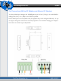
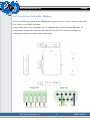
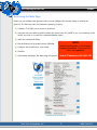
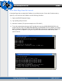
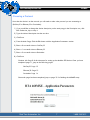
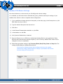
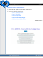
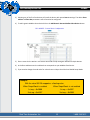
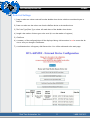
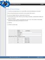
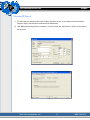
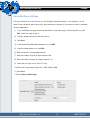
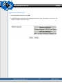
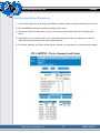
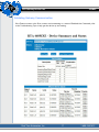
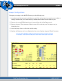
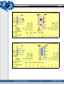
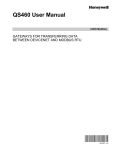
460MXE Gateway
User Guide
Trademarks
CompactLogix, ControlLogix, & PLC-5 are registered trademarks of Rockwell Automation, Inc.
EtherNet/IP is a trademark of the Open DeviceNet Vendors Association (ODVA).
MicroLogix, RSLogix 500, and SLC are trademarks of Rockwell Automation, Inc.
Microsoft, Windows, and Internet Explorer are registered trademarks of Microsoft Corporation.
All other trademarks and registered trademarks are the property of their holders.
Limited Warranty
Real Time Automation, Inc. warrants that this product is free from defects and functions properly.
EXCEPT AS SPECIFICALLY SET FORTH ABOVE, REAL TIME AUTOMATION, INC. DISCLAIMS ALL OTHER WARRANTIES, BOTH EXPRESSED AND IMPLIED, INCLUDING BUT
NOT LIMITED TO IMPLIED WARRANTIES OF MERCHANTABILITY OR FITNESS FOR A
PARTICULAR APPLICATION. THIS LIMITED WARRANTY GIVES YOU SPECIFIC LEGAL
RIGHTS. YOU MAY ALSO HAVE OTHER RIGHTS, WHICH VARY FROM STATE TO STATE.
The examples and diagrams in this manual are included solely for illustrative purposes. Because of the
many variables and requirements associated with any particular application, Real Time Automation,
Inc. cannot assume responsibility or liability for actual use based on the examples and diagrams. Except as specifically set forth above, Real Time Automation and its distributors and dealers will in no
event be liable for any damages whatsoever, either direct or indirect, including but not limited to loss
of business profits, income, or use of data. Some states do not allow exclusion or limitation of incidental or consequential damages; therefore, the limitations set forth in this agreement may not apply to
you.
No patent liability is assumed by Real Time Automation with respect to use of information, circuits,
equipment, or software described in this manual.
Government End-Users
If this software is acquired by or on behalf of a unit or agency of the United States Government, this
provision applies: The software (a) was developed at private expense, is existing computer software,
and was not developed with government funds; (b) is a trade secret of Real Time Automation, Inc. for
all purposes of the Freedom of Information Act; (c) is “restricted computer software” submitted with
restricted rights in accordance with subparagraphs (a) through (d) of the Commercial “Computer Software-Restricted Rights” clause at 52.227-19 and its successors; (d) in all respects is proprietary data
belonging solely to Real Time Automation, Inc.; (e) is unpublished and all rights are reserved under
copyright laws of the United States. For units of the Department of Defense (DoD), this software is
licensed only with “Restricted Rights”: as that term is defined in the DoD Supplement of the Federal
Acquisition Regulation 52.227-7013 (c) (1) (ii), rights in Technical Data and Computer Software and
its successors, and: Use, duplication, or disclosures is subject to restrictions as set forth in subdivision
(c) (1) (ii) of the Rights in Technical Data and Computer Software clause at 52.227-7013. If this software was acquired under GSA schedule, the U.S. Government has agreed to refrain from changing or
removing any insignia or lettering from the Software or documentation that is provided or from producing copies of the manual or media. Real Time Automation, Inc., 150 S. Sunnyslope Rd. Suite 130,
Brookfield, WI 53005.
© 2008 Real Time Automation, Inc. All rights reserved.
460 Gateway Device Line
460MXE
Overview
The 460MXE gateway device seamlessly connects power and energy data between one or more Eaton
Power Meters and a BACnet/IP Client or Ethernet/IP Client or DeviceNet Master.
By following this guide, you will be able to configure the 460MXE gateway for basic operation. You will
set the device’s network settings and parameters to the proper configuration for initial operation and
physically place the device in the network.
For further customization and advanced use contact support at Real Time Automation..
Real Time Automation, Inc.
1
1-800-249-1612
460 Gateway Device Line
460MXE
Required Tools and Data
You will need the following tools:
♦
The 460MXE Gateway
♦
The provided CD-ROM
♦
A Working PC (Windows based)
♦
The Supplied Ethernet crossover cable
♦
A 7-30 VDC power source (T-strip)
You will also need to verify the following Modbus Slave Settings:
♦
Data Timeout
♦
Baud Rate
♦
Parity
♦
Data Bits
♦
Stop Bits
Real Time Automation, Inc.
2
1-800-249-1612
460 Gateway Device Line
460MXE
Port Connections (BACnet/IP / Modbus and Ethernet/IP / Modbus)
The factory default port settings on the 460MXE gateway are for Port 0 (T-strip) to be set for RS485 including power (Pin 5). Port 1 (DB9) is set to RS232 by default.
If these default port are not compatible with your equipment they can be configured differently. For specific jumper settings refer to the end of this manual, appendix A. For assistance changing port configurations contact our customer support department.
Real Time Automation, Inc.
3
1-800-249-1612
460 Gateway Device Line
460MXE
Port Connections (DeviceNet / Modbus)
The factory default port settings on the 460MXE gateway are for Port 0 (T-strip) to be set for CAN while
Port 1 (DB9) is set to RS485 by default.
If these default port are not compatible with your equipment they can be configured differently. For
specific jumper settings refer to the end of this manual, appendix A. For assistance changing port
configurations contact our customer support department.
Real Time Automation, Inc.
4
1-800-249-1612
460 Gateway Device Line
460MXE
Accessing the Main Page
Before you can configure the gateway itself you must configure the network settings to connect the
gateway. The following steps will connect the gateway properly.
1) Connect a 7-30 VDC power source to the device.
2) Using the crossover cable (supplied) connect the device to the PC. (NOTE: If you are connecting to the
device via a hub or a switch use a standard Ethernet cable.)
3) Insert the provided CD-ROM.
NOTE
4) Run the IPSetup.exe program from the CD-ROM.
5) Configure the IP address for your subnet.
6) Click Set.
7) Click Launch Webpage. The Main page will appear.
Real Time Automation, Inc.
Browser configuration is only Internet
Explorer compatible. The use of FireFox is not supported.
Default IP address is 192.168.0.100
5
1-800-249-1612
460 Gateway Device Line
460MXE
Error: Main Page Does Not Launch
If the Main Page does not launch the IP address is most likely incorrect. Correct the IP address and try
again. If you do not know the IP address use the following procedure:
1) Open an MS-DOS Command Prompt.
2) Type ipconfig and press enter.
3) Note the IP address. (The previous example was 192.168.0.1)
4) To test the communication between the PC and the unit, type ping (###.###.###.###) in the
prompt and press enter. The (###.###.###.###) is a placeholder for the IP address you used in
step 5 of network configuration which was192.168.0.100. If the device is connected to the network
the ping will show a response. If you get no response check the crossover cable and any other
network devices.
Real Time Automation, Inc.
6
1-800-249-1612
460 Gateway Device Line
460MXE
Choosing a Protocol
Now that the device is on the network you will need to select what protocol you are connecting to
(BACnet/IP or Ethernet/IP or DeviceNet).
1) If you would like to change the device description, on the main page, in the Description row, click
Edit. Otherwise, skip to step 4.
2) Type the desired description into the text box.
3) Click Save.
4) From the Main Page, Click the Edit button with the Application Parameters section
5) Enter a 0 to transfer data to BACnet/IP
6) Enter a 1 to transfer data to Ethernet/IP
7) Enter a 2 to transfer data to DeviceNet
8) Click Save
Continue with Page 8 of this document for setting up the Modbus RTU device. Once you have
completed page 11, jump to the following pages:
BACnet/IP: Page 12
Ethernet/IP: Page 13
DeviceNet: Page 14
Once each page has been completed, jump to page 15 for finishing the 460MXE setup.
Real Time Automation, Inc.
7
1-800-249-1612
460 Gateway Device Line
460MXE
Modbus RTU Master Settings
Now that the device is on the network you will configure the device settings.
As a reminder you will need to know the baud rate, parity, data bits and stop bit settings of your
Modbus slave device in order to complete device configuration.
1) If you would like to change the device description, on the main page, in the Description row, click
Edit. Otherwise, skip to step 4.
2) Type the desired description into the text box.
3) Click Save.
4) In the Selected Communication Modules row, click Edit.
5) In the Modbus row click Edit.
6) Verify that the Enabled box is checked.
7) Response Timeout is set to 500 ms by default and should suffice for most applications. Delay
Between Polls (time between scan line requests) is set to 50 ms by default. These values can be
changed to suit your requirements.
8) Select the appropriate settings in the Connector, Mode, Baud, Parity, Data and Stop fields. The
settings should match your Modbus Slave device.
If your data is not flowing correctly after installing the device on the network,
check that the settings selected match the settings of your Modbus Slave device.
Incorrect settings will skew operation.
Real Time Automation, Inc.
8
1-800-249-1612
460 Gateway Device Line
460MXE
Configuring External Master Modules
1) From the Main page click Edit in the Client Module Configuration row.
2) There are four options for external devices:
♦
Eaton IQ 250/260 Power Meter
♦
Eaton IQ 130, 140, 150
♦
Eaton Power Xpert 2000
♦
Eaton Power Xpert 4000, 6000, 8000
♦
Add Generic Remote Modbus RTU Slave
(Continued on page 10)
Real Time Automation, Inc.
9
1-800-249-1612
460 Gateway Device Line
460MXE
3) Selecting any of the first four devices will install the device with preset Data In settings. The device Slave
address and Data Out parameters will still need to be configured.
4) To add a generic Modbus slave device click on the Add Generic Remote Modbus Slave Device button.
5) Enter a name for the device in the Device Label field to help distinguish between multiple devices.
6) In the Slave address enter the address that corresponds to your Modbus Slave Device.
7) If you need to change the read order for values that are 4 bytes check the box labeled Swap Words.
Example:
With the value 302.25 mapped as a floating value.
When Swap Words is enabled
When Swap Words is not enabled
1st reg. = 0x2000
1st reg. = 0x4397
2nd reg. = 0x4397
2nd reg. = 0x2000
Real Time Automation, Inc.
10
1-800-249-1612
460 Gateway Device Line
460MXE
Scan List Settings
1) Data in values are values received from the Modbus slave device which are considered inputs to
BACnet.
2) Data out values are the values sent from the BACnet device to the Modbus slave.
3) The Point Type/Data Type values will match those of the Modbus slave device.
4) Length is the number of data types to be read. (It is not the number of registers)
5) Click Save.
6) A summary of the configured data will be displayed along with instructions in red to restart the device to save your changes. Click Restart.
7) A confirmation box will appear, click Restart Now. You will be redirected to the main page.
Real Time Automation, Inc.
11
1-800-249-1612
460 Gateway Device Line
460MXE
BACnet IP Server Settings
1) Scroll down to the BACnet Server row and click Edit. Verify that the Enabled box is checked.
2) Enter the Device Instance that corresponds with your Modbus Slave device/s.
3) In the Device Name field enter a unique name for the device.
4) The Description and Locations fields are optional. Filling in the fields is recommended to identify the
device on a network.
5) Beneath # of Objects to Expose, values should all be kept as zero. These values are dynamically
determined by the runtime of the Modbus slave scan list.
6) Click Save.
7) Click Return to Main Page.
Real Time Automation, Inc.
12
1-800-249-1612
460 Gateway Device Line
460MXE
Ethernet/IP Server
1) For the Data Out column do the same as Step 8 except use the correct Output Instance Number,
Length in bytes, and Required Pack Interval in milliseconds.
2) Click Save when configuration is complete. You must restart the 460 device in order for the data to
be updated.
Real Time Automation, Inc.
13
1-800-249-1612
460 Gateway Device Line
460MXE
DeviceNet Slave Settings
Now that the device is on the network, you will configure the device settings. As a reminder, you will
need to know the mode, baud rate, parity, data and stop bit settings of your device in order to complete
device configuration.
1) If you would like to change the device description, on the main page, in the Description row, click
Edit. Otherwise, skip to step 4.
2) Type the desired description into the text box.
3) Click Save.
4) In the Selected Communication Modules row, click Edit.
5) In the DeviceNet Master row, click Edit.
6) Enter the device’s corresponding Mac ID.
7) Enter the number of Bytes for Input Instance 100
8) Enter the number of Bytes for Output Instance 112
9) Select the port type to use. (Port 0: T-strip)
10) Select the corresponding baud rate. (125K, 250K, 500K)
11) Click Save.
12) Click Return to Main Page.
Real Time Automation, Inc.
14
1-800-249-1612
460 Gateway Device Line
460MXE
Application Parameters
1) Next Application Parameters click Edit.
2) 460MXE Mapping will display the connection between the tags / file names in your PLC to the
BACnet/IP Object within your Client.
Real Time Automation, Inc.
15
1-800-249-1612
460 Gateway Device Line
460MXE
Verifying Application Parameters
1) On the Main Page click on the Status and Summary button located on the left hand side of the screen.
2) The 460MXE Device Summary and Status page will be shown.
3) The device drop down menu allows you to switch between the different devices and display their
status.
4) Under Show you can choose to show only values that are greater than zero. Summary can be left
unchecked as that feature has not been implemented yet.
5) The Device Summary and Status section displays whether or not the device is connected and enabled.
Real Time Automation, Inc.
16
1-800-249-1612
460 Gateway Device Line
460MXE
Validating Gateway Communication
If the Timeout counter or the Error counter are incrementing or a status of Enabled Not Connected, refer
to the Troubleshooting Tops to help get the device up and running.
Real Time Automation, Inc.
17
1-800-249-1612
460 Gateway Device Line
460MXE
Configuring Multiple Devices
If you are configuring multiple devices the same way, you can repeat the configuration by saving your
work into a file. To do so, follow these steps.
1) From the Main Page, click the Utilities button.
2) Click Save Configuration to File.
3) Click Save.
4) Browse to the location you want to save the file.
5) Click OK.
6) Remove the first device.
7) Repeat the network configuration section to connect the next device.
8) Once you launch the webpage, click the Utilities button.
9) Click Browse… and navigate to the file you previously saved.
10) Click Open.
11) Click Restore from File.
Real Time Automation, Inc.
18
1-800-249-1612
460 Gateway Device Line
460MXE
Completing the Installation
Now that the 460MXE gateway is configured properly you must place the device in the network. The following instructions will tell you how to take the device from the configuration area to the shop floor or
other operating environment.
1) Disconnect the crossover cable and power supply from the device.
2) Move the device to its intended location.
3) For Bacnet/IP or Ethernet/IP, follow steps 4-6. For DeviceNet, skip to step 7.
4) Attach the Ethernet cable from the BACnet/IP Client / Ethernet/IP Client to the network port on the
460MXE Gateway.
5) Attach the Modbus RTU serial cable to Port 0 (T-strip) or Port 1 (DB-9) of the 460MXE Gateway.
6) Connect the 7-30 VDC power source to the device via the T-strip.
7) Attach the Modbus connection from the Modbus RTU Slave/s to the port Port 1 (DB9) of the
460MMDS.
8) Attach the T-Strip connection from the DeviceNet Master device to Port 0 (T-Strip) of the 460MMDS
Gateway.
9) Connect the 7-30 VDC power source to the device via the T-strip.
Real Time Automation, Inc.
19
1-800-249-1612
460 Gateway Device Line
460MXE
Jumper Configurations
To change port settings on the 460 EDX Gateway use the following steps:
1) No cables should be connected to the Gateway unit. If this unit has been in use and you are making a
change, disconnect the power cable and any communications cables from the Gateway unit.
2) Remove the two small Phillips-head screws from each long side of the Gateway unit.
3) Remove the green T-Strip connector. Slide the cover off towards the ports. The jumpers are just
behind the ports.
4) Move the jumper shunts to reflect the desired settings.
5) Replace the Gateway unit’s cover. Replace the four screws. Replace the green T-Strip5 connector.
Only one RS232, RS485, or CAN port setting can be active at a time for each unit.
For example, a unit cannot have two ports set for RS232 or two ports set for CAN.
NC=No connection
Port 0 (T-Strip) RS485 & PWR 1
2
3
4
5
Pin Setting
GND
TX-
TX+
NC
PWR
Port 1 (DB-9) RS232
1
2
3
4
5
6
7
8
9
Pin Setting
NC
RX
TX
NC
GND
NC
NC
NC
NC
Real Time Automation, Inc.
A
1-800-249-1612
460 Gateway Device Line
460MXE
NC= No connection
Port 0 (T-Strip) CAN
1
2
3
4
5
Pin Setting
GND
CANL SHIELD
CANH PWR
Port 1 (DB-9) RS485
1
2
3
4
5
6
7
8
9
Pin Setting
NC
TX-
NC
NC
GND
NC
TX+
NC
NC
NC= No connection
Port 0 (T-Strip) CAN
1
2
3
Pin Setting
GND
CANL
SHIELD CANH PWR
Port 1 (DB-9) RS232
1
2
3
4
5
6
7
8
9
Pin Setting
NC
RX
TX
NC
GND
NC
NC
NC
NC
Real Time Automation, Inc.
4
5
B
1-800-249-1612
Real Time Automation, Inc.
150 South Sunny Slope Road Suite 130
Brookfield WI 53005
Toll free 1-800-249-1612
Local (262) 439-4999
www.rtaautomation.com
[email protected]