1
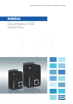
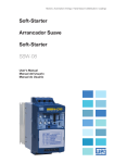
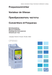
Motors | Automation | Energy | Transmission & Distribution | Coatings Frequency Inverter MW500 User's Manual User’s Manual Series: MW500 Language: English Document Nº: 10002218015 / 01 Publishing Date: 02/2015 Summary of Reviews The information below describes the reviews made in this manual. Review Description Chapter 00 01 First edition General review and inclusion of frame A - NOTE! The inverters MW500 have the default parameters set as described below: 50 Hz for models with internal filter (check the smart code E.g.: MW500B06P5T4). ATTENTION! Check the frequency of the power supply. In case the power supply frequency is different from the default frequency (check P0403), it is necessary to set: P0204 = 5 for 60 Hz. P0204 = 6 for 50 Hz. It is only necessary to set these parameters once. Refer to the programming manual of the MW500 for further details about the setting of parameter P0204. Index 1 SAFETY INSTRUCTIONS......................................................................1 1.1 SAFETY WARNINGS IN THIS MANUAL.....................................................1 1.2 SAFETY WARNINGS IN THE PRODUCT...................................................1 1.3 PRELIMINARY RECOMMENDATIONS......................................................2 2 GENERAL INFORMATION....................................................................3 2.1 ABOUT THE MANUAL ................................................................................3 2.2 ABOUT THE MW500...................................................................................3 2.3 NOMENCLATURE.......................................................................................5 2.4 IDENTIFICATION LABELS..........................................................................6 2.5 RECEIVING AND STORAGE.......................................................................7 3 INSTALLATION AND CONNECTION....................................................8 3.1 MECHANICAL INSTALLATION...................................................................8 3.1.1 Environmental Conditions................................................................8 3.1.2 Positioning and Mounting................................................................8 3.2 ELECTRICAL INSTALLATION....................................................................9 3.2.1 Identification of the Power Terminals and Grounding Points.....9 3.2.2 Power and Grounding Wiring, Circuit Breakers and Fuses.........9 3.2.3 Power Connections.........................................................................10 3.2.3.1 Input Connections........................................................................10 3.2.3.2 IT Networks................................................................................... 11 3.2.3.3 Dynamic Braking.......................................................................... 11 3.2.3.4 Output Connections.................................................................... 13 3.2.4 Grounding Connections................................................................. 14 3.2.5 Control Board.................................................................................. 14 3.2.6 Control Connections....................................................................... 14 3.2.7 Cable Separation Distance............................................................ 17 3.3 INSTALLATIONS ACCORDING TO EUROPEAN DIRECTIVE OF ELECTROMAGNETIC COMPATIBILITY ................................................. 17 3.3.1 Conformal Installation .................................................................. 17 3.3.2 Emission and Immunity Levels......................................................18 4 KEYPAD (HMIR) AND BASIC PROGRAMMING ...............................19 4.1 USE OF THE HMIR TO OPERATE THE DRIVE........................................ 19 4.2 INDICATIONS ON THE HMIR DISPLAY...................................................20 4.3 OPERATING MODES OF THE HMIR .......................................................21 Index 5 POWERING UP AND START-UP........................................................25 5.1 PREPARATION AND POWERING UP.......................................................25 5.2 CONSIDERATIONS FOR INTEGRATED MOUNTING IN VENTILATED MOTORS ................................................................................26 5.3 START-UP ..................................................................................................27 5.3.1 Start-up (using Superdrive and default circuit configuration)..27 5.3.2 STARTUP Menu (Using Remote Keypad (HMIR)) .......................28 5.3.2.1 V/f Control Type (P0202 = 0) .......................................................28 5.3.2.2 V V W Control Type (P0202 = 5)...................................................29 5.3.3 Menu BASIC – Basic Application..................................................31 6 TROUBLESHOOTING AND MAINTENANCE.....................................32 6.1 FAULT AND ALARMS................................................................................32 6.2 SOLUTIONS FOR THE MOST FREQUENT PROBLEMS........................32 6.3 DATA TO CONTACT THE TECHNICAL ASSISTANCE............................33 6.4 PREVENTIVE MAINTENANCE.................................................................33 6.5 CLEANING INSTRUCTIONS ....................................................................34 7 OPTIONAL KITS AND ACCESSORIES ............................................35 7.1 OPTIONAL KITS ........................................................................................35 7.1.1 RFI Filter............................................................................................35 7.1.2 Disconnecting Switch ...................................................................35 7.2 ACCESSORIES...........................................................................................35 8 TECHNICAL SPECIFICATIONS .........................................................37 8.1 POWER DATA ............................................................................................37 8.2 ELECTRONICS/GENERAL DATA.............................................................37 8.2.1 Codes and Standards.....................................................................38 APPENDIX A – PARTS............................................................................40 APPENDIX B – TECHNICAL SPECIFICATIONS...................................44 APPENDIX C – MOUNTING INSTRUCTIONS.......................................48 Safety Instructions 1 SAFETY INSTRUCTIONS This manual contains the information necessary for the correct use of the MW500 drive. It was developed to be operated by people with proper technical training or qualification to handle this kind of equipment. Those people must follow the safety instructions defined by the local standards. The noncompliance with the safety instructions may cause risk of death and/or damages to the equipment. 1.1 SAFETY WARNINGS IN THIS MANUAL DANGER! The procedures recommended in this warning aim at protecting the user against death, serious injuries and considerable material damages. ATTENTION! The procedures recommended in this warning aim at preventing material damages. NOTE! The information mentioned in this warning is important for the proper understanding and good operation of the product. 1.2 SAFETY WARNINGS IN THE PRODUCT High voltages present. Components sensitive to electrostatic discharges. Do not touch them. The connection to the protection grounding is required (PE). Connection of the shield to the grounding. High temperature warning. - English - MW500 | 1 Safety Instructions 1.3 PRELIMINARY RECOMMENDATIONS DANGER! Always disconnect the general power supply before changing any electric component associated to the drive. Many components may remain loaded with high voltages and/or moving (fans), even after the AC power supply is disconnected or turned off. Wait for at least ten minutes in order to guarantee the full discharge of the capacitors. Always connect the grounding point of the drive to the protection grounding. NOTES! The MW500 drive may interfere in other electronic equipment. Observe the recommendations of chapter 3 - Installation and Connection in order to minimize these effects. Read the entire manual before installing or operating this drive. Do not execute any applied withstand voltage test on the drive! If necessary, contact WEG. ATTENTION! The electronic boards have components sensitive to electrostatic discharges. Do not touch the components or connectors directly. If necessary, first touch the grounding point of the drive, which must be connected to the protection ground or use a proper grounding strap. ATTENTION! Do not touch the enclouser of the drive directly. The drive may be very hot during and after the operation. 2 | MW500 - English - General Information 2 GENERAL INFORMATION 2.1 ABOUT THE MANUAL This manual contains information for the proper installation and operation of the drive, as well as start-up procedures, main technical features and how to identify the most usual problems of the different models of the MW500 series of drives. ATTENTION! The operation of this equipment requires detailed installation and operation instructions provided in the user’s manual, programming manual and communication manuals. The user’s manual and the quick reference of the parameters are supplied at the purchase of the drive, while the guides are supplied with their respective accessories. Other manuals are only supplied in CD-ROM, which comes with the drive, or can be downloaded in WEG’s website - www.weg.net. This CD must be always kept with this equipment. A printed copy of the files available in the CD can be requested at your local WEG dealer. NOTE! It is not the intention of this manual to present all the possibilities for the application of the MW500, as well as WEG cannot take any liability for the use of the MW500 which is not based on this manual. 2.2 ABOUT THE MW500 The MW500 is a high-performance, decentralized motordrive with IP66 degree of protection which allows speed and torque control of three-phase induction motors. This product features vector (VVW) and scalar (V/f) control - both programmable according to your application. In the vector control mode (VVW), the operation is optimized for the motor in use, providing a better performance in terms of speed regulation. The scalar mode (V/f) is recommended for simpler applications, such as the activation of most pumps and fans. The V/f mode is used when more than one motor is activated by a drive simultaneously (multimotor applications). The MW500 can be mounted on the motor or on the wall, depending on the application requirements. The MW500 drive also provides PLC functions (Programmable Logic Controller) by means of the SoftPLC (integrated) feature. For further details regarding the programming of those functions on the MW500, refer to the SoftPLC user's manual of the MW500. - English - MW500 | 3 General Information The main components of the MW500 are shown in the block diagram of figure 2.1. = Bus connection DC = Connection for brake resistor BR DC+ DC- Precharge R/L1 U/T1 V/T2 RFI filter T/L3 W/T3 Rectifier Disconnecting switch PE Braking IGBT S/L2 DC link capacitors bank Power supply Motor Inverter with IGBT´s Current feedback Dedicate knob for reference POWER CONTROL Supplies for electronics and interfaces between power and control MW500 Keypad (remote) (**) CPU 32 bits "RISC" EEPROM (memory) CONTROL XC10 PLUG-IN MODULE Power supply 10 V PC RS-485 Software WLP SUPERDRIVE (*) MODBUS Interface (RS232, RS485 or USB) Power supply 24 V Analog output (AO1) (*) User’s Plug-in Card Digital output DO1 (RL1) Digital Input (DI1 to DI4) (*) Digital output DO2 (TR) (*) Analog Input (AI1) (*) Memory Card (MCard) Accessory (*) The number of analog/digital inputs/outputs, as well as other resources, may vary according to the plug-in module used. Table 7.1 provides a list of the available plug-ins. For further information, refer to the guide supplied with the accessory or the CD-ROM. (**) Not provided with the product. Figure 2.1: Block diagram of the MW500 Part of the figures and tables are available in the appendixes, which are divided into Appendix A for parts, Appendix B for technical specifications and Appendix C for mounting instructions. 4 | MW500 - English - General Information 2.3 NOMENCLATURE Table 2.1: Nomenclature of the MW500 drives Identification of the Model Product Conducted Degree of Disconnecting Hardware and Brake Emission Connection Box Rated N° of Rated Protection Switch Version Series Frame Level Current Phases Voltage Ex.: MW500 B 06P5 T 4 DB 66 C2 DS A56 DB = with dynamic braking Available options --- A56 = motor connection box size 56x56mm A70 = motor connection box size 70x70mm See table 2.2. Special Software Version -Blank = standard Sx = special software Blank = standard plug-in module H00 = without plug-in MW500 DS = with disconnecting switch Blank = without disconnecting switch 66 = IP66/Nema4X (degree of protection) Blank = It does not meet the standards leves for conducted emission. C2 = with internal RFI filter Table 2.2: Available options for each field of the nomenclature according to the rated current and voltage of the drive Rated Output Frame Current 04P3 = 4.3 A A 06P0 = 6.0 A 02P6 = 2.6 A 04P3 = 4.3 A B 06P5 = 6.5 A 10P0 =10.0 A N° of Phases Rated Voltage S = single-phase power supply 2 = 200...240 V T = three-phase power supply 4 = 380…480 V S = single-phase power supply 2 = 200...240 V Available Options for the Remaining Identification Codes of the Drives Brake Degree of Protection DB 66 - English - Conducted Disconnecting Connection Emission Level Switch Box Blank or C2 Blank or DS A56 or A70 MW500 | 5 General Information 2.4 IDENTIFICATION LABELS There are two identification labels: one complete nameplate, located on the side of the drive and a simplified label inside the drive shown in figure 2.2. The simplified label over the plug-in module allows the identification of the most important characteristics of the drive, even in drives mounted side-by-side. For further details about the position of the labels, see figure A.2 and A.3 of Appendix A. MW500 model Serial number WEG part number Manufacturing date Rated output data (voltage, current and frequency) Rated input data (voltage, current and frequency) (a) Side label of the MW500 (Inside the drive) MW500 model WEG part number Serial number Manufacturing date (b) Simplified internal label (over the plug-in module) Figure 2.2 (a) and (b): Description of the identification labels on the MW500 6 | MW500 - English - General Information 2.5 RECEIVING AND STORAGE The MW500 is supplied packed in a cardboard box. On this package, there is an identification label which is the same as the one attached to the side of the drive. Check if: The Any identification of the MW500 matches the model purchased. damages occurred during transportation. Report any damage immediately to the carrier. If the MW500 will not be installed soon, store it in a clean and dry location (temperature between -25 °C and 60 °C (-13 °F and 140 °F)), with a cover to protect it against dust accumulation and in consequence maintain the dissipation capacity of the drive. ATTENTION! When the drive is stored for a long period, it is necessary to perform the capacitor reforming. Refer to the procedure recommended in section 6.4 - Preventive Maintenance of this manual. - English - MW500 | 7 Installation and Connection 3 INSTALLATION AND CONNECTION 3.1 MECHANICAL INSTALLATION 3.1.1 Environmental Conditions Avoid: Direct exposure to sunlight. Inflammable or corrosive liquids or Dust, metallic particles or oil mist. gases. Environmental conditions permitted for the operation of the drive: Temperature surrounding the inverter: from 0 ºC (32 °F) to the rated temperature specified as follows: 40 ºC (104 °F) – Nema4x/IP66 (mounted on the wall). 50 ºC (122 °F) – Nema4x/IP66 (mounted integrated on the motor). For temperatures surrounding the inverter higher than the specifications above, it is necessary to apply a derating on the current of 2 % for each Celsius degree ( or 1.11 % each °F), limited to an increase of 10 ºC (50 °F). Air relative humidity: 5 % to 90 % non-condensing. Maximum altitude: up to 1000 m (3,300 ft) - standard conditions (no derating required). From 1000 m to 4000 m (3,300 ft to 13,200 ft) current derating of 1 % each 100 m (or 0.3 % each 100 ft) above 1000 m (3,300 ft) altitude. From 2000 m to 4000 m (6,600 ft to 13,200 ft) maximum voltage reduction (480 V for 380…480 V models) of 1.1 % for each 100 m (330 ft) above 2000 m (6,600 ft) altitude. Pollution degree: 2 (according to EN50178 and UL508C), with non-conductive pollution. Condensation must not originate conduction through the accumulated residues. 3.1.2 Positioning and Mounting The external dimensions, the net weight (mass) of the drive and the suggested torque values are presented in figure B.1 of Appendix B. Integrate the motor For assembling of the drive onto the motor follow the step by step guide in figure C.1 of Appendix C. Wall mounted For assembling of the drive in the wall follow the step by step guide in figure C.2 of Appendix C. ATTENTION! Provide independent conduits for the physical separation of signal, control, and power cables (refer to section 3.2 - Electrical Installation). 8 | MW500 - English - Installation and Connection 3.2 ELECTRICAL INSTALLATION DANGER! The following information is merely a guide for proper installation. Comply with the applicable local regulations for electrical installations. Make sure the power supply is disconnected before starting the installation. The MW500 must not be used as an emergency stop device. Provide other devices for that purpose. 3.2.1 Identification of the Power Terminals and Grounding Points The location of the power, grounding and control connections are shown in figure A.2. Description of the power terminals: Terminal X1 (L1/L, L2/N and L3 (R, S, T, )): AC power supply. Terminal X2 (U/T1, V/T2, W/T3, ): connection for the motor. Terminal X3 (DC-, BR, DC+, ): DC bus and brake connection. DC- is the negative pole of the voltage of the DC bus, BR is the connection of the brake resistor and DC+ is the positive pole of the voltage of the DC bus. 3.2.2 Power and Grounding Wiring, Circuit Breakers and Fuses ATTENTION! Use proper cable lugs for the power and grounding connection cables. Refer to table B.1 for recommended wiring, circuit breakers and fuses. Keep sensitive equipment and wiring at a minimum distance of 0.25 m from the drive and from the cables connecting the drive to the motor. It is not recommended the use of mini circuit breakers (MDU), because of the actuation level of the magnet. NOTE! The wire gauges listed in table B.1 are approximate values. Installation conditions and the maximum permitted voltage drop must be considered for the proper wiring sizing. - English - MW500 | 9 Installation and Connection 3.2.3 Power Connections Shield U/T1 V/T2 W/T3 U/T1 V/T2 W/T3 WEG industrial motor R/L1 S/L2 T/L3 Input power supply R/L1 S/L2 T/L3 Fuses Figure 3.1: Power and grounding connection 3.2.3.1 Input Connections ATTENTION! The power supply that feeds the drive must have a grounded neutral. In case of IT networks, follow the instructions described in item 3.2.3.2 - IT Networks. NOTE! The input power supply voltage must be compatible with the drive rated voltage. Capacitors for power factor correction are not needed at the drive input (L1/L, L2/N, L3 or R, S, T) and must not be installed at the output (U/T1, V/T2, W/T3). 10 | MW500 - English - Installation and Connection Power supply capacity The MW500 is suitable for use in a circuit capable of delivering not more than 30.000 Arms symmetrically (200 V - 480 V). In case the MW500 is installed in power supplies with current capacity over 30.000 Arms, it is necessary to use proper protection circuits for those power supplies, such as fuses or circuit breakers. 3.2.3.2 IT Networks ATTENTION! When drives with internal RFI filter is used in IT networks (neutral conductor not grounded or grounded through a high ohmic value resistor), remove grounding screw XE1, since those kinds of network cause damage to the filter capacitors of the drive. 3.2.3.3 Dynamic Braking Refer to table B.1 for the following specifications of the dynamic braking: maximum current, recommended resistance, effective current (*) and cable gauge. Input Power supply Contactor R R S S T T BR Control power supply DC+ Thermal relay Thermostat Brake resistor Figure 3.2: Installation of brake resistor (*) The effective braking current can be calculated as follows: - English - MW500 | 11 Installation and Connection Ieffective = Imax . √ tbr (min) 5 Where: tbr corresponds to the sum of the braking actuation times during the most severe cycle of five minutes. The power of the brake resistor must be calculated considering the deceleration time, the inertia of the load and of the resistive torque. Procedure to use the dynamic braking: the brake resistor between the power terminals DC+ and BR (X3). Use a twisted cable for the connection. Separate these cables from the signal and control wiring. Dimension the cables according to the application, observing the maximum and effective currents. If the brake resistor is mounted within the cabinet of the drive, consider its energy when dimensioning the ventilation of the cabinet. Connect DANGER! The internal braking circuit and the resistor may be damaged if the latter is not properly dimensioned and/or if the voltage of the input power supply exceeds the maximum permitted value. In order to avoid the destruction of the resistor or risk of fire, the only guaranteed method is the inclusion of a thermal relay in series with the resistor and/or a thermostat in contact with its housing, connected so as to disconnect the input power supply of the drive in case of overload, as shown in figure 3.2. Set P0151 to the maximum value when using dynamic braking. voltage level on the DC bus for activation of the dynamic braking is defined by parameter P0153 (level of the dynamic braking). Refer to the MW500 programming manual. The 12 | MW500 - English - Installation and Connection 3.2.3.4 Output Connections ATTENTION! The drive has an electronic motor overload protection that must be adjusted according to the driven motor. When several motors are connected to the same drive, install individual overload relays for each motor. The motor overload protection available in the MW500 is in accordance with the UL508C standard. Note the following information: 1. Trip current equal to 1.2 times the motor rated current (P0401). 2. When parameters P0156, P0157 and P0158 (Overload current at 100 %, 50 % and 5 % of the rated speed, respectively) are manually set, the maximum value to meet condition 1 is 1.1 x P0401. ATTENTION! If a disconnect switch or a contactor is installed at the power supply between the drive and the motor, never operate it with the motor spinning or with voltage at the drive output. The characteristics of the cable used to connect the motor to the drive, as well as its interconnection and routing, are extremely important to avoid electromagnetic interference in other equipment and not to affect the life cycle of windings and bearings of the controlled motors. Keep motor cables away from other cables (signal cables, sensor cables, control cables, etc.), according to item 3.2.7 - Cable Separation Distance. Connect a fourth cable between the motor ground and the drive ground. When using shielded cables to install the motor: Follow the safety recommendations of IEC60034-25. Use the low impedance connection for high frequencies to connect the cable shield to the grounding. Use parts supplied with the drive. - English - MW500 | 13 Installation and Connection Figure 3.3: Details of the connection of the motor cable 3.2.4 Grounding Connections DANGER! The drive must be connected to a protection grounding (PE). Use grounding wiring with a gauge at least equal to that indicated in table B.1. The maximum tightening torque of the grounding connections is of 1.7 N.m (15 lbf.in). Connect the grounding points of the drive to a specific grounding rod, or specific grounding point or to the general grounding point (resistance ≤ 10 Ω). Do not share the grounding wiring with other equipment that operate with high currents (e.g. high power motors, soldering machines, etc.). 3.2.5 Control Board Plug-in modules are connected to control board. S10 DIP-switch are available in control board, for more information refer to section 4.3 - Operating Modes of the HMIR. 3.2.6 Control Connections The control connections (analog input/output, digital input/output and interface RS485) must be performed according to the specification of the connector of the plug-in module connected to the MW500. Refer to the guide of the plug-in module in print or in the CD of the product. The typical functions and connections for the CFW500-IOS standard plug-in module are shown in figure 3.4. For further details about the specifications of the connector signals, refer to chapter 8 - Technical Specifications. 14 | MW500 - English - DI4 DI3 Upper Terminal DO1-RL-NF DO1-RL-C DO1-RL-NA Connector +24 V DI2 DI1 Installation and Connection DI1 Digital Input 1 3 DI2 Digital Input 2 (*) 5 DI3 Digital Input 3 7 DI4 Digital Input 4 9 +24 V Power Supply +24 Vdc 11 DO1-RL-NA 13 DO1-RL-C Lower Terminal GND RS485 - B DO2-TR +10 V AI1 GND rpm ≥5 kΩ >300 Ω RS485 - A 15 DO1-RL-NF AO1 Description (**) 1 Digital Output 1 (Relay NO Contact 1) Digital Output 1 (Relay Common Point 1) Digital Output 1 (Relay NC Contact 1) 2 AO1 4 GND Analog Output 1 Reference 0 V 6 AI1 Analog Input 1 8 +10 V Reference +10 Vdc for Potentiometer 10 DO2-TR Digital Output 2 (Transistor) 12 RS485 - A RS485 (Terminal A) 14 RS485 - B RS485 (Terminal B) 16 GND Reference 0 V Digital input 2 (DI2) can also be used as input in frequency (FI). For further details refer to the programming manual of the MW500. (**) For further information, refer to the detailed specification in section 8.2 - Electronics/General Data. (*) Figure 3.4: Signals of the connector of the CFW500-IOS plug-in module The location of the plug-in module and DIP-switches to select the type of analog input and output signal and the termination of the RS485 network is shown in figure A.1. The MW500 drives are supplied with the digital inputs configured as active low (NPN), analog input and output configured for signal in voltage 0…10 V and with the termination resistor of the RS485 OFF. NOTE! To use the analog inputs and/or outputs with signal in current, you must set switch S1 and related parameters as per table 3.1. For further information, refer to the MW500 programming manual. To modify the digital inputs from active low to active high, check the use of parameter P0271 in the MW500 programming manual. - English - MW500 | 15 Installation and Connection Table 3.1: Configuration of the switches to select the type of analog input and output signal on the CFW500-IOS Input/ Output AI1 AO1 Signal Setting of Switch S1 Signal Range Parameter Setting Voltage S1.1 = OFF 0...10 V P0233 = 0 (direct reference) or 2 (inverse reference) Current S1.1 = ON 0...20 mA P0233 = 0 (direct reference) or 2 (inverse reference) 4...20 mA P0233 = 1 (direct reference) or 3 (inverse reference) Voltage S1.2 = ON 0...10 V P0253 = 0 (direct reference) or 3 (inverse reference) 0...20 mA P0253 = 1 (direct reference) or 4 (inverse reference) 4...20 mA P0253 = 2 (direct reference) or 5 (inverse reference) Current S1.2 = OFF NOTE! Configuration to connect the RS485: S1.3 = ON and S1.4 = ON: terminal RS485 ON. S1.3 = OFF and S1.4 = OFF: terminal RS485 OFF. Any other combination of the switches is not allowed. For the correct connection of the control, use: 1) Gauge of the cables: 0.5 mm² (20 AWG) to 1.5 mm² (14 AWG). 2) Maximum torque: 0.5 N.m (4.50 lbf.in). 3)Wiring of the plug-in module connector with shielded cables separated from the other wiring (power, command in 110 V / 220 Vac, etc.), according to item 3.2.7 Cable Separation Distance. If those cables must cross other cables, it must be done perpendicularly, keeping the minimum separation distance of 5 cm (1.97 in) at the crossing point. Connect the shield according to the figure below: Insulate with Tape Inverter Side Do Not Ground Figure 3.5: Connection of the shield 4) Relays, contactors, solenoids or coils of electromechanical brakes installed close to the drives may occasionally generate interference in the control circuitry. To eliminate this effect, RC suppressors (with AC power supply) or freewheel diodes (with DC power supply) must be connected in parallel to the coils of these devices. 5) When using the external HMIR (refer to section 7.2 - Accessories), the cable that connects to the drive must be separated from the other cables in the installation, keeping a minimum distance of 10 cm (3.94 in). 6) When using analog reference (AI1) and the frequency oscillates (problem of electromagnetic interference), interconnect the GND of the connector of the plug-in module to the drive grounding connection. 16 | MW500 - English - Installation and Connection 3.2.7 Cable Separation Distance Provide separation between the control and power cables and between the control cables (relay output cables and other control cables) as per table 3.2. Table 3.2: Cable separation distance Drive Rated Output Current ≤ 24 A Cable Length (s) Minimum Separation Distance ≤ 100 m (330 ft) > 100 m (330 ft) ≥ 10 cm (3.94 in) ≥ 25 cm (9.84 in) 3.3 INSTALLATIONS ACCORDING TO EUROPEAN DIRECTIVE OF ELECTROMAGNETIC COMPATIBILITY Drives with option C2 or C3 (MW500...C2...) feature internal RFI filter in order to reduce the electromagnetic interference. Those drives, when properly installed, meet the requirements of the directive of electromagnetic compatibility. The MW500 drive series was developed for professional applications only. Therefore, the emission limits of harmonic currents by the standards EN 61000-3-2 and EN 61000-3-2/A 14 are not applicable. 3.3.1 Conformal Installation 1) Drive with optional internal RFI filter MW500...C2... (with grounding switch of the capacitors of the internal RFI filter in the position ON). Check the installation of the grounding screw in figure A.2. 2) Shielded output cables (motor cables) with the shield connected at both ends, motor and drives, by means of low impedance for high frequency connection. Maximum motor cable length and conducted and radiated emission levels according to table B.3. If a lower conducted emission level and/or a longer motor cable is desired, then an external RFI filter must be used at the drive input. For more information (RFI filter commercial reference, motor cable length and emission levels) refer to the table B.3. 3) Shielded control cables, keeping the separations distance from other cables according to table 3.2. 4) Grounding of the drive according to instructions of item 3.2.4 - Grounding Connections. 5) Grounded power supply. - English - MW500 | 17 Installation and Connection 3.3.2 Emission and Immunity Levels Table 3.3: Emission and immunity levels EMC Phenomenon Basic Standard Level Emission: Mains Terminal Disturbance Voltage Frequency Range: 150 kHz to 30 MHz) IEC/EN61800-3 It depends on the drive model and on the length of the motor cable. Refer to table B.3. Electromagnetic Radiation Disturbance Frequency Range: 30 MHz to 1000 MHz) Immunity: Fast Transient-Burst IEC 61000-4-4 2 kV / 5 kHz (coupling capacitor) input cables. 1 kV / 5 kHz control cables and remote HMIR cables. 2 kV / 5 kHz (coupling capacitor) motor cables. Conducted Radio-Frequency Common Mode IEC 61000-4-6 0.15 to 80 MHz; 10 V; 80 % AM (1 kHz). Motor, control and HMIR cables. Surges IEC 61000-4-5 1.2/50 μs, 8/20 μs. 1 kV line-to-line coupling. 2 kV line-to-ground coupling. Radio-Frequency Electromagnetic Field IEC 61000-4-3 80 to 1000 MHz 10 V/m 80 % AM (1 kHz) Definition of Standard IEC/EM 61800-3: “Adjustable Speed Electrical Power Drives Systems” Environments: First Environment: Environments that include domestic installations, as well as establishments directly connected without intermediate transformer to a low-voltage power supply network which supplies buildings used for domestic purposes. Second Environment: includes all establishments other than those directly connected to a low-voltage power supply network that supplies buildings used for domestic purposes. Categories: Category C1: drives with a rated voltage below 1000 V and intended for use in the First Environment. Category C2: drives with a rated voltage below 1000 V intended for use in the First Environment, not provided with a plug connector or movable installations. They must be installed and commissioned by a professional. NOTE! A professional is a person or organization familiar with the installation and/or commissioning of drives, including their EMC aspects. Category C3: drives with a rated voltage below 1000 V and intended for use in the Second Environment only (not designed for use in the First Environment). 18 | MW500 - English - Keypad (HMIR) and Basic Programming 4 KEYPAD (HMIR) AND BASIC PROGRAMMING 4.1 USE OF THE HMIR TO OPERATE THE DRIVE Through the HMIR, it is possible to command the drive, view and set all of its parameters. The HMIR presents two operating modes: monitoring and setting. The functions of the keys and fields of the display active on the HMIR vary according to the operating mode. The setting mode is composed of three levels. - When in the monitoring mode: press this key to enter the setting mode. - When in the setting mode, level 1: press this key to select the desired parameter group – it shows the parameter group selected. - When in the setting mode, level 2: press this key to show the parameter – it shows the content of the parameter in order to change the content. - When in the setting mode, level 3: press this key to save the new content of the parameter – it returns to level 2 of the setting mode. - When in the setting mode, level 1: press this key to return to the monitoring mode. - When in the setting mode, level 2: press this key to return to level 1 of the setting mode. - When in the setting mode, level 3: press this key to cancel the new value (new value is not saved) and return to level 2 of the setting mode. - When in the monitoring mode: press this key to increase the speed. - When in the setting mode, level 1: press this key to go to the previous group. - When in the setting mode, level 2: press this key to go to the next parameter. - When in the setting mode, level 3: press this key to increase the content of the parameter. - When in the monitoring mode: press this key to decrease the speed. - When in the setting mode, level 1: press this key to go to the next group. - When in the setting mode, level 2: press this key to go to the previous parameter. - When in the setting mode, level 3: press this key to decrease the content of the parameter. Press this key to accelerate the motor within the time determined by the acceleration ramp. Active when: P0224 = 0 in LOC or P0227 = 0 in REM Press this key to define the motor rotation direction. Active when: P0223 = 2 or 3 in LOC and/or P0226 = 2 or 3 in REM Press this key to decelerate the motor within the time determined by the deceleration ramp. Active when: P0224 = 0 in LOC or P0227 = 0 in REM Press this key to commute between LOCAL and REMOTE mode. Active when: P0220 = 2 or 3 Press this key to accelerate the motor up to the speed set in P0122 within the time determined by the acceleration ramp. The motor speed is kept while the key is pressed. When the key is released, the motor decelerates within the time determined by the deceleration ramp, until it stops. This function is active when all the conditions below are met: 1. Turn/Stop = Stop; 2. Enable general = Active.; 3. P0225 = 1 in LOC and/or P0228 = 1 in REM. Figure 4.1: HMIR keys - English - MW500 | 19 Keypad (HMIR) and Basic Programming 4.2 INDICATIONS ON THE HMIR DISPLAY Inverter status Secondary indication Menu (to select the parameter groups) – only one parameter group is shown at a time. Measurement unit (it refers to the value of the main indication) Bar graph Main display Figure 4.2: Display fields Parameter groups available in the field Menu: PARAM: all parameters. READ: reading parameters only. MODIF: parameters modified in relation to the default only. BASIC: parameters for basic application. MOTOR: parameters related to the control of the motor. I/O: parameters related to digital and analog inputs and outputs. NET: parameters related to the communication networks. HMIR: parameters to configure the HMIR. SPLC: parameters related to the SoftPLC. STARTUP: parameters for oriented Start-up. Status of the drive: LOC: command source or local references. REM: command source or remote references. : direction of motor rotation by means of arrows. CONF: configuration error. SUB: undervoltage. RUN: execution. 20 | MW500 - English - Keypad (HMIR) and Basic Programming 4.3 OPERATING MODES OF THE HMIR The HMIR must be configured via hardware on S10 DIP-switch before the operation. The S10 is shown in figure A.2 of Appendix A. For recognizing the HMIR the drive can be adjusted as shown in table 4.1. Table 4.1: S10 DIP-switches configuration Switches Status S1 ON S2 OFF S3 OFF S4 OFF The monitoring mode allows the user to view up to three variables on the main display, secondary display and bar graph. Such fields of the display are defined in figure 4.2. The setting mode is composed of three levels: Level 1 allows the user to select the Menu items in order to browse the parameters. Level 2 allows browsing the parameters of the group selected by level 1. Level 3 allows the modification of the parameter selected in Level 2. At the end of this level, the modified value is saved or not if the key ENTER or ESC is pressed, respectively. - English - MW500 | 21 Keypad (HMIR) and Basic Programming Figure 4.3 illustrates the basic browsing of the operating modes of the HMIR. Monitoring Mode It is the initial status of the HMIR after the powering up and of the initialization screen, with default values. The field Menu is not active in this mode. The main display, secondary display and bar graph indicate the values of three parameters predefined by P0205, P0206 and P0207. From the monitoring mode, when you press the key ENTER/MENU, you commute to the setting mode. Setting Mode Level 1: This is the first level of the setting mode. It is possible to choose the parameter group using the keys and . The main display, secondary display, bar graph and measurement units are not shown in this level. Press the key ENTER/MENU to go to level 2 of the setting mode – parameter selection. Press the key BACK/ESC to return to the monitoring mode. Monitoring BACK ESC Setting Level 1 BACK ESC Level 2: The number of the parameter is shown on the main display and its content on the secondary display. Use the keys and to find the desired parameter. Press the key ENTER/MENU to go to level 3 of the setting mode – modification of the parameter content. Press the key BACK/ESC to return to level 1 of the setting mode. ENTER MENU Setting Level 2 BACK ESC Level 3: The content of the parameter is shown on the main display and the number of the parameter is shown on the secondary display. Use the keys and to configure the new value for the selected parameter. Press the key ENTER/MENU to confirm the modification (save the new value) or BACK/ ESC to cancel the modification (not save the new value). In both cases, the HMIR returns to level 2 of the setting mode. ENTER MENU Setting Level 3 Figure 4.3: Operating modes of the HMIR 22 | MW500 ENTER MENU - English - Keypad (HMIR) and Basic Programming NOTE! When the drive is in the fault state, the main display indicates the number of the fault in the format Fxxxx. The browsing is allowed after the activation of the key ESC, and the indication Fxxxx goes to the secondary display until the fault is reset. NOTE! When the drive is in the alarm state, the main display indicates the number of the Alarm in the format Axxxx. The browsing is allowed after the activation of any key, and the indication Axxxx goes to the secondary display until the situation causing the alarm is solved. NOTE! A list of parameters is presented in the quick reference of the parameters. For further information about each parameter, refer to the programming manual of the MW500. - English - MW500 | 23 Keypad (HMIR) and Basic Programming 24 | MW500 - English - Powering up and Start-up 5 POWERING UP AND START-UP 5.1 PREPARATION AND POWERING UP The drive must be installed according the chapter 3 - Installation and Connection. DANGER! Always disconnect the general power supply before making any connections. 1) Check if the power, grounding and control connections are correct and firm. 2) Remove all materials left from the inside of the drive. 3) Check if the motor connections and motor current and voltage match the drive. 4) Mechanically uncouple the motor from the load. If the motor cannot be uncoupled, be sure that its turning in any direction (clockwise or counterclockwise) will not cause damages to the machine or risk of accidents. 5) Close the covers of the drive. 6) Measure the voltage of the input power supply and check if it is within the permitted range, as presented in chapter 8 - Technical Specifications. 7) Power up the input: close the disconnecting switch. 8) Check the success of the powering up: The display of the HMIR indicates: Figure 5.1: Display of the HMIR at power-up The drive executes some routines related to data upload or download (parameter configurations and/or SoftPLC). The indication of those routines is presented in the bar graph. After those routines, if there are no problems, the display will show the monitoring mode. - English - MW500 | 25 Powering up and Start-up 5.2 CONSIDERATIONS FOR INTEGRATED MOUNTING IN VENTILATED MOTORS In order to keep the temperature rise of WEG motors within acceptable levels, the following loadability limits must be attended (observe the motor line with constant flux condition in figure 5.2). This condition can be adjusted in P0406 where the overload motor protection was pre adjusted for attend the derating. 1.05 1.00 [TR] - Torque reduction (p.u.) 0.95 0.90 for temperature rise of thermal class F (105 K) 0.85 0.80 0.75 0.70 for temperature rise of thermal class B (80 K) 0.65 0.60 0.55 0.50 0.45 0.40 0.00.1 0.2 0.3 0.4 0.5 0.60.7 0.80.9 1.0 1.1 1.2 1.3 1.4 1.5 1.6 1.7 1.81.9 2.0 2.1 [f/fn] - Frequency (p.u.) Figure 5.2: Torque derating 26 | MW500 - English - Powering up and Start-up 5.3 START-UP 5.3.1 Start-up (using Superdrive and default circuit configuration) When there is no possible to use the HMIR to start-up the drive, it is possible to use the Superdrive configuration software for parameters setting and default circuit configuration for start-up, as shown in figure 5.3. GND DO1-NC DO1-C DO1-NO +24 V Shield DI4 DI3 DI2 S2 S3 S4 DI1 S1 13579111315 GND B(+) A(-) DO2 +10 V AI1 GND AO1 246810 121416 Figure 5.3: Default circuit configuration For default configuration the commands of the drive are the following: Table 5.1: Default functions configurations Function DIx Run/Stop DI1 (S1) FWD/REW DI2 (S2) Reset DI3 (S3) LOC/REM DI4 (S4) Speed reference is set via knob reference. - English - MW500 | 27 Powering up and Start-up 5.3.2 STARTUP Menu (Using Remote Keypad (HMIR)) The start-up is explained in a very simple way, using the programming features with the existing parameter groups in the menus STARTUP and BASIC. After the hardware pre-configuration, the drive will operate with a different control type. 5.3.2.1 V/f Control Type (P0202 = 0) Seq Indication on the Display / Action Seq Indication on the Display / Action 6 1 Monitoring mode. Press the key ENTER/MENU to enter 1st level of programming mode. 2 If necessary, modify the content of “P0401 – Motor Rated Current”. Press the key for the next parameter. 7 The PARAM group is selected, press the keys or until selecting the STARTUP group. 3 If necessary, modify the content of “P0402 – Motor Rated Speed”. Press the key for the next parameter. 8 When the STARTUP group is selected press the key ENTER/MENU. 4 If necessary, modify the content of “P0403 – Motor Rated Frequency”. Press the key for the next parameter. 9 If necessary, press ENTER/MENU to modify the content of “P0202 – Control Type” for P0202 = 0 (V/f). To end the Start-up routine, press the Key BACK/ESC. To return to the monitoring mode, press the key BACK/ESC again. 5 When the desired value is reached, press ENTER/MENU to save the modification. Press the key for the next parameter. Figure 5.4: Sequence of the Start-up group for V/f control 28 | MW500 - English - Powering up and Start-up 5.3.2.2 V V W Control Type (P0202 = 5) Seq Indication on the Display / Action Seq Indication on the Display / Action 6 1 Monitoring mode. Press the key ENTER/MENU to enter the 1st level of the programming mode. 2 Press the key to proceed with the Start-up of the V V W. If necessary, modify the content of “P0399 – Motor Rated Performance”, or press the key for the next parameter. If necessary, modify the content of “P0400 – Motor Rated Voltage”, or press the key for the next parameter. If necessary, modify the content of “P0401 – Motor Rated Current”, or press the key for the next parameter. If necessary, modify the content of “P0402 – Motor Rated Rotation”, or press the key for the next parameter. 7 The PARAM group is selected, press the Keys or until selecting the STARTUP group. 3 8 When the STARTUP group is selected press the key ENTER/MENU. 4 9 Press ENTER/MENU and with the keys and set the value 5, which activates the control mode V V W. 5 10 Press ENTER /MENU to save the modification of P0202. Figure 5.5: Sequence of the Start-up group for V V W control - English - MW500 | 29 Powering up and Start-up Seq Indication on the Display / Action 11 Seq Indication on the Display / Action 16 If necessary, modify the content of “P0403 – Motor Rated Frequency”, or press the Key for the next parameter. 12 If necessary, modify the content of “P0404 – Motor Rated Power”, or press the key for the next parameter. 17 13 The result of Self-Adjustment is the value in ohms of the motor stator resistance shown in P0409. This is the last parameter of the SelfAdjustment of the V V W control mode. Press the key to return to initial parameter P0202. 18 If necessary, modify the content of “P0407 – Motor Rated Power Factor”, or press the key for the next parameter. 14 15 At the end of the Self-Adjustment, the value of P0408 automatically returns to “0”, as well as the Status of “RUN” and “CONF” are cleared. Press the key for the next parameter. To exit the STARTUP menu, just press BACK/ESC. Through the keys and , select the desired menu or press the key BACK/ESC again to return directly to the monitoring mode of the HMIR. 19 At this point, the HMIR shows the option to do the self-adjustment. Whenever possible, perform the self-adjustment. Thus, to activate the selfadjustment, change the value of P0408 to “1”. uring the Self-Adjustment the HMIR will D simultaneously indicate the status of “RUN” and “CONF”. And the bar graph indicates the progress of the operation. And the bar graph indicates the progress of the operation. The Self-Adjustment can be interrupted at any time by means of the key . Figure 5.5 (cont.): Sequence of the Start-up group for V V W control 30 | MW500 - English - Powering up and Start-up 5.3.3 Menu BASIC – Basic Application Seq Indication on the Display / Action Seq Indication on the Display / Action 6 1 Monitoring mode. Press the key ENTER/MENU to enter the 1st level of the programming mode. 2 If necessary, modify the content of “P0133 – Minimum Speed”. Press the key for the next parameter. 7 The PARAM group is selected, press the keys or until selecting the BASIC group. 3 If necessary, modify the content of “P0134 – Maximum Speed”. Press the key for the next parameter. 8 When the BASIC group is selected press the key ENTER/MENU. 4 If necessary, modify the content of “P0135 – Maximum Output Current”. Press the key for the next parameter. 9 Basic Application routine is star ted. If necessary, modify the content of “P0100 – Acceleration Time”. Press the key for the next parameter. To end the Start-up routine, press the key BACK/ESC. To return to the monitoring mode, press the key BACK/ESC again. 5 If necessary, modify the content of “P0101 – Deceleration Time”. Press the key for the next parameter. Figure 5.6: Sequence of the Basic Application group - English - MW500 | 31 Troubleshooting and Maintenance 6 TROUBLESHOOTING AND MAINTENANCE 6.1 FAULT AND ALARMS NOTE! Refer to the quick reference and to the programming manual of the MW500 for further information about each fault or alarm. 6.2 SOLUTIONS FOR THE MOST FREQUENT PROBLEMS Table 6.1: Solutions for the most frequent problems Problem Motor will not start Motor speed oscillates Too high or too low motor speed Display off 32 | MW500 Point to be verified Corrective Action Incorrect wiring 1. Check all the power and command connections. Analog reference (if used) 1. Check if the external signal is properly connected. 2. Check the status of the control potentiometer (if used). Wrong settings 1. Check if the parameter values are correct for the application. Fault 1. Check if the drive is disabled due to a fault condition. Motor stall 1. Decrease the motor overload. 2. Increase P0136, P0137 (V/f). Loose connections 1. Stop the drive, turn off the power supply and tighten all the connections. 2. Check all the internal connections of the drive. Defective speed reference potentiometer Oscillation of the external analog reference 1. Replace the potentiometer. Incorrect settings (reference limits) 1. Check whether the content of P0133 (minimum speed) and P0134 (maximum speed) are properly set for the used motor and application. Control signal of the analog reference (if used) Motor nameplate 1. Check the level of the reference control signal. 2. Check the setting (gain and offset) of parameters P0232 to P0240. 1. Check whether the motor used matches the application. HMIR connections Power supply voltage 1. Check the connections of the drive external HMIR. 1. Rated values must be within the limits specified below: 380-480 V power supply: - Min: 323 V - Max: 528 V. Main supply fuse open 1. Replace the fuses. 1. Identify the cause of the oscillation. If the cause is electrical noise, use shielded cables or separate them from the power or command wiring. 2. Interconnect the GND of the analog reference to the grounding connection of the drive. - English - Troubleshooting and Maintenance 6.3 DATA TO CONTACT THE TECHNICAL ASSISTANCE For information or service request, it is important to have at hand the following data: Drive model. Serial number and manufacturing date of the product found in the identification label (refer to section 2.4 - Identification Labels). Software version installed (see P0023 and P0024). Information about the application and programming executed. 6.4 PREVENTIVE MAINTENANCE DANGER! Always disconnect the general power supply before changing any electric component associated to the drive. High voltages can be present even after the disconnection of the power supply. Wait for at least ten minutes for the full discharge of the power capacitors. Always connect the frame of the equipment to the protection grounding (PE) at the proper point for that. ATTENTION! The electronic boards have components sensitive to electrostatic discharges. Do not touch components or connectors directly. If necessary, first touch the grounded metallic frame or use a proper grounding strap. Do not execute any applied potential test on the drive. If necessary, contact WEG. When installed in proper environment and operating conditions, the drives require little service. Table 6.2 lists the main procedures and intervals for routine maintenance. Table 6.3 suggests inspections on the product every 6 months after start-up. Table 6.2: Preventive maintenance Maintenance Internal fan replacement Electrolytic capacitors Interval Instructions After 40,000 hours of operation. Replacement. If the drive is stocked (not in use): “Reforming” Every year from the manufacturing date printed on the drive identification label (refer to section 2.5 - Receiving and Storage). Apply power to the drive with voltage between 380 and 480 Vac, single-phase or three-phase, 50 or 60 Hz, for at least one hour. Then, disconnect the power supply and wait for at least 24 hours before using the drive (reapply power). Drive being used: replace Every 10 years. Contact WEG technical support to obtain replacement procedure. - English - MW500 | 33 Troubleshooting and Maintenance Table 6.3: Periodic inspection every 6 months Component Terminals, connectors Printed circuit boards Power module/ Power connections DC bus capacitors (DC link) Power resistors Heatsink Abnormality Loose screws Loose connectors Accumulation of dust, oil, humidity, etc. Odor Accumulation of dust, oil, humidity, etc. Loose connection screws Discoloration / odor / electrolyte leakage Safety valve expanded or broken Frame expansion Discoloration Odor Accumulation of dust Dirt Corrective Action Tighten Cleaning Replacement Cleaning Tightening Replacement Replacement Cleaning 6.5 CLEANING INSTRUCTIONS When it is necessary to clean the drive, follow the instructions below: External cleaning: The drive is fully washable according the IEC-60529 normative. 34 | MW500 - English - Optional Kits and Accessories 7 OPTIONAL KITS AND ACCESSORIES 7.1 OPTIONAL KITS The optional kits are hardware resources added to the drive in the manufacturing process. 7.1.1 RFI Filter Built-in RFI filter option is available to reduce the conducted disturbance from the drive to the main power supply in the high frequency band (>150 kHz). It is necessary to meet the maximum levels of conducted and radiated emissions of electromagnetic compatibility standards, such as EN 61800-3 and EN 55011. For further details, refer to section 3.3 - Installations According to European Directive of Electromagnetic Compatibility. ATTENTION! When drives with internal RFI filter is used in IT networks (neutral conductor not grounded or grounded through a high ohmic value resistor), remove grounding screw XE1, since those kinds of network cause damage to the filter capacitors of the drive. 7.1.2 Disconnecting Switch An integrated disconnecting switch is available as an option. 7.2 ACCESSORIES The accessories are hardware resources that can be added to the application. The accessories are incorporated to the drives in an easy and quick way by using the “Plug and Play” concept. When an accessory is connected to the drive, the control circuitry identifies the model and informs the code of the accessory connected in parameter P0027. The accessory must be installed or modified with the drive deenergized. They may be ordered separately and are sent in their own package containing the components and manuals with detailed instructions for their installation, operation and setting. - English - MW500 | 35 Optional Kits and Accessories Table 7.1: Accessory models WEG Item Name Description Control Accessories (refer to table 7.2 for additional information) 11518579 CFW500-IOS Standard Plug-in module. 11769748 CFW500-IOD Digital Input and Output Plug-in Module (I/O). 11769749 CFW500-IOAD 11635754 CFW500-IOR 11631564 CFW500-CUSB USB Communication Plug-in Module. 11593087 CFW500-CCAN CAN Communication Plug-in Module. 11950925 CFW500-CRS485 12443605 CFW500-CPDP2 Digital and Analog Input and Output Plug-in Module (I/O). Digital Relay Output Communication Plug-in Module. RS485 Communication Plug-in Module. PROFIBUS Communication Plug-in Module. Flash Memory Module 11636485 CFW500-MMF Flash Memory Module. Adaptation Accessories 13100469 MW500-KCFA-CL56 Wall adapter plate for frame A and connection box 56x56mm. 13100470 MW500-KCFA-CL70 Wall adapter plate for frame A and connection box 70x70mm. 12362338 MW500-KCFB-CL56 Wall adapter plate for frame B and connection box 56x56mm. 13100468 MW500-KCFB-CL70 Wall adapter plate for frame B and connection box 70x70mm. 12778122 MW500-KAIM-A56 Connection box 56x56mm for frame A. 12778123 MW500-KAIM-B56 Connection box 56x56mm for frame B. 12778124 MW500-KAIM-B70 Connection box 70x70mm for frame B. 12597760 MW500-KIP66OD Outdoor plugs kit. HMIR Accessories 11833992 CFW500-HMIR Remote Keypad (HMIR) - IP20 degree of protection. 12378837 MW500-CCHMIR0,5M Coiled communication wire for connection of IP20 keypad via XC10 connector. 12330016 CFW500-CCHIR01M (*) 1 m cable kit. 12330459 CFW500-CCHIR02M (*) 2 m cable kit. 12330460 CFW500-CCHIR03M (*) 3 m cable kit. 12330461 CFW500-CCHIR05M (*) 5 m cable kit. 12330462 CFW500-CCHIR75M (*) 7.5 m cable kit. 12330463 CFW500-CCHIR10M (*) 10 m cable kit. (*) For internal connection of IP20 keypad. Table 7.2: I/O configurations of plug-in modules Functions Module DI AI AO DOR DOT USB CAN RS232 RS485 PROFIBUS 10 V 24 V Source Source CFW500-IOS 4 1 1 1 1 - - - 1 - 1 1 CFW500-IOD 8 1 1 1 4 - - - 1 - 1 1 CFW500-IOAD 6 3 2 1 3 - - - 1 - 1 1 CFW500-IOR 4 1 1 4 1 - - - 1 - 1 1 CFW500-CUSB 4 1 1 1 1 1 - - 1 - 1 1 CFW500-CCAN 2 1 1 1 1 - 1 - 1 - 1 1 CFW500-CRS485 4 1 1 1 1 - - - 2 - 1 1 CFW500-CPDP2 2 1 1 1 1 - - - 1 1 - 1 36 | MW500 - English - Technical Specifications 8 TECHNICAL SPECIFICATIONS 8.1 POWER DATA Power Supply: Tolerance: -15 % to +10 %. Frequency: 50/60 Hz (48 Hz to 62 Hz). Phase imbalance: ≤ 3 % of the rated phase-to-phase input voltage. Overvoltage according to Category III (EN 61010/UL 508C). Transient voltage according to Category III. Maximum of 10 connections per hour (1 every 6 minutes). Typical efficiency: ≥ 97 %. For further information about the technical specifications, refer to Appendix B. 8.2 ELECTRONICS/GENERAL DATA Table 8.1: Electronics/general data CONTROL METHOD OUTPUT FREQUENCY PERFORMANCE INPUTS (*) Type of control: - V/f (Scalar). - V V W: Voltage vector control. PWM SVM (Space Vector Modulation). 0 to 500 Hz, resolution of 0.015 Hz V/f CONTROL Speed regulation: 1 % of the rated speed (with slip compensation). Speed variation range: 1:20. VECTOR CONTROL (VVW) Speed regulation: 1 % of the rated speed. Speed variation range: 1:30 ANALOG Knob additional input for speed reference variation. 1 insulated input. Levels: (0 to 10) V or (0 to 20) mA or (4 to 20) mA. Linearity error ≤ 0.25 %. Impedance: 100 kΩ for voltage input, 500 Ω for current input. Programmable functions. Maximum voltage permitted in the input: 30 Vdc. DIGITAL 4 insulated inputs. Programmable functions: - active high (PNP): maximum low level of 15 Vdc. minimum high level of 20 Vdc. - active low (NPN): maximum low level of 5 Vdc. minimum high level of 9 Vdc. Maximum input voltage of 30 Vdc. Input current: 4.5 mA. Maximum input current: 5.5 mA. - English - MW500 | 37 Technical Specifications Table 8.1 (cont.): Electronics/general data OUTPUTS (*) RELAY 1 relay with NC/NO contact. Maximum voltage: 240 Vac. Maximum current: 0.5 A. Programmable functions. TRANSISTOR 1 insulated digital output open sink (uses as reference the 24 Vdc power supply). Maximum current 150 mA (**) (maximum capacity of the 24 Vdc) power supply. Programmable functions. POWER SUPPLY 24 Vdc power supply. Maximum capacity: 150 mA. 10 Vdc power supply. Maximum capacity: 2 mA. COMMUNICATION INTERFACE RS485 Insulated RS485. Modbus-RTU protocol with maximum communication of 38.4 kbps. SAFETY PROTECTION Overcurrent/phase-phase short circuit in the output. Overcurrent/phase-ground short circuit in the output. Under/overvoltage. Overtemperature in the heatsink. Overload in the motor. Overload in the power module (IGBTs). External alarm / fault. Setting error. HUMAN-MACHINE INTERFACE (KEYPAD) REMOTE KEYPAD (HMIR) ENCLOSURE DEGREE OF PROTECTION 9 keys: Start/Stop, Up arrow, Down arrow, Direction of Rotation, Jog, Local/Remote, BACK/ESC and ENTER/MENU. LCD display. View/edition of all parameters. Indication accuracy: - current: 5 % of the rated current. - speed resolution: 0.1 Hz. IP66. UL type 4X. (*) The number and/or type of analog/digital inputs/outputs may vary, depending on the Plug-in module (accessory) used. For the table above, it was considered the standard plug-in module. For further information, refer to the programming manual and the guide supplied with the optional item or in the CD-ROM. (**) The maximum capacity of 150 mA must be considered by adding the load of the 24 V power supply and transistor output, that is, the sum of the consumption of both must not exceed 150 mA. 8.2.1 Codes and Standards Table 8.2: Codes and standards SAFETY STANDARDS 38 | MW500 EN61800-5-1 - Safety electrical, thermal and energy requirements. EN 50178 - Electronic equipment for use in power installations. EN 60204-1 - Safety of machinery. Electrical equipment of machines. Part 1: General requirements. Note: For the machine to comply with this standard, the manufacturer of the machine is responsible for installing an emergency stop device and equipment to disconnect the input power supply. EN 60146 (IEC 146) - Semiconductor converters. EN 61800-2 - Adjustable speed electrical power drive systems - Part 2: General requirements - Rating specifications for low voltage adjustable frequency AC power drive systems. - English - Technical Specifications Table 8.2 (cont.): Codes and standards ELECTROMAGNETIC COMPATIBILITY (EMC) STANDARDS MECHANICAL CONSTRUCTION STANDARDS EN 61800-3 - Adjustable speed electrical power drive systems - Part 3: EMC product standard including specific test methods. EN 55011 - Limits and methods of measurement of radio disturbance characteristics of industrial, scientific and medical (ISM) radio-frequency equipment. CISPR 11 - Industrial, scientific and medical (ISM) radio-frequency equipment – Electromagnetic disturbance characteristics - Limits and methods of measurement. EN 61000-4-2 - Electromagnetic compatibility (EMC) - Part 4: Testing and measurement techniques - Section 2: Electrostatic discharge immunity test. EN 61000-4-3 - Electromagnetic compatibility (EMC) - Part 4: Testing and measurement techniques - Section 3: Radiated, radio-frequency, electromagnetic field immunity test. EN 61000-4-4 - Electromagnetic compatibility (EMC) - Part 4: Testing and measurement techniques - Section 4: Electrical fast transient/burst immunity test. EN 61000-4-5 - Electromagnetic compatibility (EMC) - Part 4: Testing and measurement techniques - Section 5: Surge immunity test. EN 61000-4-6 - Electromagnetic compatibility (EMC) - Part 4: Testing and measurement techniques - Section 6: Immunity to conducted disturbances, induced by radio-frequency fields. EN 60529 - Degrees of protection provided by enclosures (IP code). UL 50 - Enclosures for electrical equipment. - English - MW500 | 39 Appendix A APPENDIX A – PARTS Appendix A Frontal cover LED indicators Front cover screws Motor connection box screws Disconnecting switch Plug-in module Main case Motor connection box Motor seal Wall adapter plate (accessory not provided with the drive) Wall adapter plate screws Figure A.1: Main components of the MW500 40 | MW500 Appendix A Frame A 4 Appendix A 8 7 3 2 10 1 6 5 9 1 - XE1 grounding connection screw 2 - Intermediate connection box screw 3 - LED indicators 4 - Motor and brake connection (X2 terminal) 5 - Grounding points 6 - Plug-in slot 7 - S10 dip-switches 8 - Motor PTC input 9 - Power supply connection (X1 terminal) 10 - Simplified label with drive data (see section 2.4 - Identification Labels) MW500 | 41 Appendix A Frame B 9 1 Appendix A 8 2 7 3 11 6 4 5 10 1 - XE1 grounding connection screw 2 - Intermediate connection box screw 3 - LED indicators 4 - Brake connection (X3 terminal) 5 - Grounding points 6 - Plug-in slot 7 - S10 dip-switches 8 - Motor PTC input 9 - Motor connection (X2 terminal) 10 - Power supply connection (X1 terminal) 11 - Simplified label with drive data (see section 2.4 - Identification Labels) Figure A.2: Main components of the MW500 42 | MW500 Appendix B Appendix B Input power connection Grounding points Knob Reference Complete drive nameplate XC10 (remote keypad (HMIR)) input Auxiliary inputs Figure A.3: Inputs and outputs of the MW500 MW500 | 43 44 | MW500 Inverter MW500B10P0T4DB66... MW500B06P5T4DB66... MW500A04P3T4DB66 Number of Input Phases 3 3 380... 480 380... 480 B A Frame Size MW500A02P6T4DB66 Power Supply Rated Voltage MW500A06P0S2DB66 Output Rated Current 5/3.7 3/2.2 6.5 10 2/1.5 1.5/1.1 1.5/1.1 4.3 2.6 6.0 1/0.75 1000 450 450 450 420 373 - - 20 20 20 25 - - FNH00-20K-A FNH00-20K-A FNH00-20K-A FNH00-25K-A Recommended WEG aR Fuse 1 Maximum Motor 16 10 6.3 4.0 25 13.5 2.5 (14) 1.5 (16) MPW2510 MPW2516 1.5 (16) 1.5 (16) MPW183-D063 MPW183-U004 2.5 (14) 1.5 (16) MPW183-U016 MPW403-U025 mm2 (AWG) Circuit Breaker WEG Power Wire Size 4.3 [A] 2.5 (14) 2.5 (14) 2.5 (14) 2.5 (14) 2.5 (14) 2.5 (14) mm2 (AWG) Grounding Wire Size 200... 240 UL [A] 16 8 6 6 8 6 [A] mm2 (AWG) 47 11.5 2.5 (14) 100 5.7 2.5 (14) 127 4.5 2.5 (14) 127 4.5 2.5 (14) 100 5.7 2.5 (14) 127 4.5 2.5 (14) [A] [Ω] Maximum Current MW500A04P3S2DB66 I2t [A 2s] Braking rms Current Recommend Resistor [Arms] [HP/kW] Power Wire Size for DC and BR Terminals [Vrms] Dynamic Braking Appendix B Recommended Fuse Appendix B APPENDIX B – TECHNICAL SPECIFICATIONS Table B.1: List of models of MW500 series, main electrical specifications Appendix B Output Rated Current Overload Currents Rated Carrier Frequency Inverter (Inom) 1 min 3s [Arms] [Arms] [Arms] Nominal Inverter Surrounding Temperature (fsw) IP66 for Integrate Mounting Inverter Power Losses Input Rated IP66 Current Surface for Wall Mounting Mounting [kHz] [ºC / ºF] [ºC / ºF] [Arms] [W] 6.5 8.6 4 50 / 122 40 / 104 10.5 49 6.0 9.0 12.0 4 50 / 122 40 / 104 14.6 65 2.6 3.9 5.2 4 50 / 122 40 / 104 3.2 45 MW500A04P3T4 4.3 6.5 8.6 4 50 / 122 40 / 104 5.2 65 MW500B06P5T4 6.5 9.8 13 4 50 / 122 40 / 104 6.45 109 MW500B10P0T4 10 15 20 4 50 / 122 40 / 104 9.30 168 MW500A04P3S2 4.3 MW500A06P0S2 MW500A02P6T4 Table B.3: Conducted and radiated emission levels, and additional information Values to be defined. Without External RFI Filter for Decentralized Installation Inverter Model With External RFI Filter Conducted Emission Radiated – Maximum Motor Emission Cable Length Conducted Emission External RFI – Maximum Motor Filter Part Cable Length Number (manufacturer: Category Category Category Category Category XXX) C3 C2 C2 C1 Radiated Emission Category Without Metallic Cabinet MW500A04P3S2...C2... 30 m 10 m C3 - - - - MW500A06P0S2...C2... 30 m 10 m C3 - - - - MW500A02P6T4...C2... 30 m - C3 - - - - MW500A04P3T4...C2... 30 m - C3 - - - - MW500B06P5T4...C2.. 6m - C3 - - - - MW500B10P0T4...C2... 6m - C3 - - - - MW500 | 45 Appendix B Table B.2: Input and output currents, overload currents, carrier frequency, surrounding air temperature and power losses specifications Appendix B 174,4 6,87 97,6 3,84 9797 3,82 (3.82) 62 62 2,44 (2.44) 125 125 (4.92) 4,92 95 95 3,74 (3.74) Appendix B 171.8 171,8 (6.76) 6,76 Frame A 153.7 (6.05) 96.6 161.5 (6.36) 161,5 6,36 151,8 5,98 56 (2.2) 2,2 56 xx 56 56 (2.2) [2,2] 120 4,72 177.6 (6.99) 120 4,72 177,6 6,99 64.4 64,6 2,54 (2.54) 99,6 (3.92) 3,92 99.6 174.4 6,87 174,4 (6.87) 97,6 (3.84) 3,84 97.6 (a) Inverter without mounting support 151.8 120 (4.72) 4,72 120 127.6 127,6 5,02 (5.02) 250 250 (9.84) 9,84 56 2,2 x 56 [2,2] 265 10,43 265 (10.43) 151,8 5,98 (5.98) 101,8 4,01 3,7 6,05 120 (4.72) 4,72 120 99,6 3,92 99.6 (3.92) (b) Inverter with mounting support * Dimensions in mm (in) Frame Weight Kg (lb) Recommended Torque External Screws N.m (lbf.in) Mounting Bolt Recommended Torque N.m (lbf.in) A 3.7 (8.16) 0.5 (4.34) 2 (17.7) Figure B.1 (a) and (b): External dimension and drilling - frame A 46 | MW500 250 9,84 265 10,43 240 240 (9.45) 9,45 (4.01) 101.8 101,8 4,01 96,6 3,8 (3.8) 153,7 6,05 Appendix C 113 (4.45) Appendix C 78 (3.07) 113 (4.45) 188 (7.39) 141 (5.55) Frame B 114 (4.5) 56 x 56 (2.20 x 2.20) 269 (10.61) 102 (4.03) 189 (7.46) 206 (8.1) 81 (3.19) 116 (4.57) 191 (7.51) (a) Inverter without mounting support 144 (5.67) 315 (12.4) 300 (11.81) 180 (7.09) 150 (5.91) 150 (5.91) 116 (4.57) (b) Inverter with mounting support * Dimensions in mm (in) Frame Weight Kg (lb) Recommended Torque External Screws N.m (lbf.in) Mounting Bolt Recommended Torque N.m (lbf.in) B 5.3 (11.68) 0.5 (4.34) 2 (17.7) Figure B.2 (a) and (b): External dimension and drilling - frame B MW500 | 47 Appendix C APPENDIX C – MOUNTING INSTRUCTIONS Integrate Mounting Instructions Appendix C Step Action 1 Step Action 3 Install the motor wires using the connector provided with the motor. 2 Place and fasten the drive onto the intermediate adaptation box with 4 drive screws. onnect the motor wire to the push-in motor C terminal block (X2). 4 lace and fasten the motor seal on the P motor with 4 screws. Figure C.1: Integrate mounting instructions 48 | MW500 Appendix C Wall Mounting Instructions Action Step Action Appendix C Step 1 3 For wall mounting, use the adaptation plate accessory. 2 se a cable gland to install the input power U supply (X1 terminal block) and output motor wire (X2 terminal block). If necessary connect the PTC terminals to XC5 (PTC connector). lose the drive and don’t forget to connect C the ground plug to the front cover. 4 ix the plate with the motor seal and 10 F stainless steel screws in the rear of the drive. Figure C.2: Wall mounting instructions MW500 | 49