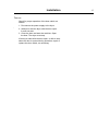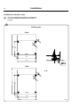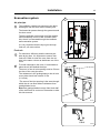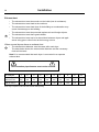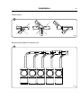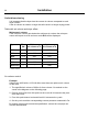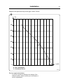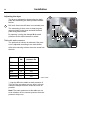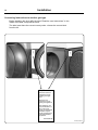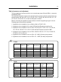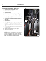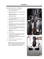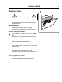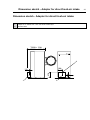
1
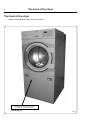
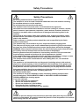
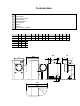
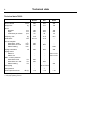
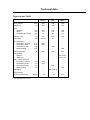
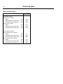
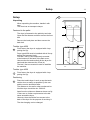
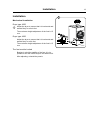
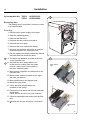
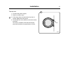
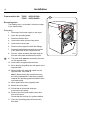
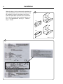
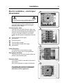
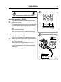
Installation manual Tumble dryers T4250, T4350 Type N2... Selecta Control Installation manual in original language 487 05 43 61/EN 2010.06.09 Contents Contents The front of the dryer.............................................................................. 4 Safety precautions.................................................................................. 5 Technical data......................................................................................... 7 Setup..................................................................................................... 11 Unpacking....................................................................................... 11 Installation............................................................................................. 13 Mechanical installation.................................................................... 13 Reversing door................................................................................ 14 Installation on board a ship............................................................. 18 Evacuation system................................................................................ 19 Air principle...................................................................................... 19 Fresh-air.......................................................................................... 19 Exhaust duct.................................................................................... 20 Outlet dimensioning......................................................................... 22 Adjusting the dryer.......................................................................... 24 Steam installation.................................................................................. 25 Gas installation...................................................................................... 29 Converting instructions to another gas type.................................... 30 Electric installation................................................................................ 35 Function check...................................................................................... 39 Dimenstion sketch – Adapter for direct fresh-air intake........................ 41 The manufacturer reserves the right to make changes to design and component specifications. 3 The front of the dryer 4 The front of the dryer Affix the enclosed sign on the front of the dryer CAUTION! Remove clothes from dryer as soon as it stops. This keeps wrinkles from setting in and reduces the possibility of spontaneous combustion 487 01 29 00.01 487 01 29 00 W00083 Safety Precautions Safety Precautions Do not dry unwashed items in the machine The machine is not to be used if industrial chemicals have been used for cleaning. Do not allow minors to use the machine. Do not hose down the machine with water. The machine's door lock must under no circumstances be bypassed. Items that have been soiled with substances such as cooking oil, acetone, alcohol, petrol, kerosene, spot removers, turpentine, waxes and wax removers should be washed in hot water with an extra amount of detergent before being dried in the machine. Items such as foam rubber (latex foam), shower caps, waterproof textiles, rubber backed articles and clothes or pillows fitted with foam rubber pads should not be dried in the machine. Fabric softeners or similar products should be used as specified by the fabric softener instructions. The machine may not be used to dry floor mops that contain polypropylene. The final part of a drying cycle occurs without heat (cool down cycle) to ensure that the items are left at a temperature that ensures that the items will not be damaged. WARNING. Never stop the machine before the end of the drying cycle unless all items are quickly removed and spread out so that the heat is dissipiated. Remove garments from the machine as soon as they are dried. This prevents them from becoming creased and reduces the risk of spontaneous ignition. If the machine develops a fault, this must be reported to the person in charge as soon as possible. This is important both for your safety and that of others. The machine must not be located where a door, sliding door, etc., can block the machine's door The machine is not intended to be used by people (including minors) with reduced physical or mental capacity or lack of experience and knowledge. Such people must be instructed in the use of the machine by a person who has responsibility for their safety. Minors must be supervised to ensure that they do not play with the machine. Adequate ventilation has to be provided to avoid the back flow of gases into the room for appliances burning other fuels, including open fires. Gas heated tumble dryer: The machine is not to be installed in rooms containing cleaning machines with perchloroethylene, TRICHLOROETHYLENE or CHLOROFLUOROCONTAINING HYDROCARBONS as cleaning agents. If you can smell gas, • Do not switch on any equipment • Do not use electrical switches • Do not use telephones in the building • Evacuate the room, building or area • Contact the person responsible for the machine In order to prevent damage to the electronics (and other parts) that may occur as the result of condensation, the machine should be placed in room temperature for 24 hours before being used for the first time. 5 Technical data ( a) (b) 1 2 3 4 5 6 7 7 Electric and gas heating Steam heating Door opening = Ø 580 Operating panel Electric connection Gas connection Steam: in Steam: out Pipe connection, evacuation A B (a) B (b) C D E F G H J K L M N O T4250 790 900 1100 1720 860 790 155 170 1505 100 1565 80 395 755 585 T4350 790 1120 1320 1720 860 790 155 170 1505 100 1565 80 395 755 585 P (a) P (b) T4250 1620 1820 740 T4350 1860 2040 740 Q (a) B (b) B (a) A (b) L J M 3 4 2 1 3 5 5 O 6 C H K 6 7 D E 7 N G F P (b) P (a) Q W00053 Technical data 8 Technical data T4250 Drum volume Weight net Drum diameter depth revolutions per minute Capacity, max Heat effect Air consumption Heat effect 9 kW Heat effect 13.5 kW Steam heating Piping evacuation Piping steam Steam in Steam out Max. counter-pressure Heat effect 9 kW Heat effect 13.5 kW Steam heating Electric Gas Steam litres 250 250 250 kg 161 161 176 mm mm rpm 760 550 45 760 550 45 760 550 45 kg 12.5 12.5 12.5 kW 9/13.5 13.5 * m3/h m3/h m3/h 360 600 - - 600 - 1000 Ø 200 200 200 - - - - ISO 7/1-R1 ISO 7/1-R1 650 520 - - 520 - 270 Pa Pa Pa Gas piping - ISO 7/1-R1/2 - Gas pressure - ** - < 70 < 70 < 70 Sound pressure level * Depending on steam pressure ** See page regarding pressure dB (A) Technical data 9 Technical data T4350 Drum volume Weight net Drum diameter depth revolutions per minute Capacity, max Heat effect Air consumption Heat effect 13.5 kW Heat effect 18 kW Heat effect 21 kW Steam heating Piping evacuation Piping steam Steam in Steam out Electric Gas Steam litres 349 349 349 kg 169 169 184 mm mm rpm 760 770 45 760 770 45 760 770 45 kg 17.5 17.5 17.5 kW 13.5/18 21 * 600 1000 - - - - 1000 - 1000 Ø 200 200 200 m3/h m3/h m3/h m3/h - - - - ISO 7/1-R1 ISO 7/1-R1 520 270 - - - - 270 - 270 Gas piping - ISO 7/1-R1/2 - Gas pressure - ** - < 70 < 70 < 70 Max. counter-pressure Heat effect 13.5 kW Heat effect 18 kW Heat effect 21 kW Steam heating Sound pressure level * Depending on steam pressure ** See page regarding pressure Pa Pa Pa Pa dB (A) 10 Technical data Motor specifications T4250, T4350 Dryer with reversal Blower motor 3-phase Effect Revolutions per minute 50 Hz Revolutions per minute 60 Hz kW rpm rpm 0.75 2700 3200 Drum motor 3-phase Effect Revolutions per minute 50 Hz Revolutions per minute 60 Hz kW rpm rpm 0.52 2700 3300 Drum / blower motor 1-phase Effect Revolutions per minute 50 Hz Revolutions per minute 60 Hz kW rpm rpm 1.0 2700 3200 Drum / blower motor 3-phase Effect Revolutions per minute 50 Hz Revolutions per minute 60 Hz kW rpm rpm 0.75 2700 3200 Dryer without reversal Setup Setup 11 1 When unpacking the machine, handle it with care. The drum has no transport clamps. 500 mm Unpacking A Fastened to the pallet The dryer is fastened to the pallet by two bolts. Open the filter drawer and then remove the front bolt. A Remove the back plate and then remove the back bolt. Tumbler type 4250 1 Tumbler type 4350 From factory the dryer is equipped with 4 supporting feet (a). Positioning 1 Min.150 mm From factory the dryer is equipped with 4 supporting feet (a). Dryer type 4250 must be installed with all 6 supporting feet mounted (a+b). The last 2 feet (b) are temporarely mounted at the bottom on the back of the back cover. Unscrew the feet and carefully tilt the dryer forward and then demount the 2 feet (b). The last 2 feet are monted in order to stabilize the machine. 1 Max. 50 mm Place the tumble dryer in such a way that work can be done as easily as possible by the user and the service technician alike. The distance to the wall or other equipment behind the dryer should be min. 500 mm. Apart from the minimum distances shown on fig. 1 there are no further requirements to the distance around the dryer. However, there should be free access to the back of the dryer for the purpose of servicing it. The door hanging can be changed. B A-A A W00054 Installation Installation 13 1 Mechanical installation Dryer type 4250 1 Adjust the dryer to ensure that it is horizontal and stands firmly on all six feet. The maximum height adjustment of the feet is 15 mm. Dryer type 4350 Adjust the dryer to ensure that it is horizontal and stands firmly on all 4 feet. The maximum height adjustment of the feet is 15 mm. The feet must be locked Bearing in mind the stability of the feet, it is important to lock the tumble dryer’s feet with nuts A. After adjusting, reinstall the panels. A A A A A A A A W00055 Installation 14 Up to machine No. T4250 –4250/101239 T4350 –4350/100824 2 Reversing door The loading door is reversible if it does not open to the desired side. Reversing 1. Disconnect the power supply to the dryer. 2. Open the operating panel. 3. Demount the filter door. 4. Unscrew the door and the front panel. 5. Unscrew the cover plate. 6. Demount the micro switch with fittings. B B 7. Squeeze out the black strip which is mounted in the back plate of the component unit 8. Run the cables including the black strip behind the back plate and across the drum. 2 9. The black strip must be mounted in the hole on the opposite side. 3 10.Unscrew the micro switch holder. Un- screw the micro switch from the holder, reverse it and mount it in the holder in the same order as before. W00056 3 Micro switch right 11.Move dummy plugs B in the side panel to the opposite side. 12.Mount holder with micro switch on the oppo- site side, use holes C. 13.Move speed nuts to the opposite side. 14.Mount the cover plate. 15.Check that all 4 terminal strips are mounted on the casing. C C 16.Reverse the front panel and the door and then mount them. Check that the felt joint is in good condition. 17.Close the operating panel and mount the filter door. 18.Unscrew the door pin and move it to position A. Micro switch left W00057, W00058 Installation Test the door 1. Connect the power supply. 2. Start the tumble dryer. 15 4 4 3. If the dryer does not start when the door is closed, adjust the door pin A. 4. Check that the micro switch on the door works correctly: The drum, ventilator and heat should stop when the front door is opened max. 40 mm. A W00059 Installation 16 From machine No. T4250 4250/101240– T4350 4350/100825– 5 Reversing door The loading door is reversible if it does not open to the desired side. Reversing B 1. Disconnect the power supply to the dryer. 2. Open the operating panel. B 3. Demount the filter door. 4. Unscrew the door and the front panel. 5. Unscrew the cover plate. 6. Demount the magnetic switch with fittings. 7. Squeeze out the black strip which is mounted in the back plate of the component unit 8. Run the cables including the black strip behind the back plate and across the drum. 5 9. The black strip must be mounted in the hole on the opposite side. 10. Unscrew the magnetic switch holder. 11. Move dummy plugs B in the side panel to the opposite side. 12. Mount holder with magnetic switch on the opposite side, use holes C. Note! When turning the bracket the wires are facing downwards. Lead them upwards towards the operating panel and fasten them with cable strips. 13. Move speed nuts to the opposite side. 14. Mount the cover plate. 15. Check that all 4 terminal strips are mounted on the casing. 16. Reverse the front panel and the door and then mount them. Check that the felt joint is in good condition. 17. Close the operating panel and mount the filter door. W00056A Installation Test run Check for proper operation of the door switch, as follows: 4 1. Re-connect the power supply to the dryer 2. Attempt to start the dryer with the door open. It must not start. 3. Close the door and start the machine. Open the door. The dryer must stop. If the dryer starts with the door open, or fails to stop when the door is opened during operation, repair or replace the door switch, as necessary. 17 Installation 18 Installation on board a ship The four accompanying fittings are fastened to the foundation by means of 4 x M10 set screws. 6 6 Drilling plan T4250 A A 557 900 FRONT 44 14 753 782 M10 T4350 A A -A A 777 1120 FRONT 44 14 753 782 M10 W00059 Installation Evacuation system 19 7 Air principle 7 The ventilator creates low pressure in the dryer, drawing air into the drum via the heating unit. The heated air passes through the garments and the drum vents. Then the air flows out through a lint filter positioned immediately in front of the ventilator. After this, the air is evacuated through the ventilator and evacuation system. It is very important that the dryer gets enough fresh air, see next section. Fresh-air 8 9 For maximum efficiency and the shortest possible drying time, it is important to ensure that fresh air is able to enter the room from the outside in the same volume as that blown out of the room. W00063 8 To avoid a draught in the room, it is advisable to place the air inlet behind the dryer. The area* of the air inlet opening must be 5 times the size of the vent pipe area. A The resistance in the grating/slats on the air inlet cover plate should not exceed 10 Pa (0.1 mbar). 5 xA *The area of the inlet opening is the area through which the air can flow without resistance from grating/slatted cover. Note that gratings/slatted covers often block half of the total fresh air vent area. Remember to take this into account. W00051 9 5xA W00048 Installation 20 Exhaust duct • The exhaust duct must be smooth on the inside (low air resistance). • The exhaust duct must lead to the outdoors. • The exhaust duct must lead clear of the building as condensation may cause frost damage to the building. • The exhaust duct must be protected against rain and foreign objects. 10 • The exhaust duct must have gentle bends. • The exhaust duct must not be a shared duct between dryers and appliances using gas or other fuels as their energy source. When several dryers share an exhaust duct 11 • The exhaust duct diameter must increase after each dryer. The table below shows the exhaust duct diameter and the necessary fresh-air inlet area. Note! It is recommended that each dryer is connected to a separate exhaust duct. The evacuation pipe diameter must not be reduced. No. of dryers 1 2 3 4 5 6 7 8 9 10 Air outlet pipe diameter in mm 200 280 315 355 400 450 475 500 535 560 Required area of fresh-air inlet m2 0.15 0.30 0.45 0.60 0.75 0.90 1.05 1.20 1.35 1.50 Each dryer requires a 400 x 400 mm fresh-air inlet opening. Installation 21 Gentle bends 10 W00049 Several dryers share an exhaust duct 11 W00052 Installation 22 Outlet dimensioning It is important that the dryer has the correct air volume compared to each dryer’s effect. If the air volume is smaller or larger this will result in a longer drying period. Table with air volume and dryer effect Minimum air volume If the outlet air volume gets below the minimum air volume the microprocessor will report an error and error code E15 will be displayed. Type Effect Minimum Optimum kW air volume m3/h air volume m3/h 4250 6/9 260 360 4250 13.5 260 600 4350 13.5 260 600 4350 18 620 1000 4350 21 620 1000 - 1000 4250/4350 ** ** Steam heated Air volume control Example: A dryer type 4350 with a 13.5 kW effect must have an optimum air volume of 600 m3/h. 1. The specified air volume of 600 m3/h from column 2 is marked on the x-axis in the diagram on the following page. 2. Draw a vertical line from this point on the x-axis till it intersects the pressure drop curve. 3. From this point draw a horizontal line till it intersects the y-axis. 4. On the y-axis read the corresponding counter-pressure measured in Pa. By means of this pressure and the specified air volume the vent pipe can now be dimensioned. Installation 23 Diagram with pressure drop curve type T4250 / T4350 12 Y = Pa 700 600 500 400 50Hz 300 200 100 0 0 200 400 600 800 X = Air consumption Y = Counter-pressure Service organisation/dealer If you have questions relating to the design of the exhaust system, please contact your local dealer or service organisation. 1000 1200 x = m3/h W00064 Installation 24 Adjusting the dryer The dryer is adjusted by dismounting the back plate and measuring the static pressure behind the fan. 13 13 Drill a ø3.3mm hole A if there is not already one. The measuring is done on a no-heat program, without clothes in the dryer and with the back plate being dismounted. 120 By opening / closing the damper B the static pressure at A is either lowered or raised. A Table with static pressure The optimum air volume is achieved if the pressure is adjusted according to the table below. After the measuring is done screw the screw into the hole. Type Effect kW Static pressure Pa 4250 6/9 760* 4250 13.5 660 4350 13.5 660 4350 18 435 4350 21 435 4250/4350 ** 435 ** Steam heated * It can be difficult to obtain a static pressure of 760 Pa if the vent pipes are very short. In these cases the damper must be closed as much as possible. Note! The static pressures in this table are not to be mistaken for the counter-pressure from the pressure drop curve. 30 B W00065 Installation Steam installation 25 14 Before start The steam pipe must be cut off and must not be under pressure. Steam a b 5 Steam 3-10 bar absolute pressure (130- 180°C). Steam forward 14 1. The branch pipe’s branch must be located at the top of the main steam pipe to prevent condensation in the steam. 2. The branch pipe must have a descending gradient and must end at a height above the inlet connecting branch (5). For measurements M, N and O, please see dimension sketch page 7. 3. Mount a plug valve (a) and a dirt collector (b) in the branch pipe. Condensation return 14 1. It is important that the branch pipe for condensed water on return to the main condensate pipe has a descending gradient and is lower than the outlet connecting branch (6). 2. Mount a dirt collector (b) in the return pipe. 3. Mount a mechanical water discharger behind the dirt collector (c). 4. Then mount a plug valve (a). 5. Mount pressure hoses between branch pipes and dryer (hoses are not supplied). O 6 a b c M N W00066 Installation 26 Steam-heated dryer 15 Mounting steam calorifier on dryer Dryer type 4250: The steam calorifier is on the pallet. Dryer type 4350: The steam calorifier is in the drum. 1. Unpack the calorifier. 15 2. Demount top back plate on the dryer. 3. Demount supporting rail on the dryer, see arrow (note which way the supporting rail turns as it has to be remounted the same way, see step 5). 4. Hang the calorifier on the bottom supporting rail on the dryer. 5. Hold the calorifier towards the dryer and remount the supporting rail as before making sure that it grasps the calorifier. 6. Screw the screws into the supporting rail. During the tightening process it is important to keep the dryer and the calorifier together. Note! After mounting the calorifier there must be no space between the dryer and the calorifier. W00067 16 7. Mount back plate. 8. Attatch the pressure hoses to the dryer’s inlet and outlet connecting branches. It is important to support the inlet and the outlet connecting brances in order to prevent deformation. 16 The pressure hoses must not hang down. W00068 Installation Leak test 1. Leak test the system. 2. Clean the dirt collectors (b), see the previous page. Function check The function check is described in the back of this manual. Pipe insulation All pipes must be insulated in order to reduce risk of burning. Insulation also reduces loss of heat to the surroundings. 27 Installation Gas installation To be carried out by qualified personnel Mount a shut-off valve upstream from the dryer. The gas connection to the dryer should be dimensioned to an output of 13.5 kW / 21 kW dependent upon the kW-rating of the dryer. The factory nozzle pressure setting corresponds to the fuel value given on the name plate. Check that the nozzle pressure and fuel value agree with the values given in the table. If not, contact the supplier. Bleed the pipe system before connecting the dryer. After connection, test all joints for leaks. 29 Installation 30 Converting instructions to another gas type Before installing the dryer affix the label "Read the user instructions" to the inside of the door, see pictures below. The label must have the correct country code - choose the correct label from the kit. 80 mm GB, IE NL Read the technical instructions before installing the appliance. Lees de technishe instructies zorgvuldig door voordat u het apparaat installeert. GB, IE NL Read the technical instructions before installing the appliance. Lees de technishe instructies zorgvuldig door voordat u het apparaat installeert. Lees de gebruikersinstructies zorgvuldig Read the user door voordat u de instructions before verlichting van het lighting the appliance. apparaat inschakelt. Dit apparaat mag This appliance may only be installed in a uitsluitend in een ruimte worden geïnroom if the room stalleerd als de meets the appropriate ruimte voldoet aan ventilation requirealle van toepassing ments specified in the zijnde eisen ten aanzien van ventilatie national installation zoals opgenomen in regulations. de nationale installatieregelgeving. 487229348.00 487229348.00. 95 mm Dit apparaat mag This appliance may only be installed in a uitsluitend in een ruimte worden geïnroom if the room stalleerd als de meets the appropriate ruimte voldoet aan ventilation requirealle van toepassing ments specified in the zijnde eisen ten aanzien van ventilatie national installation zoals opgenomen in regulations. de nationale installatieregelgeving. 487229348.00 487229348.00. 80 mm 95 mm Lees de gebruikersinstructies zorgvuldig Read the user door voordat u de instructions before verlichting van het lighting the appliance. apparaat inschakelt. 80 mm GB, IE NL Read the technical instructions before installing the appliance. Lees de technishe instructies zorgvuldig door voordat u het apparaat installeert. Lees de gebruikersinstructies zorgvuldig door voordat u de verlichting van het apparaat inschakelt. Dit apparaat mag uitsluitend in een ruimte worden geïnstalleerd als de ruimte voldoet aan alle van toepassing zijnde eisen ten aanzien van ventilatie zoals opgenomen in de nationale installatieregelgeving. 487229348.00 487229348.00. This appliance may only be installed in a room if the room meets the appropriate ventilation requirements specified in the national installation regulations. 95 mm Read the user instructions before lighting the appliance. W00069, W00070 Installation 31 Table of pressure and adjustment This gas appliance has been build to run on natural gas group I2H and I2E(LL), commonly identified by GNH. The data label shows the injector size and the injector pressure and the countries that use this gas quality: DK, NO, SE, FI, CH, CZ, EE, LT, SL, TR, BG, RO, GB, ES, GR, IE, IT, PT, AT, LV, HU, IS, SK, DE, PL, LU and non-European countries. Before connecting the appliance please make sure that the supplied gas type is correct. Following gas conversions are possible: 1. Appliances to be installed to run on GNH or GNL in FR, BE: I2E+ 2. Appliances to be installed in NL, parts of DE and Non-European countries: I2L. 3. Appliances to be installed to run on LPG in: DK, NO, SE, FI, EE, LT, SL, TR, DE, NL, CH, CZ, HU, GR, MT, CY, LV, SK, LU, BG and Non-European countries: I3B/P . 4. Appliances to be installed to run on LPG in: GB, ES, GR, IE, IT, PT, CH, CZ, BE, FR, CY, EE, LV, LT, LU, RO: I3+ . 5. Appliances to be installed to run on LPG in: AT: I3B/P (50 mbar) inlet pressure. 6. Appliances to be installed to run on LPG in: PL: I3B/P (36 mbar) inlet pressure. 1 T4250 Gas group Injector size Ø mm (1) Air reducing plate Inlet pressure (mbar) Injector pressure (mbar) Label no. (fig. 7 ) I2H, I2E(LL) 3.1 NONE 20 10 DEFAULT I2E+ 2.6 NONE 20/25 20/25 487266713 I2L (LL) 3.1 NONE 20 OR 25 15 487266713 I3B/P, I3+ 1.8 NONE 30, 28/37 30, 28/37 487266711 I3B/P (37) 1.75 NONE 37 37 487266712 I3B/P (50) 1.8 NONE 50 30 487266712 Injector size Ø mm (1) Air reducing plate (fig. 6) Inlet pressure (mbar) Injector pressure (mbar) Label no. (fig. 7) I2H, I2E(LL) 3.8 A 20 10.5 DEFAULT I2E+ 3.3 A+C 20/25 20/25 487266718 I2L (LL) 3.8 A+D 20 OR 25 15.5 487266718 I3B/P, I3+ 2.3 B 30, 28/37 30, 28/37 487266716 2 T4350 Gas group I3B/P (37) 2.1 B 37 37 487266717 I3B/P (50) 2.3 B 50 30 487266717 Installation 32 Conversion instructions - T4250 only: 1. Disconnect the power to the dryer. 2. Remove the back plate. 3. Remove nozzle. 4. Mount the enclosed nozzle (1), see Fig. 3. 3 5. Loosen the measuring branch screw (2) 1/4 turn; connect a manometer to the measuring branch (2), see Fig. 3. 6. Connect the power and select a programme with heat. 7. Start the dryer. 2 4+3 8. See nozzle pressure in table on the previous page Fig. 1 - set the nozzle pressure on setting screw (4) under cover screw (3), see Fig. 3. 9. Check that the gas flame burns evenly and has a bluish colour. 10. Mount the cover screw (3), see Fig. 3. 11.Mount the back plate. NOTE: After the conversion has been carried out, the enclosed sign with the new gas type printed on it must be affixed to the dryer data plate, see instructions on the last page. 1 W00071 Installation Conversion instructions - T4350 only: 1. Disconnect the power to the dryer. 2. Remove the back plate. 33 4 3. Remove the screw on the side of the locking plate x, see Fig. 5. 4. Pull out the locking plate x, this releases the gas pipe, see Fig. 5. 5. Remove the nozzle. 6. Turn the pipe a little and mount the supplied gas nozzle, see Fig. 2. 7. Push pipe with new nozzle back into its place. 2 4+3 8. Push locking plate all the way in and tighten the screw. 9. Replace/mount air reducing plate according to table, see Fig. 2. All air reducing plate types are shown in Fig. 6. 10. Loosen the measuring branch screw (2) 1/4 turn; connect a manometer to the measuring branch (2), see Fig. 4. 1 11.Connect the power and select a programme with heat. 12. Start the dryer. 13.See nozzle pressure in table Fig. 2 - set the nozzle pressure on setting screw (4) under cover screw (3), see Fig. 4. 14.Check that the gas flame burns evenly and has a bluish colour. W00071 5 15.Mount the cover screw (3), see Fig. 4. 16.Mount the back plate. NOTE: After the conversion has been carried out, the enclosed sign with the new gas type printed on it must be affixed to the dryer data plate, see instructions on the last page. x W00072 Installation 34 When the dryer is to be converted to another gas type, the data label on the rear of the dryer must be updated in order for the data to be correct. Place the data label enclosed in the conversion kit on top of the data label as shown below, see Fig. 7. For data label no. see Fig. 1 - T4250 or Fig. 2 - T4350. 6 A C B D W00073, 74, 75, 76 7 Installation Electric installation - electric/gas/ steamheated 35 1 L1 L2 L3 N To be carried out by qualified personnel The tumble dryer must be connected to its own fuse group and pulti-pole main switch according to IEC 60947. Connecting the cable 1 Demount the cover plate from the supply unit. The cable is led through the cable gland to the terminal block and connected as illustrated. If there is a neutral conductor in the power supply line this must be connected to terminal N: Electrical heated with supply disconnector 2 Electrical heated 3 Gas and steam heated 4 Gas and steam heated with supply disconnector W00077 2 L1 L2 L3 N W00078 3 Cable dimension For calculation of the connection cable dimension, please refer to local guidelines. Fuse group and effect The sizes of the fuse group and the effect are shown on the following page. Function check The function check is described in the back of this manual. NB: Correct direction of rotation is important! W00079 4 The tumble dryer must be equipped with supplementary protection in accordance with heavy current regulations. W00080 Installation 36 Heat effect: Type 4250 = 6 k W / 9 kW / 13.5 kW Heat effect: Type 4350 = 13.5 kW / 18 kW Heating alternative Voltage alternative Heat effect kW Motor effect kW Max. effect kW Fuse A El heating 230V 1AC 50Hz 6 1.0 6.6 30 400-480V 3AC 60Hz 9 1.0 10.3 16 400-415V 3AC 50Hz 9 1.0 10.3 16 200-240V 3AC 50/60 Hz 9 1.0 10.3 35 440-480V 3AC 60Hz 13.5 1.0 14.5 20 400-415V 3AC 50Hz 13.5 1.0 14.5 25 400-415V 3AC 60Hz 13.5 1.0 14.5 25 200-240V 3AC 50/60 Hz 13.5 1.0 14.5 50 440-480V 3AC 60Hz 18 1.0 19.3 25 400-415V 3AC 50Hz 18 1.0 19.3 35 400-415V 3AC 60Hz 18 1.0 19.3 35 230-240V 3AC 50/60Hz 18 1.0 19.3 50 200V 3AC 50/60Hz 18 1.0 19.3 63 Gas heating Steam heating 200-240V 3AC 50/60Hz – 1.0 1.1 10 400-415V 3AC 50Hz – 1.0 1.1 10 400-480V 3AC 60Hz – 1.0 1.1 10 230-240V 1AC 50Hz – 1.0 1.1 10 Installation 37 5 To be carried out by qualified personnel External connection - 100 mA 5 A special connection terminal is located on the connection console. X1 X2 Gnd. The terminal for external control is equipped with 110V/max.100mA and is intended solely for the operation of a contactor (external control of a fan). Ext. connection Max. 100mA/110V AC Max. connection 100mA. Gnd. must not be used for earthing of external board. External connection - 1.25 A 6 W00081, 84 6 If the dryer, from factory, is equipped with an external control with a max. 230V/1.25A connection this connection (1.25A) can be used as connection of an external fan. X1 X2 Gnd. Ext. connection Max. 100mA/110V AC Mount cable for external connection on contactor K7 in K7-2 and K7-4. Connect earth conductor to earth terminal in terminal for external connection. Max. connection 1.25A. N 230V K7-2 K7-4 K7-6 K7-14 K7 External connection Max. 1.25A 487 19 69 48.01 W00082 487 19 Function check Function check 24 05.01 39 1 To be carried out by qualified personnel Check whether the drum is empty and the door has been closed. Start the machine Check whether the door lock is working: The drum must stop if the front door is opened. Correct direction of rotation 1 Correct direction of rotation on fan wheel: clockwise. For dryers with a 3-phase motor the direction of rotation must be checked. If the direction of rotation is not correct, swop two phases on the connection terminal. Final test Let the dryer work for 5 minutes on a program that requires heat. Then check whether the heating is working by opening the front door and feel the heat. If the above tests-points are in order, the dryer is ready for use. Service organisation / dealer If deficiencies or errors are detected, please contact your local service organisation / dealer. W00050 Dimension sketch - Adapter for direct fresh-air intake Dimension sketch - Adapter for direct fresh-air intake Adapter kit no. 988 800 442 - Gas- and electric heated dryer Diameter Ø200 T4250 = 1130 T4350 = 1350 2 280 115 370 1 2 1 1 41 Electrolux Laundry Systems Sweden AB 341 80 Ljungby, Sweden www.electrolux.com/laundrysystems Share more of our thinking at www.electrolux.com