1
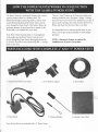
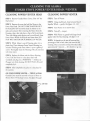
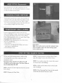
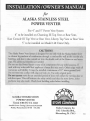
INSTALLATION/ OWNER'S MANUAL
for
ALASKA STAINLESS STEEL
POWER VENTER
[
For 4" and 5" Power Vent System
4" to be installed on Channing III Top Vent or Rear Vent,
Kast Console III Top Vent or Rear Vent, Liberty Top Vent or Rear Vent.
5" to be installed on Model 140 Units Only.
I
il
II
I
I
I
r
CAUTION!!
The Alaska Power Vent System is designed for use only with the Alaska Stoker Stove
to exhaust by-products of combustion through a combustible wall to the exterior of a
building, and also to take outside air into the double wall of the Venter to cool outer
pipe. No additional thimbles are needed.
Do not use this Power Venter or any of its components for any other purpose. If
used with any other solid fuel appliance a house fire may result. Other usage voids all
warranties and liability. It must be installed a minimum of 12" above ground level.
Do not vent into a cellar well, dug out hole, etc. Use only original parts.
Do not operate stove for an extended period of time with either the viewing door or
ash door open. This will activate the safety switch and shut the stove down, other
problems may also result. Check local building codes before installing.
ALASKASTOKER STOVE
POWER VENTER
Tested 3/88 TO UL 1482
Arnold Greene Testing Laboratories/CONAM
Natick, Massachusetts 01760 STL-002
Alaska Company, Inc.
3162 Columbia Blvd.,
Bloomsburg PA 17815
5/06
SWG SERIES POWER VENTER INSTALLATION LOCATIONS
SWGSeriesPower
VenterMust BeAt
Least1 FootAbove
DoorsOr Windows
SWGSeriesPowerVenter
Must BeMountedAt Least
3 FeetFrom InsideCorners
SWGSeries
PowerVenter
MustBeAt Least
7 FeetAbove
PublicWalkways
SWGSeriesPower
VenterMustBeAt
Least4FeetToThe
SideOfAnyDoorsOr
Windows
SWGSeries
PowerVenter
MustBeAt
Least4 Feet
BelowWindows
SWGSeriesPower
VenterMust Be
MountedAt Least
1 FootAbove
FinishedGrade
SWGSeriesPowerVenter
MustBeAt Least3 Feet
AboveAnyOutsideAir
IntakeWithin10Feet
VINYL
SIDING
SEALWITHHIGH
TEMPERATURE
~
SILICONE
SEALANT
OREQUIVALENT
VENTEROUTERPIPE
HOLELINERSAME
WIDTHASTHE
WALLTHICKNESS
INSIDE
WALL
SURFACE
EXAMPLE:
Outerpipediameter= 6"
"A" Dimension
= 7"
2
~
.
l
HOW THE POWER VENTER WORKS IN CONJUNCTION
WITH THE ALASKASTOKERSTOVE
.
There is a "reset" button on the Fume Switch Box that
The Power Venter is a mechanical chimney that creates a
negative pressure (draw) as a chimney does. The
Barometric Damper in your pipe allowsa balance to be
created between the draw of the Power Venter and the
must be pushed to reset. (Seefigure I-B page 7) Always
check this reset button first if you should lose your fire. If
button needs resetting, then check for dirty Power Vent
Wheel and check that the Stove Pipe is not dirty.
draw through the Fume Switch. This balance allowsthe
maximum amount of super heated air to remain in the
Stoker Body to be radiated into your home.
You should also have a carbonmonoxide alarm in your
home. Test the gas alarm periodically to insure proper
operation.
If the Power Venter becomes dirty or if a strong head
wind pushes into the Power Venter, room air is not
drawn through the Fume Switch allowing the heated air
in the stove to push out and trip the snap disc - cutting
power to the stove.
NOTE: A barometric damper is required for
installation on all power vent systems.
PARTS INCLUDED WITH COMPLETE 4" AND *5" POWER VENT
1. Stainless Steel Power Vent Head
2. Zero Reducer Adapter
4. Fume Switch
5. Cleaning Brushes
*Item #3 and #6 are not included with a 5" Power Venter
3
3. Trim Collar*
6. Outside Cover Plate*
INSTALLING THE ALASKA
STOKER STOVE POWER VENTER
CAUTION:
STEP 8 The Power Vent is made to fit the space
between most inside and outside walls.Test the fit by
putting the Power Vent through the wall hole. If the unit
extends too far into your room, you may want to build
and Extension Box. Once you are satisfied you can
proceed to mount as follows:
Before installing your Stove and Power
Venter, check all clearancesand local codes. (seepage2)
STEP 1 Remove all parts from Parts Box.
(see List page 3)
STEP 2 Place Stove Body on Hearth. Assemble Stove
Pipe following direction in Stove Manual.
Apply a bead of silicone around the Mounting Flange of
the PowerVent Unit.
STEP 3 Mark the location for the Power Vent exit hole
by making a light pencil mark around the outside of the
Stove Pipe.
STEP 9 Place PowerVent through wall, centered in
hole, attach with 4 screws.
STEP 4 Make the hole one inch larger then the mark
traced on wall. NOTE: When installing power vent be
sure to center the unit in the hole before attaching with
screws
STEP 10 Connect an extension cord to the Power Vent
Cord and into the wall outlet. Place the Trim Collar over
CAUTION: Locate all electricalwires, plumbing lines
and wall studs before cutting any holes.
STEP 11 Locate the Fume Switch Bolt in your Stove
Body (seepage 5). Remove bolt. Remove one of the nuts
from the Fume Switch. Put the Fume Switch Probe into
STEP 5 On the inside wall, locate the center of the hole
you have traced and drill through the outside wall. Locate
drill hole on outside of house. Mark a mark the same size
around as the mark inside of house centered with drill
hole.
the hole. Attach probe from inside the stove with the nut
you removed from the Fume Switch. On Stove Model
140 the bolt is located on the Exhaust Plate.
the Zero Reducer, slide tight to wall, place cord in notch.
Connect stove pipe Zero Reducer with 3 screws.
STEP 12 Locate the Fume Switch. Plug the female end
into Feeder Motor Assembly and the male end into a 110
Volt wall outlet.
STEP 6 Cut out holes - inside hole first. Follow the
marks.
CAUTION: Before lighting your stove be sure the Power
Venter is running. Always install a Carbon Monoxide
Detector.
STEP 7 Locate the Zero Reducer and Power Vent Head.
Insert the crimped end of Zero Reducer into extension of
the Power Venter Head. Fasten with 3 screws.
4
.
POWER VENTER APPLICATION TO
ALASKA STOKER STOVE
i/
Exterior
ofhouse
Fumeswitchlocationonstove
body.Note:locationwill vary
from modelto model.
5
CLEANING THE ALASKA
STOKER STOVE POWER VENTER HEAD / VENTER
CLEANING POWER VENTER HEAD
CLEANING POWER VENTER
STEP 1 Remove Outside Motor Cover. (Four 114" hex
STEP 1 Turn off Venter.
head screws).
STEP 2 Using small brush, clean between fins of
Impeller Wheel- gently. (Seefigures 1-2, 1-3)
STEP 2 Remove the nuts that hold the Motor to the
Power Vent Head. DO NOT FORCE MOTOR OUT
STEP 3 Turn Venter on to remove dust.
BY PULLING ON IT. Slowlyslide the Motor to the
right and outward. After removing the Motor from the
Housing, clean, dust and place a drop of oil in each port.
Then with baking soda solution and a tooth brush, clean
Power Venter Wheel of all fly ash and rinse clean. DO
NOT WET MOTOR OR SUBMERGE IN WATER!
STEP4 Turn off - inspect.
STEP5 With Venteron, gentlyhold largerbrush
againstwheelfor finalcleaning.(Seefigure1-3)
NOTE: It depends on the rate of burn and the
percentage of ash in fuel, when you must do this
cleaning. Once a month is normal. Procedure takes
approximately 5 minutes - fire should not go out.
STEP 3 While Motor is out of Housing, place it in a
plastic bag. Then submerge Power Venter Housing in a
solution of baking soda water (about 1 cup toa gallon of
water).Thoroughly clean the Housing of fly ash and rinse
with clean water.
STEP 4 Replace the Motor and the Motor Housing
Cover.Take the Venter to a dry place that's well
ventilated and plug it in. (WARNING - if Motor or
Plug got wet while cleaning, DO NOT PLUG IN until
completely dry).
STEP 5 After completely dry, place in a dry place for
the summer.
OIL YOUR POWER VENTER - TWICE A YEAR
Outside Cover must be removed to locate oil Ports on
Motor
(Four 114" hex head screws). (See figure this page)
Oil
Hole
6
ADJUSTING
Barometric
Once you have a 2" to 3" fire on the grate, set your
Barometric at .02 - .04. This allowsheated air to remain
in stoker to radiate out into home.
I
!
I
.
,..
r
I
~
TESTING FUME SWITCH
This should be tested twice a season. Place the flame of
a propane torch in the tube of the Fume Switch, inside
back of stove until Fume Switch trips. (Refer to Figure
I-A). If Fume Switch does not trip, shut down the stove,
call your dealer or replace the Fume Switch.
1-8
TEMPORARY SHUT DOWN
If your are going away for a week or two, first run
Stoker until Hopper is empty. Vacuum grate and hopper
area. Empty Ash Bucket. Clean Power Venter Wheel.
Follow lighting procedure when you restart. Burn a light
bulb inside stove to prevent moisture.
CAUTION: When shutting down your Stoker Stove,
always do the following:
1. Shut off stove.
Resetbutton
Note:Fumeswitchmustberesetaftercoolingif motor
doesnotoperate.Reset,thencheckventingsystem
beforerestartingstove.
2. Scrape hot coals off grate into Ashpan and remove
from stove to ventilated area.
3. Shut off Power Venter.
END OF THE SEASON NOTES
STEP 3 Unplug extension cord from Power Venter
plug. Place plug in center tube of PowerVenter.
At the end of the heating season, within a day
of shutting down your stove, clean your stove
and power venter.
Your power Venter should not be left in the wall
during the non-burning season. The Power Venter is
easy to remove from the wall.
STEP 4 Go outside, remove the 4 screws that connect
the Venter head to the Building.
STEP 5 Slowlypull the Power Vente):'outward until
clear of building.
STEP 1 Remove the Stove Pipe from the Stove and the
Power Venter.
STEP 6 Place Mounting Plate Cover over the outside
of the hole and reattach with the 4 screws.
STEP 2 Remove the Trim Collar.
7